


JO-TADP: Learning-Based Cooperative Dynamic Resource Allocation for MEC–UAV-Enabled Wireless Network


1
School of Electronic Engineering, Beijing University of Posts & Telecommunications, Beijing 100876, China
2
School of Communications and Information Engineering, Chongqing University of Posts and Telecommunications, Chongqing 400065, China
*
Author to whom correspondence should be addressed.
Drones 2023, 7(5), 303; https://doi.org/10.3390/drones7050303
Submission received: 6 March 2023
/
Revised: 29 April 2023
/
Accepted: 2 May 2023
/
Published: 4 May 2023
(This article belongs to the Topic Advances, Innovations and Applications of UAV Technology for Remote Sensing)
Abstract
:Providing robust communication services to mobile users (MUs) is a challenging task due to the dynamicity of MUs. Unmanned aerial vehicles (UAVs) and mobile edge computing (MEC) are used to improve connectivity by allocating resources to MUs more efficiently in a dynamic environment. However, energy consumption and lifetime issues in UAVs severely limit the resources and communication services. In this paper, we propose a dynamic cooperative resource allocation scheme for MEC–UAV-enabled wireless networks called joint optimization of trajectory, altitude, delay, and power (JO-TADP) using anarchic federated learning (AFL) and other learning algorithms to enhance data rate, use rate, and resource allocation efficiency. Initially, the MEC–UAVs are optimally positioned based on the MU density using the beluga whale optimization (BLWO) algorithm. Optimal clustering is performed in terms of splitting and merging using the triple-mode density peak clustering (TM-DPC) algorithm based on user mobility. Moreover, the trajectory, altitude, and hovering time of MEC–UAVs are predicted and optimized using the self-simulated inner attention long short-term memory (SSIA-LSTM) algorithm. Finally, the MUs and MEC–UAVs play auction games based on the classified requests, using an AFL-based cross-scale attention feature pyramid network (CSAFPN) and enhanced deep Q-learning (EDQN) algorithms for dynamic resource allocation. To validate the proposed approach, our system model has been simulated in Network Simulator 3.26 (NS-3.26). The results demonstrate that the proposed work outperforms the existing works in terms of connectivity, energy efficiency, resource allocation, and data rate.
1. Introduction
The advent increment of mobile communication devices in recent years needs resilient communication services. State-of-the-art communication networks are critically limited, with poor connectivity [1,2]. However, ground base stations (GBSs) are equipped with high computation and communication capabilities. Due to their static nature, the connectivity between mobile users (MUs) and GBSs is affected by environmental conditions during emergencies [3,4]. In general, GBSs have encountered several challenges, including poor connectivity to MUs and high sensitivity to natural disasters [5]. To address these issues of GBSs, unmanned aerial vehicles (UAVs) are adopted. The UAVs can act as a relay for MUs as well as act as a mobile base station (BS) [6,7].
UAVs as BSs are more advantageous to the MUs in terms of connectivity, coverage, and latency-free communication [8,9]. However, their network lifetime is affected by limited resource availability and battery life. In addition, the number of services, i.e., allocating resources, is also fewer due to their limited storage capacity [10]. Hence, a lot of research has been done to address this issue. To resolve the issue of limited computation and storage capacity, mobile edge computing (MEC) came into the picture [11]. MEC is being developed to enhance the computational capabilities of smart devices for executing high-computational and latency-critical tasks. However, it faces various challenges, such as improving computation, energy consumption, and latency [12]. The MECs, when combined with UAVs, allow the MUs to perform local computations on the MEC–UAVs to resolve the latency issues [13,14]. MEC–UAVs possess unique features that differentiate them from terrestrial servers. First, UAVs can adapt their location in accordance with the real-time offloading strategies of users, and their trajectory can be precisely planned for various objectives, such as enhancing throughput and conserving energy [15]. Second, MEC-assisted UAVs offer advantages compared to terrestrial servers due to their high altitude, which improves coverage by enhancing the probability of LoS with MUs and mitigates the impact of channel limitations. Leveraging these features, UAVs can make significant contributions to MEC systems and can address the deployment challenges that are associated with terrestrial servers [16]. Despite the deployment of MEC-assisted UAVs, the existing studies still lack optimal resource allocation in terms of UAV and MU constraints [17]. To achieve efficient resource allocation, the existing studies either perform joint optimization of trajectory or the position of the UAV [18]. Additionally, they consider delay, task scheduling, and offloading as sub-problems during resource allocation. However, efficient resource allocation can be achieved by considering all the constraints in a single picture [19].
Furthermore, the existing studies performed random resource allocation using deep reinforcement learning (DRL) and adopted federated learning (FL), which may affect the efficiency of resource allocation. The performance of conventional FL for resource allocation is limited by poor convergence and less learning rate. DRL and FL require significant communication overhead to transmit model parameters between nodes, which is a significant challenge in MEC–UAVs with limited bandwidth and high latency. MEC–UAVs operate in a dynamic and uncertain environment, which can make it difficult for the DRL and FL to generalize and adapt to new situations. This can result in poor performance and a high rate of failure. MEC–UAVs have limited computational and energy resources, which can limit the complexity of the models that can be deployed on them. On the other side, the existing works also consider the user constraints in terms of their density, resource requirement, and capacity to achieve user association during resource allocation [20,21]. However, none of the prior studies investigated user mobility in the environment, leading to service discontinuity [22,23]. The proposed scheme employs cooperative anarchic federated learning (AFL)-based dynamic resource allocation in edge-assisted UAV (E-UAV) by jointly optimizing UAV deployment, trajectory optimization, and altitude optimization using artificial intelligence (AI) algorithms to address the aforementioned issues in prior works.
1.1. Motivations and Objectives
Achieving energy-efficient resource allocation in the edge-enabled UAV-based wireless network remains challenging. Although state-of-the-art works have extensively considered the resource allocation approaches, the precise solution that jointly considers UAV and user constraints has not yet been provided. The state-of-the-art works are limited due to some major challenges, which are discussed below.
- Inefficient Resource Allocation: Many existing works performed resource allocation, either through optimizing the trajectory of the UAV, position of the UAV, or association between users and UAV. However, none of them jointly consider all the constraints, which leads to inefficient resource allocation. Furthermore, the resource allocation was made only using limited parameters, which also reduced the efficiency of resource allocation.
- High Energy Consumption: The existing approaches mainly rely on independent resource allocation because UAVs independently perform resource allocation rather than cooperation with other UAVs, which leads to high energy consumption. Furthermore, every MU in the environment sends direct requests to the UAVs continuously, leading to increased energy consumption.
- Service Discontinuity: Most existing methods did not consider user mobility and its characteristics. Generally, the MUs are highly dynamic; thus, it is important to consider their dynamicity, otherwise, it may lead to service discontinuity and disruption.
- Random UAV Deployment: The existing works perform 3D UAV deployment, altitude optimization, and position optimization, which are not efficient for random UAV deployment and lead to unwanted energy consumption and poor connectivity.
Motivated by the discussion above, this paper jointly optimizes UAV allocation, trajectory and altitude planning, delay, and power (JO-TADP), to achieve energy-efficient resource allocation for E-UAV-based wireless networks. Moreover, this work also addresses various resource allocation issues prevalent in existing UAV-based wireless networks. The main objective of this paper is to ensure fair resource allocation among UAVs and MUs by adopting AI algorithms and FL. To be more distinctive, the sub-objectives of this research work are provided as follows:
- To reduce poor connectivity and energy consumption by performing optimum allocation of UAVs in the environment based on the density of MUs.
- The clustering of MUs is performed, which captures the mobility of MUs to reduce unnecessary energy consumption and make the UAV more reliable.
- To reduce the hovering energy consumption and achieve better coverage by autonomous trajectory planning, deep learning (DL) is employed to optimize the UAV altitude.
- To ensure optimal and dynamic resource allocation by performing request classification, an FL-based cooperated auction mechanism using DRL is used.
1.2. Paper Contribution
This paper aims to provide adequate and optimal resources to MUs without affecting network performance. The main contributions of this paper are listed below:
- The unwanted energy consumption and poor connectivity are reduced by optimally allocating the edge-assisted UAVs in the environment based on the MU’s request using the Beluga Whale Optimization (BLWO) algorithm.
- The energy consumption is minimized, and the mobility of users is captured by clustering the MUs using the triple-mode density peak clustering (TM-DPC) algorithm. This algorithm considers several parameters, such as mobility, density, acceleration, trajectory, and speed. The algorithm also selects cluster heads (CHs) based on high stability and less mobility.
- Self-simulated inner attention long short-term memory (SSIA-LSTM) is used to optimize the hovering duration and reduce the energy consumption of MEC–UAVs during flight intervals. The autonomous trajectory planning and altitude optimization using SSIA-LSTM to enhance the coverage rate by optimally adjusting the altitude of UAVs.
- The robust resource allocation is achieved by applying an AFL-based cooperative dynamic E-UAV, which classifies the user request and performs auction-based dynamic resource allocation to MUs with less latency and optimized power consumption.
1.3. Novelty Highlights
This section emphasizes the novelty of the proposed work relative to existing methods. Table 1 summarizes the proposed solutions for the existing schemes’ shortcomings.
The proposed work is simulated and compared to the existing approaches in terms of connectivity, energy consumption, data rate, utility rate, delay time, and resource allocation efficiency. Table 2 summarizes the main notations used in this work.
1.4. Paper Organization
The rest of this paper is organized as follows. Section 2 provides a literature survey of the existing techniques. The problem formulation for the proposed work is presented in Section 3. Section 4 discusses the system model, and Section 5 further explores the system model in detail with a suitable set of equations, algorithms, and figures. The experimental results are presented in Section 6. Finally, the conclusion is drawn and presented in Section 7.
2. Literature Survey
This section surveys the existing literature on resource allocation for UAV-enabled wireless networks and their deployment. For a better understanding, the main section is further divided into two subsections, i.e., MEC–UAV-based resource allocation and UAV-based resource allocation. Table 3 summarizes several related studies with their significant research gaps.
2.1. UAV-Assisted Resource Allocation
The authors in [24] jointly optimize MU association and position by formulating a sum-rate maximization problem in UAV-enabled wireless networks. First, the UAV positions in the environments are optimized using a genetic algorithm, then the branch and bound methods are exploited to allocate resources to MUs. A load-balancing scheme has been implemented specifically for overloaded resources to improve the fairness of resource allocation. This scheme involves relaying MUs from overloaded resources to underloaded resources. A DRL-based MU association and dynamic resource allocation in UAV-enabled wireless networks are proposed in [25], where the authors deploy multiple UAVs in the environment to improve service resiliency. Multiple MUs are allowed to associate with UAVs jointly, and the UAV resources are dynamically allocated to the MUs using multi-agent DRL algorithms.
A DRL-assisted FL-based UAV network for resource allocation and scheduling is proposed in [26], where the authors exploit the global model and local model concepts for UAVs and MUs. The scheme adopts an asynchronous FL-based actor-critic algorithm to jointly optimize UAV deployment, MU association, and resource allocation. To maximize coverage area while minimizing overall system delay, the authors in [27] propose a resource allocation and trajectory optimization plan for the UAV-assisted Internet-of-Things (IoTs) networks. This study incorporates both half-duplex and full-duplex communication modes to relay and exchange information with MUs. Additionally, an iterative technique is proposed to jointly optimize the channel model, size, power, weight, and speed of the UAV.
An energy-efficient resource allocation method for UAV-based ultra-dense networks is proposed in [28], where the authors jointly optimize the power of UAVs and MUs by exploiting the Markov decision process (MDP). The scheme shows that the adoption of MDP-based deep Q-learning reduces the computation complexity, therefore increasing the fairness in resource allocation. A joint resource allocation and trajectory optimization for UAV-enabled wireless networks is proposed in [29], where the authors jointly optimize UAV trajectory, power of UAVs and MUs, resource scheduling, and time to minimize the overall system energy consumption. A ruin theory-based energy-saving technique for cellular resource allocation is presented in [30], where the authors exploit the water-filling algorithm to optimize power jointly and MU association by enabling a trade-off between reliability and delay.
In [31], the authors formulate an energy consumption minimization problem in non-orthogonal multiple access (NOMA)-empowered wireless networks. This work loops three processes for optimal resource allocation, i.e., first, the MUs are selected based on the heuristic algorithm, then the power allocation is performed, and finally, the data rate, channel model, and energy level are taken into account to optimize the trajectory of UAV. The authors in [32] jointly formulate resource allocation and UAV placement as an energy consumption minimization problem and exploit the K-means clustering algorithm to group multiple MUs into one cluster and optimally allocate power to them. A sum-rate maximization problem for collaborative UAV-based wireless networks is proposed in [33]. The authors jointly optimize UAV position, MU association, power allocation, and channel allocation using deep Q-learning (DQN).
A QoS-aware deep deterministic policy gradient (DDPG)-based algorithm for latency minimization in a UAV-assisted wireless network is proposed in [34], where the authors jointly optimize resource allocation and task offloading. The authors in [35] propose a virtual cognitive resource allocation algorithm in a 5G-assisted UAV network. To assign virtual resources to MUs, resources are initially allocated based on the MU’s on-demand requests. Subsequently, resources are reallocated to the MUs to ensure QoS.
To minimize the overall system energy consumption for a UAV-enabled emergency network, the authors in [36] jointly optimize UAV location and resource allocation. In [37], the authors jointly optimize power allocation and UAV trajectory design and employ a DRL-based algorithm to minimize the overall system delay. In this work, each UAV acts as an agent to perform resource allocation and trajectory planning in an optimized manner based on path loss, transmission channel, and on-demand requests.
2.2. MEC–UAV-Assisted Resource Allocation
An energy consumption minimization-based joint trajectory planning and resource allocation strategy is proposed in [38], where the authors introduce a partial task offloading framework and propose an iterative algorithm to obtain the optimal strategies. A cooperative resource allocation and communication framework is presented between the MUs and UAVs in 3D space [39]. The authors jointly optimize UAV deployment and resource allocation and formulate the original problem as a mixed integer non-linear programming problem. An iterative algorithm is proposed that optimizes deployment, resource allocation, and the association problem jointly based on the UAV height, channel bandwidth, and elevation angle.
In [40], the authors jointly optimize computation offloading and computation time in a dual-stage edge-enabled UAV network. A block successive upper bound minimization algorithm is proposed for the channel allocation, and the authors further consider that if the UAV becomes unresponsive due to low battery power, a portion of the task is offloaded to the terrestrial base station. A cooperative resource allocation strategy for a UAV-assisted MEC network is proposed in [41], where the authors jointly optimize user tasks, computation time, trajectory planning, and power allocation and use Lagrange-based methods to obtain the optimal strategies.
A joint computation offloading and resource allocation scheme for edge-enabled UAV networks is proposed based on the characteristics of the task, i.e., size and CPU cycles required [42]. The authors propose a semi-qualitative relaxation method to optimize bandwidth and power rate. Eventually, a position optimization algorithm is used to optimize the placement of the UAV. An energy-efficient resource allocation strategy in an edge-assisted UAV network for disaster-vulnerable areas is proposed in [43], where the authors consider both the uplink and downlink communication scenarios to enable resilient connectivity by optimizing the trajectories of UAVs. An iterative algorithm following the Lagrange dual method-based scheme is used to ensure optimal resource allocation.
3. Problem Formulation
In this section, we jointly formulate the problem of UAV allocation, trajectory planning, altitude planning, delay minimization, power minimization, and offloading as a maximization-minimization problem. To enhance resource allocation efficiency between MUs and UAVs, the minimization problem can be formulated as follows:
In Equation (1a) represents the energy consumption of MUs and UAVs, is the total available energy for all MUs and UAVs. Equation (1a) represents the energy consumption constraints of MUs and UAVs, which states that the energy consumed by the users and UAVs must be less than or equal to the total available energy. In Equation (1b), is delay encountered by MUs and UAVs, and is the maximum possible delay. In Equation (1c), represents the computational delay. Equation (1b,c) shows the delay constraints to perform an action, which ensures that the delay encountered by the users and UAVs must be less than the maximum possible delay for successful transmission. The computational delay encountered by UAVs and MUs must be greater than 0 and less than or equal to one. In Equation (1d), denotes the power consumption of users and UAVs, while represents the overall power available for task completion. In Equation (1e), denotes computational power. Equation (1d,e) represent the power consumption constraints of MU and UAVs for completing a task, which state that the power for the MUs and UAVs must be less than or equal to the maximum available power allocated for all tasks. The computational power consumed by UAVs and MUs must be greater than 0 and less than or equal to one, as stated in Equation (1e). In Equation (1f), represents the computational time, while is the total available computational time. In Equation (1g), represents the offloaded computational time. Similarly, Equation (1f,g) show that the offloading computation is performed within the total offloading computation time.
Having stated that,
Equation (2) represents the overall sum-rate maximization problem, denotes the optimization constant to maximize the UAV constraints in the environment. In Equations (2a) and (2b), represents the sub-channel allocation. The constraints in Equations (2a) and (2b) indicate that only one sub-channel can be allocated to the underlying MUs during resource allocation. Please note that the sub-channel assignment is only for the associated MUs. Equation (2c) indicates altitude optimization constraint, where the UAV altitude can be adjusted based on the user density level within the lower and higher connectivity ranges of MUs. In Equation (2d), and denote the starting and ending trajectory of UAVs. Equations (2d) and (2e) denote trajectory optimization constraints, which determine the starting and ending points for UAV hovering to reduce the collision rate.
4. System Model
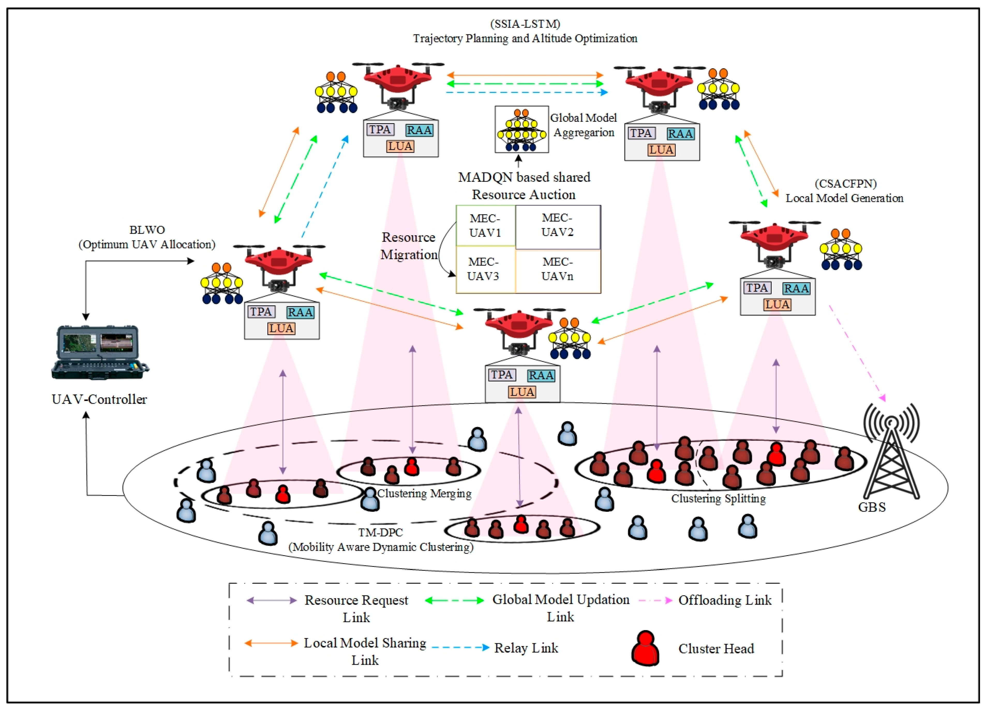
This section explains the proposed JO-TADP for resource allocation in MEC–UAVs. The major theme of the proposed work is to enable an energy-efficient resource management framework for MEC–UAVs using machine-learning algorithms. The proposed work adopts an AFL for efficient resource allocation in a UAV-enabled network, improving the convergence rate by allowing the MUs to intendedly participate in federated learning. By implementing an AFL, MUs can decide when to participate in FL and how many steps to perform during each round based on their battery life and communication channel. In addition, it reduces the delay and helps to achieve distributed resource allocation, which improves the MU data rate. The system model is composed of entities such as MUs, edge-assisted UAVs (MEC–UAVs), 5G GBSs, and UAV controllers (UAV-Con). The E-UAVs consist of three agents, namely trajectory planning agent (TPA), look-up agent (LUA), and resource allocator agent (RAA). The proposed JO-TADP-based resource allocation architecture is shown in Figure 1.
4.1. Network Model
In the proposed network, we consider a set of MEC–UAVs denoted as , one GBS, and a set of MUs denoted as . Although the GBS provides connectivity and services to the MUs, in real-time scenarios, the GBS can easily flop and be affected by environmental changes. In that case, the UAVs are deployed as BSs to serve the MUs; however, the conventional UAVs are resource-constraint devices, i.e., they have limited computation and storage capabilities. The JO-TADP method provides an alternate solution by deploying edge-assisted UAVs in an environment closer to the network. More specifically, the deployment of MEC–UAVs improves MU association, as MUs possess high mobility in the environment and can only perform less computationally intensive tasks, while the other tasks are offloaded to the MEC–UAVs or the GBS.
MEC–UAVs are deployed in the environment to allocate resources dynamically between MUs, which enhances the sum rate and spectrum efficiency. The multiple MEC–UAVs collaborate to provide a set of Z channels denoted as for each time slot t. In the proposed environment, the channel assignment is given in two different bandwidth terms, i.e., familiar and non-familiar. The bandwidth of familiar and non-familiar channels can be denoted as and , respectively. , where represents the bandwidth allocation for the familiar channel for the th UAV at time slot t. Similarly, for the non-familiar channel, the bandwidth allocation is denoted as . Following is a list of assumptions considered in the proposed work:
- A1: It is assumed that the MUs maintain a local database for executing fewer local computations.
- A2: It is considered that the MEC–UAVs have a higher capability and capacity to handle AI algorithms and execute computationally intensive tasks locally. Only in rare cases are the tasks from the UAVs offloaded to the GBSs.
- A3: The MEC–UAVs know the locations of other MEC–UAVs and MUs in the environment.
- A4: It is assumed that the MEC–UAVs generate local and shared global models for resource allocation using an AFL.
- A5: It is assumed that the multiple MEC–UAVs in the proposed environment do not collide with each other.
4.2. Modeling of Delay
The delay model is based on computation and transmission delay. The resource request of each MU is characterized as where denote the size of the request, the number of CPU cycles required to compute the request, and the type of resource, i.e., familiar or non-familiar. As we assumed, the MEC–UAV resource is adequate for entertaining the MU’s request. We formulate the total delay here as the sum of transmission and computation delays. The transmission delay among the MUs and UAVs can be computed as:
where denotes the transmission delay, and represents the channel bandwidth. Similarly, the computational delay can be formulated as:
where denotes the computational delay, and is the resource availability of the proposed MEC–UAVs. Please note that in this work, MEC–UAVs provide only one channel to MUs as a token for the association, which can be represented as:
where is the MU association variable, i.e., if , then the resources are allocated by nearby GBS; otherwise, if , then the resources are allocated by MEC–UAVs. Therefore, the delay in computing the offloaded resources can be formulated as:
where denotes the task splitting ratio, i.e., if , then the tasks of MUs are completely executed at MEC–UAVs; otherwise, if , then the tasks of MUs are executed at GBS and can be formulated as:
Therefore, the overall delay of the proposed system can be modeled as:
4.3. Modeling of MU Association and Resource Allocation
As the MEC–UAVs are in various locations, the channel gain may vary. Therefore, the MEC–UAVs must optimize their power, MU association, and channel assignment strategies. The proposed work adopts a () matrix representation for amplifying the state of the UAV at a given time slot . The matrix can be represented as , where .
We assume that every MU can only occupy one channel; therefore, for the sake of simplicity, we consider the following constraints:
We assume that the channel resources are dynamically allocated to the MUs, which leads to co-channel interference; therefore, the transmission power needs to be optimized, which can be formulated as:
where denotes the transmission power, S represents the number of channels in the MEC–UAV, and is the maximum budget for transmission power allocated by MEC–UAVs.
4.4. Modeling of Energy Consumption
The energy consumption of MEC–UAVs can be modeled in terms of computation offloading and hovering, respectively. Therefore, the energy consumption of MEC–UAVs for computing the resource allocation requests can be formulated as:
where denotes the CPU frequency required to compute the MU request, and represents the resource availability of MEC–UAVs. represents the offloaded data size of MUs to MEC–UAVs, and denotes the amount of task portion offloaded to MEC–UAVs. The MEC–UAVs encounter high computation overhead due to high mobility and MU density. Therefore, in this case, the MU request can be offloaded to GBS. The latency while offloading the MU request from MEC–UAVs to GBS can be expressed as:
where denotes the communication bandwidth for the MEC–UAVs to communicate with the GBS, and denotes the signal-to-noise ratio of the channel among MEC–UAVs and GBS. Therefore, the energy consumption of MEC–UAVs during task offloading to GBS can be formulated as:
Based on the above equations, the total energy consumption for task computation in MEC–UAVs and GBS can be formulated as:
We assume that the MEC–UAVs are not fixed during resource allocation and need to hover around the location to provide the resources. Therefore, the hovering energy consumption of MEC–UAVs can be formulated as:
where denotes the energy consumption, represents the power consumption, and denotes the time consumption of MEC–UAVs during hovering. can be represented as:
where denotes the power efficiency of MEC–UAV, denote the density of air and rotor diameter. represents the rotor requirement of the MEC–UAV, and denotes the thrust of the MEC–UAV based on mass. Therefore, the total energy consumption of the MEC–UAVs for hovering, relaying, i.e., offloading to GBS, and offloading can be written as:
5. Proposed JO-TADP Model
In this section, the mathematical modeling of the proposed work is explained based on the system model with suitable equations, pseudocode, and diagrammatic illustrations. Specifically, the proposed JO-TADP model is composed of four significant steps:
- Optimum UAV allocation
- Mobility-aware dynamic MU clustering
- DL-based autonomous trajectory planning and altitude optimization
- AFL-based cooperative dynamic UAV resource allocation
5.1. Optimum UAV Allocation
Initially, the MUs are providing a request to the UAV controller regarding their density level in the environment. The UAV controller is responsible for allocating the E-UAVs based on the MU request for a reasonable cost. After receiving the request, the UAV controller uses the BLWO method to optimally allocate the number of UAVs to the regions based on the density of the MUs. The optimal placement of UAVs in the network reduces both poor connectivity and unwanted energy consumption. By mimicking the behaviors such as attacking, swimming, and falling of beluga whales, the BLWO algorithm is adopted. In this work, the MEC–UAVs are considered the beluga whales, and MUs are the prey. The BLWO algorithm consists of three main phases: exploitation, exploration, and fall of the beluga whale. First, the population of the MEC–UAVs is initialized based on the size of the population and dimension, which can be represented as:
where denotes the dimension of variables, and represents the size of the population of the MEC–UAVs. The fitness values of the MEC–UAVs can be formulated as:
The harmonizing factor between exploration and exploitation can be formulated as:
where denotes the deciding sub-factor for every iteration which is changed among (0, 1), denotes the present iteration, and denotes the maximum iteration. The changes between exploration and exploitation can be given as:
5.1.1. Global Search Phase
The exploration or global search phase is based on a synchronized manner, i.e., two MEC–UAVs can optimize their positions according to MU density. Therefore, the position update of MEC–UAVs for every search can be formulated as:
where denotes the updated position of the j-th MEC–UAV on the dimension, and denote the current positions of the r-th and j-th MEC–UAV. are the random numbers for enhancing the global search phase, represent the synchronization functions directed to the MEC–UAVs for optimal allocation.
5.1.2. Local Search Phase
The UAV controller allocates MEC–UAVs cooperatively during the local search phase, i.e., the exploitation phase, to ensure that the position of each MEC–UAV is known by the others. The levy flight method is used to improve the convergence rate in the local search phase, which can be expressed as:
where denotes the updated position of the MEC–UAVs based on the MU density, denotes the best position of the MEC–UAVs, and denotes the intensity of the levy flight.
5.1.3. Optimum Allocation Phase
In the proposed scenario, we assume that the UAV controller optimally initializes the positions of MEC–UAVs. The UAVs may fail to deliver reliable communication if the number of UAVs randomly assigned is lower than the density level. In addition, deploying UAVs for a limited number of MUs may result in unwanted energy consumption. Please note that the optimum deployment of UAVs in the network reduces unwanted energy consumption and enhances connectivity among the MUs. To model the optimum allocation of MEC–UAVs, we jointly consider the size of the population, the position of the MEC–UAV, and the step size, which can be written as:
where denotes the step size of the MEC–UAVs, which can be expressed as:
where and denote the upper and lower boundary variables, and denotes the probability of the step factor. Therefore, the probability of MEC–UAVs falling can be formulated as:
It can be noticed that the probability is decreased from 0.1 to 0.05, which shows that the MEC–UAVs are deployed in an optimum number based on the MU density. The working of optimum MEC–UAV allocation is proposed in Algorithm 1.
5.2. Mobility-Aware Dynamic Clustering
The MUs are clustered once the UAVs have been optimally allocated. The clustering is made by LUA to reduce energy consumption and capture the mobility of MUs in the environment. In this work, the MU clustering is based on their speed , trajectory , position , and acceleration , which are collectively represented as using the TM-DPC algorithm. The reason for adopting this algorithm is that it reduces the cluster propagation error in the state-of-the-art DPC algorithm and ensures highly suitable clusters. For MU clustering, the cluster centers are initially determined based on the state-of-the-art density peak clustering algorithm, according to which a cluster center of MUs must satisfy the following constraints:
- Cluster centers of MUs have increased local density
- Increased distance from the other cluster center
Based on the above constraints, local density and distance based on must be computed for all the MUs, and is given as:
| Algorithm 1 Optimum MEC–UAV Allocation |
| Input: , |
| Output: Optimum MEC–UAV Allocation |
| Start |
| Population initialization and fitness evaluation using Equations (20) and (21) |
| While |
| Determine harmonization factor using Equation (22) |
| For every do |
| If then |
| ‘Global Search Phase’ |
| Update the position of MEC–UAVs using Equation (23) |
| Else If |
| ‘Local Search Phase’ |
| Computing levy flight and apprise the intensity factor |
| Update the position of MEC–UAVs using Equation (24) |
| End If |
| End For |
| For every do |
| ‘Optimum MEC–UAVs Allocation Phase’ |
| If then |
| Intensity factor updating |
| Compute the using Equation (26) |
| Update the position |
| Determine the using Equation (27) |
| End If |
| End For |
| iter = iter + 1 |
| End While |
| Return Optimum MEC–UAV Allocation |
| End |
From the above Equations (28)–(30), denotes the Euclidean distance between the ni-th MU to the nj-th MU, and represents the cut-off distance. The cluster center can be computed using pairs, which can be formulated as:
From the set of MUs, a MU with increased , and can be selected as the cluster center. The set of MU clusters can be represented as . To calculate the noise point or noisy MU, first the maximum Euclidian distance between ni and its nearest neighbor is calculated. Then the mean of can be calculated as:
If the is greater than the mean to maximum distance (), i.e., > ℶ, then the ni-th MU is noisy. The set of noisy MUs can be represented as .
Once the noisy MUs and center of the MU cluster are computed, the proposed TM-DPC cancels the noisy MUs from the cluster list and aims to determine the core MUs in the environment. For every cluster center, i.e., , is determined by computing the mid-range based on , which can be formulated as:
Based on , if , then the point is added to the positive cluster regions. The positive cluster regions are the core points which are represented as . Aside from the positive cluster regions of each location, the MUs at the border of each cluster are considered negative regions. The MUs in negative regions are processed based on evidence theory. The evidence theory determines the appropriate cluster for those MUs in the negative region. Based on the evidence theory, the co-efficient of support and mass function can be determined. The co-efficient of support can be expressed as:
where represents the similarity among the ni and . The mass function can be written as:
In Equation (35), if , the negative MU is a cluster member of , else, . The first expression, i.e., denotes the negative MU nj is in the cluster with sureness level . denotes that there is no relation between the nj and ni with a sureness level of . In this case, the mass function is computed for each negative MU (nj = {j = 1,2…, k}). The final cluster formed can be represented as . After clustering, the CH is selected based on high stability and low mobility. The selected CH is responsible for forwarding data to the UAVs by collecting information about their members. Since MUs are highly dynamic, we perform intelligent cluster management by merging and splitting clusters based on the MU density level and speed. The cluster management is based on the pre-defined cluster density level threshold . Based on , the cluster management process is given by:
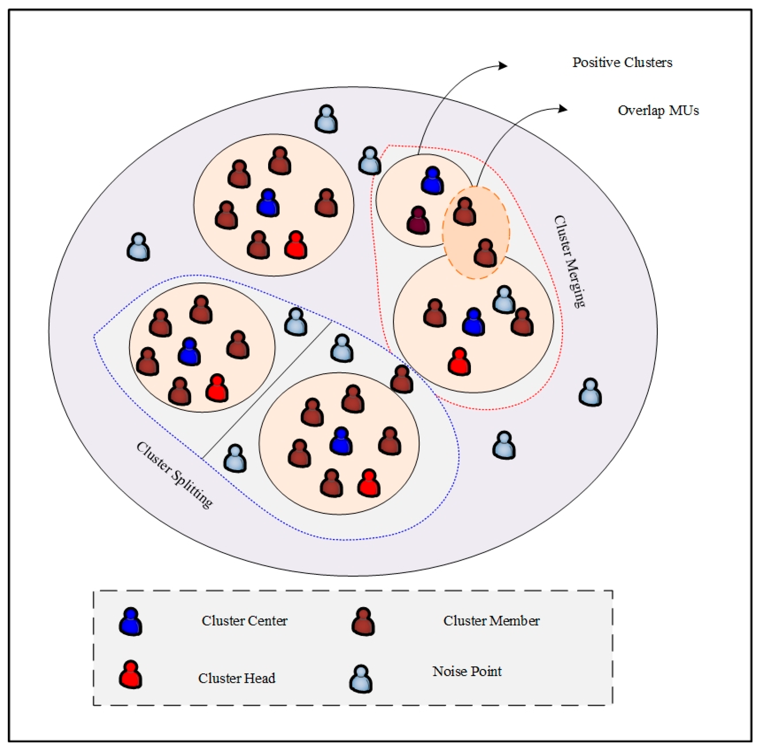
Please note that the cluster management can be defined as follows: if the pre-defined density threshold is less than the cluster density, the corresponding cluster is split up. If the pre-defined threshold value is higher than the cluster density, the cluster is merged with the other cluster. For both cases, the CH selection process is again initiated. Figure 2 represents the TM-DPC-based mobility-aware dynamic clustering.
5.3. DL-Based Autonomous Trajectory Planning and Altitude Optimization
Eventually, the MEC–UAVs jointly optimize the trajectory and altitude autonomously to reduce the energy consumption due to unwanted hovering and provide better coverage to the MUs for efficient resource allocation. The proposed work uses SSIA-LSTM to perform joint trajectory planning and altitude optimization using metrics such as the history of weather records , speed of the MEC–UAV , the energy of the MEC–UAV , kinematics properties , and mobility model of the MEC–UAV. The above metrics are collectively mentioned as . The standard kinematics equation in [44] has been extended to 3D for the position, acceleration, and jerk of the UAV. The kinematic properties of the MEC–UAVs can be determined by the following equation:
The kinematic properties of the MEC–UAVs are designed in a 3D plane. denote the acceleration, position, and velocity of the MEC–UAVs in a 3D plane. denote the jerks of the MEC–UAVs in a 3D plane. To estimate the position of a UAV, it is necessary to add the acceleration and jerk values over time. Therefore, acceleration and jerk measurements in 3D coordinates can provide valuable information for tracking the motion of a UAV. To provide the position of the UAV in x, y, and z coordinates, the jerks in the x coordinate of the MEC–UAV can be formulated as:
Similar equations can be formulated for the other two coordinates, i.e., y and z. The proposed mobility model of MEC–UAVs in 3D reduces data loss during simulation. The metrics are provided as input to the SSIA-LSTM for trajectory planning and altitude optimization as shown in Figure 3. The reason for adopting SSIA-LSTM is that it improves the prediction rate by reducing unwanted biases.
Using the predicted data from the SSIA-LSTM, the TPA controls the MEC–UAV more efficiently in terms of optimal trajectory planning with high gain, altitude adjustment of the UAV, and hover time of the UAV. The general LSTM network is composed of forget, input, and output gates, respectively. Two activation functions, namely hyperbolic and sigmoidal activation functions are adopted. The SSIA is placed above the hyperbolic tangent (tanh) function to improve the information flow and prediction rate. For a given input, i.e., , the metric for weight function and error can be written as:
where denotes the weight matrix of the gate, denotes the vector error, and denotes the sigmoid function. The given input , and previous hidden state is provided to the forget gate , which can be formulated as:
where is used to filter out the unwanted information from the provided input, denotes the weight of forget gate, and denotes the error during forget gate. Next, the input gate, i.e., is shown, which takes and as an input and can be formulated as:
Similarly, for the current time can be computed based on and , and can be formulated as:
After that, is passed through the SSIA in the form of a matrix, which can be represented as:
The equations listed in the SSIA mechanism can be formulated as follows:
From Equations (44)–(47), and indicate the matrix dimension of the first and second hidden unit, and represents the length of the time step of the query matrix and key matrix . denotes the attention score matrix, denotes the output of the attention layer and is the element-wise Hadamard multiplication operator. The current state is given below.
| Algorithm 2 DL-based Trajectory Planning and Altitude Optimization |
| Input: Trajectory and Altitude Optimization Metrics |
| Output: |
| Start |
| Initialize |
| For all the MEC–UAVs do |
| Compute according to Equations (37) and (38) |
| For do |
| Initialize the gates according to Equation (39) |
| Determine the forget gate according to Equation (40) |
| Determine the Input gate according to Equation (41) |
| Determine according to Equation (42) |
| \* Self-Stimulated Inner Attention (SSIA)\* |
| Represent in the form of a matrix according to Equation (43) |
| Compute QM and KM according to Equations (44) and (45) |
| Compute ASM according to Equation (46) |
| Compute according to Equation (47) |
| Determine according to Equation (48) |
| Determine and according to Equations (49) and (50) |
| End For |
| Perform |
| Perform |
| Perform |
| End For |
| End |
The output gate, i.e., controls the current output from the rest of the two gates with SSIA, and can be formulated as:
5.4. AFL-Based Cooperative Dynamic MEC–UAV Resource Allocation
Finally, the RAA allocates cooperative resources by optimizing the MU delay and power consumption. The task classification method and optimal migration are used to reduce delay during resource allocation. The power consumption of MU and MEC–UAV is reduced by adopting shared AFL. The proposed approach splits the resources into two bandwidth levels: familiar resource bandwidth, i.e., online streaming videos, virtual reality (VR), etc., and non-familiar resource bandwidth, i.e., an emergency which is rarely happened and can be formulated as:
Dividing resources into familiar and non-familiar groups can help optimize communication costs and accelerate the convergence of the shared model in AFL. The CHs in all clusters continuously send requests to the MEC–UAVs, which consist of metrics such as MU battery level, channel quality information (CQI), required bandwidth, energy efficiency, spectral efficiency, delay, and resource type, which are collectively mentioned as . from the MUs are handled by the LUA, which uses MTNP-SVM to perform request classification. The reason for adopting MTNP-SVM is that it improves classification efficiency by reducing the problem of matrix inversion operation. The MTNP-SVM is composed of two decision hyperplanes, i.e., positive and negative, denoted as , where and , respectively. For the given , the decision hyperplanes are represented as and . The output of the given request can be determined based on the two following decision hyperplanes:
Based on the above two decision hyperplanes, the output can be written as:
The classified results are forwarded to RAA for cooperated resource allocation. Based on the classified results, the RAA agents initially allocate bandwidth to unfamiliar resources due to their lower convergence rate. For familiar resources, there would be a high rate of convergence. Therefore, the proposed work uses an AFL, which allocates resources cooperatively. In conventional FL, the authorization is completed on the server side. The server must decide which MU will perform, how many steps etc., which affects the fairness because only the high-potential MUs benefit from this, while the less potential MUs with limited computation and communication capabilities must wait until all the high-potential MUs complete the FL process. The conventional FL issues are addressed by proposing an AFL, in which MUs are independent in making their own decision regarding their local model generation, which improves fairness in the environment [45]. Table 4 denotes the properties of servers and clients in the proposed AFL method.
5.4.1. Local Model Generation
The local model is generated by the E-UAVs using a DL algorithm known as cross-scale attention combination feature pyramidal network (CSACFPN). This algorithm is based on the independent requests of the MUs participating in the FL, including their energy level, the type of resources required, and the number of steps in which they participate in the FL. The adoption of CSACPN improves the accuracy of model generation and refines the output results using the attention and adaptive fusion method. The CSACFPN consists of a convolutional block attention module with two sub-attention modules, namely channel and spatial attention modules. First, the local input model of MUs, i.e., Rreq, is provided to the convolutional layers . Rreq is processed by the convolutional layer and provided to the feature layer for feature generation, which can be formulated as:
where represents the output features from the feature generation layer, denotes the operation of concatenation for extracting the important information during feature generation, denotes the up-sampling operation, and is the convolutional layer operations. By performing the process of up-sampling, the important features might be lost, which would affect the local model generation accuracy. For that, the extracted output feature is provided to the convolutional block attention module, which generates the feature map with enhanced information by suppressing the unwanted information, which can be written as:
where denotes the convolutional block attention module. The enhanced features are further provided to the channel attention module for extracting significant global information. The channel attention module is composed of two layers of multi-layer perceptron module for generating the feature map as:
where denotes the activation function, and are the weights of two multi-layer perceptrons, respectively. Similarly, for the spatial attention module, the generated feature map can be represented as:
After performing all the attention, the final feature map can be written as:
where BAN and ReLU denote the batch normalization and activation function. The optimal local model is generated from the feature map using the adaptive fusion method and element-wise addition, which can be expressed as:
The fused information is provided to the SoftMax layer for the final output, which can be formulated as:
From the above equation, the local model is obtained with rich information, fewer errors, and higher accuracy. The generated local model of the MUs is provided to the MEC–UAVs for developing shared global model generation, i.e., dynamic resource allocation.
5.4.2. Shared Global Model Generation
After generating the local model, each MEC–UAV shared its local model with all the other MEC–UAVs within its coverage area to generate the global model collaboratively. All the MEC–UAVs perform cooperative on-demand shared dynamic resource allocation by auction mechanism using an enhanced deep Q-learning algorithm (EDQN). Conventional Q-learning is enhanced by performing function regularization to ensure speed and stability in target networks. In this work, all the MEC–UAVs are in a dual role as buyer and seller. Since each MEC–UAV is configured differently, resources are sold and bought from other participating MEC–UAVs based on MU requests. The shared results are considered a global model and provided to MUs.
First, we model the dynamic resource allocation model for MEC–UAVs. Every MEC–UAV has resource channels, i.e., , and CPU cycles. Based on the MU request, the MEC–UAVs cooperate with the other MEC–UAVs. In the proposed method, every MEC–UAV adjusts its global shared model generation strategy based on the MU request to achieve ample resource allocation to MUs. Therefore, every MEC–UAV in the environment tries to maximize the utility function, which can be formulated as:
where represents the utility function of j-th MEC–UAV with the constraint of providing the requested resources to the MUs, and denotes the other cooperated MEC–UAV utility function excluding the j-th MEC–UAV. Based on the utility function, each MEC–UAV generates a shared global model using the EDQN algorithm, which uses the MDP to interact with the environment. The environment is composed of tuples, such as , which are stated below:
- : It denotes the current state of MEC–UAVs, i.e., availability of resources, amount of CPU cycles, and current cost.
- : It denotes the actions taken by the MEC–UAVs in the environment, i.e., shared dynamic resource allocation based on the MU constraints.
- : Maximizing the utility function and satisfying the QoS of MUs.
Other than that, denotes the dynamic state metric for invoking future actions, which can be represented as , indicate the discount and initial state distribution factor. The agent in the proposed EDQN tried to maximize the expected reward function as with the policy of . Therefore, the best state value pairs can be obtained by the Bellman equation, which can be formulated as:
where denotes the optimal policy, and denotes the target network. To stabilize the learning rate, we adopt the function regularization approach, which can compensate for the stability and speed of the proposed global model generation. The regularization of penalizes can be formulated as:
where denotes the error of the Bellman equation for function regularization, denotes the operator stop gradient, and denote the present and lagged estimate of value, and is the L-2 regularization function. Based on the above equations, the shared global model can be presented as:
When MUs are within the coverage of MEC–UAVs, they act as a relay, and other MEC–UAVs allocate resources to the MUs.
| Algorithm 3 AFL-Based Shared Dynamic Resource Allocation |
| Input: Non-Familiar Resource Request from MUs |
| Output: Shared Dynamic Resource Allocation |
| Start |
| While all the non-familiar requests do |
| For all the MUs do |
| Perform local model generation according to Equations (55)–(61) |
| Provide the local model to MEC–UAVs |
| End For |
| For do |
| For all the MEC–UAVs do |
| Perform shared dynamic global model generation using Equations (62)–(64) |
| AFL-based shared global model, according to Equation (65) |
| End For |
| End For |
| End While |
| End |
Additionally, resource migration is performed to ensure fair resource allocation based on mobility pattern of MUs and the availability of resources. The adoption of auction-based DRL for local model generation reduces the risk of random resource allocation by optimally allocating the resources to the MUs. Figure 4 denotes the dynamic resource allocation model using the EDQN algorithm.
6. Experimental Results
This section provides the experimental results of the proposed dynamic cooperative resource allocation scheme using an AFL and AI algorithm. For a better understanding, we divide the main section into three subsections: simulation setup, comparative analysis, and research summary.
6.1. Simulation Setup
The proposed JO-TADP-based cooperative MEC–UAV resource allocation using an AFL is tested and simulated using Network Simulator 3.26 (NS-3.26). To realize the resilient simulation output, we have configured our system in terms of hardware and software settings. The hardware setting includes a processor of Intel (R) Core (TM) i5-4590S CPU@ 3.00 GHz, a hard disk of 1 Tera Bytes (TBs), and random-access memory (RAM) of 6GB. The operating system required for simulating the proposed work is Ubuntu 14.04 LTS, and the simulation tool package installed is NS-3.26. In addition to the system requirements, the network parameters are also taken for simulation. Table 5 provides the simulation configurations along with the algorithm parameters.
6.2. Comparative Analysis
This subsection provides the comparative analysis of the proposed JO-TADP scheme with the existing approaches such as JO-PUARA [24], EdgeUAV [38], and Multi-UAV [25] in terms of simulation metrics such as connectivity, energy efficiency, utility rate, data rate, delay time and resource allocation efficiency.
6.2.1. Analysis of Connectivity
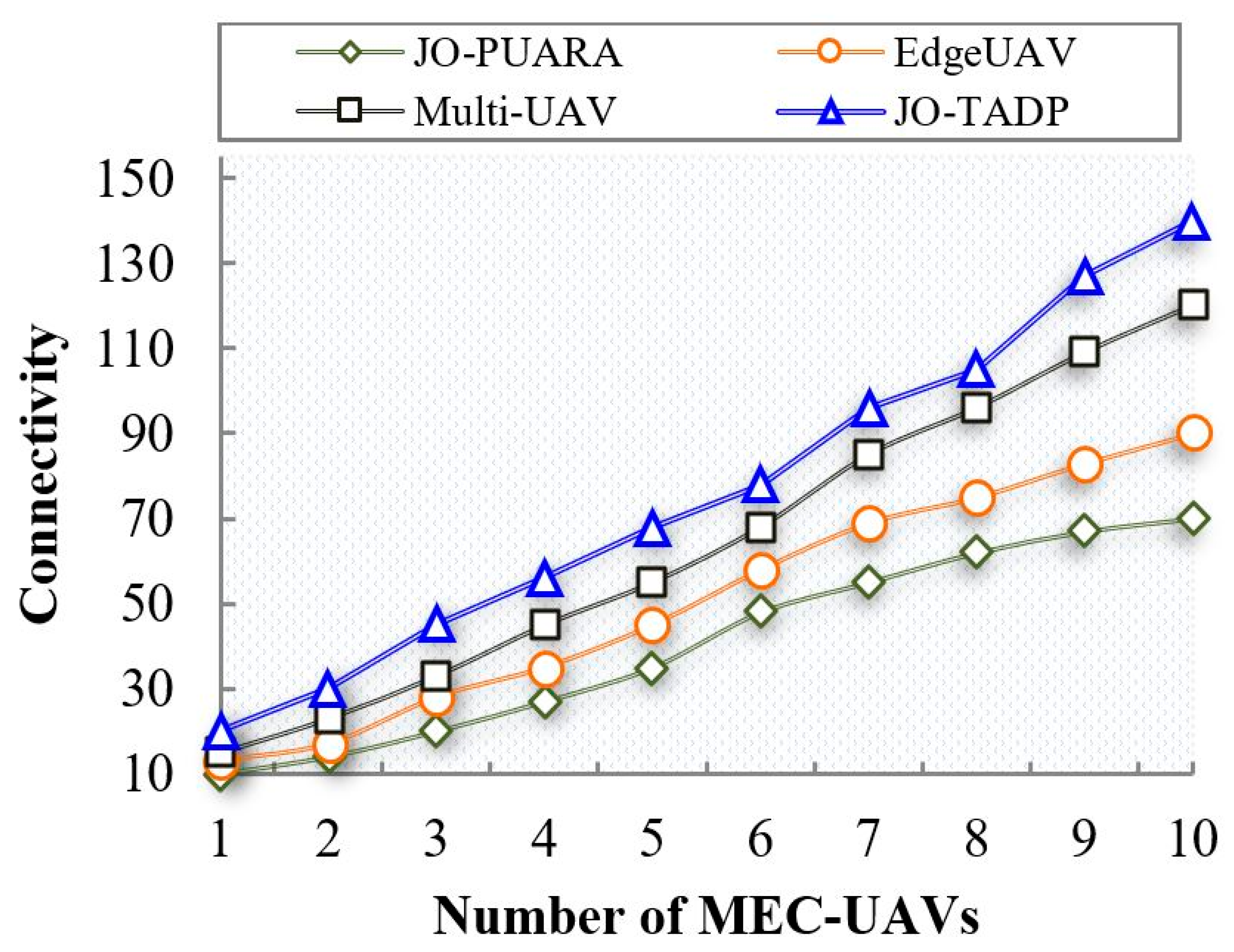
The connectivity metric is defined by the range that the MEC–UAVs provide resilient and reliable services to the underlying MUs. Figure 5 illustrates a comparison of connectivity between the proposed JO-TADP and existing works regarding MEC–UAV connectivity. When the maximum number of MEC–UAVs are placed, i.e., 10, the proposed work achieves the connectivity of 140. In contrast, the existing works such as JO-PUARA, EdgeUAVs, and Multi-UAV achieve the connectivity for the same number of MEC–UAVs 70, 90, and 120, respectively. From that, it can be noticed that the proposed work gains better connectivity than the existing works.
The proposed scheme achieves high connectivity as it performs DL-based trajectory planning and altitude optimization. SSIA-LSTM considers several key parameters, such as the history of weather records, speed and energy of MEC–UAVs, mobility model of MEC–UAVs, and kinematic properties, which are provided as input to the SSIA-LSTM algorithm for predicting future trajectory path and altitude optimization. These parameters are used as input to the SSIA-LSTM algorithm, which performs trajectory planning, altitude optimization, and minimization of hovering time. The gated network in LSTM passes these parameters for predicting trajectory, altitude, and hovering time, therefore enhancing connectivity and reducing collision rates among MEC–UAVs. In contrast, the existing work for Multi-UAVs uses a hybrid DRL algorithm to provide connectivity but lacks trajectory and altitude optimization, leading to a higher collision rate and poor performance. The simulation results demonstrate that the proposed JO-TADP outperforms the existing JO-PUARA, EdgeUAVs, and Multi-UAV in terms of connectivity between MUs and MEC–UAVs.
6.2.2. Analysis of Energy Consumption
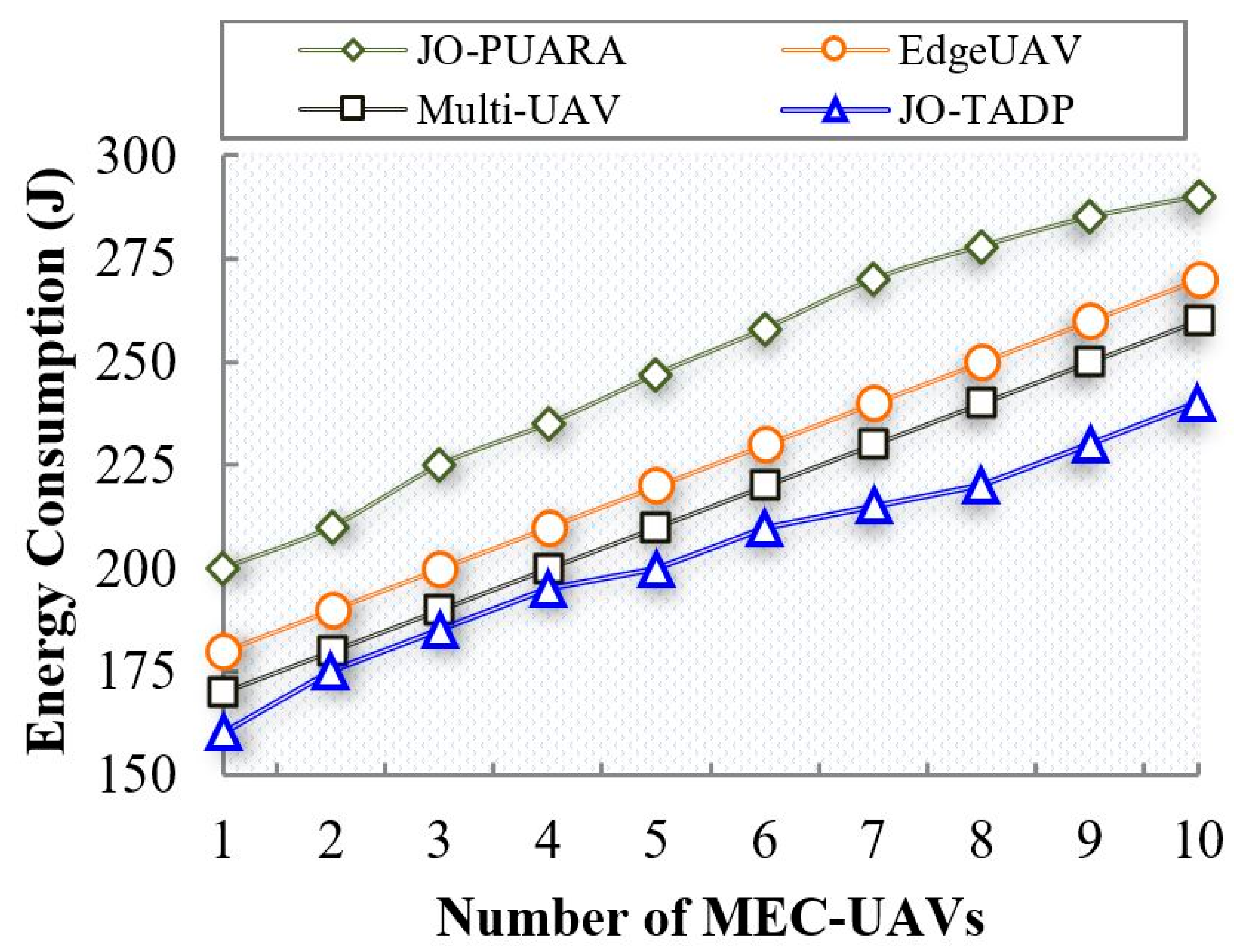
The comparison of energy consumption between the proposed JO-TADP and the existing works with respect to the number of MEC–UAVs is shown in Figure 6. When the number of MEC–UAVs is increased to 10, the energy consumption rate of the proposed JO-TADP is 240 J, whereas the energy consumption rates of the existing works JO-PUARA, EdgeUAVs, and Multi-UAV are 290 J, 270 J, and 260 J, respectively. The optimal allocation of MEC–UAVs and cooperative dynamic resource allocation is responsible for such a reduction in energy consumption. Unwanted energy consumption is reduced by optimizing the MEC–UAV allocation based on user density using the BLWO optimization algorithm.
Furthermore, energy consumption is also reduced by proposing cooperative resource allocation using an AFL method, in which the MU request classification and auction-based EDQN shared resource allocation are used to reduce the energy consumption of individual MEC–UAVs. However, the existing works adopt an energy consumption minimization method that fails to consider the deployment of UAVs and MU constraints, which results in higher energy consumption than the proposed work.
6.2.3. Analysis of Utility Rate
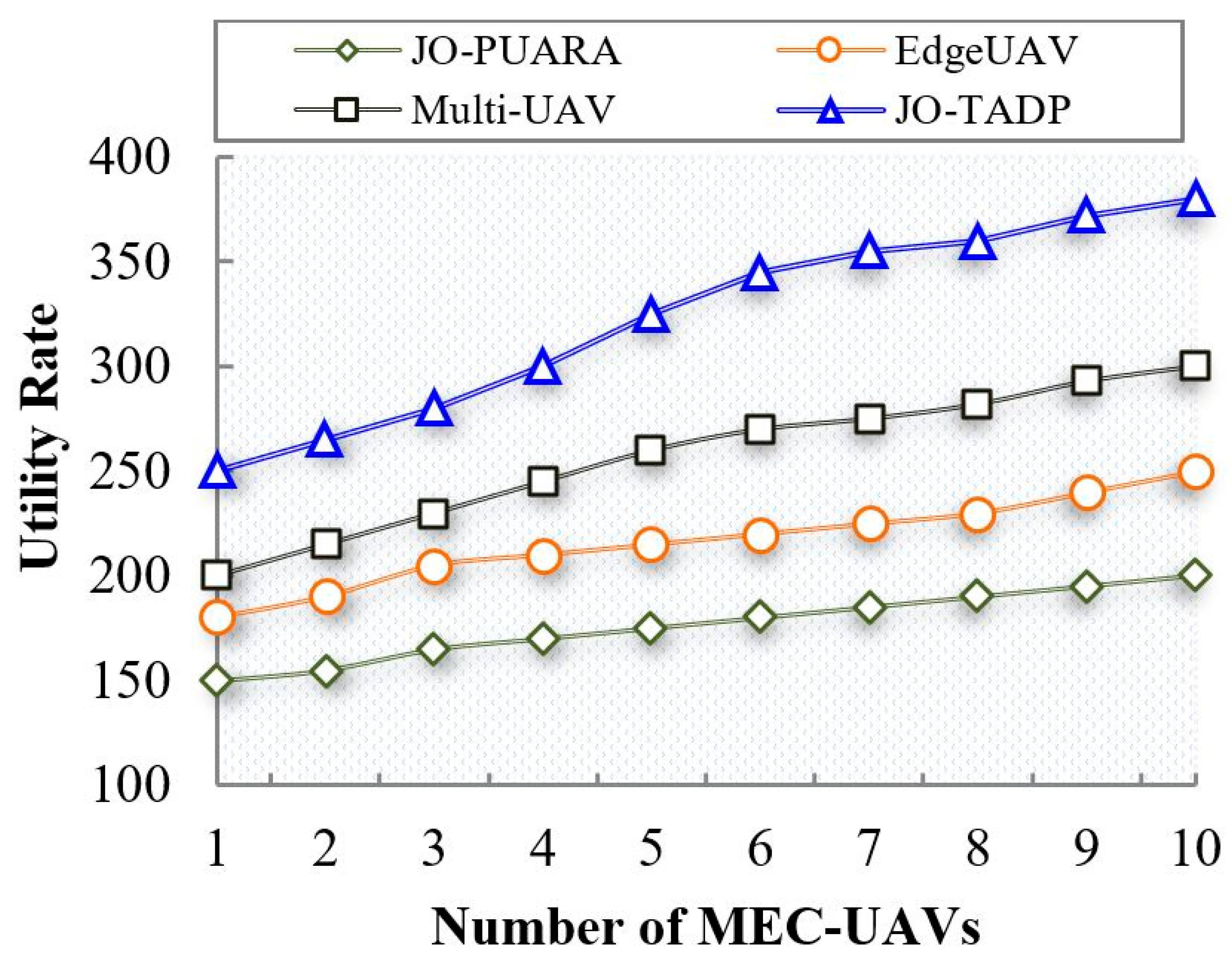
Figure 7 represents the utility rate comparison of proposed JO-TADP and existing works in terms of the number of MEC–UAVs. It can be noticed that when the number of MEC–UAVs increases to 10, the utility rate of the proposed work increases to 380, whereas the existing works JO-PUARA, EdgeUAVs, and Multi-UAV achieve lesser utility rates of 200, 250, and 300, respectively. The major reason for such a higher utility rate is that the proposed MEC–UAVs use their resources by adopting three agents, namely TPA, LUA, and RAA, for trajectory and altitude planning, handling MU requests, and resource allocation, respectively.
In addition, the proposed work splits the available channel’s bandwidth into two levels, i.e., familiar and non-familiar levels for resource allocation, therefore achieving a higher utility rate. In contrast, the existing works lack optimal management of resources in the given scenario, leading to resource wastage and lower utility rates than the proposed work.
6.2.4. Analysis of Data Rate
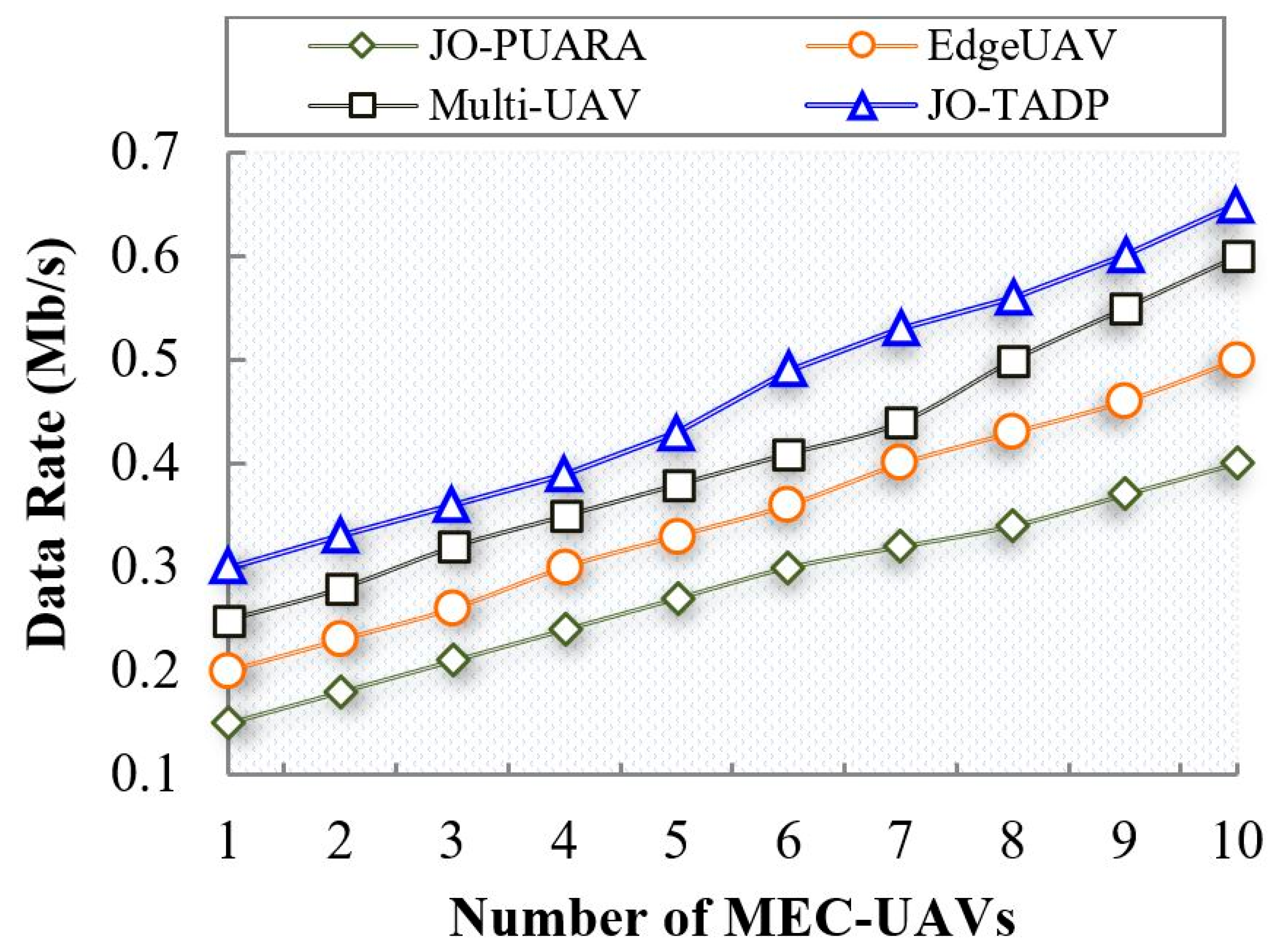
Figure 8 illustrates the data rate comparison between the proposed JO-TADP and the existing works in terms of the number of MEC–UAVs. The graph demonstrates that when the number of MEC–UAVs reaches 10, the data rate of the proposed work increases to 0.65 Mb/s, while the existing works JO-PUARA, EdgeUAVs, and Multi-UAV achieve data rates of 0.4, 0.5, and 0.6 Mb/s, respectively. The higher data rate is because the MEC–UAVs in the environment are optimally allocated using the BLWO algorithm, which increases connectivity and data rate. Furthermore, the MEC–UAV trajectory and altitude are optimally adjusted using SSIA-LSTM based on several parameters, which increases the data rate by reducing collision. The existing approaches are limited in terms of UAV allocation and collision management, which ultimately leads to a decrease in data rates.
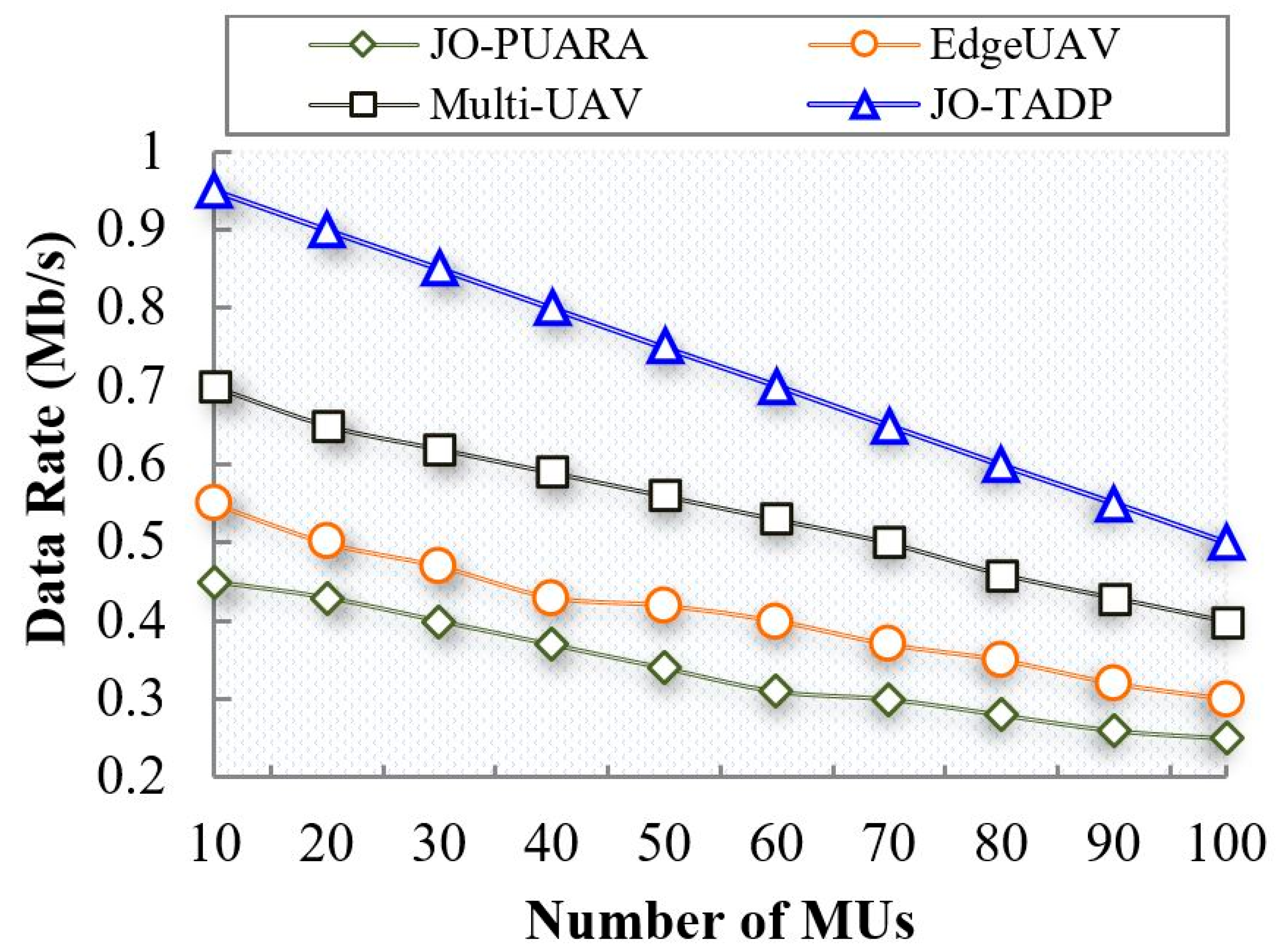
Similarly, Figure 9 provides the comparison results of data rate between the proposed JO-TADP and the existing works with respect to the number of MUs. It can be seen that when the number of MUs reaches 100, the data rates decrease to 0.5 Mb/s, whereas the existing works JO-PUARA, EdgeUAVs, and Multi-UAV achieve data rates of 0.25, 0.3, and 0.4 Mb/s, respectively, which are lower than the proposed work. The proposed work achieves higher data rates even though the number of MUs increases in the environment. The reason for such higher data rates is that the proposed scheme performs MU clustering based on MU mobility using the TM-DPC algorithm. MU Clustering reduces energy consumption, increasing data rate. Furthermore, the clusters are effectively managed through cluster merging and splitting. However, the previous studies lacked MU management, resulting in lower data rates than the proposed work.
6.2.5. Analysis of Delay Time
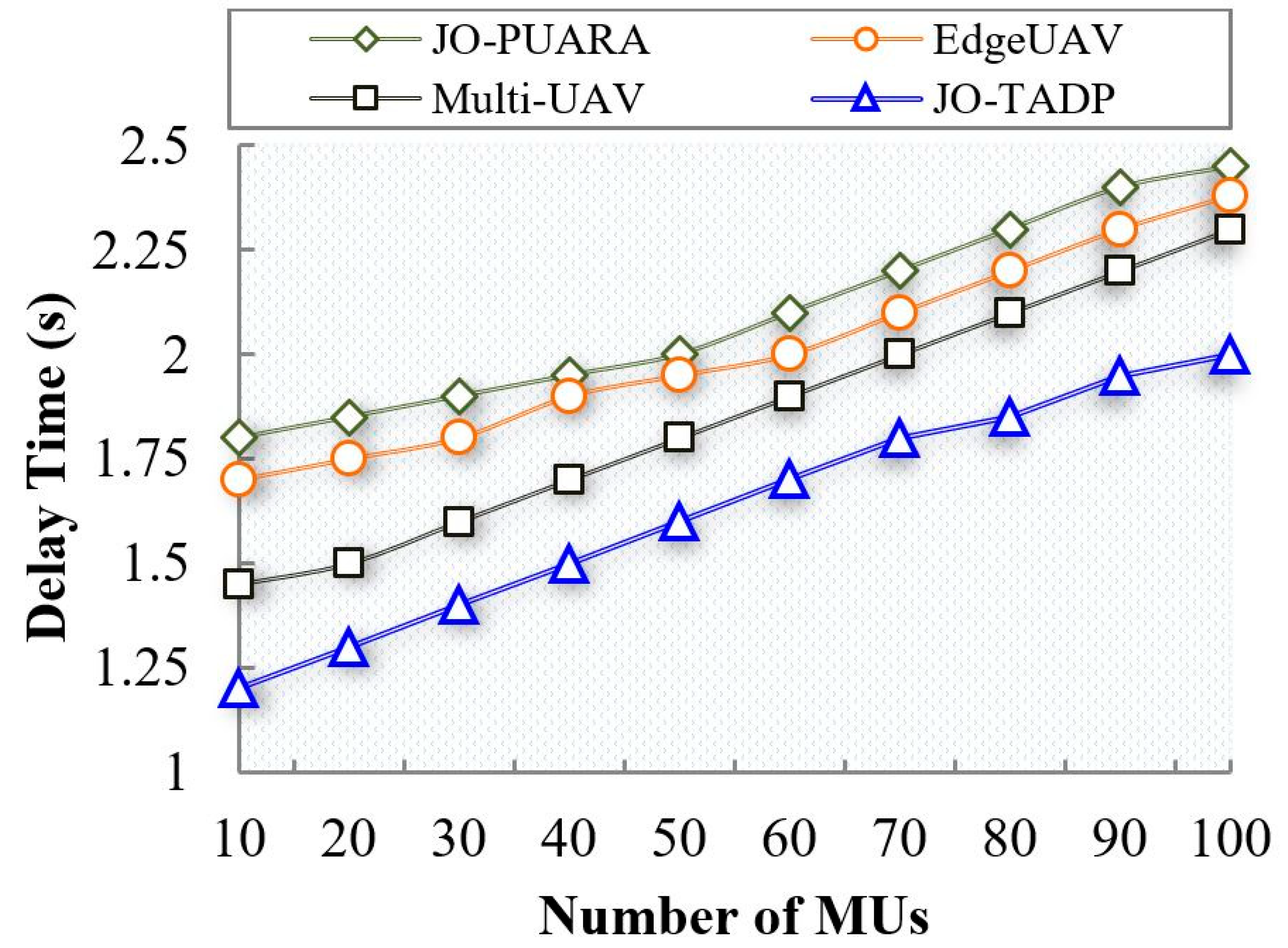
Figure 10 depicts the delay comparison between the proposed JO-TADP and the existing works in terms of the number of MUs. It can be noticed that when the number of MUs increases to 100, the delay time increases to 2 s. In contrast, the existing works JO-PUARA, Edge UAVs, and Multi-UAV achieve delays of 2.45 s, 2.38 s, and 2.3 s, respectively, higher than the proposed method.
The results show that the proposed work reduces delay time, even when the number of MUs increases in the environment. The proposed method leverages mobility-aware clustering using the TM-DPC algorithm, which effectively handles the mobility of MUs and enhances their association with MEC–UAVs. This, in turn, reduces delay time and improves communication efficiency between MUs and MEC–UAVs. In contrast, the existing approaches fail to adequately address the dynamic nature of MUs in their environment. This limitation results in decreased associativity between MUs, leading to increased delay time in communication.
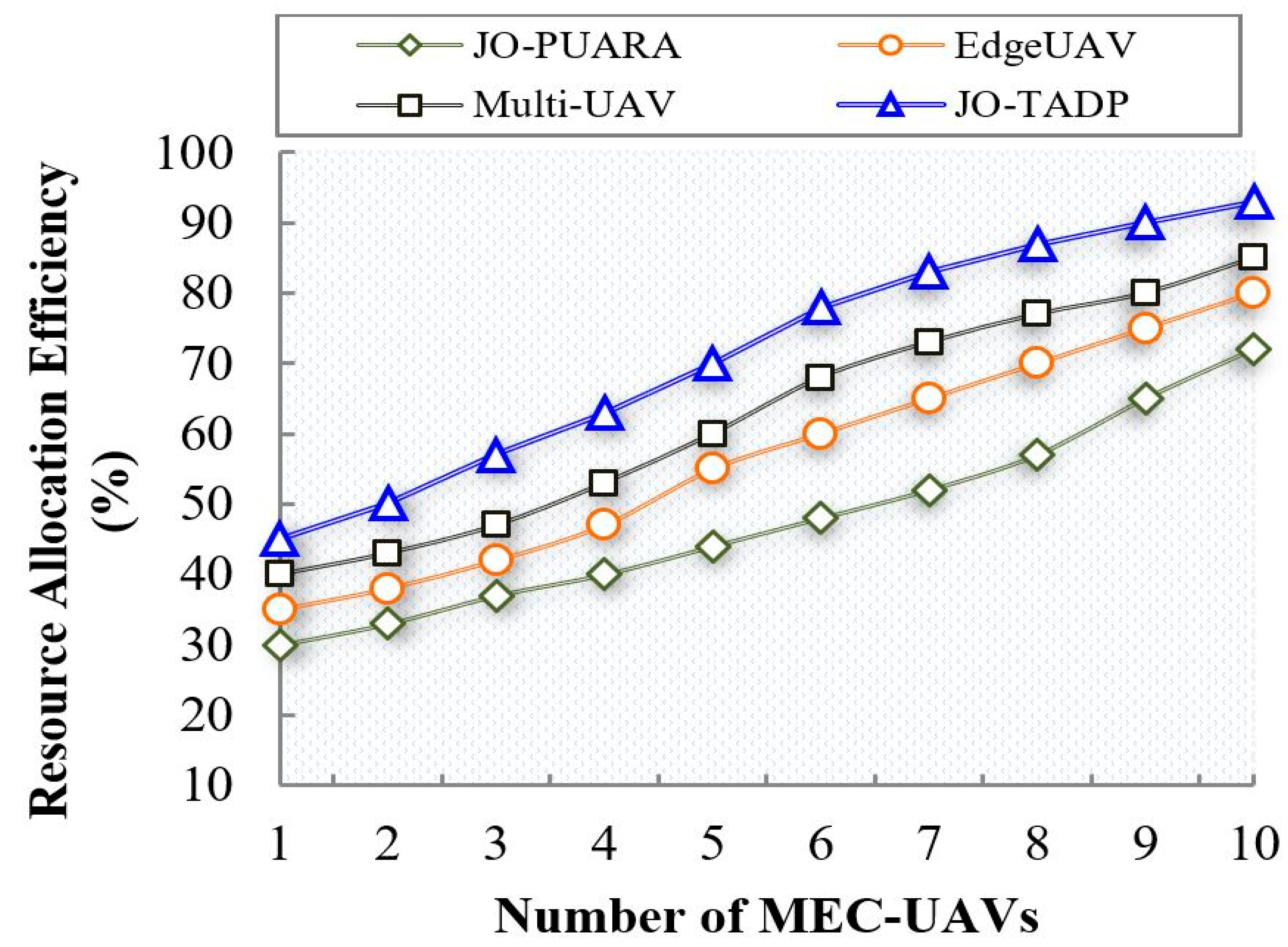
6.2.6. Analysis of Resource Allocation Efficiency
Figure 11 plots the comparison results of efficient resource allocation between the proposed JO-TADP and the existing approaches with respect to the number of MEC–UAVs. The simulation results illustrate that the resource allocation efficiency increases as the number of MEC–UAVs; however, it can be seen that the proposed JO-TADP outperforms the existing JO-PUARA, EdgeUAVs, and Multi-UAV approaches. The primary reason for achieving higher resource allocation efficiency for the proposed scheme is that it adopts an AFL and auction-based DRL method, which reduces the complexity burden by independently allowing the MUs for resource allocation. The MTPSWM is used for request classification and EDQN with an auction mechanism for shared resource allocation to the MUs. In contrast, the existing works limit resource allocation efficiency as they do not compensate for the MEC–UAVs and the MU constraints.
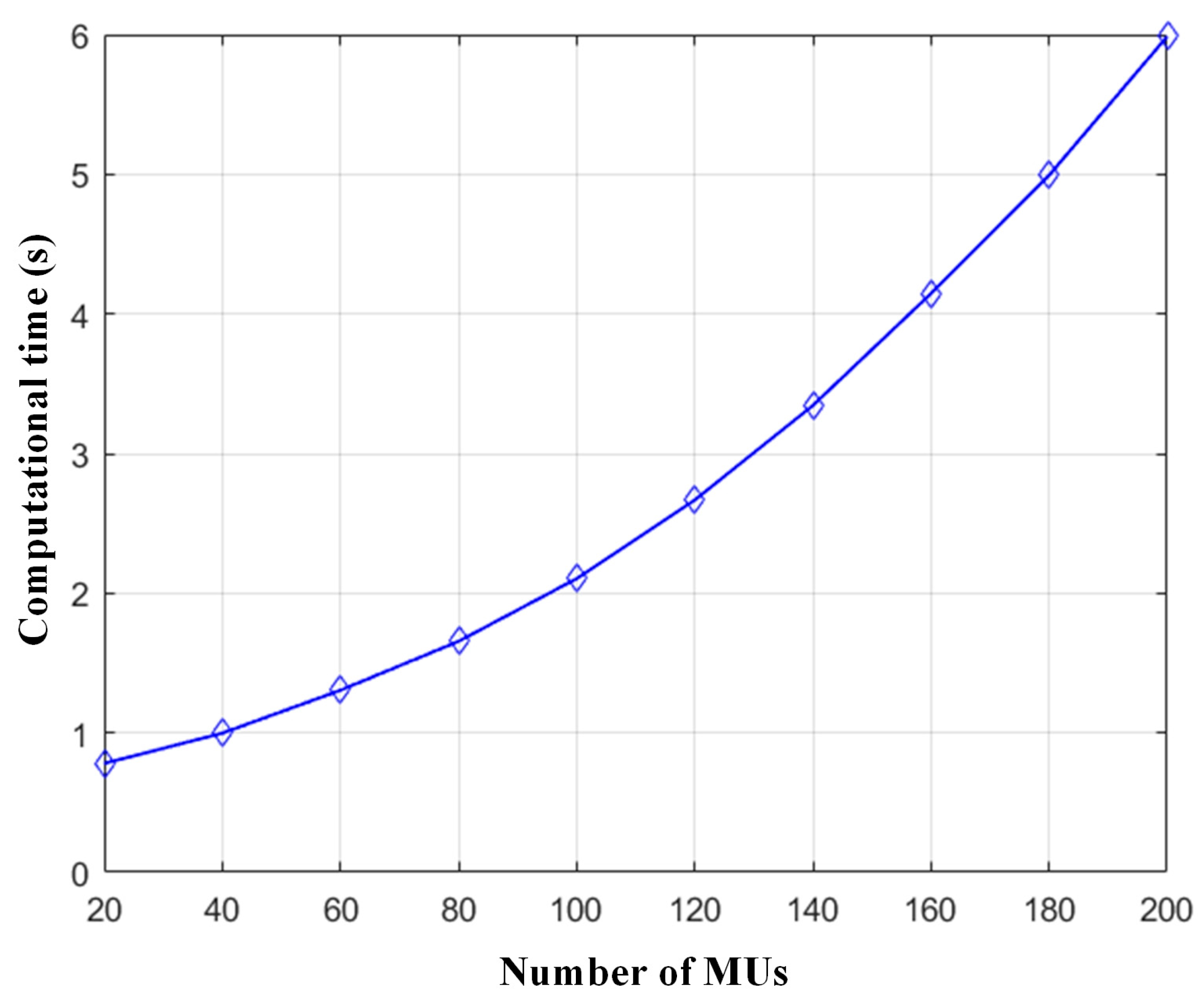
The computation complexity of the proposed optimum MEC–UAV allocation is , where is the number of MEC–UAVs, is the number of users, is the maximum iteration. The computational complexity of proposed Algorithm 2 is , where represent the number of layers, size of the input layer, and size of each layer of the network. The asymptotic complexity of Algorithm 3 is where denotes the number of iterations, is the number of MEC–UAVs, is the number of users. Figure 12 represents the computational time of the proposed approach with respect to the number of MUs.
6.3. Summary
This section provides an overview of the proposed JO-TADP experimental results. The simulation results from the comparative graphs Figure 5, Figure 6, Figure 7, Figure 8, Figure 9, Figure 10 and Figure 11, show that the proposed work outperforms the existing schemes. The optimum MEC–UAV allocation strategy addresses unwanted energy consumption and connectivity issues using an optimization algorithm. Furthermore, the energy consumption and connectivity improved by performing DL-based autonomous trajectory planning and altitude optimization, increasing the hovering time of MEC–UAVs. The energy consumption of the MUs is reduced by using the mobility-aware clustering algorithm. MEC–UAV available bandwidth is split into two levels, familiar and non-familiar. Finally, the tasks of MUs are classified as familiar and non-familiar resources using MTNP-SVM, and optimal resources are allocated by performing auction-based cooperative dynamic an AFL using the DRL algorithm. The average numerical results of the proposed scheme and existing schemes are summarized in Table 6.
7. Conclusions and Future Works
High energy consumption, lack of connectivity, and poor resource allocation are the major problems faced by UAV-enabled wireless networks. The proposed architecture comprises MUs, MEC–UAVs, GBS, and a UAV controller, in which the MEC–UAVs use three learning agents named TPA, LUA, and RAA to enhance resource allocation. At the initial stage, the UAV controller optimally allocates the MEC–UAVs based on the density of MUs using the BLWO algorithm. Second, the MU’s constraints, such as energy consumption and dynamicity, are ensured by clustering using the TM-DPC algorithm based on the mobility of MUs. The CHs are selected based on the mobility and stability of the MUs. Furthermore, the clusters are managed optimally by cluster formation and splitting. At the same time, the MEC–UAV altitude, trajectory, and hover time are optimized jointly using the SSIA-LSTM algorithm. Finally, the bandwidth resources of MEC–UAVs are split into two levels, namely familiar and non-familiar, MTNP-SVM is applied to categorize MU tasks as familiar or non-familiar resources. The dynamic cooperative resource allocation is made by the MEC–UAVs for MUs using an AFL-based CSACFPN (for local model generation) and EDQN (for shared global model generation). The simulation results show that the proposed work outperforms the existing approaches.
As a future initiative, it is essential to consider the security and privacy parameter while allocating resources in an edge-assisted UAV environment. Furthermore, focusing on other resource scheduling during resource allocation will be worth future study.
Author Contributions
Paper Writing—Original Draft Preparation, S.A.; Writing—Review and Editing, J.Z., U.A.K. and A.K.; Methodology, S.A.; Software, S.A.; Formal analysis, S.A. and A.K.; Validation, S.A. and A.K.; Data Curation, U.A.K.; Investigation, B.H. All authors agreed to submit this article for publication in MDPI drones. All authors have read and agreed to the published version of the manuscript.
Funding
This work was supported by the National Natural Science Foundation of China (Grant No. 62271063), the National Key Laboratory of Science and Technology on Vacuum Electronics, and the Director Fund of Beijing Key Laboratory of Space-ground Interconnection and Convergence.
Data Availability Statement
Not applicable.
Conflicts of Interest
The authors declare no conflict of interest.
References
- Dujuan, H. Mobile Communication Technology of Sports Events in 5G era. Microprocess. Microsyst. 2020, 80, 103331. [Google Scholar] [CrossRef]
- Ahmed, S.; Ameen, S.Y.; Zeebaree, S.R. 5G Mobile Communication System Performance Improvement with Caching: A Review. In Proceedings of the International Conference of Modern Trends in Information and Communication Technology Industry (MTICTI), Sana’a, Yemen, 4–6 December 2021; pp. 1–8. [Google Scholar]
- Zhang, J.A.; Rahman, M.L.; Wu, K.; Huang, X.; Guo, Y.J.; Chen, S.; Yuan, J. Enabling Joint Communication and Radar Sensing in Mobile Networks—A Survey. IEEE Commun. Surv. Tutor. 2020, 24, 306–345. [Google Scholar] [CrossRef]
- Khan, A.; Zhang, J.; Ahmad, S.; Memon, S.; Qureshi, H.A.; Ishfaq, M. Dynamic Positioning and Energy-Efficient Path Planning for Disaster Scenarios in 5G-Assisted Multi-UAV Environments. Electronics 2022, 11, 2197. [Google Scholar] [CrossRef]
- Kurniawan, I.F.; Asyhari, A.T.; He, F.; Liu, Y. Mobile Computing and Communications-Driven Fog-Assisted Disaster Evacuation Techniques for Context-Aware Guidance Support: A survey. Comput. Commun 2021, 179, 195–216. [Google Scholar] [CrossRef]
- Jung, S.; Yun, W.J.; Kim, J.; Kim, J. Coordinated Multi-Agent Deep Reinforcement Learning for Energy-Aware UAV-Based Big-Data Platforms. Electronics 2021, 10, 543. [Google Scholar] [CrossRef]
- Taleb, T.; Ksentini, A.; Hellaoui, H.; Bekkouche, O. On Supporting UAV Based Services in 5G and Beyond Mobile Systems. IEEE Netw. 2021, 35, 220–227. [Google Scholar] [CrossRef]
- Singhal, C.; Chandana, B.N. Aerial-SON: UAV-based Self-Organizing Network for Video Streaming in Dense Urban Scenario. In Proceedings of the International Conference on Communication Systems & NetworkS (COMSNETS), Bangalore, India, 5–9 January 2021; pp. 7–12. [Google Scholar]
- Kim, S.; Kim, Y. An Energy Efficient UAV-Based Edge Computing System with Reliability Guarantee for Mobile Ground Nodes. Sensors 2021, 21, 8264. [Google Scholar] [CrossRef]
- Islam, N.; Rashid, M.M.; Pasandideh, F.; Ray, B.R.; Moore, S.T.; Kadel, R. A Review of Applications and Communication Technologies for Internet of Things (IoT) and Unmanned Aerial Vehicle (UAV) Based Sustainable Smart Farming. Sustainability 2021, 13, 1821. [Google Scholar] [CrossRef]
- McEnroe, P.; Wang, S.; Liyanage, M. A Survey on the Convergence of Edge Computing and AI for UAVs: Opportunities and Challenges. IEEE Internet Things J. 2022, 9, 15435–15459. [Google Scholar] [CrossRef]
- Ren, J.; Yu, G.; He, Y.; Li, G.Y. Collaborative cloud and edge computing for latency minimization. IEEE Trans. Veh. Technol. 2019, 68, 5031–5044. [Google Scholar] [CrossRef]
- Khan, A.; Zhang, J.; Ahmad, S.; Memon, S.; Hayat, B.; Rafiq, A. Dqn-based Proactive Trajectory Planning of UAVs in Multi-access edge computing. Comput. Mater. Contin. 2023, 74, 4685–4702. [Google Scholar] [CrossRef]
- Wang, J.; Ma, Y.; Lu, R.; Wang, J.; Lin, M.; Cheng, J. Hovering UAV-Based FSO Communications: Channel Modelling, Performance Analysis, and Parameter Optimization. IEEE J. Sel. Areas Commun. 2021, 39, 2946–2959. [Google Scholar] [CrossRef]
- Qian, Y. Unmanned aerial vehicles and multi-access edge computing. IEEE Wirel. Commun. 2021, 28, 2–3. [Google Scholar] [CrossRef]
- Liu, Z.; Cao, Y.; Gao, P.; Hua, X.; Zhang, D.; Jiang, T. Multi-UAV network assisted intelligent edge computing: Challenges and opportunities. China Commun. 2022, 19, 258–278. [Google Scholar] [CrossRef]
- Niculescu, V.; Palossi, D.; Magno, M.; Benini, L. Fly, Wake-up, Find: UAV-based Energy-efficient Localization for Distributed Sensor Nodes. Sustain. Comput. Inform. Syst. 2022, 34, 100666. [Google Scholar] [CrossRef]
- He, X.; Jin, R.; Dai, H. Joint Service Placement and Resource Allocation for Multi-UAV Collaborative Edge Computing. In Proceedings of the IEEE Wireless Communications and Networking Conference (WCNC), Nanjing, China, 29 March–1 April 2021; pp. 1–6. [Google Scholar]
- He, X.; Li, X.; Ji, H.; Zhang, H. Resource Allocation for Secrecy Rate Optimization in UAV-assisted Cognitive Radio Network. In Proceedings of the IEEE Wireless Communications and Networking Conference (WCNC), Nanjing, China, 29 March–1 April 2021; pp. 1–6. [Google Scholar]
- Li, K.; Ni, W.; Kurunathan, H.; Dressler, F. Data-driven Deep Reinforcement Learning for Online Flight Resource Allocation in UAV-aided Wireless Powered Sensor Networks. In Proceedings of the ICC—IEEE International Conference on Communications, Seoul, Republic of Korea, 16–20 May 2022; pp. 1–6. [Google Scholar]
- Nie, Y.; Zhao, J.; Gao, F.; Yu, F.R. Semi-Distributed Resource Management in UAV-Aided MEC Systems: A Multi-Agent Federated Reinforcement Learning Approach. IEEE Trans. Veh. Technol. 2021, 70, 13162–13173. [Google Scholar] [CrossRef]
- Peng, Y.; Liu, Y.; Zhang, H. Deep Reinforcement Learning based Path Planning for UAV-assisted Edge Computing Networks. In Proceedings of the IEEE Wireless Communications and Networking Conference (WCNC), Nanjing, China, 29 March–1 April 2021; pp. 1–6. [Google Scholar]
- Tun, Y.K.; Dang, T.N.; Kim, K.; Alsenwi, M.; Saad, W.; Hong, C.S. Collaboration in the Sky: A Distributed Framework for Task Offloading and Resource Allocation in Multi-Access Edge Computing. IEEE Internet Things J. 2021, 9, 24221–24235. [Google Scholar] [CrossRef]
- Zhai, D.; Li, H.; Tang, X.; Zhang, R.; Cao, H. Joint Position Optimization, User Association, and Resource Allocation for load Balancing in UAV-assisted Wireless Networks. Digit. Commun. Netw. 2022. [Google Scholar] [CrossRef]
- Cheng, Z.; Liwang, M.; Chen, N.; Huang, L.; Guizani, N.; Du, X. Learning-based User Association and Dynamic Resource Allocation in Multi-Connectivity Enabled Unmanned Aerial Vehicle Networks. Digit. Commun. Netw. 2022. [Google Scholar] [CrossRef]
- Yang, H.; Zhao, J.; Xiong, Z.; Lam, K.; Sun, S.; Xiao, L. Privacy-Preserving Federated Learning for UAV-Enabled Networks: Learning-Based Joint Scheduling and Resource Management. IEEE J. Sel. Areas Commun. 2020, 39, 3144–3159. [Google Scholar] [CrossRef]
- Tran, D.; Nguyen, V.; Gautam, S.; Chatzinotas, S.; Vu, T.X.; Ottersten, B.E. UAV Relay-Assisted Emergency Communications in IoT Networks: Resource Allocation and Trajectory Optimization. IEEE Trans. Wirel. Commun. 2020, 21, 1621–1637. [Google Scholar] [CrossRef]
- Chen, X.; Liu, X.; Chen, Y.; Jiao, L.; Min, G. Deep Q-Network based Resource Allocation for UAV-assisted Ultra-Dense Networks. Comput. Networks 2021, 196, 108249. [Google Scholar] [CrossRef]
- Wang, Z.; Wen, M.; Dang, S.; Yu, L.; Wang, Y. Trajectory Design and Resource Allocation for UAV Energy Minimization in a Rotary-wing UAV-enabled WPCN. Alex. Eng. J. 2021, 60, 1787–1796. [Google Scholar] [CrossRef]
- Manzoor, A.; Kim, K.; Pandey, S.R.; Kazmi, S.M.; Tran, N.H.; Saad, W.; Hong, C.S. Ruin Theory for Energy-Efficient Resource Allocation in UAV-Assisted Cellular Networks. IEEE Trans. Commun. 2021, 69, 3943–3956. [Google Scholar] [CrossRef]
- Li, Y.; Zhang, H.; Long, K.; Jiang, C.; Guizani, M. Joint Resource Allocation and Trajectory Optimization with QoS in UAV-Based NOMA Wireless Networks. IEEE Trans. Wirel. Commun. 2021, 20, 6343–6355. [Google Scholar] [CrossRef]
- Do-Duy, T.; Nguyen, L.D.; Duong, T.Q.; Khosravirad, S.R.; Claussen, H. Joint Optimisation of Real-Time Deployment and Resource Allocation for UAV-Aided Disaster Emergency Communications. IEEE J. Sel. Areas Commun. 2021, 39, 3411–3424. [Google Scholar] [CrossRef]
- Luong, P.; Gagnon, F.; Tran, L.; Labeau, F. Deep Reinforcement Learning-Based Resource Allocation in Cooperative UAV-Assisted Wireless Networks. IEEE Trans. Wirel. Commun. 2021, 20, 7610–7625. [Google Scholar] [CrossRef]
- Seid, A.M.; Boateng, G.O.; Anokye, S.; Kwantwi, T.; Sun, G.; Liu, G. Collaborative Computation Offloading and Resource Allocation in Multi-UAV-Assisted IoT Networks: A Deep Reinforcement Learning Approach. IEEE Internet Things J. 2021, 8, 12203–12218. [Google Scholar] [CrossRef]
- Cao, H.; Hu, Y.; Yang, L. Towards intelligent virtual resource allocation in UAVs-assisted 5G networks. Comput. Netw. 2020, 185, 107660. [Google Scholar] [CrossRef]
- Niu, H.; Zhao, X.; Li, J. 3D Location and Resource Allocation Optimization for UAV-Enabled Emergency Networks Under Statistical QoS Constraint. IEEE Access 2021, 9, 41566–41576. [Google Scholar] [CrossRef]
- Chang, Z.; Deng, H.; You, L.; Min, G.; Garg, S.; Kaddoum, G. Trajectory Design and Resource Allocation for Multi-UAV Networks: Deep Reinforcement Learning Approaches. IEEE Trans. Netw. Sci. Eng. 2022, 1. [Google Scholar] [CrossRef]
- Ji, J.; Zhu, K.; Yi, C.; Niyato, D.T. Energy Consumption Minimization in UAV-Assisted Mobile-Edge Computing Systems: Joint Resource Allocation and Trajectory Design. IEEE Internet Things J. 2021, 8, 8570–8584. [Google Scholar] [CrossRef]
- Huang, J.; Xu, S.; Zhang, J.; Wu, Y. Resource Allocation and 3D Deployment of UAVs-Assisted MEC Network with Air-Ground Cooperation. Sensors 2022, 22, 2590. [Google Scholar] [CrossRef] [PubMed]
- Ei, N.N.; Alsenwi, M.; Tun, Y.K.; Han, Z.; Hong, C.S. Energy-Efficient Resource Allocation in Multi-UAV-Assisted Two-Stage Edge Computing for Beyond 5G Networks. IEEE Trans. Intell. Transp. Syst. 2020, 23, 16421–16432. [Google Scholar] [CrossRef]
- Xu, Y.; Zhang, T.; Liu, Y.; Yang, D.; Xiao, L.; Tao, M. UAV-Assisted MEC Networks with Aerial and Ground Cooperation. IEEE Trans. Wirel. Commun. 2021, 20, 7712–7727. [Google Scholar] [CrossRef]
- Tan, T.; Zhao, M.; Zeng, Z. Joint Offloading and Resource Allocation Based on UAV-Assisted Mobile Edge Computing. ACM Trans. Sens. Netw. 2022, 18, 1–21. [Google Scholar] [CrossRef]
- Cao, P.; Liu, Y.; Yang, C. Robust Resource Allocation and Trajectory Planning of UAV-Aided Mobile Edge Computing in Post-Disaster Areas. Appl. Sci. 2022, 12, 2226. [Google Scholar] [CrossRef]
- Correll, N.; Hayes, B.; Heckman, C.; Roncone, A. Introduction to Autonomous Robots: Mechanisms, Sensors, Actuators, and Algorithms; MIT Press: Cambridge, MA, USA, 2022. [Google Scholar]
- Yang, H.; Zhang, X.; Khanduri, P.; Liu, J. Anarchic Federated Learning. Int. Conf. Mach. Learn. 2022, 162, 25331–25363. [Google Scholar]
Figure 1.
The Overall Architecture of Proposed JO-TDAP-based Resource Allocation in MEC–UAV Networks.
Figure 1.
The Overall Architecture of Proposed JO-TDAP-based Resource Allocation in MEC–UAV Networks.

Figure 2.
TM-DPC Clustering.

Figure 3.
SSIA-LSTM-based trajectory and altitude optimization.

Figure 4.
EDQN-based Cooperative Shared Resource Allocation.

Figure 5.
Number of MEC–UAVs vs. connectivity.

Figure 6.
Number of MEC–UAVs vs. energy consumption.

Figure 7.
Number of MEC–UAVs vs. utility rate.

Figure 8.
Number of MEC–UAVs vs. data rate.

Figure 9.
Number of MUs vs. data rate.

Figure 10.
Number of MUs vs. delay time.

Figure 11.
Number of MEC–UAVs vs. resource allocation efficiency.

Figure 12.
Computational time with respect to the number of MUs.


Table 1.
Novelty highlights.
| Existing Methods | Proposed Novelties |
|---|---|
| The existing works deploy UAVs in the environment in a random manner for resource allocation, which leads to unwanted energy consumption and leads to poor connectivity issues. Even though they use 3D model deployment, this issue affects the performance of UAVs. | The proposed work mitigates that issue by deploying optimum MEC–UAVs based on the MU density. To increase the scalability and speed during optimum UAV allocation, we adopt a heuristics algorithm named BLWO algorithm. |
| Most existing works did not consider MU constraints regarding their mobility for resource allocation in UAV-based wireless networks. The MUs are not static, which leads to service discontinuity. | We reduce the service discontinuity rate by performing MU clustering using a novel clustering algorithm named TW-DPC for mobility control and user association. In addition, the clusters are optimally managed by clustering, splitting, and merging, respectively. |
| The existing approaches provide resource allocation using only limited strategies. Specifically, they either optimize trajectory and resource allocation or user association and resource allocation, affecting resource allocation efficiency. | In this paper, we jointly optimize the trajectory, delay, altitude, and power of the MEC–UAVs. Furthermore, we have proposed a cooperative dynamic resource allocation method using an AFL algorithm. |
Table 2.
Summary of notations.
| Notation | Definition |
|---|---|
| MEC–UAVs | |
| MUs | |
| Channel sets of MEC–UAVs | |
| , | Bandwidth of familiar and non-familiar resources |
| Resource request | |
| E, D, P, C | Energy, delay, power, and computation optimization |
| TR, AL | Trajectory and altitude optimization |
| Optimization constant | |
| User association | |
| Hovering energy consumption | |
| Hovering power consumption | |
| Harmonization factor | |
| Local density | |
| Euclidean distance among two MUs | |
| Positive cluster region | |
| Evidence theory co-efficient | |
| Jerk of MEC–UAVs | |
| Val | Value |
| MTNP-SVM hyperplane constant | |
| L2 regularization function |
Table 3.
Literature survey.
| Existing Methods | Reference | Objective | Algorithms/ Methods | Resource Allocation Strategies | Limitations | ||||||
|---|---|---|---|---|---|---|---|---|---|---|---|
| UAV-Alloc | TR | AL | DM | PO | UA | CO | |||||
| UAV-assisted Resource Allocation | [24] | To increase the sum rate of all the MUs in UAV-based wireless networks | Branch and Bound Method | 🗶 | 🗶 | 🗶 | 🗶 | ✔ | ✔ | 🗶 | Resource Disruption, High Energy Consumption |
| [25] | To achieve optimal resource allocation in multi-connectivity UAV networks | DRL | ✔ | 🗶 | 🗶 | 🗶 | 🗶 | ✔ | 🗶 | Deprived user connectivity, Inefficient resource allocation | |
| [26] | To preserve the privacy of the UAV-enabled MUs during resource allocation | FL, A3C algorithm | ✔ | 🗶 | 🗶 | 🗶 | 🗶 | ✔ | 🗶 | Less network lifetime, Delayed service provisioning | |
| [27] | To enable a conjoined resource allocation for UAV-based IoT networks | Iterative Algorithm | 🗶 | ✔ | 🗶 | 🗶 | 🗶 | 🗶 | 🗶 | Inefficient service provisioning | |
| [28] | To achieve energy-efficient resource allocation for ultra-dense UAV networks | MDP-based DQN | 🗶 | 🗶 | 🗶 | 🗶 | ✔ | ✔ | 🗶 | Less Stability | |
| [29] | To achieve the joint optimal resource allocation for UAV-enabled WPCN | Iterative Algorithm | 🗶 | ✔ | 🗶 | ✔ | ✔ | ✔ | 🗶 | Experiences unwanted energy consumption | |
| [30] | To achieve energy-constrained resource allocation for cellular-based UAV | Water-filling algorithm and ruin theory | 🗶 | 🗶 | 🗶 | ✔ | ✔ | ✔ | 🗶 | Unable to handle more user density | |
| [31] | To increase the QoS and resource allocation efficiency by NOMA-based UAV networks | Heuristic Algorithm | 🗶 | ✔ | 🗶 | 🗶 | ✔ | 🗶 | 🗶 | Easily trapped with local minima and convergence problems | |
| [32] | To enhance the communication capability of UAVs by combined solutions | K-means Clustering Algorithm | ✔ | ✔ | 🗶 | 🗶 | ✔ | 🗶 | 🗶 | Increased complexity | |
| [33] | To increase the sum rate by enabling collaborative resource allocation using UAV | DQN and Convex Algorithm | ✔ | 🗶 | 🗶 | 🗶 | ✔ | ✔ | 🗶 | Unwanted energy consumption and poor connectivity | |
| [34] | To achieve collaborative resource allocation by multiple UAV-based IoT networks | Clustering and DDPG algorithm | 🗶 | 🗶 | 🗶 | ✔ | 🗶 | 🗶 | ✔ | Poor service provisioning | |
| [35] | To enable resource allocation in a virtual manner using 5G-based UAV networks | Two-stage resource allocation method | 🗶 | 🗶 | 🗶 | 🗶 | ✔ | ✔ | 🗶 | Ineffective resource allocation | |
| [36] | To improve the message efficiency by enabling 3D-based UAV resource allocation | Iterative Algorithm | ✔ | 🗶 | 🗶 | ✔ | ✔ | 🗶 | 🗶 | High collision rate and unwanted hovering | |
| [37] | To improve the coverage by enabling multiple UAV-based resource allocation | DQN algorithm | 🗶 | ✔ | 🗶 | ✔ | 🗶 | 🗶 | 🗶 | Poor coverage rate | |
| MEC–UAV-Assisted Resource Allocation | [38] | To reduce the resource allocation rate by MEC-based UAV resource allocation methods | Combined Resource Allocation Method | 🗶 | ✔ | 🗶 | 🗶 | ✔ | 🗶 | ✔ | Ineffective resource allocation and service provisioning, Poor trajectory optimization |
| [39] | To improve the resource allocation efficiency by 3D deployment in MEC-based UAV networks | Iterative Algorithm | ✔ | 🗶 | ✔ | ✔ | 🗶 | ✔ | 🗶 | Service discontinuity, Unwanted energy consumption | |
| [40] | To enhance the resource allocation efficiency by multiple UAV-based 5G MEC networks | Two-stage method and block successive upper bound minimization algorithm | 🗶 | 🗶 | 🗶 | ✔ | 🗶 | 🗶 | ✔ | Increased energy consumption | |
| [41] | To improve the connectivity among MUs and UAVs using MEC | Convex and Lagrange-based Methods | 🗶 | ✔ | 🗶 | ✔ | ✔ | ✔ | 🗶 | Experiencing poor coverage | |
| [42] | To enhance reliability by enabling combined offloading in MEC-based UAV networks | Power rate semi-qualitative relaxation method and Position optimization algorithm | ✔ | 🗶 | 🗶 | 🗶 | 🗶 | ✔ | ✔ | Lack of considering optimal user metrics | |
| [43] | To improve the connectivity in disaster areas by MEC-based UAVs | Iterative Algorithm and Lagrange Method | 🗶 | ✔ | 🗶 | 🗶 | ✔ | 🗶 | 🗶 | Lack of resilient coverage affects the connectivity | |
| Proposed Work JO-TADP | To improve the fairness and energy efficiency of MEC-assisted UAV networks | Optimization algorithm, Clustering algorithm, Deep learning algorithm, and DRL algorithm | ✔ | ✔ | ✔ | ✔ | ✔ | ✔ | ✔ | Less energy consumption, High connectivity, Less delay, Increased reliability | |
UAV-Alloc—UAV Allocation, TR—Trajectory Optimization, AL—Altitude Optimization, DM—Delay Minimization, PO—Power Optimization, UA—User Association, CO—Computation Offloading.
Table 4.
AFL properties.
| Entities in AFL | Properties |
|---|---|
| Global Server (Global model generator) |
|
| Clients (Local model generator) |
|
Table 5.
Simulation configuration.
| Simulation and Network Parameters | Values |
|---|---|
| No. of MUs | 100 |
| No. of MEC–UAVs | 10 |
| No. of 5G GBS | 1 |
| No. of UAV controllers | 1 |
| Bandwidth | 2 MHz |
| Radius of the cell | [250, 350, 550, 850, 1050] |
| Average sensing radius of MEC–UAVs | 300 m |
| Minimum and Maximum height of MEC–UAVs | 40–140m |
| Carrier frequency | 3 GHz |
| Mobility model | Random waypoint |
| Area of simulation | 1500 m × 1500 m |
| Transmission power of MEC–UAVs | 30 dBm |
| Velocity of MEC–UAVs | ≈30 km/h |
| Velocity of MUs | 7 km/h |
| Slot for resource allocation | 25 ms |
| Interval of updation | 1.5 s |
| Size of the data | 50 MB |
| Noise of the MEC–UAVs | 10 dB |
| Path loss exponent and constant [24,38] | 3 and 1.54 × 10⁻⁵ |
| Loss due to air propagation | 0 dB |
| Loss in the free space | 33 dB |
Table 6.
Average numerical results of the proposed scheme and existing schemes.
| Validation Metrics | JO-PUARA | EdgeUAVs | Multi-UAV | JO-TADP | |
|---|---|---|---|---|---|
| Number of MEC–UAVs | Connectivity | 40.8 | 51.3 | 64.9 | 76.5 |
| Energy Consumption (J) | 249.8 | 225 | 215 | 203 | |
| Utility Rate | 176.5 | 216.5 | 257 | 323.2 | |
| Data Rate (Mb/s) | 0.278 | 0.347 | 0.408 | 0.464 | |
| Resource Allocation Efficiency (%) | 47.8 | 56.7 | 62.6 | 71.6 | |
| Number of MUs | Data rate (Mb/s) | 0.339 | 0.411 | 0.544 | 0.725 |
| Delay Time (s) | 2.095 | 2.008 | 1.855 | 1.63 | |
Disclaimer/Publisher’s Note: The statements, opinions and data contained in all publications are solely those of the individual author(s) and contributor(s) and not of MDPI and/or the editor(s). MDPI and/or the editor(s) disclaim responsibility for any injury to people or property resulting from any ideas, methods, instructions or products referred to in the content. |
© 2023 by the authors. Licensee MDPI, Basel, Switzerland. This article is an open access article distributed under the terms and conditions of the Creative Commons Attribution (CC BY) license (https://creativecommons.org/licenses/by/4.0/).
Share and Cite
MDPI and ACS Style
Ahmad, S.; Zhang, J.; Khan, A.; Khan, U.A.; Hayat, B. JO-TADP: Learning-Based Cooperative Dynamic Resource Allocation for MEC–UAV-Enabled Wireless Network. Drones 2023, 7, 303. https://doi.org/10.3390/drones7050303
AMA Style
Ahmad S, Zhang J, Khan A, Khan UA, Hayat B. JO-TADP: Learning-Based Cooperative Dynamic Resource Allocation for MEC–UAV-Enabled Wireless Network. Drones. 2023; 7(5):303. https://doi.org/10.3390/drones7050303
Chicago/Turabian StyleAhmad, Shabeer, Jinling Zhang, Adil Khan, Umar Ajaib Khan, and Babar Hayat. 2023. "JO-TADP: Learning-Based Cooperative Dynamic Resource Allocation for MEC–UAV-Enabled Wireless Network" Drones 7, no. 5: 303. https://doi.org/10.3390/drones7050303