Review

Multi-UAV Collaborative Absolute Vision Positioning and Navigation: A Survey and Discussion

1
School of Aeronautics and Astronautics, Sun Yat-Sen University, Shenzhen 518106, China
2
School of Space Command, Space Engineering University, Beijing 101416, China
3
State Key Laboratory of Geo-Information Engineering, Xi’an 710054, China
*
Author to whom correspondence should be addressed.
Drones 2023, 7(4), 261; https://doi.org/10.3390/drones7040261
Submission received: 6 March 2023 / Revised: 30 March 2023 / Accepted: 9 April 2023 / Published: 11 April 2023
(This article belongs to the Special Issue A UAV Platform for Flight Dynamics and Control System)

Abstract

:
The employment of unmanned aerial vehicles (UAVs) has greatly facilitated the lives of humans. Due to the mass manufacturing of consumer unmanned aerial vehicles and the support of related scientific research, it can now be used in lighting shows, jungle search-and-rescues, topographical mapping, disaster monitoring, and sports event broadcasting, among many other disciplines. Some applications have stricter requirements for the autonomous positioning capability of UAV clusters, requiring its positioning precision to be within the cognitive range of a human or machine. Global Navigation Satellite System (GNSS) is currently the only method that can be applied directly and consistently to UAV positioning. Even with dependable GNSS, large-scale clustering of drones might fail, resulting in drone cluster bombardment. As a type of passive sensor, the visual sensor has a compact size, a low cost, a wealth of information, strong positional autonomy and reliability, and high positioning accuracy. This automated navigation technology is ideal for drone swarms. The application of vision sensors in the collaborative task of multiple UAVs can effectively avoid navigation interruption or precision deficiency caused by factors such as field-of-view obstruction or flight height limitation of a single UAV sensor and achieve large-area group positioning and navigation in complex environments. This paper examines collaborative visual positioning among multiple UAVs (UAV autonomous positioning and navigation, distributed collaborative measurement fusion under cluster dynamic topology, and group navigation based on active behavior control and distributed fusion of multi-source dynamic sensing information). Current research constraints are compared and appraised, and the most pressing issues to be addressed in the future are anticipated and researched. Through analysis and discussion, it has been concluded that the integrated employment of the aforementioned methodologies aids in enhancing the cooperative positioning and navigation capabilities of multiple UAVs during GNSS denial.

1. Introduction

UAVs have low production costs [1], a longer battery life [2], good concealment [3], great vitality [4], no worry of casualties [5], simple takeoff and landing [6], good autonomy [7], versatility [8], and convenience [9]. They are suitable for doing more demanding tasks in dangerous environments [5,10]. It has enormous military and civilian use potential. UAVs may be used in the military [11] for early air warning, reconnaissance and surveillance, communication relay, target attack, electronic countermeasures, and intelligence acquisition, among other tasks; in civilian applications [12], UAVs may be utilized for meteorological observation, terrain survey, urban environment monitoring, artificial rainfall, forest fire warning, smart agriculture [13] and aerial photography. As the number of applications for UAVs increases, the performance criteria for UAVs, namely their control and positioning performance [14], become more stringent. Existing positioning and navigation techniques make it difficult for UAVs to operate in dynamic environments [15].
Recently, UAV positioning and navigation rely heavily on location data provided by GNSS [16]; nevertheless, GNSS signals are extremely weak and susceptible to interference [17]. In highly occluded outdoor and indoor conditions, GNSS cannot reliably work and deliver steady speed and location data, thus preventing the drone from flying correctly. This has led to the development of cutting-edge solutions to complement or replace satellite navigation in settings devoid of GNSS signals [17]. The vision sensor is a passive perception sensor that uses external light to detect information about the surrounding environment via images. It has a small size, a low cost, abundant information, strong positioning autonomy and dependability, and high positioning precision [18]. In autonomous visual positioning and navigation of UAVs, features are often retrieved or matched directly based on the brightness value of each pixel in the image to determine pose changes. Hence, in the majority of light-sensitive conditions, visual-based positioning technology might be a useful complement to GNSS navigation means.
With the growing number of drone crews and cluster applications, the question of how to use visual navigation to enhance cluster autonomous navigation capabilities has also become crucial [18,19]. In complex situations, multi-UAV collaboration can effectively prevent navigation pauses or insufficient precision caused by obstacles to a single drone’s sensor vision or flying height restrictions, as well as coordinate positioning and navigation in a great number of places [19,20]. Several UAV coordination points offer the following benefits over single drones: (1) can improve visibility and data utilization through the sharing of space measurement information; (2) in large areas, can reduce the completion time of tasks by parallel execution, thus improving efficiency; (3) can improve positioning by increasing their visibility to one another; (4) can increase the probability of successful positioning through coordinated assignment.
This paper is divided into the following sections: First, an overview of absolute vision autonomous positioning and navigation technology based on UAVs is provided in Section 2, followed by a discussion of matching positioning based on the prior map, cross-view matching, and the application of visual odometry in absolute positioning. In Section 3, the difficulties and significance of distributed collaborative measurement fusion methods in UAV cluster applications with a highly dynamic topology are briefly presented. Then, Section 4 describes how group navigation technology based on active behavior control can provide rich fusion information for UAV cluster research and implementation. Afterward, Section 5 discusses and examines the primary approaches to distributed fusion of existing multi-source dynamic perception data. In Section 6, the unresolved challenges in the existing research are presented, and future research work is reviewed and proposed. Finally, the research conclusions are summarized in Section 7.

2. Autonomous Localization and Navigation of Vision Multi-Airborne Vehicles

The research on autonomous intelligent positioning and navigation for UAVs began in college laboratories, based mainly on visual SLAM technology. The GRASP Laboratory at the University of Pennsylvania in the United States has implemented multi-sensor information fusion for unmanned aerial vehicles, achieving interior and outdoor environment perception as well as precise positioning and modeling [21]. The Computer Science and Artificial Intelligence Laboratory (CSAIL) of the Massachusetts Institute of Technology has conducted research on mobile robot navigation and environmental perception [22]. The Institute of Dynamic Systems and Control of the Federal Polytechnic University of Zurich, Switzerland, studies algorithms such as indoor precise positioning and environment reconstruction for multi-rotor UAVs. The Computer Vision Research Laboratory of the Munich University of Technology in Germany has conducted research on the vision SLAM algorithm and 3D environment reconstruction of multi-rotor UAVs [23].
Many researchers were also concerned with the vision-based SLAM method of multi-UAV cooperation earlier. Nemra et al. [24] of the University of Cranfield, UK, proposed a SLAM robust algorithm to achieve multi-UAV cooperation. In this approach, each UAV is outfitted with an IMU and stereo camera system, the SLAM algorithm is conducted on each UAV, and the data are filtered by the H∞ nonlinear controller. Simulation findings reveal that by evaluating the uncertainty of the feature and employing the closed-loop detection approach of revisiting the feature, the algorithm increases the position estimate of the xyz-axis and the map feature estimation compared to a single UAV. Loiano et al. [25] of the University of Pennsylvania proposed a multi-MAV (Micro Air Vehicle) collaborative vision positioning and mapping method using IMU and RGB-D sensors, which can provide dense and sparse maps at the same time. On the one hand, the monocular vision mileage calculation method is used to process the positioning task, and on the other hand, the depth data are used to solve the scale problem of monocular odometry, effectively breaking the bottleneck of a large amount of computation of 3D RGB-D collaborative vision SLAM. However, merging the map into the global coordinate system can effectively avoid the over-overlapping problem when multiple aircraft information is transmitted to the ground station.
Based on the same methodology, reference [26] utilized a collaborative stereo camera to deliver positional data for an aircraft fleet. Each aircraft was equipped with a monocular camera, an IMU, and a sonar sensor, and the formation was controlled to maximize the overlap of the field of view. However, this strategy must take into account the redundancy of optical sensors and the difficulty in calculating load distribution due to the increase in aircraft. Wang et al. [27] of the National University of Singapore proposed a comprehensive set of indoor UAV navigation systems based on visual optical flow and laser SLAM for the vision SLAM approach based on multi-sensor fusion technology. Its core concept was to fuse the UAV-mounted IMU navigation elements, the downward phase machine, and the laser scanning range finder data in order to accurately predict the UAV’s speed and position. Bryson [28] of the University of Sydney, Australia, and Kim [29] of the National University of Australia proposed a visual SLAM algorithm for high-speed aircraft based on the fusion of EKF inertial and visual data. Under the conditions of a limited flight path and continuous feature observation, the simulation results indicate that the visual SLAM algorithm can successfully converge the positioning error and achieve greater accuracy. However, when the trajectory is large and the received feature observation is not continuous enough, the consistency of the algorithm becomes poor. This is mostly due to the fact that positional uncertainty and error accumulation violate the linear assumption of EKF. Hence, the issue of missing features in straight and horizontal flight, as well as the consistency of the SLAM algorithm, must be addressed further.
In addition, some experts and scholars have focused on the issue of combining UAVs with artificial intelligence technology, such as Gandhi et al. [30] from Carnegie Mellon University in the United States, aiming at AR Drone 2.0 UAV. The self-supervised learning method [31] was used to conduct 40 h training on the images obtained from safe flight and impact, respectively, by using a convolutional neural network, thereby realizing tasks such as UAV path planning and UAV obstacle avoidance. The Reliable Flight Control Research Group of the Beijing University of Aeronautics and Astronautics employed an AR Drone equipped with a monocular camera to perform research on information fusion algorithms and realize robust attitude estimation [32]. Zou et al. of Shanghai Jiao Tong University proposed Struct-SLAM based on line characteristics [33] and Co-SLAM based on multi-camera collaboration [34]. Shen et al., Hong Kong University of Science and Technology, proposed the VMs-Mono and MVDepthNet [35] algorithms for monocular depth estimation, with the intention of achieving the merger of visual SLAM and IMU for aircraft.
It can be seen that experts and scholars have performed a considerable amount of study and investigation on the application of visual SLAM systems in the field of multi-rotor UAVs, and that open-source systems are increasingly becoming an important factor in the rapid development of visual autonomous intelligent positioning and navigation technology. Generally, however, the majority of research conclusions and experiments take place in relatively ideal laboratory settings. In engineering fields, there are still several additional challenges to be solved, such as feature extraction in highly complex surroundings with no texture, 3D environment reconstruction of large scenes, algorithms that care for accuracy and timeliness, and stability of algorithms in high-speed motion. It is still a formidable issue for both local and international scholars and researchers.

2.1. Image Matching Based on Prior Map

In recent years, vision-based and vision-assisted positioning have emerged as the most significant alternatives to or complements of GNSS-INS fusion. The field of vision-based UAV positioning is comprised of two main strategies: relative visual positioning and absolute visual positioning. The method of relative visual positioning is also known as frame-to-frame positioning, whereas the approach of absolute visual positioning is also known as frame-to-reference positioning. The most challenging aspect of vision-based positioning is that it must examine a substantial amount of information in real time, and the comprehension and analysis of this data are quite sophisticated.
The key challenge of relative visual positioning is eliminating the error accumulation issue, commonly known as time drift. Drift is the cumulative error caused by generating fresh estimates using recursive estimation. If the accuracy of the current estimate depends on the accuracy of the previous estimate, the error in the previous estimate will affect the accuracy of the current estimate. Focusing on the fundamental aspect of the cumulative error of relative visual positioning, academics have performed a considerable amount of study, such as using the inertial data of inertial navigation devices and visual odometry tightly coupled to form very accurate visual-inertial odometry [36,37,38], which can solve the needs of most UAV positioning, but these methods have not answered the key problem of error accumulation, and further studies are necessary. Absolute visual positioning has remarkable anti-drift capabilities. The absolute visual positioning approach generally relies on an existing data set (reference data) corrected by an accurate geographical reference to compare the similarity of the current frame to a previously stored dataset (reference data) and then completes the UAV’s unique positioning. The majority of the reference data [39] are treated with orthophoto correction. The reference data might be made up of loose satellite image sets or merged satellite images. Nowadays, there are a rapidly increasing number of free images (such as Google EarthTM [40]) and geographic information systems (GIS) (ArcGISTM [41]), which encourages the rapid development of absolute positioning techniques. The pre-flight UAV image dataset is an alternative source of reference data. The airborne GNSS geolocation [42,43,44,45] must be collected simultaneously with captured images. Absolute visual positioning requires reliable GNSS data during data collection, whereas subsequent real-time positioning is independent of GNSS. Template matching and character matching are the two commonly utilized approaches for absolute positioning on drones based on vision.

2.1.1. UAV Location Based on Template Matching

Template matching is also known as direct or dense matching in the image matching and image registration fields [46,47]. In the research on absolute visual positioning, several investigators have explored numerous different template-matching-based approaches. They formulate the positioning issue as a template-matching problem and search for the corresponding template in the base map based on the current image of the UAV to fulfill the positioning. The UAV positioning method is proposed based on template matching and employs image patch comparison operators (such as the sum of square deviations) to compare two image patches and estimate their similarity measures. Figure 1 illustrates the visual positioning diagram for UAV aerial image matching with a reference satellite image template. Similarity measurement is comparatively expensive to compute, which is the primary shortcoming of template matching.
Dalen et al. [48] proposed a method for estimating the absolute position of an unmanned aerial vehicle [49] using normalized cross-correlation. Using normalized cross-correlation in the probability density function [50] of the particle filter framework, normalized cross-correlation is employed to align the dense images between the UAV image and the Bing MapsTM [51] reference image. Utilizing absolute position estimation to enhance or expand the SLAM navigation system [52] is the purpose of this research. Once the conditions have been met, the estimated positioning and variance will be embedded in the SLAM navigation system’s EKF [53] measurement update. This contribution was tested in the open area using a GTMax helicopter [54], and the study area measured 90 m × 90 m. The maximum position error between differential GPS position estimation and this method is 12.5 m at 100 m. Yol et al. [55] employed mutual information as a measure of similarity of position. Mutual information is a measure of dependence between two signals derived from information theory. In order to accomplish UAV positioning, the magnitude of data shared by two images [56,57] is evaluated using mutual information. Mutual information is more difficult to compute than the sum of square deviations and normalized cross-correlation, but it has larger advantages when comparing local and global differences between images. For testing, the UAV traveled 695 m at a height of 150 m. The results demonstrate that the root mean square error in each direction of longitude, latitude and height is 6.56 m, 8.02 m, and 7.44 m, respectively. Wan et al. [58] proposed an illumination-invariant phase correlation-based positioning system [59]. Phase correlation is a method for matching templates based on the Fourier translation capabilities. It has been demonstrated through studies and experiments that the phase correlation algorithm is intrinsically insensitive to the sun’s position-related changes in illumination. The paper then proposes a phase correlation-based absolute vision positioning approach for satellite images. Theoretically, if the image to be positioned overlaps the reference image by more than one-fourth, only one round of the phase correlation method is necessary to position the UAV. To achieve robust positioning, the research employs the sliding window scanning algorithm, owing to the fact that the image overlap may be extremely small. On an unknown flight path at a height of 350 m, the normalized cross-correlation, mutual information, and phase correlation positioning algorithms were evaluated. According to the estimates, the resolution of the image is around 6 cm. The results of the experiment indicate that the average error of phase correlation is 1.31 m, whereas the average error of normalized cross-correlation is 2.19 m, and the average error of mutual information is 3.08 m, exemplifying the superiority of phase correlation.
Patel [60] proposed a novel method for geolocation based on the work of Yol and others [55]. The paper proposes an innovative positioning method based on the normalized information distance obtained from measuring mutual information similarity [61]. The normalized information distance does not depend on the degree of overlap between images, unlike mutual information. Hence, normalized information distance is more universal for positioning applications. Tests demonstrate that the normalized information distance method can provide grid search results with the same accuracy levels as mutual information while requiring less computation. Using the VT&R (vision-based autonomous route following system) architecture, Warren et al. [45] employ visual odometry for absolute positioning. The hypothesis that there is no rotation shift between the UAV frame and the reference image is a limitation of this work. The UAV travels 1132 m in the height range of 36 to 42 m with just an average root mean square error of 1.6 m in longitude, 0.88 m in latitude, and 1.17 m in altitude.

2.1.2. UAV Location Based on Feature Matching

In UAV visual positioning applications, feature matching, also known as indirect matching, can efficiently replace template matching. The methods involved in feature matching and location include feature point detection and descriptor extraction. Generally, corner detectors, such as the highly regarded Harris [62] and FAST [63,64] detectors, are utilized for feature point detection. Feature point detection seeks to identify salient regions that are simple to recognize in two completely independent detection iterations on different images of the same geographical area. The images utilized for feature point detection may differ greatly in terms of illumination, scale, rotation, and perspective. In descriptor extraction, feature vectors are extracted from the immediately surrounding feature points. Widely used techniques for matching features include the gradient histogram based on the SIFT feature [65] and the binary test based on the BRIEF feature [66]. The purpose of feature matching is to generate a descriptor that matches several feature points using metrics such as Euclidean distance or Markov distance. Figure 2 is an illustration of feature point matching between UAV and satellite images.
The work of Seema et al. [67] and Saranya et al. [68] is extremely similar. The UAV image is registered to the global reference map by comparing the features of the combination of normalized cross-correlation and random sample consensus [69] and SURF [70]. Normalized cross-correlation template matching involves initial edge detection on UAV and reference map images. On each UAV image, the normalized cross-correlation method is employed. The position of the UAV image in the reference map corresponds to the greatest response in the reference map. For feature point matching, the SURF feature is extracted from the UAV image and reference map. The random sample consensus algorithm is used to eliminate match outliers. Computing the geometric transformation between the remaining feature matching points restored the position of the UAV image within the reference map. Normalized cross-correlation seems to have a lower time complexity than random sample consensus, but it is very vulnerable to scale change, rotation, noise, and ambiguity. This experiment demonstrates two disadvantages of the random sample consensus approach using SURF features: the required minimum number of features and the non-constant feature extraction time. Shan et al. [71] proposed a framework for positioning that combines a directional gradient histogram [72], particle filter, and optical flow [73]. The initial step in localization is to initialize the required global localization for the particle filter. To avoid a complex sliding window search, the correlation filter based on the 2D Fourier transform [74] is employed to obtain the global position confidence map. In the particle filter propagation process, the author employs optical flow rather than a typical motion system. However, the assumption of the optical flow approach is that the rotation motion and height estimation of the IMU are available, as the optical flow method requires these estimations to compute the translation between frames. At an experimental environment of approximately 40 × 225 m, the UAV is being evaluated in real-time. The author contrasts the proposed scheme with the optical flow method alone. The root mean square error for the particle filter approach is 6.77 m, while the error for the optical flow method by itself is 169.19 m.
Chiu et al. [75] proposed a positioning and navigation method in a GPS-blocked environment based on the combination of IMU and geographic image registration results. In this method, the aircraft state was estimated using a fixed-length sliding window with a constant calculation time. The authors described two stages for state estimation: in the first step, the feature classes of an unmanned aerial vehicle (UAV) image are matched with a 2D reference map derived from a 3D terrain model by another subsystem. The second phase tracks the features frame by frame, extends the first step’s matching process, and enables the 3D absolute position information to propagate frame by frame, which significantly increases the accuracy of the attitude estimate. In two large outdoor scenes, when comparing the state estimation results of the two steps, the root-mean-square errors of the 2D-3D joint matching approach are 13.98 and 10.52 m, while frame-by-frame tracking features reduce these mistakes to 9.83 and 9.35 m, respectively. Mantelli et al. [76] designed a 4-DOF absolute positioning system using satellite images. The system uses a down-looking monocular camera, assuming that the roll angle and pitch angle are close to zero, and uses the abBREIF descriptor [66] to match the UAV image with the satellite map. Using the abBRIEF descriptor, the author randomly selects a fixed number of pixel pairs on the entire image, generates a global descriptor for each image, and allows to skip corner detection, which greatly reduces the calculation time. The positioning system has been evaluated on three tracks, with the longest track showing an average error of 17.78 m. Masselli et al. [77] proposed a method based on terrain classification and a particle filter. This method divides terrain patches into four arbitrary categories: grass, bushes, roads, and buildings. Firstly, ORB [78] features are extracted from each cell that defines the grid on the image; then, these descriptors are classified using a random forest model [79]. The author applies the same terrain classification method to estimate the UAV position on the UAV image, takes the average position of 15 particles as the estimated position of the UAV, and averages the estimated position in the last four frames to reduce the impact of noise. This technique employs only visual representations for position estimation without IMU data at 60 × 100 m in an outdoor environment, and the average position estimation error was 9.5 m. Shan and Charan [80] proposed a method for detecting, extracting, and matching UAV images and reference map features simultaneously. This method employs maximum self-similarity for detecting feature points [81] and local self-similarity for extracting descriptors [82]. This method includes constructing a reference map from Google MapsTM, extracting feature points, and utilizing the optical flow approach to limit the search region of the reference map. Then, the feature points are matched within the sliding window of the region surrounding the optical flow method’s projected position. Then, the sum of Euclidean distances between matching feature point descriptors for each possible sliding window is calculated. The UAV’s location corresponds to the window with the smallest total. After UAV flight verification, the flight route comparison map reveals that the positioning result is extremely close to GPS positioning and that its positioning accuracy is significantly higher than that of the optical flow method alone.
In summary, the existing methods for the UAV’s positioning challenge in the circumstance of satellite positioning system denial primarily rely on the visual image and the airborne reference map to match the scene and obtain the UAV’s absolute position information. However, there are differences in height, time, and perspective between the reference image and the real-time acquisition information of the UAV. As a result, the corresponding relationship between the image’s features will be destroyed, making it difficult for existing methods to obtain the correct positioning of the UAVs in a complex real-world environment. To complete the accurate positioning of the UAVs in a complex real-world environment, it is essential to look into a highly reliable cross-view matching strategy.

2.2. Cross-View Matching

Cross-view image matching [83,84,85,86,87,88] is the retrieval of images from several platforms with the highest similarity. Mostly, it is essential to estimate the geographical position of an image—using cross-perspective geographical location is a potential solution. Cross-view geographic positioning research was originally performed employing ground images (front view) and satellite images (vertical view) [89,90,91,92,93,94,95]. The ground view is nearly perpendicular to the horizon, whereas the satellite view is nearly parallel. Thus, cross-view geographical location remains a challenging undertaking. Compared with the traditional ground view image, the UAV view image encounters fewer obstacles and provides a true oblique viewpoint with a visual angle of close to 45 degrees. The oblique view is closer to the vertical view than the front view, which is more suitable for cross-view geographic positioning. Therefore, in order to make up for the shortcomings of the existing methods, Zheng et al. [96] introduced the UAV view into the cross-view matching problem by matching the UAV image with the satellite image. Furthermore, it offers two additional applications: (1) UAV positioning, i.e., given the UAV view image, search the satellite candidate image for the same positioning image, and (2) UAV navigation, i.e., given the satellite view image, find the most relevant UAV view image location that it passes. Unfortunately, the algorithm for matching UAV views (oblique views) and satellite views (vertical views) remains in its infancy.
Currently, the majority of existing approaches for the aforementioned two applications solely explore the feature representation based on image content, neglecting the spatial correlation between UAV and satellite images. Zheng et al. [96] utilized cross-view image retrieval as a classification problem, introduced the third platform’s data set and optimized the network using the loss function. Wang et al. [97] proposed a local pattern network (LPN) that employs a feature-level partitioning approach for end-to-end context information learning. Ding et al. [98] proposed a position classification matching (LCM) method to address the issue of unbalanced UAV and satellite image input samples. There is no explicit view conversion method for the input image, and these three algorithms directly extract the view-invariant features. Thus, reference [99] applies the perspective conversion approach to the input image, offering a novel concept for UAV navigation and positioning. Strong spatial significant correlation between the target’s position in the satellite image and its position in the UAV image. By analyzing the scene’s geometric structure and employing perspective projection transformation, the ambiguity of UAV satellite transverse image matching can be significantly minimized.
In contrast to the conventional method [96,97,98], the method proposed in the literature [99] focuses on establishing the spatial correspondence between the UAV field and the satellite field and then learning the feature correspondence from the two roughly matched fields. In theory, a deep neural network might very well learn any function transformation; nonetheless, the learning process will be significantly burdened by this capability. The two domains are registered based on their geometric connection to facilitate network convergence and lower the learning expense. As shown in Figure 3, a perspective projection transformation is applied to the UAV image in order to estimate its similarity to the satellite image. The perspective transformation does not take scene information into account, and the real correspondence between two distinct domains is far more complex than the simple perspective transformation. In order to address these issues, the satellite images with realistic appearance and content preservation are synthesized from the corresponding UAV view in hopes of addressing the large visual angle difference between the two fields and achieving geographical positioning.
The main challenge of geographic positioning based on cross-view images is that the appearance and perspective of view image pairings are too distinctive [100,101,102]. The approach of directly extracting perspective features [102,103,104] does not employ the view conversion method explicitly to the input image. The viewpoint transformation approach described in the literature [105,106,107] is applied to the polar coordinate transformation from satellite view to ground view (which can bridge the gap between different visual domains, but the resulting image is very distinct from the real image). The second option is to only use CGAN, which can make more realistic images but is not very motivated to do so and cannot remember what was in the image it was given.
Absolute matching positioning based on a prior map and matching positioning based on cross perspective share a common weakness, namely that because of global positioning, image processing requires a large amount of computation, and real-time positioning results cannot be guaranteed for demanding applications that require frequent updates of position information. Consider integrating the image information with data from the aerial Inertial Measurement Unit (IMU) to produce visual-inertial odometry (VIO) to ensure that the pose information is updated in real-time.

2.3. Visual Odometry

Visual odometry is a positioning approach that analyzes the self-motion difference by comparing the current frame observed by the UAV to the prior frames. Generally, position and pose are estimated using optical flow analysis [108,109]. To obtain a current attitude estimation, the visual odometry adds the estimated differential attitude vector to the previous attitude estimation. Thus, the feature of visual odometry is that just the current and previous observation data are used for each position estimate.
The visual odometry is not limited to the relative visual positioning method but can also be extended to the absolute visual positioning system built using the data in the pre-flight. In this method, visual odometry is used to collect the data after geographic location registration to form a database for later relocation. The absolute positioning method of visual odometry is very different from other methods. Except for the work mentioned by Goforth and Lucey [110], the existing methods do not rely on continuous frame comparison. Among the existing visual odometry methods, it is necessary to compare the UAV image with the attitude map, not just the image features, so it faces completely different challenges, which promotes the generation of the absolute visual odometry positioning method. The research work of Goforth and Lucey [110] is closer to the deep learning method. Warren et al. [45] proposed a positioning method. After the GPS positioning fails, the UAV can return to its initial position. The author improved the VT&R path-tracking algorithm for unmanned aerial vehicles. When the unmanned aerial vehicle can obtain stable and continuous GPS positioning, visual odometry and GPS navigation should be used to build the relative attitude map. The visual odometry system uses SURF [70] features, then eliminates the attitude outliers and uses the maximum likelihood estimation sample consensus to obtain the transformation of the last key frame [111]. Use the simultaneous trajectory estimation and mapping packet adjustment engine [112] to optimize the conversion. Then, if the key frame changes significantly compared with the previous key frame, add it to the attitude map and adjust the window bundle on the last 5 to 10 vertices in the figure to form a deadlock path. In the return phase (without GPS), the visual odometry and visual matching are parallel to match the 3D map. In this stage, the previous deadlock path can be used to reduce the number of matches. MLESAC and STEAM are used in the visual odometry for visual matching processing to obtain the final transformation relative to the attitude map. Then, the estimated location information is input into the path planning system to maintain the tracking starting point. The positioning test was carried out at 140 × 160 m in the testing facility, and the positioning error (y − z) was 1.5 m with a maximum turning error of 3.6 m.
After introducing the technology and approach for visual positioning of a single UAV, we have to investigate multi-UAV collaborative positioning. To enhance the measurement abundance of cluster UAVs, relative measurement is utilized by the UAVs, and inter-aircraft data are expanded with angle measurement or range data with the goal of achieving autonomous flying of the formation. As UAVs exist as a whole, inter-aircraft measurement must consider the topological connection between UAV clusters. In Section 3, the relative measurement between UAV clusters based on dynamic topology will be displayed.

3. Distributed Collaborative Measurement Fusion under Cluster Dynamic Topology

State estimation is the essential technology in sensor network applications. In order to meet the actual requirements of numerous applications, all nodes or a subset of nodes in a distributed sensor network must implement accurate and consistent estimation and prediction of the target state of interest. This enables the formation of unified and clear situation information for each sensor, which improves the success probability and efficiency of network task execution in a dynamically changing monitoring environment. It is an efficient estimation fusion method in distributed sensor networks for implementing consistent state estimation of targets via node cooperation. The classic KCF algorithm [113] was proposed in 2007 to solve the issue of consistent state estimation in network topology. The KCF algorithm used the average consistency method to synthesize the state estimation between neighboring nodes, and the state estimation of all nodes had the same consistent rate factor in the summation formula. In 2014, [114] proposed an information filter based on square root volume Kalman to solve the problem of consistent state estimation in nonlinear systems, achieving a substantial increase in estimation accuracy. In 2015, [115] introduced a distributed steady-state filter whose structure consists of the measurement update term from adjacent nodes and the consistency term about state estimation, thereby transforming the calculation of filter gain into a convex optimization problem. The 2016 publication [116] proposed a recursive information uniform filter for decentralized dynamic state estimation, but did not take into consideration the topology of the communication network; another study [117] proposed an insensitive Kalman filter algorithm based on weighted average consistency and proved the lower bound of estimation error; In 2017, [118] analyzed the nonlinear state estimation problem of unknown measurement noise statistics and proposed a variational Bayesian consistent volume filtering method; another study [119] developed a network channel model suitable for dense deployment and introduced a new class of distributed weighted consistency strategies, which can realize distributed learning of local observation to achieve network positioning. [120] explored the issue of consistency-based distributed estimating of linear time-invariant systems on sensor networks and proposed a novel code-decode scheme (EDS), shown in Figure 4. This scheme is composed of two pairs of innovative encoders/decoders and estimation encoders/decoders, which are used to compress data on each sensor to adapt to bandwidth-restricted networks. Designed is a consistency estimator based on EDS. The necessary and sufficient conditions for maintaining the dynamic convergence of the state estimate error are established, as are the bounds of the transmission data size. Three optimization algorithms are presented for the quickest convergence of error dynamics, the minimizing of estimator gain, and the tradeoff between convergence speed and estimation error.
The authors of [121] analyzed the consistency state estimation framework of distributed sensor networks, proposed a four-level functional model, described the main process of consistency state estimation technology from the perspective of information processing, interaction, and fusion, and designed an adaptive weight allocation method based on dynamic topology information. On this basis, they describe an adaptive weighted Kalman consistency filter (AW-KCF) algorithm. The authors of [122] proposed a fast-distributed multi-model (FDMM) nonlinear estimating approach for satellites in an effort to enhance the stability and accuracy of tracking and lower the processing burden. This algorithm employs a novel architecture for distributed multi-model fusion, as shown in Figure 5. At first, each satellite must perform local filtering based on its own model, and the corresponding fusion factor generated from the Wasserstein distance must still be computed for each local estimation; Then, each satellite performs a multi-model fusion of the received estimation based on the minimum weighted Kullbac–Leibler divergence; Ultimately, each satellite updates its state estimation based on the consistency agreement.
In [123], the estimation problem is simplified into a tiny local sub-problem that responds to the time-varying communication topology via the self-organization process of the local estimation node, as shown in Figure 6 for the topological structure diagram. Relying on the communication mode between local sensor nodes and neighboring nodes, the existing literature proposes four sample distributed fusion strategies: sequential fusion, consensus protocol, gossip protocol, and diffusion fusion strategy. In sequential fusion, two sensors communicate with each other sequentially and repeatedly combine two sensors in sequence. The fusion strategy is simple and straightforward, even though the topologies must be connected sequentially. Each node is capable of observing the target. Each sensor node in the consensus protocol fusion method communicates iteratively with all of its linked neighbors and carries out state fusion based on weighted average consistency, which can converge globally and has broad applicability in general topology. Global optimum convergence requires several iterative communications, which is a disadvantage. In the fusion strategy of the gossip protocol, each sensor node randomly or deterministically communicates with one of its connected neighbors iteratively, and the state fusion is also based on the weighted average consistency, which can be globally convergent, and the general topology is extremely relevant. However, countless (preferably infinite) iterations are required. In the diffusion fusion strategy, each sensor node communicates with all connected neighbors once and performs linear combination weighted fusion by using diffusion convex combination of local estimation. The diffusion fusion estimation is a fully distributed estimation with low communication load and no topology limitations; however, there is no global convergence [124]. The most current application of distributed estimating is shown in Figure 7.
Traditional measurement is a passive measurement, which is a form of passive reception of the geometry, color, or texture information of other agents within the field of vision or measurement range. Until now, passive measurement or detection of other agents has not been beneficial to unified cluster planning and control. To meet the comprehensive application of group intelligent positioning and navigation technology, group navigation technology based on active behavior control is absolutely necessary. Section 4 would then introduce the group navigation technology based on active behavior control.

4. Group Navigation Based on Active Behavior Control

The active vision method is the most widely used in group positioning and navigation technology based on active control. Active robot vision [125] refers to the capacity of a robot to actively alter its vision sensor to get meaningful information for different activities. In UAV positioning and navigation, view planning [126,127,128], sensor planning [129,130,131], and next-best view (NBV) determination [132,133,134] are key components of active vision. They allow the UAV vision system to process and analyze current information and gradually cover or identify moving objects in order to complete positioning and reconstruction (as shown in Figure 8), whereas, with the updated view A on the left, the new view B on the right can capture unknown information. Therefore, it is more useful than NBV. View planning could considerably enhance the effectiveness of UAV systems [135,136,137]. Sensors can perceive meaningful data from a single current perspective. But still, because of the working range and field of view of each sensor, a single view provides limited information. In addition, noise and error cannot be avoided during the conversion of analog signals to digital data. Several perspectives can provide sufficient information, and they can also filter out average noise for more accurate data processing. The optimal planning of robot view sequences has been extensively explored [135,138,139] in response to the concept of utilizing multiple viewpoints.
Given the importance of point-of-view planning in active vision, numerous new approaches and applications have been proposed. This research has significantly improved the robot system’s capacity for perception. Vision-based tasks (object reconstruction, scene exploration, and target tracking), for which robots depend exclusively on continuous visual information from sensors [140,141,142], have a great deal to gain from the most sophisticated view planning algorithm.
The active vision workflow shown in Figure 9 comprises view planning, motion planning, sensor scanning, and map update. Four components are systematically connected to produce a closed circuit. This closed loop is performed by the UAV actuator until the specified termination conditions are satisfied. In this cycle, a random view is selected to initialize the robot as a valid view. The termination condition varies depending on the target, such as the scanning range of the object’s surface, the uncertainty category recognition of the object, and the change in the workspace’s entropy.

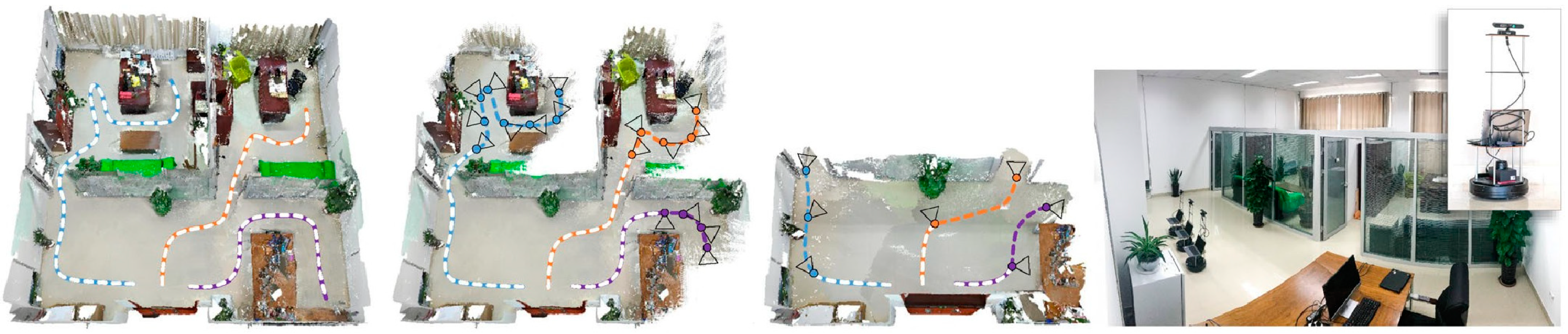
4.1. Scene Reconstruction

The reconstruction of the working scene is an integral component of the cluster’s UAV positioning and navigation technology. While measuring the object, the UAV reconstructs the scene. This is the most fundamental SLAM process, which improves its positioning accuracy by reconstructing the scene. In contrast to the target reconstruction of one or more objects in a finite volume, scene reconstruction requires a model of the entire 3D scene within the target volume. Therefore, the UAV employed to reconstruct a scene must be able to drive independently to every position within the scene. During the scanning procedure, the robot’s position must be known [143,144]. The UAV can then plan its path and sensor view based on its position and the existing local model of the scene in order to correctly scan the scene. The UAV system generates the scene reconstruction view based on criteria such as information gain, mobile cost, and reconstruction quality [141,145]. In addition to employing mobile robots on the ground for scene reconstruction [146,147,148], aerial robot platforms may also be employed [149]. Bircher et al. [149] proposed a method for view planning in MAV scene space exploration. This approach samples the view as nodes in a random tree using a tree construction algorithm such as RRT [150] or RRT-STAR [151]. NBV is computed by evaluating the unidentified information gained from each tree branch. In each iteration of view planning, the initial edge of the optimal branch is employed to scan and update the scene. MAV performs the iterative procedure in reverse until the horizon has been detected. Simulated and physical experiments were carried out simultaneously to verify that the view planner can process complex space in real-time on the MAV platform with limited computational resources.
Conventional active vision systems enhance scene knowledge by acquiring 2D scene maps [146,147] or 3D scan data [148]. By performing an offline analysis of the obtained data, the scene’s object model is reconstructed in its entirety. Xu et al. [152] proposed an online analytical method for scene reconstruction. The first of its kind, the system combines robot interaction with active verification of object extraction and scene segmentation, enabling object quality reconstruction. On the basis of this system, Xu et al. [153] reconstructed the scene by employing a 3D shape database to identify objects online, and target recognition is accomplished by a new recursive network with subnetworks for input processing, information aggregation, action generation, and next view prediction. During scene reconstruction, the reconstructed 3D objects are gradually put into the scene to replace the corresponding object scan. Liu et al. [142] proposed a comprehensive active vision system that provides target perception guidance for dynamic scene exploration and target recognition, as opposed to the method of object extraction by physical interaction. The proposed system began the navigation process by determining which object in the scene should be designated the target. The system uses multi-class graph cut minimizing for object segmentation; the target object is chosen based on the database matching degree and the robot’s traveling cost. The robot next goes to the target object and uses the information acquired from object perception to planning the NBV for local scanning. After recognizing and reconstructing the current target object, the robot continues navigation by recognizing and modeling the next target object. The robot sequentially scans and accesses all scene objects in order to reconstruct the whole scene model. Experimental results demonstrate that this strategy is more accurate and effective than the majority of related work. Based on SUNCG [154] and SCANNET [155] scene data sets, the author conducted simulation experiments. Mobile robots outfitted with Kinect sensors have additionally been employed in physical experiments. Experimental results show that the system performs well in terms of reconstruction quality and efficiency (Figure 10).
Zheng et al. [156] proposed an original online reconstruction method for active understanding of unknown indoor scenes based on semantic segmentation for similar aims. This method is applied to voxel labeling based on depth learning [157] and employs volume representation. View planning is a view scoring field that takes into account not only information gain but also security, visibility, and mobile cost. Then, the robot path and camera path are jointly optimized for the neighboring NBV. Dong et al. [141] recently proposed a multi-robot cooperative reconstruction system. Using several robots simultaneously can substantially improve the speed of scene reconstruction by minimizing the scanning effort of each robot while maximizing their aggregate coverage and quality of reconstruction. In each iteration of view planning, the algorithm decides on the optimal set of views and assigns each to a certain robot. The assignment view planning procedure can be represented by several traveling salesman problems (MTSP). This issue recognizes a path for each robot such that each task view may be accurately reached once, and the overall travel cost is minimized. Each robot is required to cross the specified view, as shown in Figure 11.
View planning employs a single depth image acquired by a depth sensor as the input for high-quality scene reconstruction [158]. The depth reinforcement learning network DQN [159] is used to determine the viewpoint sequence required to finish the occlusion space in the depth image. To compensate for any missing information, complete the assignment in an iterative manner. Each iteration would choose a new viewpoint to render a depth image, which is then internally drawn to fill the resulting empty space and re-projected into 3D space for the next iteration. The entire interior painting employs the 2D interior painting network [160] and SSCNet [154]. Continue these processes until a complete point cloud of the scene has been established. Compared to the prior scene completion methods, SSCNet [154] and ScanComplete [161], the proposed approach is more reliable and exhaustive.
Scene reconstruction and object reconstruction are quite similar from the perspective of a view planning algorithm. Both of them evaluate the view based on the amount of information it provides when selecting NBV. The chief concern in scene reconstruction is how to effectively construct a precise and comprehensive scene model. Object reconstruction requires high accuracy and requires more object details. However, scene reconstruction is more complex than object reconstruction, even though all object models in the entire region must be acquired. For viewpoint planning, the active vision system must process a great deal of information in order to realize scene reconstruction. In this process, collision and occlusion-induced uncertainty must be considered. The employment of antenna robots to analyze large areas [149], object-guided scene reconstruction combined with object recognition [142], and multi-robot cooperative reconstruction [141] have all been proposed in a recent survey and are valuable and challenging research topics.

4.2. Attitude Estimation

In the cluster of UAV positioning and navigation systems, the major focus remains the accurate estimation of its position and attitude. Attitude estimation focuses on how to accurately find components in a scene using visual data in order to interact with them further. Each observation point is deficient in information. Multi-view can provide additional information for attitude estimation. View planning is used to provide supplemental key information for matching scene objectives with database models. In order to estimate an object’s attitude, the system has to not only match the target, but also accurately recover its position and attitude. Therefore, the number of details required for attitude estimation is substantially greater than that required for target recognition. Specifically, target recognition can use features from 2D images to match without depth information, whereas attitude estimation requires depth information to accurately recover an object’s attitude. Using the view planning algorithm, the robot system typically finds the key feature points that help calculate the target attitude.
The estimation of information and the decision-making process in perspective planning is a typical Markov chain, and each perspective decision represents a state transition. Eidenberg and Scharinger [162] proposed a partially observable Markov decision process for effective target recognition and attitude estimation. The system establishes a high-dimensional Gaussian model of the object’s attitude, deduces its state transition process, and evaluates the view based on the change in entropy of the probability distribution. Wu et al. [163] simultaneously performed target recognition and attitude estimation. The robot system obtains the initial assumptions of the target and its relative orientation for the scene model during the initial stage.
Using the preprocessing method described in [164], the input RGB-D point cloud is segmented into several clusters and filtered to identify candidate clusters that may contain targets. Then, the cluster’s feature descriptors are extracted (such as SURF [165] and SIFT [166]). The corresponding relationship between clustering and database is established by feature matching and consistency matching. The system then uses the correspondence to estimate the cluster’s attitude, employing singular value decomposition (SVD) [167]. After generating the candidate view of the robot’s current posture, the view that captures the most matching feature is selected using ray-casting simulation. The process should be continued until the system can generate a reliable estimate.
Conventional machine learning techniques are critical for tackling attitude uncertainties. Doumanoglou et al. [168] proposed a new framework using active random forests [169]. This structure is used to address the challenges of classified view planning, grab point detection, and robot clothing deployment task attitude estimation. Further work by Doumanoglou et al. [170] addressed the application of Hough Forest [171] for attitude estimation planning. Hough Forest employs features automatically created by unsupervised automatic coders and then performs target classification and attitude recognition simultaneously. The new view calculates the information entropy based on the data contained in the leaf nodes of the Hough forest. NBV using the entropy reduction of the new view should then be chosen.
In the object’s attitude estimation, mutual obstruction by the target hinders observation and feature extraction. It is difficult to determine the target attitude in the scene with extreme occlusion. Sock et al. [172] established an active vision system to estimate the posture of stacked objects in highly dense and cluttered environments. The system relies initially on the most sophisticated single target attitude estimator generation hypothesis. Then, the objective hypothesis to predict the NBV is utilized. Usually, the number of visible voxels is used to calculate the information entropy, but this metric is not applicable to the 6D attitude estimation of multiple targets in a dense environment. Consequently, a viewpoint entropy considering saliency is developed, which can potentially reduce the uncertainty of attitude estimation. The system uses the potential Hoff-like forest (LHCF) [173] and sparse automatic encoder to generate the target attitude assumption of the view following image acquisition. The information acquired from each view is enhanced and processed for registration and correction. After image acquisition and registration, the system uses the accumulated point cloud and multiple 6D target assumptions to render candidate views, calculates information entropy, and chooses the candidate view with the lowest view entropy as the NBV. During pose estimation, the robot system makes numerous assumptions about the scene model, which specifies which targets are present in the scene and what attitude each target has [172]. Based on the current multi-model hypothesis, the view planner evaluates the reduced uncertainty provided by the new view and selects NBV [163,170,172]. In the pose estimation, the robot system infers the type of objects in the scene and accurately recovers their pose. Basic pose estimation involves the extraction of target features, the matching of features, and the determination of target attitude. Viewpoint planning must select an appropriate viewpoint to provide a higher quantity of feature information so that pose estimation may be completed reliably and effectively. Particularly, machine learning methods such as random forest [169] and automatic encoder [174] are beneficial for view planning in attitude estimation tasks [168,170,172].
With the advancement of UAV positioning technology and view planning methods, the application of view planning becomes increasingly applicable and demanding. It is noteworthy that more and more popular modern technologies, such as machine learning and deep neural networks, are integrated into view planning. (1) With the rapid growth of active vision, view planning tasks become more practicable. The research on this subject is not limited to laboratories, but has practical applications in many industrial scenarios, such as manufacturing, home robot services, and autonomous driving. (2) View planning algorithms will be significantly impacted by the continued development of robotics and sensors. For instance, robots can provide a broader, more flexible, and more diverse field of view. In addition to color and depth, the sensor also provides useful information regarding texture, temperature, and odor for view planning. (3) The ability of an active vision system to perform many tasks simultaneously merits consideration. Future work is increasingly inclined to construct more integrated multi-robot systems. For instance, a robot system utilized for scene exploration must commonly perform object recognition and reconstruction. Object recognition and attitude evaluation are inseparable. It is initially expected that an outstanding robot system will be able to perform multiple tasks simultaneously and that effective cooperation will bring benefits to each task. (4) In active vision view planning, the application of machine learning and deep learning technologies will be widely considered. (5) In the multi-robot system, the positioning accuracy of the multi-robot system may be effectively increased by employing active vision based on the active behavior of individual members in the UAV cluster, along with the determination of the motion model (as shown in Figure 12).
In the UAV cluster, each UAV broadcasts its own active measurement information and position in real-time while receiving information from other UAVs. Using the relative measurement between different individuals, the UAVs’ global positioning capability is enhanced. Nevertheless, considering the load limitation, the UAV sensors may be heterogeneous, and the number of UAVs in the field of vision at different times is not fixed, leading to time-varying observation quantities and the observable data problem, which makes fusion challenging. In Section 5, the key features and applications of multi-source dynamic sensing and distributed fusion technology in multi-UAV collaborative positioning are analyzed and discussed.

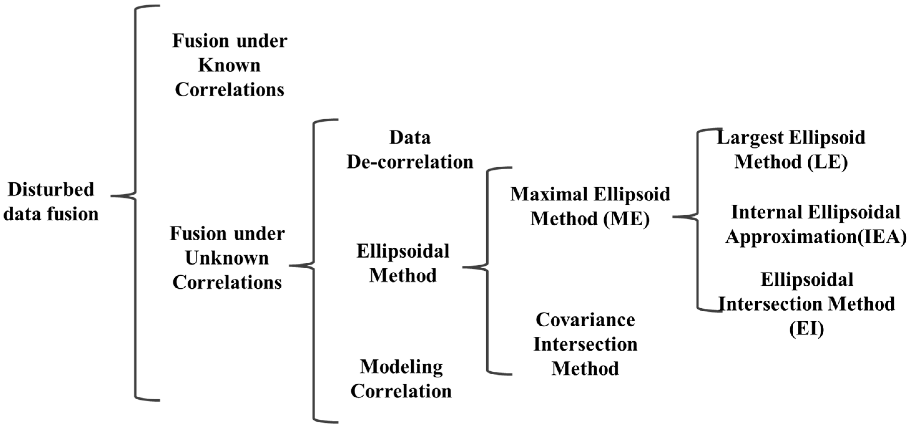
5. Distributed Fusion of Multi-Source Dynamic Sensing Information

In distributed cooperative positioning and navigation of clustered UAVs, the fusion of collected data by multiple UAVs can enhance the positioning accuracy of individual UAVs; consequently, research on multi-transmitter data fusion is critical. Multi-sensor data fusion is achieved by combining data from many sensors with model-based predictions to generate more meaningful and accurate state estimates. Currently, multi-sensor data fusion is extensively employed in process control and autonomous navigation. Although centralized fusion can produce optimal solutions in theory, it cannot scale the number of nodes; that is, as the number of nodes grows, it may or may not be feasible to handle all sensor measurements at a single terminal due to communication limits and reliability requirements. In the distributed fusion architecture [175], multi-source measurement data are independently processed at each node, and local estimates are required prior to communication to the central node for fusion. Distributed fusion, on the other hand, is robust to system failures while offering the virtue of minimal communication costs.
Nonetheless, distributed fusion must take into account the correlation between local estimates. Due to redundant calculations or the sharing of prior information or data sources, local estimates may be interdependent, but data received by distributed sensors include a clear physical relationship between their observed values [176]. In a centralized architecture where the independence hypothesis holds true, the Kalman filter (KF) [177] calculates an optimal estimate based on the minimum mean square error. In contrast, in distributed structures where the independence hypothesis does not hold, filtering without taking cross-correlation into account may result in divergence due to the mismatch between the mean and covariance of the fusion process. It remains challenging to estimate cross-correlation between data sources, particularly in a distributed fusion architecture. Fusion may be too expensive for large, distributed sensor networks, even when all cross-correlations are enabled. However, eliminating cross-correlation will result in a more conservative fusion mean and covariance.
Methods to address the unknown correlation fusion problem in distributed architecture can be categorized into three categories based on their processing techniques. (1) Data de-correlation: the input data source is de-correlated based on measurement reconstruction prior to fusion [178] or the straightforward elimination of double calculation [179,180]; (2) Modeling correlation: obtaining fusion solutions based on unknown correlation information and modeling [181,182,183,184]; (3) Ellipsoid method (EM): Under the hypothesis of bounded cross-correlation, the suboptimal but consistent fusion solution is generated by approximating the intersection of several data sources without cross-correlation information.
A second concern with sensor fusion is that sensors commonly generate unpredictable or incorrectly modeled data. Yet, the sensor may provide inconsistent and incorrect data for a variety of reasons, including sensor failure, sensor noise, and slow failure due to sensor component failure, among others [185,186,187]. The fusion of irregular sensor data with reliable data can result in extremely incorrect results [188]. Hence, inconsistencies must be identified and eliminated prior to fusing the distributed fusion architecture. Multi-sensor data fusion with inconsistencies and incorrect sensor data can be roughly categorized into three groups: (1) Model-based methods: sensor data are compared with reference to identify and eliminate inconsistencies, which can be obtained through mathematical models [189,190]; (2) Redundancy-based approaches: multiple sensors provide estimates of observed quantities, and then inconsistent estimates are identified and eliminated by consistency checking and majority voting [185]. (3) Fusion-based method: the fusion covariance is amplified to embrace all the local means and covariances, hence making the fusion estimation consistent under the pseudo-data [191,192].
Distributed sensor networks cannot match the estimated quality of centralized systems, but they are more adaptable and tolerant to faults. In distributed architectures, local sensor estimates might be linked because observations from distributed sensors may be impacted by the same process noise. Local estimations may be effective due to double counting. Cross-correlations should be considered by distributed fusion algorithms to maintain optimality and consistency.

5.1. Fusion under Known Correlations

In distributed estimating, the conditional independence of the estimation is a simplification assumption. However, neglecting cross-correlations in distributed structures might result in inconsistent outputs, which in turn can result in inconsistent outcomes in fusion methods. By combining known cross-correlations, there are several approaches for state estimation and fusion. One study [193] presented just one fusion rule that is applicable to centralized, distributed, and hybrid fusion architectures with complete prior knowledge. The authors of [194] proposed a fusion approach for discrete multi-rate independent systems based on multi-scale theory under the assumption that the sampling ratio between local estimates is a positive integer. Distributed fusion estimation of asynchronous systems with correlated noise is studied in [195,196,197].
Other researchers have also investigated learning-based multi-sensor data fusion methods [198,199,200,201,202,203]. The multi-feature fusion method proposed in the literature [200] is applied to visual recognition in multimedia applications. The authors of [201] presented a neural network-based framework for the fusion of multi-rate and multi-sensor linear systems. The framework transforms a multi-rate multi-sensor system into a single multi-sensor system with the highest sampling rate and efficiently fuses local estimates using neural networks. In [204,205], neural network-based multi-sensor data fusion was compared to the traditional method and is demonstrated to offer superior fusion performance. Nevertheless, the learning-based strategy is limited by the huge amount of training data required.
In a centralized architecture, KF/IF performs at its highest level since the independence assumption is true. By computing and combining accurate cross-correlations, it is feasible to achieve optimality in a distributed fusion architecture. In addition, the proposed fusion method can be utilized independently or cooperatively, depending on the fusion structure and practical constraints, to address the complex fusion problems.

5.2. Fusion under Unknown Correlation

There are numerous sources of correlation in a distributed architecture that affect the state estimation and fusion processes. When cross-correlation is absent, the outputs will be excessively extreme, and the fusion method could diverge. Given the double computation and lack of internal parameters, it is challenging to estimate the cross-correlation in large-scale distributed sensor networks with accuracy. Proper management and maintaining cross-correlations is complex and expensive, and the cost is quadratic with the number of updates. Thus, it appears that a suboptimal strategy is employed to seek the fusion solution based on numerous data sources without understanding the real cross-correlation. Figure 13 shows the distributed fusion classification under an unknown correlation.

5.2.1. Data De-Correlation

Cross-association of data is prevalent in distributed architectures. When the same data reaches the fusion node via a distinct or cyclic path, a double count occurs. Literature [179,180] proposes an approach for eliminating correlation by deleting duplicate counts. The purpose is to parse external measurements from other sensor nodes’ state estimates, store them, and employ them to update state estimates. In this way, double-counted data are eliminated prior to data merging. This approach presupposes a specific network structure and eliminates dependencies caused by multiple calculations. The authors of [206] propose an approach based on an algorithm derived from graph theory that is appropriate to any network topology with variable delay. Nevertheless, this is neither scalable nor practical for large sensor networks [207]. In measurement reconstruction [178], system noise is artificially modified to eliminate the correlation between measurement sequences. At fusion nodes, wireless measurements are reconstructed based on local sensor estimation. This strategy has been employed for tracking in cluttered environments [208], unordered filtering [209], and non-Gaussian distributions with the Gaussian mixture model [210]. To correctly reconstruct measurement results, however, external information such as Kalman gain, associated weight, and sensor model information must be considered [211,212]. Because de-correlation methods rely on empirical knowledge and specialized analysis of a particular real system, one‘s fusion performance is compromised. Moreover, as the number of sensors grows, these methods become incredibly inefficient and impractical.

5.2.2. Modeling Correlation

Although it is challenging to obtain accurate cross-correlations between local estimates in distributed architectures, the nature of the joint covariance matrix can impose some limitations on the cross-correlations that are feasible. In addition, certain applications can provide prior knowledge and limitations on the degree of correlation, allowing someone to infer whether estimates at the local level are strongly or weakly related. The cross-correlation is not completely unknown since the estimations provided by several sensors are neither completely independent nor completely correlated. Thus, the information regarding unknown cross-correlation can be used to enhance the accuracy of fusion solutions under uncertain correlation.
Reference [182] proposes the closed equation of scalar value fusion and the approximative solution of vector value fusion based on the uniform distribution correlation coefficient. Through the use of single covariance and constraint correlation coefficients, the compact upper bound of the joint covariance matrix from reference [213] is derived. On the basis of bounded correlation, the universal approach of bounded covariance expansion (BCINF) [214] with upper and lower cross-correlation bounds is proposed. The model proposed in [184] ensures the semi-positive value of the joint covariance matrix and complies with the canonical correlation analysis of multivariate correlation [215]. In [184], the Cholesky decomposition model of unknown cross-correlation was applied to the BC formula, and the Min-Max optimization function was employed to iteratively estimate the fusion solution to the unknown cross-correlation value. In addition, conservative fusion solutions are provided under the assumption that correlation coefficients are distributed uniformly. Using the correlation model in the BC formula, [181] analyzed the maximum limit of unknown correlation estimation from track-to-track fusion. The reference [216] studies the multi-sensor estimation issue under the norm-bounded cross-correlation hypothesis, where the worst-case fusion MSE is minimized for all feasible mutual covariances. To take advantage of some prior knowledge of mutual covariance, the tolerance formula for mutual covariance was proposed in [217] in order to capitalize on this information. Based on the proposed model, semidefinite programming (SDP) was employed to develop an optimal fusion strategy that minimizes the worst-case fusion mean square error (MSE).

5.2.3. Ellipsoidal Method

The potential cross-covariances between data sources are bound [176,218,219], thereby limiting the possible results of fusion covariances to sets with bounds. As shown in Figure 14, several mutual covariances are selected, and the covariances of fusion are located at the intersection of several data sources. The ellipsoid method (EM) aims at estimating fusion by approximating the crossing regions of several ellipsoids. Other subdivisions of EM include the covariance intersection method (CI) [219], the largest ellipsoid method (LE) [220], the inner ellipsoid approximation method (IEA) [221], and the ellipsoid intersection method (EI). The goal of the three methods, LE, IEA, and EI, is to find the maximum ellipsoid in the region where a single ellipsoid intersects, which is called the maximum ellipsoid method (ME).
Several applications involve CI approaches, including positioning [222,223,224], target tracking [225,226], simultaneous localization and mapping (SLAM) [227], image integration [228], NASA Mars Rovers [229], and spacecraft state estimation [226]. In order to avoid overestimating CI, the maximum ellipsoid approach [220] provides the greatest ellipsoid within the intersection of two independent ellipsoids. The internal ellipsoid approximation method (IEA) [221,230,231] takes into account the intersection regions of a single ellipsoid internally to complement the LE method. The ellipsoidal intersection approach [232] computes the fusion mean and covariance by employing mutually exclusive information from two data sources in order to solve the fusion problem under an unknown correlation.
In the case when the cross-correlation hypothesis is uncertain, the choice of fusion method is reliant on the prospective fusion problem. The data de-correlation method eliminates correlations prior to fusion estimation but is restricted to tiny network topologies. To achieve optimality in distributed fusion architectures, it is preferable to employ accurate cross-correlations. Thus, if there is some prior knowledge of the degree of correlation, this information may be employed to improve the estimation’s accuracy. CI methods can be used to combine data with unknown correlations in a consistent manner. However, CI results tend to be conservative and less reliable. The EI approach can produce fewer conservative solutions.

6. Open Problems and Possible Future Research Directions

Open Problem 1: Model resolution improvement and similarity model establishment based on sparse features and invariant features.
The majority of existing surface feature model approaches are typically focused on one or more of the surface features that are widely available to visible light, such as geometry, brightness, color, etc., with the lowest number of feature requirements. The research on the features of invariance is relatively limited, and the research is reasonably straightforward [233,234,235]. The information on deep features is not exploited, nor is the resolution of the surface feature model at different scales addressed. If the fast retrieval and matching of the ground object model established at a certain scale could result in mismatches and damage the geometry of the final position solution accuracy, this must be further explored and discussed. Applying feature invariance and invariance feature vector analysis, surface features and deep features are continuously extracted, and a multi-scale and highly available similarity feature model construction approach is proposed for the fundamental goal of enhancing model resolution.
Open Problem 2: Multi-scale and multi-sensor adjustment and nonlinear optimization.
As UAVs coordinate their positioning, they must share relative measurement data in real-time, resulting in an exceedingly large information vector for each UAV to address. Traditional optimization theory (such as the Kalman filter, etc.) and related optimization methods do not utilize this numerous information solution. It is essential to implement the whole network adjustment strategy, evaluate its nonlinear optimization issue, evaluate its optimization method, and learn from each other [236,237]. Analyze the optimization theory for the cooperative positioning technology of UAVs, optimize and solve the existing observation equation, and establish theoretical support for the problem of multi-scale multi-sensor position and attitude fusion estimations.
Open Problem 3: Observability of distributed cooperative measurement of UAVs.
Due to the navigation interruption or insufficient accuracy caused by factors such as single UAV sensor field of view occlusion or flight height limitation, UAV cluster distributed cooperative positioning can achieve group positioning and navigation in a large area, thereby enhancing the observability of measurements [238,239]. On the basis of considerable measurements, resolve the issue that the number of UAVs that can be observed in the field of view of a single UAV changes with time, establish a reasonable cluster hierarchical cooperative positioning method, employ the real-time broadcast inter-aircraft relative measurement information, and then improve the global positioning accuracy of UAVs through the joint calculation of the whole network adjustment and nonlinear optimization.

6.1. Research on Feature Extraction and Modeling of Key Features in Geographic Information

The existing feature extraction methods [240,241,242] have certain challenges, such as poor universality and usability in large-scale environments and low-resolution images, a lack of feature information, and complexity in modeling. First of all, study the perspective changes of images at different heights and the impact of different perspectives on the features, analyze the features of changes caused by time changes (such as seasonal changes in vegetation, shadow angles, perspective of ground objects, and the existence or absence of vehicles), and use the rich color and texture information of airborne multi-frame aerial images obtained by cameras to make use of the spectrum, space, and context. Semantic and auxiliary information are employed for the semantic description of ground objects, as well as depth information collected by deep learning, and the feature-based feature extraction approach is used to generate excellent feature extraction of ground objects in low-texture environments. After that, with a focus on sparse feature descriptors, we examined feature invariance and how much a feature depends on the local texture. In a low-texture environment, the features of each module are reconstructed separately based on the image data of the retrieved feature points.
The research on feature extraction and modeling of key features in geographic data is divided primarily into two categories: feature extraction and modeling of key features. Firstly, the edge contour of the key features is extracted from the original remote sensing image using plane expansion segmentation technology, and the geometric and attribute description of the feature contour is employed. Through describing the geometry and features, the impact of different factors can be exhaustively considered, and the necessary influence factors can be specified to constrain the contour geometry and separate the image from the figure. The ground feature identification method can be used to rapidly extract ground feature meanings based on the retrieved geometric and attribute features. Then, based on the segmented feature image and after the main feature has been extracted, the image data are divided into various components based on the feature using the connectivity of the image data and the module connection segmentation method, and the feature of each module is reconstructed using the segmentation contour extraction technology and the topological data editing function, or directly using the simple model function.

6.2. Research on Fast Matching Method of Ground Objects Based on Mapping Base Map

The existing feature matching methods [243,244,245,246,247,248] suffer from poor real-time performance, strict feature point requirements (such as a minimum number of feature points, similar lighting, scale, rotation, and viewpoint, etc.), the use of only traditional feature points, and the absence of deep feature points. The fast matching of ground objects based on a map is a similarity-based measuring challenge. We explored and analyzed the features of the geometric and semantic features of RGB images, extracted the deep feature information through the deep learning method, strengthened the feature efficiency levels, enhanced the real-time performance of retrieval and matching by reducing the number of features, and optimized the overall solution for the number of features and time loss. Given the benefits of the FAST corner point and SIFT descriptor approach, along with the position and attitude support of inertial sensors, the matching speed of ground objects is sped up, the accuracy of ground object matching is boosted, and the positioning accuracy of UAVs is enhanced.
Fast matching of ground features consists primarily of two components: fast extraction and fast matching of ground features. First, the FAST approach is employed to extract feature corners, followed by the SIFT method for giving the principal direction and descriptor for feature points. The output attitude data from various sensors is then combined with the similarity measure based on the dot product to assist the search strategy in completing the initial fast matching. Using the statistical feature point distance error method, the mismatched points are eliminated to generate the final homologous point set. According to the motion of the UAV, the camera motion between two consecutive images should be limited, with a limited range of attitude and position changes, and the update frequency of inertial data is considerably higher than that of the photograph. When comparing two subsequent image frames, the camera’s position and attitude changes can be determined by integrating the measured values of the gyroscope and AC-accelerometer. After acquiring the attitude adjustment, the feature points in the image to be matched can be re-projected, and the matching search area is demarcated based on the projection position. According to the camera attitude prediction feature point area, it can effectively minimize the amount of computation while minimizing the likelihood of mismatched points, enhancing the algorithm’s accuracy as well as speed. Following the preceding matching of features, the initial matching point set S is obtained. Unavoidably, there will be a certain number of mismatched points. Thus, it is essential to eliminate the mismatched points from the initial set of matching points. The RANSAC algorithm is a popular method to eliminate mismatched points. It estimates the model’s parameters by iterating over a collection of observational information containing “outliers.” Yet, it is an uncertain strategy that enhances the likelihood by increasing the number of rounds and requires expensive computation. Thus, we are considering just using an approach that counts the mean distance error between feature points to eliminate mismatched points.

6.3. Research on Pose Fusion Estimation Based on Multi-Sensor

In the UAV cluster, each UAV broadcasts its own measurement and position information, receives information from other UAVs in real time, and employs relative measurements between specific individuals to enhance the UAV’s global positioning capabilities. Due to the load limit, however, the UAV sensors may be heterogeneous, and the number of UAVs in the field of vision at different times is not fixed, resulting in time-varying observation and measurement, which introduces the problem of data obfuscation and complicating fusion. The conventional optimization model [249,250] is impractical for this distributed, time-varying system, but the network-wide adjustment that incorporates nonlinear optimization is extremely effective at resolving this issue. In addition, we propose feature-level fusion based on the existing theory of data fusion, taking into account the difficulty of fusing data at the data level and the high cost of preprocessing at the decision level. For the proper positioning of various sensors, fusion data are required. Selecting the nonlinear optimization adjustment method for the UAV position and attitude fusion estimation at the feature layer can help reduce the computational complexity of the data fusion and better adapt to the complex dynamic environment based on the application environment requirements and the capability of the airborne processing unit. This approach is essentially based on the theory of estimating and generates the state space model for various sensor data before estimating its state so as to do data fusion.
The purpose of multi-sensor data fusion is to estimate the position and attitude of multiple UAVs accurately. Two processes comprise multi-sensor fusion estimation: multi-sensor joint calibration and feature layer fusion. The assumption of multi-vision sensor data fusion is that multiple sensors simultaneously describe the same target. There are two main methods for calibrating sensor joints. The first step is to install the sensor in accordance with the specified relative transformation relationship; the second step is to calculate the relative transformation relationship between two sensors based on the constraint relationship between distinct sensor data. After sensor failure maintenance, the first method must be recalibrated, and the relative inaccuracy will probably continue to be due to the UAV’s movement-induced vibration. Thus, it is proposed that the second calibration approach be employed for the joint calibration of this project.
The coordinate conversion coefficient matrix equation is generated using geometric restrictions and the given calibration plate in order to calculate the conversion connection between multiple camera coordinate systems. In addition, for a monocular camera that has not been calibrated or exhibits a high calibration error, the global optimization approach can be employed to optimize the camera’s internal and external calibrations simultaneously. By analyzing the structure and characteristics of multi-sensors carried by multiple UAVs, as well as their measurement information and error distribution characteristics, a whole network adjustment method with non-linear optimization is proposed for UAV position and attitude fusion estimation at the feature level.

6.4. Research on Absolute Position Estimation Method of Multi-UAV Scale Matching Based on Ground Features

Given the differences in load and flight speed of heterogeneous UAVs during cooperative positioning of multiple UAVs, the number of UAVs that might be observed in the field of vision of UAVs at different times is unpredictable, and low-altitude UAVs suffer an obstacle avoidance challenge [20,251]. When an unmanned aerial vehicle (UAV) changes its altitude, the corresponding camera image’s perspective and imaging parameters fluctuate, which makes scale matching and recognizing multiple UAVs challenging. By analyzing the structure and characteristics of the sensors carried by multiple UAVs, the influence of perspective changes and differences on the characteristics of the images acquired by the camera at different heights, and the effect of time changes on the light intensity, the image is de-noised to improve the signal-to-noise ratio and enhance the feature information. Deep learning is a technique for extracting depth features that is insensitive to shifts in scale. However, its usefulness is quite poor, and it requires global optimization of attitude upon initial matching. The goal of image registration is to address the UAV’s unique localization challenge. With the method of deep learning, the image of the measuring platform’s common features is learned, and then the UAV’s real-time position is estimated through matching. Attitude parameter optimization is a SLAM problem. With the process of attitude optimization, the attitude of the camera or a landmark can be corrected during camera movement to enhance positioning accuracy.
Scale-matching positioning of multiple UAVs is principally comprised of UAV-satellite image registration and attitude parameter optimization. At first, when UAV images and satellite images are matched, CNN is employed to learn the common features (geometry, color, texture, etc.) between UAV images and satellite images, and then UAV images and satellite images are registered. The CNN network may be employed to learn the effective features between the calibrated satellite image and the UAV image under a variety of illumination conditions (such as seasonal changes, shifts in time, different visual angles, and the presence of moving objects) and directly align all image pixels because this can make use of the global texture of the image during image registration, which is crucial for registration of low-texture images. By aligning the UAV image with the satellite image, the UAV’s positioning information may be retrieved. Then, by employing the mutual measurement information between multiple UAVs, all pose parameters in the whole image sequence are optimized, and the attitude map optimization technology is utilized to attempt to optimize the attitude of the camera or landmark when the camera is moving. The photometric beam is employed to directly optimize the pixel intensity by optimizing the sum of the square differences between the pixel intensities of adjacent UAV frames and the sum of the square differences between the UAV frames and the satellite map. The major advantage of this method is that only a smaller frame set is required to match the satellite map, enabling the UAV to be accurately localized on all frames.

7. Conclusions

In this paper, we review and evaluate the most emerging advances and advancements in the study of multi-UAV visual cooperative positioning (including autonomous intelligent positioning and navigation of UAVs based on vision, distributed cooperative measurement and fusion in cluster high dynamic topology, group navigation based on active behavior control, and distributed fusion of multi-source dynamic perception information). While GNSS signals are denied, the UAV’s only options for position perception are limited communication and self-carrying sensors (such as inertial navigation and vision). Although inertial navigation drift is random, its uncertainties can be reduced by adjusting the network system through the cluster’s information-sharing mechanism. Long-term flight without a guiding anchor will cause the cluster positioning datum to diverge at the same time. With the use of data from earth observations, the visual positioning technologies based on geographic information were employed to extract the invariant feature information of ground objects. The entire group drift was eliminated by comparing prefabricated geographic information data and adjusting for multiple-view observations.
The visual odometry approach for earth observation is significantly expanded to account for the discontinuity and low overlap rate of observed images in the case of fast maneuvering with geographic information, thereby enhancing the cumulative measurement accuracy and robustness of visual odometry. With the rich color and texture information of the aerial multi-frame images captured by the camera, the spectral, spatial, contextual, semantic, and auxiliary information in the images, as well as the depth information extracted by deep learning, may be employed to describe the semantic features of the ground objects, enabling the effective extraction of the features of the ground objects in the low-texture environment. A real-time frame can be roughly registered with a satellite image using a multi-view geographic positioning approach to transform the perspective projection of a UAV image. A satellite image with a realistic appearance and maintained content is generated from the corresponding UAV perspective, which can bridge the obvious gap in perspective between the two domains and enable geographic positioning. In a drone cluster, each drone broadcasts measurements and positions and receives information from other drones in real time. The relative measurement between different individuals can enhance the drone’s capacity to locate itself globally and properly react to the complex and difficult dynamic environment.

Author Contributions

Conceptualization, P.T. and X.Y.; methodology, P.T. and P.W.; writing—original draft preparation, P.T.; writing—review and editing, X.Y. and Y.Y.; supervision, X.Y. and W.L. All authors have read and agreed to the published version of the manuscript.

Funding

This research received no external funding.

Institutional Review Board Statement

Not applicable.

Informed Consent Statement

Not applicable.

Data Availability Statement

Not applicable.

Conflicts of Interest

The authors declare no conflict of interest.

References

  1. Radočaj, D.; Šiljeg, A.; Plaščak, I.; Marić, I.; Jurišić, M. A Micro-Scale Approach for Cropland Suitability Assessment of Permanent Crops Using Machine Learning and a Low-Cost UAV. Agronomy 2023, 13, 362. [Google Scholar] [CrossRef]
  2. Mohsan, S.A.H.; Othman, N.Q.H.; Khan, M.A.; Amjad, H.; Żywiołek, J. A comprehensive review of micro UAV charging techniques. Micromachines 2022, 13, 977. [Google Scholar] [CrossRef]
  3. Liu, X.; Li, H.; Yang, S. Optimization Method of High-Precision Control Device for Photoelectric Detection of Unmanned Aerial Vehicle Based on POS Data. Sci. Program. 2022, 2022, 2449504. [Google Scholar] [CrossRef]
  4. Wang, Y.; Chen, H.; Liu, Q.; Huang, J. Key Technologies of the Cooperative Combat of Manned Aerial Vehicle and Unmanned Aerial Vehicle. In Advances in Guidance, Navigation and Control: Proceedings of 2022 International Conference on Guidance, Navigation and Control, Harbin, China, 5–7 August 2022; Springer Nature Singapore: Singapore, 2023; pp. 671–679. [Google Scholar]
  5. Lu, Y.; Qin, W.; Zhou, C.; Liu, Z. Automated detection of dangerous work zone for crawler crane guided by UAV images via Swin Transformer. Autom. Constr. 2023, 147, 104744. [Google Scholar] [CrossRef]
  6. Rehan, M.; Akram, F.; Shahzad, A.; Shams, T.A.; Ali, Q. Vertical take-off and landing hybrid unmanned aerial vehicles: An overview. Aeronaut. J. 2022, 126, 1–41. [Google Scholar] [CrossRef]
  7. Çoban, S. Autonomous performance maximization of research-based hybrid unmanned aerial vehicle. Aircr. Eng. Aerosp. Technol. 2020, 92, 645–651. [Google Scholar] [CrossRef]
  8. Alqurashi, F.A.; Alsolami, F.; Abdel-Khalek, S.; Sayed Ali, E.; Saeed, R.A. Machine learning techniques in internet of UAVs for smart cities applications. J. Intell. Fuzzy Syst. 2022, 42, 3203–3226. [Google Scholar] [CrossRef]
  9. Amarasingam, N.; Salgadoe, S.; Powell, K.; Gonzalez, L.F.; Natarajan, S. A review of UAV platforms, sensors, and applications for monitoring of sugarcane crops. Remote Sens. Appl. Soc. Environ. 2022, 26, 100712. [Google Scholar] [CrossRef]
  10. Li, B.; Liu, B.; Han, D.; Wang, Z. Autonomous Tracking of ShenZhou Reentry Capsules Based on Heterogeneous UAV Swarms. Drones 2023, 7, 20. [Google Scholar] [CrossRef]
  11. Akter, R.; Golam, M.; Doan, V.S.; Lee, J.M.; Kim, D.S. Iomt-net: Blockchain integrated unauthorized uav localization using lightweight convolution neural network for internet of military things. IEEE Internet Things J. 2022, 10, 6634–6651. [Google Scholar] [CrossRef]
  12. AL-Dosari, K.; Hunaiti, Z.; Balachandran, W. Systematic Review on Civilian Drones in Safety and Security Applications. Drones 2023, 7, 210. [Google Scholar] [CrossRef]
  13. Maddikunta, P.K.R.; Hakak, S.; Alazab, M.; Bhattacharya, S.; Gadekallu, T.R.; Khan, W.Z.; Pham, Q.V. Unmanned aerial vehicles in smart agriculture: Applications, requirements, and challenges. IEEE Sens. J. 2021, 21, 17608–17619. [Google Scholar] [CrossRef]
  14. Sal, F. Simultaneous swept anhedral helicopter blade tip shape and control-system design. Aircr. Eng. Aerosp. Technol. 2023, 95, 101–112. [Google Scholar] [CrossRef]
  15. Khan, A.; Zhang, J.; Ahmad, S.; Memon, S.; Qureshi, H.A.; Ishfaq, M. Dynamic positioning and energy-efficient path planning for disaster scenarios in 5G-assisted multi-UAV environments. Electronics 2022, 11, 2197. [Google Scholar] [CrossRef]
  16. Gyagenda, N.; Hatilima, J.V.; Roth, H.; Zhmud, V. A review of GNSS-independent UAV navigation techniques. Robot. Auton. Syst. 2022, 152, 104069. [Google Scholar] [CrossRef]
  17. Gao, W.; Yue, F.; Xia, Z.; Liu, X.; Zhang, C.; Liu, Z.; Jin, S.; Zhang, Y.; Zhao, Z.; Zhang, T.; et al. Weak Signal Processing Method for Moving Target of GNSS-S Radar Based on Amplitude and Phase Self-Correction. Remote Sens. 2023, 15, 969. [Google Scholar] [CrossRef]
  18. Gao, W.; Xu, Z.; Han, X.; Pan, C. Recent advances in curved image sensor arrays for bioinspired vision system. Nano Today 2022, 42, 101366. [Google Scholar] [CrossRef]
  19. Liu, Z.; Cao, Y.; Gao, P.; Hua, X.; Zhang, D.; Jiang, T. Multi-UAV network assisted intelligent edge computing: Challenges and opportunities. China Commun. 2022, 19, 258–278. [Google Scholar] [CrossRef]
  20. Tang, J.; Duan, H.; Lao, S. Swarm intelligence algorithms for multiple unmanned aerial vehicles collaboration: A comprehensive review. Artif. Intell. Rev. 2022, 1–33. [Google Scholar] [CrossRef]
  21. Shen, S.; Mulgaonkar, Y.; Michael, N.; Kumar, V. Multi-sensor fusion for robust autonomous flight in indoor and outdoor environments with a rotorcraft MAV. In Proceedings of the 2014 IEEE International Conference on Robotics and Automation (ICRA), Hong Kong, China, 31 May–7 June 2014; pp. 4974–4981. [Google Scholar]
  22. Mueller, M.W.; Hamer, M.; D’Andrea, R. Fusing ultra-wideband range measurements with accelerometers and rate gyroscopes for quadrocopter state estimation. In Proceedings of the 2015 IEEE International Conference on Robotics and Automation (ICRA), Seattle, WA, USA, 26–30 May 2015; pp. 1730–1736. [Google Scholar]
  23. Engel, J.; Sturm, J.; Cremers, D. Camera-based navigation of a low-cost quadrocopter. In Proceedings of the 2012 IEEE/RSJ International Conference on Intelligent Robots and Systems, Vilamoura-Algarve, Portugal, 7–12 October 2012; pp. 2815–2821. [Google Scholar]
  24. Nemra, A.; Aouf, N. Robust cooperative UAV visual SLAM. In Proceedings of the 2010 IEEE 9th International Conference on Cyberntic Intelligent Systems, Reading, UK, 1–2 September 2010; pp. 1–6. [Google Scholar]
  25. Loianno, G.; Thomas, J.; Kumar, V. Cooperative localization and mapping of MAVs using RGB-D sensors. In Proceedings of the 2015 IEEE International Conference on Robotics and Automation (ICRA), Seattle, WA, USA, 26–30 May 2015; pp. 4021–4028. [Google Scholar]
  26. Piasco, N.; Marzat, J.; Sanfourche, M. Collaborative localization and formation flying using distributed stereo-vision. In Proceedings of the 2016 IEEE International Conference on Robotics and Automation (ICRA), Stockholm, Sweden, 16–21 May 2016; pp. 1202–1207. [Google Scholar]
  27. Fei, W.; Jin-Qiang, C.U.I.; Ben-Mei, C.H.E.N.; Tong, H.L. A comprehensive UAV indoor navigation system based on vision optical flow and laser FastSLAM. Acta Autom. Sin. 2013, 39, 1889–1899. [Google Scholar]
  28. Bryson, M.; Sukkarieh, S. Building a Robust Implementation of Bearing-only Inertial SLAM for a UAV. J. Field Robot. 2007, 24, 113–143. [Google Scholar] [CrossRef] [Green Version]
  29. Kim, J.; Sukkarieh, S. Real-time implementation of airborne inertial-SLAM. Robot. Auton. Syst. 2007, 55, 62–71. [Google Scholar] [CrossRef]
  30. Gandhi, D.; Pinto, L.; Gupta, A. Learning to fly by crashing. In Proceedings of the 2017 IEEE/RSJ International Conference on Intelligent Robots and Systems (IROS), Vancouver, BC, Canada, 24–28 September 2017; pp. 3948–3955. [Google Scholar]
  31. Pinto, L.; Gupta, A. Supersizing self-supervision: Learning to grasp from 50k tries and 700 robot hours. In Proceedings of the 2016 IEEE International Conference on Robotics and Automation (ICRA), Stockholm, Sweden, 16–21 May 2016; pp. 3406–3413. [Google Scholar]
  32. Fu, Q.; Quan, Q.; Cai, K.-Y. Robust pose estimation for multirotor UAVs using off-board monocular vision. IEEE Trans. Ind. Electron. 2017, 64, 7942–7951. [Google Scholar] [CrossRef]
  33. Zhou, H.; Zou, D.; Pei, L.; Ying, R.; Liu, P.; Yu, W. StructSLAM: Visual SLAM with building structure lines. IEEE Trans. Veh. Technol. 2015, 64, 1364–1375. [Google Scholar] [CrossRef]
  34. Zou, D.; Tan, P. Coslam: Collaborative visual slam in dynamic environments. IEEE Trans. Pattern Anal. Mach. Intell. 2012, 35, 354–366. [Google Scholar] [CrossRef]
  35. Wang, K.; Shen, S. Mvdepthnet: Real-time multiview depth estimation neural network. In Proceedings of the 2018 International Conference on 3d Vision (3DV), Verona, Italy, 5–8 September 2018; pp. 248–257. [Google Scholar]
  36. Leutenegger, S.; Lynen, S.; Bosse, M.; Siegwart, R.; Furgale, P. Keyframe-based visual–inertial odometry using nonlinear optimization. Int. J. Robot. Res. 2015, 34, 314–334. [Google Scholar] [CrossRef] [Green Version]
  37. Li, M.; Mourikis, A.I. High-precision, consistent EKF-based visual–inertial odometry. Int. J. Robot. Res. 2013, 32, 690–711. [Google Scholar] [CrossRef]
  38. Bloesch, M.; Omari, S.; Hutter, M.; Siegwart, R. Robust visual inertial odometry using a direct EKF-based approach. In Proceedings of the 2015 IEEE/RSJ International Conference on Intelligent Robots and Systems (IROS), Hamburg, Germany, 28 September–2 October 2015; pp. 298–304. [Google Scholar]
  39. Leprince, S.; Barbot, S.; Ayoub, F.; Avouac, J.P. Automatic and precise orthorectification, coregistration, and subpixel correlation of satellite images, application to ground deformation measurements. IEEE Trans. Geosci. Remote Sens. 2007, 45, 1529–1558. [Google Scholar] [CrossRef] [Green Version]
  40. Google Earth, Google. 2022. Available online: https://www.google.com/earth/ (accessed on 15 July 2022).
  41. ArcGIS Online, Esri. 2022. Available online: https://www.arcgis.com/index.html (accessed on 10 June 2022).
  42. Couturier, A.; Akhloufi, M.A. Relative visual localization (RVL) for UAV navigation. In Degraded Environments: Sensing, Processing, and Display 2018; SPIE: Bellingham, WA, USA, 2018; Volume 10642, pp. 213–226. [Google Scholar]
  43. Couturier, A.; Akhloufi, M.A. UAV navigation in GPS-denied environment using particle filtered RVL. In Situation Awareness in Degraded Environments 2019; SPIE: Bellingham, WA, USA, 2019; Volume 11019, pp. 188–198. [Google Scholar]
  44. Couturier, A.; Akhloufi, M. Conditional probabilistic relative visual localization for unmanned aerial vehicles. In Proceedings of the 2020 IEEE Canadian Conference on Electrical and Computer Engineering (CCECE), London, ON, Canada, 30 August–2 September 2020; pp. 1–4. [Google Scholar]
  45. Warren, M.; Greeff, M.; Patel, B.; Collier, J.; Schoellig, A.P.; Barfoot, T.D. There’s no place like home: Visual teach and repeat for emergency return of multirotor uavs during gps failure. IEEE Robot. Autom. Lett. 2018, 4, 161–168. [Google Scholar] [CrossRef] [Green Version]
  46. Brunelli, R. Template Matching Techniques in Computer Vision: Theory and Practice; John Wiley & Sons: Hoboken, NJ, USA, 2009. [Google Scholar]
  47. Brunelli, R.; Poggiot, T. Template matching: Matched spatial filters and beyond. Pattern Recognit. 1997, 30, 751–768. [Google Scholar] [CrossRef] [Green Version]
  48. Van Dalen, G.J.; Magree, D.P.; Johnson, E.N. Absolute localization using image alignment and particle filtering. In Proceedings of the AIAA Guidance, Navigation, and Control Conference, San Diego, CA, USA, 4–8 January 2016; p. 647. [Google Scholar]
  49. Lewis, J.P. Fast template matching. Vis. Interface. 1995, 95, 15–19. [Google Scholar]
  50. Thrun, S. Particle Filters in Robotics. UAI 2002, 2, 511–518. [Google Scholar]
  51. Bing Maps, Microsoft. 2022. Available online: https://www.bing.com/maps (accessed on 17 December 2022).
  52. Magree, D.P.; Johnson, E.N. A monocular vision-aided inertial navigation system with improved numerical stability. In Proceedings of the AIAA Guidance, Navigation, and Control Conference, Kissimmee, FL, USA, 5–9 January 2015; p. 97. [Google Scholar]
  53. Sasiadek, J.; Wang, Q.; Johnson, R.; Sun, L.; Zalewski, J. UAV navigation based on parallel extended Kalman filter. In Proceedings of the AIAA Guidance, Navigation, and Control Conference and Exhibit, Dever, CO, USA, 14–17 August 2000; p. 4165. [Google Scholar]
  54. Johnson, E.; Schrage, D. The Georgia Tech unmanned aerial research vehicle: GTMax. In Proceedings of the AIAA Guidance, Navigation, and Control Conference and Exhibit, Austin, TX, USA, 11–14 August 2003; p. 5741. [Google Scholar]
  55. Yol, A.; Delabarre, B.; Dame, A.; Dartois, J.É.; Marchand, E. Vision-based absolute localization for unmanned aerial vehicles. In Proceedings of the 2014 IEEE/RSJ International Conference on Intelligent Robots and Systems, Chicago, IL, USA, 14–18 September 2014; pp. 3429–3434. [Google Scholar]
  56. Cover, T.M. Elements of Information Theory; John Wiley & Sons: Hoboken, NJ, USA, 1999. [Google Scholar]
  57. Gray, R.M. Entropy and Information Theory; Springer Science & Business Media: Berlin, Germany, 2011. [Google Scholar]
  58. Wan, X.; Liu, J.; Yan, H.; Morgan, G.L. Illumination-invariant image matching for autonomous UAV localisation based on optical sensing. ISPRS J. Photogramm. Remote Sens. 2016, 119, 198–213. [Google Scholar] [CrossRef]
  59. Keller, Y.; Averbuch, A. A projection-based extension to phase correlation image alignment. Signal Process. 2007, 87, 124–133. [Google Scholar] [CrossRef]
  60. Patel, B. Visual Localization for UAVs in Outdoor GPS-Denied Environments; University of Toronto (Canada): Toronto, ON, Canada, 2019. [Google Scholar]
  61. Pascoe, G.; Maddern, W.P.; Newman, P. Robust direct visual localization using normalised information distance. In Proceedings of the British Machine Vision Conference, Oxford, UK, 21–24 November 2015; pp. 70–71. [Google Scholar]
  62. Harris, C.; Stephens, M. A combined corner and edge detector. In Proceedings of the Alvey Vision Conference 1988, Manchester, UK, 1 January 1988; Volume 15, pp. 10–5244. [Google Scholar]
  63. Rosten, E.; Drummond, T. Machine learning for high-speed corner detection. In Computer Vision—ECCV 2006; Lecture Notes in Computer Science; Leonardis, A., Bischof, H., Pinz, A., Eds.; Springer: Berlin/Heidelberg, Germany, 2006; pp. 430–443. [Google Scholar]
  64. Rosten, E.; Porter, R.; Drummond, T. Faster and better: A machine learning approach to corner detection. IEEE Trans. Pattern Anal. Mach. Intell. 2010, 32, 105–119. [Google Scholar] [CrossRef] [PubMed] [Green Version]
  65. Tang, G.; Liu, Z.; Xiong, J. Distinctive image features from illumination and scale invariant keypoints. Multimed. Tools Appl. 2019, 78, 23415–23442. [Google Scholar] [CrossRef]
  66. Calonder, M.; Lepetit, V.; Strecha, C.; Fua, P. BRIEF: Binary robust independent elementary features. In Computer Vision—ECCV 2010; Lecture Notes in Computer Science; Daniilidis, K., Maragos, P., Paragios, N., Eds.; Springer: Berlin/Heidelberg, Germany, 2010; pp. 778–792. [Google Scholar]
  67. Seema, B.S.; Hemanth, K.; Naidu, V.P.S. Geo-registration of aerial images using RANSAC algorithm. In NCTAESD-2014; Vemana Institute of Technology: Bangalore, India, 2014; pp. 1–5. [Google Scholar]
  68. Saranya, K.C.; Naidu, V.P.S.; Singhal, V.; Tanuja, B.M. Application of vision based techniques for UAV position estimation. In Proceedings of the 2016 International Conference on Research Advances in Integrated Navigation Systems (RAINS), Bangalore, India, 6–7 May 2016; pp. 1–5. [Google Scholar]
  69. Fischler, M.A.; Bolles, R.C. Random sample consensus: A paradigm for model fitting with applications to image analysis and automated cartography. Commun. ACM 1981, 24, 381–395. [Google Scholar] [CrossRef]
  70. Bay, H.; Tuytelaars, T.; Van Gool, L. SURF: Speeded up robust features. In Computer Vision—ECCV 2006; Lecture Notes in Computer Science; Leonardis, A., Bischof, H., Pinz, A., Eds.; Springer: Berlin/Heidelberg, Germany, 2006; pp. 404–417. [Google Scholar]
  71. Shan, M.; Wang, F.; Lin, F.; Gao, Z.; Tang, Y.Z.; Chen, B.M. Google map aided visual navigation for UAVs in GPS-denied environment. In Proceedings of the 2015 IEEE International Conference on Robotics and Biomimetics (ROBIO), Zhuhai, China, 6–9 December 2015; pp. 114–119. [Google Scholar]
  72. Dalal, N.; Triggs, B. Histograms of oriented gradients for human detection. In Proceedings of the 2005 IEEE Computer Society Conference on Computer Vision and Pattern Recognition (CVPR’05), San Diego, CA, USA, 25 July 2005; Volume 1, pp. 886–893. [Google Scholar]
  73. Horn, B.K.P.; Schunck, B.G. Determining optical flow. Artif. Intell. 1981, 17, 185–203. [Google Scholar] [CrossRef] [Green Version]
  74. Bolme, D.S.; Beveridge, J.R.; Draper, B.A.; Lui, Y.M. Visual object tracking using adaptive correlation filters. In Proceedings of the 2010 IEEE Computer Society Conference on Computer Vision and Pattern Recognition, San Francisco, CA, USA, 13–18 June 2010; pp. 2544–2550. [Google Scholar]
  75. Chiu, H.P.; Das, A.; Miller, P.; Samarasekera, S.; Kumar, R. Precise vision-aided aerial navigation. In Proceedings of the 2014 IEEE/RSJ International Conference on Intelligent Robots and Systems, Chicago, IL, USA, 14–18 September 2014; pp. 688–695. [Google Scholar]
  76. Mantelli, M.; Pittol, D.; Neuland, R.; Ribacki, A.; Maffei, R.; Jorge, V.; Prestes, E.; Kolberg, M. A novel measurement model based on abBRIEF for global localization of a UAV over satellite images. Robot. Auton. Syst. 2019, 112, 304–319. [Google Scholar] [CrossRef]
  77. Masselli, A.; Hanten, R.; Zell, A. Localization of unmanned aerial vehicles using terrain classification from aerial images. In Advances in Intelligent Systems and Computing; Intelligent Autonomous Systems 13; Springer International Publishing: Berlin/Heidelberg, Germany, 2016; pp. 831–842. [Google Scholar] [CrossRef]
  78. Rublee, E.; Rabaud, V.; Konolige, K.; Bradski, G. ORB: An efficient alternative to SIFT or SURF. In Proceedings of the 2011 International Conference on Computer Vision, Barcelona, Spain, 6–13 November 2011; pp. 2564–2571. [Google Scholar]
  79. Cutler, A.; Cutler, D.R.; Stevens, J.R. Random forests. In Ensemble Machine Learning: Methods and Applications; Springer: New York, NY, USA, 2012; pp. 157–175. [Google Scholar]
  80. Shan, M.; Charan, A. Google map referenced UAV navigation via simultaneous feature detection and description. In Proceedings of the IEEE/RSJ International Conference on Intelligent Robots and Systems (IROS), Hamburg, Germany, 28 September–2 October 2015. [Google Scholar]
  81. Tombari, F.; Di Stefano, L. Interest points via maximal self-dissimilarities. In Computer Vision—ACCV 2014; Lecture Notes in Computer Science; Cremers, D., Reid, I., Saito, H., Yang, M.-H., Eds.; Springer International Publishing: Singapore, 2014; pp. 586–600. [Google Scholar]
  82. Shechtman, E.; Irani, M. Matching local self-similarities across images and videos. In Proceedings of the 2007 IEEE Conference on Computer Vision and Pattern Recognition, Minneapolis, MN, USA, 17–22 June 2007; pp. 1–8. [Google Scholar]
  83. Chen, X.; Luo, X.; Weng, J.; Luo, W.; Li, H.; Tian, Q. Multi-view gait image generation for cross-view gait recognition. IEEE Trans. Image Process. 2021, 30, 3041–3055. [Google Scholar] [CrossRef]
  84. Yan, X.; Lou, Z.; Hu, S.; Ye, Y. Multi-task information bottleneck co-clustering for unsupervised cross-view human action categorization. ACM Trans. Knowl. Discov. Data (TKDD) 2020, 14, 1–23. [Google Scholar] [CrossRef] [Green Version]
  85. Liu, X.; Liu, W.; Zheng, J.; Yan, C.; Mei, T. Beyond the parts: Learning multi-view cross-part correlation for vehicle re-identification. In Proceedings of the 28th ACM International Conference on Multimedia, Seattle, WA, USA, 12–16 October 2020. [Google Scholar]
  86. Zhao, J.; Han, R.; Gan, Y.; Wan, L.; Feng, W.; Wang, S. Human identification and interaction detection in cross-view multi-person videos with wearable cameras. In Proceedings of the 28th ACM International Conference on Multimedia, Seattle, WA, USA, 12–16 October 2020. [Google Scholar]
  87. Shao, Z.; Li, Y.; Zhang, H. Learning representations from skeletal self-similarities for cross-view action recognition. IEEE Trans. Circuits Syst. Video Technol. 2020, 31, 160–174. [Google Scholar] [CrossRef]
  88. Xu, C.; Makihara, Y.; Li, X.; Yagi, Y.; Lu, J. Cross-view gait recognition using pairwise spatial transformer networks. IEEE Trans. Circuits Syst. Video Technol. 2020, 31, 260–274. [Google Scholar] [CrossRef]
  89. Cai, S.; Guo, Y.; Khan, S.; Hu, J.; Wen, G. Ground-to-aerial image geo-localization with a hard exemplar reweighting triplet loss. In Proceedings of the IEEE/CVF International Conference on Computer Vision, Seoul, Republic of Korea, 27 October–2 November 2019. [Google Scholar]
  90. Shi, Y.; Yu, X.; Liu, L.; Zhang, T.; Li, H. Optimal feature transport for cross-view image geo-localization. In Proceedings of the AAAI Conference on Artificial Intelligence, New York, NY, USA, 7–12 February 2020. [Google Scholar]
  91. Regmi, K.; Borji, A. Cross-view image synthesis using geometry-guided conditional gans. Comput. Vis. Image Underst. 2019, 187, 102788. [Google Scholar] [CrossRef] [Green Version]
  92. Regmi, K.; Shah, M. Bridging the domain gap for ground-to-aerial image matching. In Proceedings of the IEEE/CVF International Conference on Computer Vision, Seoul, Republic of Korea, 27 October–2 November 2019. [Google Scholar]
  93. Shi, Y.; Liu, L.; Yu, X.; Li, H. Spatial-aware feature aggregation for image based cross-view geo-localization. In Proceedings of the Advances in Neural Information Processing Systems, Vancouver, BC, Canada, 8–14 February 2019; p. 32. [Google Scholar]
  94. Shi, Y.; Yu, X.; Campbell, D.; Li, H. Where am I looking at? joint location and orientation estimation by cross-view matching. In Proceedings of the IEEE/CVF Conference on Computer Vision and Pattern Recognition, Seattle, WA, USA, 16–20 June 2020. [Google Scholar]
  95. Toker, A.; Zhou, Q.; Maximov, M.; Leal-Taixé, L. Coming down to earth: Satellite-to-street view synthesis for geo-localization. In Proceedings of the IEEE/CVF Conference on Computer Vision and Pattern Recognition, Kuala Lumpur, Malaysia, 18–20 December 2021. [Google Scholar]
  96. Zheng, Z.; Wei, Y.; Yang, Y. University-1652: A multi-view multi-source benchmark for drone-based geo-localization. In Proceedings of the 28th ACM International Conference on Multimedia, Seattle, WA, USA, 12–16 October 2020. [Google Scholar]
  97. Wang, T.; Zheng, Z.; Yan, C.; Zhang, J.; Sun, Y.; Zheng, B.; Yang, Y. Each part matters: Local patterns facilitate cross-view geo-localization. IEEE Trans. Circuits Syst. Video Technol. 2021, 32, 867–879. [Google Scholar] [CrossRef]
  98. Ding, L.; Zhou, J.; Meng, L.; Long, Z. A practical cross-view image matching method between UAV and satellite for UAV-based geo-localization. Remote Sens. 2020, 13, 47. [Google Scholar] [CrossRef]
  99. Tian, X.; Shao, J.; Ouyang, D.; Shen, H.T. UAV-Satellite View Synthesis for Cross-View Geo-Localization. IEEE Trans. Circuits Syst. Video Technol. 2022, 32, 4804–4815. [Google Scholar] [CrossRef]
  100. Lin, T.Y.; Cui, Y.; Belongie, S.; Hays, J. Learning deep representations for ground-to-aerial geolocalization. In Proceedings of the IEEE Conference on Computer Vision and Pattern Recognition, Boston, MA, USA, 7–12 June 2015. [Google Scholar]
  101. Tian, Y.; Chen, C.; Shah, M. Cross-view image matching for geo-localization in urban environments. In Proceedings of the IEEE Conference on Computer Vision and Pattern Recognition, Honolulu, HI, USA, 21–26 July 2017. [Google Scholar]
  102. Liu, L.; Li, H. Lending orientation to neural networks for cross-view geo-localization. In Proceedings of the IEEE/CVF Conference on Computer Vision and Pattern Recognition, Long Beach, CA, USA, 16–20 June 2019. [Google Scholar]
  103. Workman, S.; Souvenir, R.; Jacobs, N. Wide-area image geolocalization with aerial reference imagery. In Proceedings of the IEEE International Conference on Computer Vision, Santiago, Chile, 7–13 December 2015. [Google Scholar]
  104. Workman, S.; Jacobs, N. On the location dependence of convolutional neural network features. In Proceedings of the IEEE Conference on Computer Vision and Pattern Recognition Workshops, Boston, MA, USA, 7–12 June 2015. [Google Scholar]
  105. Chen, C.; Qin, C.; Qiu, H.; Ouyang, C.; Wang, S.; Chen, L.; Tarroni, G.; Bai, W.; Rueckert, D. Realistic adversarial data augmentation for MR image segmentation. In Medical Image Computing and Computer Assisted Intervention—MICCAI 2020; Springer: Berlin, Germany, 2020. [Google Scholar]
  106. Zhang, H.; Xu, T.; Li, H.; Zhang, S.; Wang, X.; Huang, X.; Metaxas, D. Stackgan: Text to photo-realistic image synthesis with stacked generative adversarial networks. In Proceedings of the IEEE International Conference on Computer Vision, Venice, Italy, 22–29 October 2017. [Google Scholar]
  107. Lu, X.; Li, Z.; Cui, Z.; Oswald, M.R.; Pollefeys, M.; Qin, R. Geometry-aware satellite-to-ground image synthesis for urban areas. In Proceedings of the IEEE/CVF Conference on Computer Vision and Pattern Recognition, Seattle, WA, USA, 14–19 June 2020. [Google Scholar]
  108. Forster, C.; Pizzoli, M.; Scaramuzza, D. SVO: Fast semi-direct monocular visual odometry. In Proceedings of the 2014 IEEE International Conference on Robotics and Automation (ICRA), Hong Kong, China, 31 May–7 June 2014; pp. 15–22. [Google Scholar]
  109. Nister, D.; Naroditsky, O.; Bergen, J. Visual odometry. In Proceedings of the 2004 IEEE Computer Society Conference on Computer Vision and Pattern Recognition, 2004. CVPR 2004, Washington, DC, USA, 27 June–2 July 2004; Volume 1. [Google Scholar]
  110. Goforth, H.; Lucey, S. GPS-denied UAV localization using pre-existing satellite imagery. In Proceedings of the 2019 International Conference on Robotics and Automation (ICRA), Montreal, QC, Canada, 20–24 May 2019; pp. 2974–2980. [Google Scholar]
  111. Torr, P.H.S.; Zisserman, A. MLESAC: A new robust estimator with application to estimating image geometry. Comput. Vis. Image Underst. 2000, 78, 138–156. [Google Scholar] [CrossRef] [Green Version]
  112. Anderson, S.; Barfoot, T.D. Full STEAM ahead: Exactly sparse gaussian process regression for batch continuous-time trajectory estimation on SE(3). In Proceedings of the 2015 IEEE/RSJ International Conference on Intelligent Robots and Systems (IROS), Hamburg, Germany, 28 September–2 October 2015; pp. 157–164. [Google Scholar]
  113. Olfati-Saber, R. Kalman-consensus filter: Optimality, stability, and performance. In Proceedings of the 48h IEEE Conference on Decision and Control (CDC) held jointly with 2009 28th Chinese Control Conference, Shanghai, China, 15–18 December 2009. [Google Scholar]
  114. Yu, L.; You, H.; Haipeng, W. Squared-root cubature information consensus filter for non-linear decentralised state estimation in sensor networks. IET Radar Sonar Navig. 2014, 8, 931–938. [Google Scholar] [CrossRef]
  115. De Souza, C.E.; Kinnaert, M.; Coutinho, D. Consensus-based distributed mean square state estimation. In Proceedings of the 2015 American Control Conference (ACC), Chicago, IL, USA, 1–3 July 2015. [Google Scholar]
  116. Tamjidi, A.; Chakravorty, S.; Shell, D. Unifying consensus and covariance intersection for decentralized state estimation. In Proceedings of the 2016 IEEE/RSJ International Conference on Intelligent Robots and Systems (IROS), Daejeon, Republic of Republic of Korea, 9–14 October 2016. [Google Scholar]
  117. Li, W.; Wei, G.; Han, F.; Liu, Y. Weighted average consensus-based unscented Kalman filtering. IEEE Trans. Cybern. 2015, 46, 558–567. [Google Scholar] [CrossRef]
  118. Shen, K.; Jing, Z.; Dong, P. A consensus nonlinear filter with measurement uncertainty in distributed sensor networks. IEEE Signal Process. Lett. 2017, 24, 1631–1635. [Google Scholar] [CrossRef]
  119. Soatti, G.; Nicoli, M.; Savazzi, S.; Spagnolini, U. Consensus-based algorithms for distributed network-state estimation and localization. IEEE Trans. Signal Inf. Process. Over Netw. 2016, 3, 430–444. [Google Scholar] [CrossRef]
  120. Gao, C.; Wang, Z.; Hu, J.; Liu, Y.; He, X. Consensus-Based Distributed State Estimation Over Sensor Networks with Encoding-Decoding Scheme: Accommodating Bandwidth Constraints. IEEE Trans. Netw. Sci. Eng. 2022, 9, 4051–4064. [Google Scholar] [CrossRef]
  121. Liu, Y.; Liu, J.; Xu, C.; Wang, C.; Qi, L.; Ding, Z. Distributed consensus state estimation algorithm in asymmetric networks. Syst. Eng. Electron. 2018, 40, 1917–1925. [Google Scholar]
  122. Zhou, F.; Wang, Y.; Zheng, W.; Li, Z.; Wen, X. Fast Distributed Multiple-Model Nonlinearity Estimation for Tracking the Non-Cooperative Highly Maneuvering Target. Remote Sens. 2022, 14, 4239. [Google Scholar] [CrossRef]
  123. Cicala, M.; D’Amato, E.; Notaro, I.; Mattei, M. Scalable distributed state estimation in UTM context. Sensors 2020, 20, 2682. [Google Scholar] [CrossRef]
  124. He, S.; Shin, H.-S.; Xu, S.; Tsourdos, A. Distributed estimation over a low-cost sensor network: A review of state-of-the-art. Inf. Fusion 2020, 54, 21–43. [Google Scholar] [CrossRef]
  125. Chen, S.; Li, Y.; Kwok, N.M. Active vision in robotic systems: A survey of recent developments. Int. J. Robot. Res. 2011, 30, 1343–1377. [Google Scholar] [CrossRef]
  126. Scott, W.R.; Roth, G.; Rivest, J.-F. View planning for automated three-dimensional object reconstruction and inspection. ACM Comput. Surv. (CSUR) 2003, 35, 64–96. [Google Scholar] [CrossRef]
  127. Roy, S.D.; Chaudhury, S.; Banerjee, S. Active recognition through next view planning: A survey. Pattern Recognit. 2004, 37, 429–446. [Google Scholar]
  128. Scott, W.R. Model-based view planning. Mach. Vis. Appl. 2009, 20, 47–69. [Google Scholar] [CrossRef] [Green Version]
  129. Tarabanis, K.; Tsai, R.Y.; Allen, P.K. Automated sensor planning for robotic vision tasks. In Proceedings of the IEEE International Conference on Robotics & Automation, Sacramento, CA, USA, 9–11 April 1991. [Google Scholar]
  130. Tarabanis, K.; Allen, P.; Tsai, R. A survey of sensor planning in computer vision. IEEE Trans. Robot. Autom. 1995, 11, 86–104. [Google Scholar] [CrossRef] [Green Version]
  131. Ye, Y.; Tsotsos, J.K. Sensor planning for 3D object search. Comput. Vis. Image Underst. 1999, 73, 145–168. [Google Scholar] [CrossRef] [Green Version]
  132. Pito, R. A solution to the next best view problem for automated surface acquisition. IEEE Trans. Pattern Anal. Mach. Intell. 1999, 21, 1016–1030. [Google Scholar] [CrossRef]
  133. Pito, R. A sensor-based solution to the “next best view” problem. In Proceedings of the 13th International Conference on Pattern Recognition, Vienna, Austria, 25–29 August 1996. [Google Scholar]
  134. Banta, J.; Wong, L.; Dumont, C.; Abidi, M. A next-best-view system for autonomous 3-D object reconstruction. IEEE Trans.Syst. Man Cybern.-Part A Syst. Hum. 2000, 30, 589–598. [Google Scholar] [CrossRef]
  135. Kriegel, S.; Rink, C.; Bodenmüller, T.; Suppa, M. Efficient next-best-scan planning for autonomous 3D surface reconstruction of unknown objects. J. Real-Time Image Process. 2015, 10, 611–631. [Google Scholar] [CrossRef]
  136. Corsini, M.; Cignoni, P.; Scopigno, R. Efficient and flexible sampling with blue noise properties of triangular meshes. IEEE Trans. Vis. Comput. Graph. 2012, 18, 914–924. [Google Scholar] [CrossRef] [Green Version]
  137. Khalfaoui, S.; Seulin, R.; Fougerolle, Y.; Fofi, D. An efficient method for fully automatic 3D digitization of unknown objects. Comput. Ind. 2013, 64, 1152–1160. [Google Scholar] [CrossRef]
  138. Krainin, M.; Curless, B.; Fox, D. Autonomous generation of complete 3D object models using next best view manipulation planning. In Proceedings of the 2011 IEEE International Conference on Robotics and Automation, Shanghai, China, 9–13 May 2011. [Google Scholar]
  139. Kriegel, S.; Rink, C.; Bodenmüller, T.; Narr, A.; Suppa, M.; Hirzinger, G. Next-best-scan planning for autonomous 3d modeling. In Proceedings of the 2012 IEEE/RSJ International Conference on Intelligent Robots and Systems, Vilamoura-Algarve, Portugal, 7–12 October 2012. [Google Scholar]
  140. Wu, C.; Zeng, R.; Pan, J.; Wang, C.C.L.; Liu, Y.-J. Plant phenotyping by deep-learning-based planner for multi-robots. IEEE Robot. Autom. Lett. 2019, 4, 3113–3120. [Google Scholar] [CrossRef]
  141. Dong, S.; Xu, K.; Zhou, Q.; Tagliasacchi, A.; Xin, S.; Nießner, M.; Chen, B. Multi-robot collaborative dense scene reconstruction. ACM Trans. Graph. (TOG) 2019, 38, 1–16. [Google Scholar] [CrossRef]
  142. Liu, L.; Xia, X.; Sun, H.; Shen, Q.; Xu, J.; Chen, B.; Huang, H.; Xu, K. Object-aware guidance for autonomous scene reconstruction. ACM Trans. Graph. (TOG) 2018, 37, 1–12. [Google Scholar] [CrossRef] [Green Version]
  143. Durrant-Whyte, H.; Bailey, T. Simultaneous localization and mapping: Part I. IEEE Robot. Autom. Mag. 2006, 13, 99–110. [Google Scholar] [CrossRef] [Green Version]
  144. Bailey, T.; Durrant-Whyte, H. Simultaneous localization and mapping (SLAM): Part II. IEEE Robot. Autom. Mag. 2006, 13, 108–117. [Google Scholar] [CrossRef] [Green Version]
  145. Blaer, P.S.; Allen, P.K. Data acquisition and view planning for 3-D modeling tasks. In Proceedings of the 2007 IEEE/RSJ International Conference on Intelligent Robots and Systems, San Diego, CA, USA, 29 October–2 November 2007. [Google Scholar]
  146. Nüchter, A.; Surmann, H.; Hertzberg, J. Planning robot motion for 3d digitalization of indoor environments. In Proceedings of the 11th International Conference on Advanced Robotics (ICAR), Coimbra, Portugal, 30 June–3 July 3 2003. [Google Scholar]
  147. Gonzalez-Banos, H.; Mao, E.; Latombe, J.C.; Murali, T.M.; Efrat, A.; Tomasi, C.; Zhang, J. Planning robot motion strategies for efficient model construction. In Robotics Research; Springer: Berlin, Germany, 2000; pp. 345–352. [Google Scholar]
  148. Blaer, P.; Allen, P.K. Topbot: Automated network topology detection with a mobile robot. In Proceedings of the 2003 IEEE International Conference on Robotics and Automation (Cat. No. 03CH37422), Taipei, Taiwan, 14–19 September 2003. [Google Scholar]
  149. Bircher, A.; Kamel, M.; Alexis, K.; Oleynikova, H.; Siegwart, R. Receding horizon “next-best-view” planner for 3d exploration. In Proceedings of the 2016 IEEE International Conference on Robotics and Automation (ICRA), Stockholm, Sweden, 16–21 May 2016. [Google Scholar]
  150. Lavalle, S.M. Rapidly-Exploring Random Trees: A New Tool for Path Planning; Computer Science Department, Iowa State University: Ames, IA, USA, 1998; p. 98. [Google Scholar]
  151. Karaman, S.; Frazzoli, E. Sampling-based algorithms for optimal motion planning. Int. J. Robot. Res. 2011, 30, 846–894. [Google Scholar] [CrossRef] [Green Version]
  152. Xu, K.; Huang, H.; Shi, Y.; Li, H.; Long, P.; Caichen, J.; Sun, W.; Chen, B. Autoscanning for coupled scene reconstruction and proactive object analysis. ACM Trans. Graph. (TOG) 2015, 34, 1–14. [Google Scholar] [CrossRef]
  153. Xu, K.; Shi, Y.; Zheng, L.; Zhang, J.; Liu, M.; Huang, H.; Su, H.; Cohen-Or, D.; Chen, B. 3D attention-driven depth acquisition for object identification. ACM Trans. Graph. (TOG) 2016, 35, 1–14. [Google Scholar] [CrossRef]
  154. Song, S.; Yu, F.; Zeng, A.; Chang, A.X.; Savva, M.; Funkhouser, T. Semantic scene completion from a single depth image. In Proceedings of the IEEE Conference on Computer Vision and Pattern Recognition, Honolulu, HI, USA, 21–26 July 2017. [Google Scholar]
  155. Dai, A.; Chang, A.X.; Savva, M.; Halber, M.; Funkhouser, T.; Nießner, M. Scannet: Richly-annotated 3d reconstructions of indoor scenes. In Proceedings of the IEEE Conference on Computer Vision and Pattern Recognition, Honolulu, HI, USA, 21–26 July 2017. [Google Scholar]
  156. Zheng, L.; Zhu, C.; Zhang, J.; Zhao, H.; Huang, H.; Niessner, M.; Xu, K. Active scene understanding via online semantic reconstruction. In Computer Graphics Forum; Wiley Online Library: Hoboken, NJ, USA, 2019. [Google Scholar]
  157. Wu, Z.; Song, S.; Khosla, A.; Yu, F.; Zhang, L.; Tang, X.; Xiao, J. 3d shapenets: A deep representation for volumetric shapes. In Proceedings of the IEEE Conference on Computer Vision and Pattern Recognition, Boston, MA, USA, 7–12 June 2015. [Google Scholar]
  158. Han, X.; Zhang, Z.; Du, D.; Yang, M.; Yu, J.; Pan, P.; Yang, X.; Liu, L.; Xiong, Z.; Cui, S. Deep reinforcement learning of volume-guided progressive view inpainting for 3d point scene completion from a single depth image. In Proceedings of the IEEE/CVF Conference on Computer Vision and Pattern Recognition, Long Beach, CA, USA, 16–20 June 2019. [Google Scholar]
  159. Mnih, V.; Kavukcuoglu, K.; Silver, D.; Rusu, A.A.; Veness, J.; Bellemare, M.G.; Graves, A.; Riedmiller, M.; Fidjeland, A.K.; Ostrovski, G.; et al. Human-level control through deep reinforcement learning. Nature 2015, 518, 529–533. [Google Scholar] [CrossRef]
  160. Liu, G.; Reda, F.A.; Shih, K.J.; Wang, T.C.; Tao, A.; Catanzaro, B. Image inpainting for irregular holes using partial convolutions. In Proceedings of the European Conference on Computer Vision (ECCV), Munich, Germany, 8–14 September 2018. [Google Scholar]
  161. Dai, A.; Ritchie, D.; Bokeloh, M.; Reed, S.; Sturm, J.; Nießner, M. Scancomplete: Large-scale scene completion and semantic segmentation for 3d scans. In Proceedings of the IEEE Conference on Computer Vision and Pattern Recognition, Salt Lake City, CA, USA, 18–22 June 2018. [Google Scholar]
  162. Eidenberger, R.; Scharinger, J. Active perception and scene modeling by planning with probabilistic 6d object poses. In Proceedings of the 2010 IEEE/RSJ International Conference on Intelligent Robots and Systems, Taipei, Taiwan, 18–22 October 2010. [Google Scholar]
  163. Wu, K.; Ranasinghe, R.; Dissanayake, G. Active recognition and pose estimation of household objects in clutter. In Proceedings of the 2015 IEEE International Conference on Robotics and Automation (ICRA), Seattle, WA, USA, 26–30 May 2015. [Google Scholar]
  164. Richtsfeld, A.; Mörwald, T.; Prankl, J.; Zillich, M.; Vincze, M. Segmentation of unknown objects in indoor environments. In Proceedings of the 2012 IEEE/RSJ International Conference on Intelligent Robots and Systems, Vilamoura-Algarve, Portugal, 7–12 October 2012. [Google Scholar]
  165. Bay, H.; Ess, A.; Tuytelaars, T.; Van Gool, L. Speeded-up robust features (SURF). Comput. Vis. Image Underst. 2008, 110, 346–359. [Google Scholar] [CrossRef]
  166. Lowe, D.G. Distinctive image features from scale-invariant keypoints. Int. J. Comput. Vis. 2004, 60, 91–110. [Google Scholar] [CrossRef]
  167. Arun, K.S.; Huang, T.S.; Blostein, S.D. Least-squares fitting of two 3-D point sets. IEEE Trans. Pattern Anal. Mach. Intell. 1987, 9, 698–700. [Google Scholar] [CrossRef] [Green Version]
  168. Doumanoglou, A.; Kim, T.-K.; Zhao, X.; Malassiotis, S. Active random forests: An application to autonomous unfolding of clothes. In European Conference on Computer Vision; Springer: Berlin, Germany, 2014. [Google Scholar]
  169. Breiman, L. Random forests. Mach. Learn. 2001, 45, 5–32. [Google Scholar] [CrossRef] [Green Version]
  170. Doumanoglou, A.; Kouskouridas, R.; Malassiotis, S.; Kim, T.K. Recovering 6D object pose and predicting next-best-view in the crowd. In Proceedings of the IEEE Conference on Computer Vision and Pattern Recognition, Las Vegas, CA, USA, 26 June–1 July 2016. [Google Scholar]
  171. Gall, J.; Yao, A.; Razavi, N.; Van Gool, L.; Lempitsky, V. Hough forests for object detection, tracking, and action recognition. IEEE Trans. Pattern Anal. Mach. Intell. 2011, 33, 2188–2202. [Google Scholar] [CrossRef] [PubMed]
  172. Sock, J.; Kasaei, S.H.; Lopes, L.S.; Kim, T.-K. Multi-view 6D object pose estimation and camera motion planning using RGBD images. In Proceedings of the IEEE International Conference on Computer Vision Workshops, Venice, Italy, 22–29 October 2017. [Google Scholar]
  173. Tejani, A.; Tang, D.; Kouskouridas, R.; Kim, T.-K. Latent-class hough forests for 3d object detection and pose estimation. In Computer Vision—ECCV 2014; Springer: Berlin, Germany, 2014. [Google Scholar]
  174. Coates, A.; Ng, A.; Lee, H. An analysis of single-layer networks in unsupervised feature learning. In Proceedings of the Fourteenth International Conference on Artificial Intelligence and Statistics, Ft. Lauderdale, FL, USA, 11–13 April2011. [Google Scholar]
  175. Hall, D.; Chong, C.Y.; Llinas, J.; Liggins, M., II. Distributed Data Fusion for Network-Centric Operations; CRC Press: Boca Raton, FL, USA, 2017. [Google Scholar]
  176. Julier, S.; Uhlmann, J.K. General decentralized data fusion with covariance intersection. In Handbook of Multisensor Data Fusion; CRC Press: Boca Raton, FL, USA, 2017; pp. 339–364. [Google Scholar]
  177. Kalman, R.E. A new approach to linear filtering and prediction problems. J. Basic Eng. 1960, 82, 35–45. [Google Scholar] [CrossRef] [Green Version]
  178. Pao, L.Y.; Kalandros, M. Algorithms for a class of distributed architecture tracking. In Proceedings of the 1997 American Control Conference (Cat. No. 97CH36041), Albuquerque, NM, USA, 6 June 1997. [Google Scholar]
  179. McLaughlin, S.; Evans, R.; Krishnamurthy, V. Data incest removal in a survivable estimation fusion architecture. In Proceedings of the International Conference on Information Fusion, Annapolis, MD, USA, 8–11 July 2002. [Google Scholar]
  180. McLaughlin, S.; Krishnamurthy, V.; Challa, S. Managing data incest in a distributed sensor network. In Proceedings of the 2003 IEEE International Conference on Acoustics, Speech, and Signal Processing (ICASSP’03), Hong Kong, China, 6–10 April 2003. [Google Scholar]
  181. Bakr, M.A.; Lee, S. Track level fusion with an estimation of maximum bound of unknown correlation. In Proceedings of the 2016 International Conference on Control, Automation and Information Sciences (ICCAIS), Ansan, Republic of Korea, 27–29 October 2016. [Google Scholar]
  182. Reinhardt, M.; Noack, B.; Baum, M.; Hanebeck, U.D. Analysis of set-theoretic and stochastic models for fusion under unknown correlations. In Proceedings of the 14th International Conference on Information Fusion, Chicago, IL, USA, 5–8 July 2011. [Google Scholar]
  183. Kaplan, L.M.; Blair, W.D.; Bar-Shalom, Y. Simulations studies of multisensor track association and fusion methods. In Proceedings of the 2006 IEEE Aerospace Conference, Big Sky, MT, USA, 4–11 March 2006. [Google Scholar]
  184. Zhu, H.; Zhai, Q.; Yu, M.; Han, C. Estimation fusion algorithms in the presence of partially known cross-correlation of local estimation errors. Inf. Fusion 2014, 18, 187–196. [Google Scholar] [CrossRef]
  185. Kumar, M.; Garg, D.P.; Zachery, R.A. A method for judicious fusion of inconsistent multiple sensor data. IEEE Sens. J. 2007, 7, 723–733. [Google Scholar] [CrossRef]
  186. Kumar, M.; Garg, D.P.; Zachery, R.A. A generalized approach for inconsistency detection in data fusion from multiple sensors. In Proceedings of the 2006 American Control Conference, Minneapolis, MN, USA, 14–16 June 2006. [Google Scholar]
  187. Kumar, M.; Garg, D.; Zachery, R. Stochastic adaptive sensor modeling and data fusion. In Smart Structures and Materials 2006: Sensors and Smart Structures Technologies for Civil, Mechanical, and Aerospace Systems; SPIE: Bellingham, WA, USA, 2006. [Google Scholar]
  188. Abdulhafiz, W.A.; Khamis, A. Handling Data Uncertainty and Inconsistency Using Multisensor Data Fusion. In Advances in Artificial Intelligence (16877470); Hindawi Limited: London, UK, 2013. [Google Scholar]
  189. Li, J.; Liu, M.; Latronico, E.A. Sensor Fault Detection and Isolation Using System Dynamics Identification Techniques. Ph.D. Thesis, The University of Michigan, Ann Arbor, MI, USA, 2011. [Google Scholar]
  190. Hwang, I.; Kim, S.; Kim, Y.; Seah, C.E. A survey of fault detection, isolation, and reconfiguration methods. IEEE Trans. Control. Syst. Technol. 2009, 18, 636–653. [Google Scholar] [CrossRef]
  191. Reece, S.; Roberts, S. Generalised covariance union: A unified approach to hypothesis merging in tracking. IEEE Trans. Aerosp. Electron. Syst. 2010, 46, 207–221. [Google Scholar] [CrossRef]
  192. Uhlmann, J.K. Covariance consistency methods for fault-tolerant distributed data fusion. Inf. Fusion 2003, 4, 201–215. [Google Scholar] [CrossRef]
  193. Li, X.R.; Zhu, Y.; Wang, J.; Han, C. Optimal linear estimation fusion. I. Unified fusion rules. IEEE Trans. Inf. Theory 2003, 49, 2192–2208. [Google Scholar] [CrossRef]
  194. Yan, L.; Liu, B.; Zhou, D. The modeling and estimation of asynchronous multirate multisensor dynamic systems. Aerosp. Sci. Technol. 2006, 10, 63–71. [Google Scholar] [CrossRef]
  195. Lin, H.; Sun, S. Distributed fusion estimator for multisensor multirate systems with correlated noises. IEEE Trans. Syst. Man Cybern. Syst. 2017, 48, 1131–1139. [Google Scholar] [CrossRef]
  196. Alouani, A.T.; Gray, J.E.; McCabe, D.H. Theory of distributed estimation using multiple asynchronous sensors. IEEE Trans. Aerosp. Electron. Syst. 2005, 41, 717–722. [Google Scholar] [CrossRef]
  197. Lin, H.; Sun, S. Distributed fusion estimation for multi-sensor asynchronous sampling systems with correlated noises. Int. J. Syst. Sci. 2017, 48, 952–960. [Google Scholar] [CrossRef]
  198. Zhang, L.; Zhang, D. Robust visual knowledge transfer via extreme learning machine-based domain adaptation. IEEE Trans. Image Process. 2016, 25, 4959–4973. [Google Scholar] [CrossRef]
  199. Zhang, L.; Zuo, W.; Zhang, D. LSDT: Latent sparse domain transfer learning for visual adaptation. IEEE Trans. Image Process. 2016, 25, 1177–1191. [Google Scholar] [CrossRef]
  200. Zhang, L.; Zhang, D. Visual understanding via multi-feature shared learning with global consistency. IEEE Trans. Multimed. 2015, 18, 247–259. [Google Scholar] [CrossRef] [Green Version]
  201. Safari, S.; Shabani, F.; Simon, D. Multirate multisensor data fusion for linear systems using Kalman filters and a neural network. Aerosp. Sci. Technol. 2014, 39, 465–471. [Google Scholar] [CrossRef]
  202. Liu, Q.; Brigham, K.; Rao, N.S. Estimation and fusion for tracking over long-haul links using artificial neural networks. IEEE Trans. Signal Inf. Process. Over Netw. 2017, 3, 760–770. [Google Scholar] [CrossRef] [Green Version]
  203. Luo, X.; Chang, X. A novel data fusion scheme using grey model and extreme learning machine in wireless sensor networks. Int. J. Control. Autom. Syst. 2015, 13, 539–546. [Google Scholar] [CrossRef]
  204. Yadaiah, N.; Singh, L.; Bapi, R.S.; Rao, V.S.; Deekshatulu, B.L.; Negi, A. Multisensor data fusion using neural networks. In Proceedings of the 2006 IEEE International Joint Conference on Neural Network Proceedings, Vancouver, BC, Canada, 16–21 July 2006. [Google Scholar]
  205. Brigham, K.; Kumar, B.V.; Rao, N.S. Learning-based approaches to nonlinear multisensor fusion in target tracking. In Proceedings of the 16th International Conference on Information Fusion, Istanbul, Turkey, 9–12 July 2013. [Google Scholar]
  206. Bréhard, T.; Krishnamurthy, V. Optimal data incest removal in Bayesian decentralized estimation over a sensor network. In Proceedings of the 2007 IEEE International Conference on Acoustics, Speech and Signal Processing-ICASSP’07, Honolulu, HI, USA, 15–20 April 2007. [Google Scholar]
  207. Nicholson, D.; Lloyd, C.M.; Julier, S.J.; Uhlmann, J.K. Scalable distributed data fusion. In Proceedings of the Fifth International Conference on Information Fusion. FUSION 2002. (IEEE Cat. No. 02EX5997), Annapolis, MD, USA, 8–11 July 2002. [Google Scholar]
  208. Khawsuk, W.; Pao, L.Y. Decorrelated state estimation for distributed tracking of interacting targets in cluttered environments. In Proceedings of the 2002 American Control Conference (IEEE Cat. No. CH37301), Anchorage, AK, USA, 8–10 May 2002. [Google Scholar]
  209. Mallick, M.; Schmidt, S.; Pao, L.Y.; Chang, K.C. Out-of-sequence track filtering using the decorrelated pseudo-measurement approach. In Signal and Data Processing of Small Targets 2004; SPIE: Bellingham, WA, USA, 2004. [Google Scholar]
  210. Trailovic, L.; Pao, L.Y. Variance estimation and ranking of Gaussian mixture distributions in target tracking applications. In Proceedings of the 41st IEEE Conference on Decision and Control, 2002, Las Vegas, NV, USA, 10–13 December 2002. [Google Scholar]
  211. Duraisamy, B.; Schwarz, T.; Wöhler, C. Track level fusion algorithms for automotive safety applications. In Proceedings of the 2013 International Conference on Signal Processing, Image Processing & Pattern Recognition, Coimbatore, India, 7–8 February 2013. [Google Scholar]
  212. Bar-Shalom, Y.; Willett, P.K.; Tian, X. Tracking and Data Fusion; YBS Publishing: Storrs, CT, USA, 2011. [Google Scholar]
  213. Hanebeck, U.D.; Briechle, K.; Horn, J. A tight bound for the joint covariance of two random vectors with unknown but constrained cross-correlation. In Proceedings of the Conference Documentation International Conference on Multisensor Fusion and Integration for Intelligent Systems. MFI 2001 (Cat. No. 01TH8590), Baden, Germany, 20–22 August 2001. [Google Scholar]
  214. Reece, S.; Roberts, S. Robust, low-bandwidth, multi-vehicle mapping. In Proceedings of the 2005 7th International Conference on Information Fusion, Philadelphia, PA, USA, 25–28 July 2005. [Google Scholar]
  215. Schreier, P.J. A unifying discussion of correlation analysis for complex random vectors. IEEE Trans. Signal Process. 2008, 56, 1327–1336. [Google Scholar] [CrossRef]
  216. Qu, X.; Zhou, J.; Song, E.; Zhu, Y. Minimax robust optimal estimation fusion in distributed multisensor systems with uncertainties. IEEE Signal Process. Lett. 2010, 17, 811–814. [Google Scholar]
  217. Gao, Y.; Li, X.R.; Song, E. Robust linear estimation fusion with allowable unknown cross-covariance. IEEE Trans. Syst. Man Cybern. Syst. 2015, 46, 1314–1325. [Google Scholar] [CrossRef]
  218. Chen, L.; Arambel, P.O.; Mehra, R.K. Fusion under unknown correlation-covariance intersection as a special case. In Proceedings of the Fifth International Conference on Information Fusion. FUSION 2002. (IEEE Cat. No. 02EX5997), Annapolis, MD, USA, 8–11 July 2002. [Google Scholar]
  219. Julier, S.J.; Uhlmann, J.K. A non-divergent estimation algorithm in the presence of unknown correlations. In Proceedings of the 1997 American Control Conference (Cat. No. 97CH36041), Albuquerque, NM, USA, 6 June 1997. [Google Scholar]
  220. Benaskeur, A.R. Consistent fusion of correlated data sources. In Proceedings of the IEEE 2002 28th Annual Conference of the Industrial Electronics Society. IECON 02, Seville, Spain, 5–8 November 2002. [Google Scholar]
  221. Zhou, Y.; Li, J. Robust decentralized data fusion based on internal ellipsoid approximation. IFAC Proc. Vol. 2008, 41, 9964–9969. [Google Scholar] [CrossRef] [Green Version]
  222. Luo, R.C.; Chen, O.; Tu, L.C. Nodes localization through data fusion in sensor network. In Proceedings of the 19th International Conference on Advanced Information Networking and Applications (AINA’05), Taipei, Taiwan, 28–30 March 2005; Volume 1. (AINA papers). [Google Scholar]
  223. Luo, R.C.; Liao, C.T.; Lin, S.C. Multi-sensor fusion for reduced uncertainty in autonomous mobile robot docking and recharging. In Proceedings of the 2009 IEEE/RSJ International Conference on Intelligent Robots and Systems, St. Louis, MO, USA, 10–15 October 2009. [Google Scholar]
  224. Lazarus, S.B.; Ashokaraj, I.; Tsourdos, A.; Zbikowski, R.; Silson, P.M.; Aouf, N.; White, B.A. Vehicle localization using sensors data fusion via integration of covariance intersection and interval analysis. IEEE Sens. J. 2007, 7, 1302. [Google Scholar] [CrossRef]
  225. Wang, Y.; Li, X.R. Distributed estimation fusion with unavailable cross-correlation. IEEE Trans. Aerosp. Electron. Syst. 2012, 48, 259–278. [Google Scholar] [CrossRef]
  226. de Campos Ferreira, J.C.B.; Waldmann, J. Covariance intersection-based sensor fusion for sounding rocket tracking and impact area prediction. Control. Eng. Pract. 2007, 15, 389–409. [Google Scholar] [CrossRef]
  227. Julier, S.J.; Uhlmann, J.K. Using covariance intersection for SLAM. Robot. Auton. Syst. 2007, 55, 3–20. [Google Scholar] [CrossRef]
  228. Guo, Q.; Chen, S.; Leung, H.; Liu, S. Covariance intersection based image fusion technique with application to pansharpening in remote sensing. Inf. Sci. 2010, 180, 3434–3443. [Google Scholar] [CrossRef]
  229. Uhlmann, J.K.; Julier, S.J.; Kamgar-Parsi, B.; Lanzagorta, M.O.; Shyu, H.J.S. NASA Mars rover: A testbed for evaluating applications of covariance intersection. In Unmanned Ground Vehicle Technology; SPIE: Bellingham, WA, USA, 1999. [Google Scholar]
  230. Zhou, Y.; Li, J. Data fusion of unknown correlations using internal ellipsoidal approximation. IFAC Proc. Vol. 2008, 41, 2856–2860. [Google Scholar] [CrossRef]
  231. Zhou, Y.; Wang, D.; Pei, T.; Tian, S. Robust estimation fusion in wireless senor networks with outliers and correlated noises. Int. J. Distrib. Sens. Netw. 2014, 10, 393802. [Google Scholar] [CrossRef] [Green Version]
  232. Sijs, J.; Lazar, M.; Bosch, P. State fusion with unknown correlation: Ellipsoidal intersection. In Proceedings of the 2010 American Control Conference, Baltimore, MD, USA, 30 June–2 July 2010. [Google Scholar]
  233. Ping Tian, D. A review on image feature extraction and representation techniques. Int. J. Multimed. Ubiquitous Eng. 2013, 8, 385–396. [Google Scholar]
  234. Srivastava, D.; Wadhvani, R.; Gyanchandani, M. A review: Color feature extraction methods for content based image retrieval. Int. J. Comput. Eng. Manag. 2015, 18, 9–13. [Google Scholar]
  235. Latif, A.; Rasheed, A.; Sajid, U.; Ahmed, J.; Ali, N.; Ratyal, N.I.; Zafar, B.; Dar, S.H.; Sajid, M.; Khalil, T. Content-based image retrieval and feature extraction: A comprehensive review. Math. Probl. Eng. 2019, 2019, 1–21. [Google Scholar] [CrossRef]
  236. Kong, L.; Peng, X.; Chen, Y.; Wang, P.; Xu, M. Multi-sensor measurement and data fusion technology for manufacturing process monitoring: A literature review. Int. J. Extrem. Manuf. 2020, 2, 022001. [Google Scholar] [CrossRef]
  237. Munnaf, M.A.; Haesaert, G.; Van Meirvenne, M.; Mouazen, A.M. Site-specific seeding using multi-sensor and data fusion techniques: A review. Adv. Agron. 2020, 161, 241–323. [Google Scholar]
  238. Montanari, A.N.; Aguirre, L.A. Observability of network systems: A critical review of recent results. J. Control. Autom. Electr. Syst. 2020, 31, 1348–1374. [Google Scholar] [CrossRef]
  239. Usman, M.; Ferlin, S.; Brunstrom, A.; Taheri, J. A Survey on Observability of Distributed Edge & Container-based Microservices. IEEE Access 2022, 10, 86904–86919. [Google Scholar]
  240. Chowdhary, C.L.; Acharjya, D.P. Segmentation and feature extraction in medical imaging: A systematic review. Procedia Comput. Sci. 2020, 167, 26–36. [Google Scholar] [CrossRef]
  241. Ali, H.; Sharif, M.; Yasmin, M.; Rehmani, M.H.; Riaz, F. A survey of feature extraction and fusion of deep learning for detection of abnormalities in video endoscopy of gastrointestinal-tract. Artif. Intell. Rev. 2020, 53, 2635–2707. [Google Scholar] [CrossRef]
  242. Mutlag, W.K.; Ali, S.K.; Aydam, Z.M.; Taher, B.H. Feature extraction methods: A review. J. Phys. Conf. Series 2020, 1591, 012028. [Google Scholar] [CrossRef]
  243. Ma, J.; Jiang, X.; Fan, A.; Jiang, J.; Yan, J. Image matching from handcrafted to deep features: A survey. Int. J. Comput. Vis. 2021, 129, 23–79. [Google Scholar] [CrossRef]
  244. Xie, C.; Tan, M.; Gong, B.; Wang, J.; Yuille, A.L.; Le, Q.V. Adversarial examples improve image recognition. In Proceedings of the IEEE/CVF Conference on Computer Vision and Pattern Recognition, Seattle, WA, USA, 13–19 June 2020; pp. 819–828. [Google Scholar]
  245. Zheng, H.; Fu, J.; Zha, Z.J.; Luo, J. Looking for the devil in the details: Learning trilinear attention sampling network for fine-grained image recognition. In Proceedings of the IEEE/CVF Conference on Computer Vision and Pattern Recognition, Long Beach, CA, USA, 16–20 June 2019; pp. 5012–5021. [Google Scholar]
  246. Yuan, Y.; Chen, L.; Wu, H.; Li, L. Advanced agricultural disease image recognition technologies: A review. Inf. Process. Agric. 2022, 9, 48–59. [Google Scholar] [CrossRef]
  247. Armi, L.; Fekri-Ershad, S. Texture image analysis and texture classification methods—A review. arXiv 2019, arXiv:1904.06554. [Google Scholar]
  248. Fujiyoshi, H.; Hirakawa, T.; Yamashita, T. Deep learning-based image recognition for autonomous driving. IATSS Res. 2019, 43, 244–252. [Google Scholar] [CrossRef]
  249. Liang, X.; Bai, X.; Zhang, S. Review of three-dimensional environment information perception and reconstruction methods for mobile robot based on multi-sensor fusion. In Proceedings of the Sixth Symposium on Novel Optoelectronic Detection Technology and Applications, Beijing, China, 3–5 December 2019; SPIE: Bellingham, WA, USA, 2020; Volume 11455, pp. 1966–1974. [Google Scholar]
  250. Qiu, S.; Zhao, H.; Jiang, N.; Wang, Z.; Liu, L.; An, Y.; Zhao, H.; Miao, X.; Liu, R.; Fortino, G. Multi-sensor information fusion based on machine learning for real applications in human activity recognition: State-of-the-art and research challenges. Inf. Fusion 2022, 80, 241–265. [Google Scholar] [CrossRef]
  251. Abdelkader, M.; Güler, S.; Jaleel, H.; Shamma, J.S. Aerial swarms: Recent applications and challenges. Curr. Robot. Rep. 2021, 2, 309–320. [Google Scholar] [CrossRef]
Figure 1. Example of UAV template matching visual positioning between aerial image and satellite reference image.
Drones 07 00261 g001
Figure 2. Example of feature point matching, UAV image (left) and satellite image (right).
Drones 07 00261 g002
Figure 3. Application and example of cross-view matching between satellite image and UAV image.
Drones 07 00261 g003
Figure 4. Schematic diagram of dynamic encoding and decoding based on observation.
Drones 07 00261 g004
Figure 5. FDMM-based distributed fusion framework [122].
Drones 07 00261 g005
Figure 6. Schematic diagram of dynamic topology.
Drones 07 00261 g006
Figure 7. Distributed estimation application: cooperative tracking of heterogeneous autonomous robot cluster [124].
Drones 07 00261 g007
Figure 8. Next Best View (NBV).
Drones 07 00261 g008
Figure 9. Active vision workflow.
Drones 07 00261 g009
Figure 10. Planning results of global and local views [142].
Drones 07 00261 g010
Figure 11. Multi-robot collaborative scene reconstruction algorithm [141].
Drones 07 00261 g011
Figure 12. Assumptions about relative measurement that rely on deterministic motion models.
Drones 07 00261 g012
Figure 13. Distributed fusion classification with unknown correlation.
Drones 07 00261 g013
Figure 14. An example of the fusion covariance of a single data source with a correlation coefficient where the gray area represents all fusion covariance possibilities.
Drones 07 00261 g014
Disclaimer/Publisher’s Note: The statements, opinions and data contained in all publications are solely those of the individual author(s) and contributor(s) and not of MDPI and/or the editor(s). MDPI and/or the editor(s) disclaim responsibility for any injury to people or property resulting from any ideas, methods, instructions or products referred to in the content.

