
Optimal Position and Target Rate for Covert Communication in UAV-Assisted Uplink RSMA Systems


Abstract
:1. Introduction
- We investigate a novel application of RSMA systems, where a UAV splits its rate to avoid deteriorating the covert transmission of a ground user while increasing the ESR. To the best of the authors’ knowledge, this is the first work that studied the covet communication in UAV-assisted uplink RSMA system.
- We derive the closed-form expressions of the ESR and obtain the optimal target rate of UAV which maximizes the ESR of the system. Subjected to minimum detection error probability (DEP) and expected covert rate (ECR) constraints, a joint position and target rate optimization problem is formulated for maximizing the ESR of uplink RSMA systems.
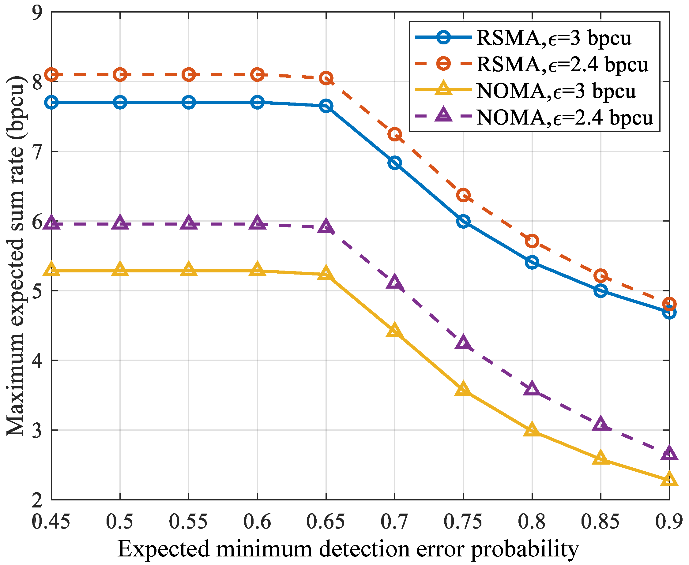
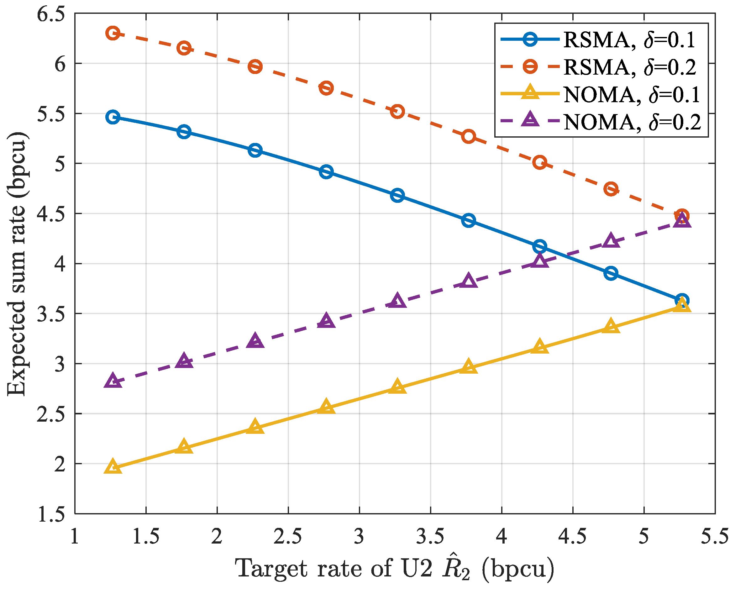
- The numerical results show that the proposed scheme outperforms NOMA systems in terms of ESR with the same DEP and ECR and illustrate the effect of constraints on the ESR.
2. System Model
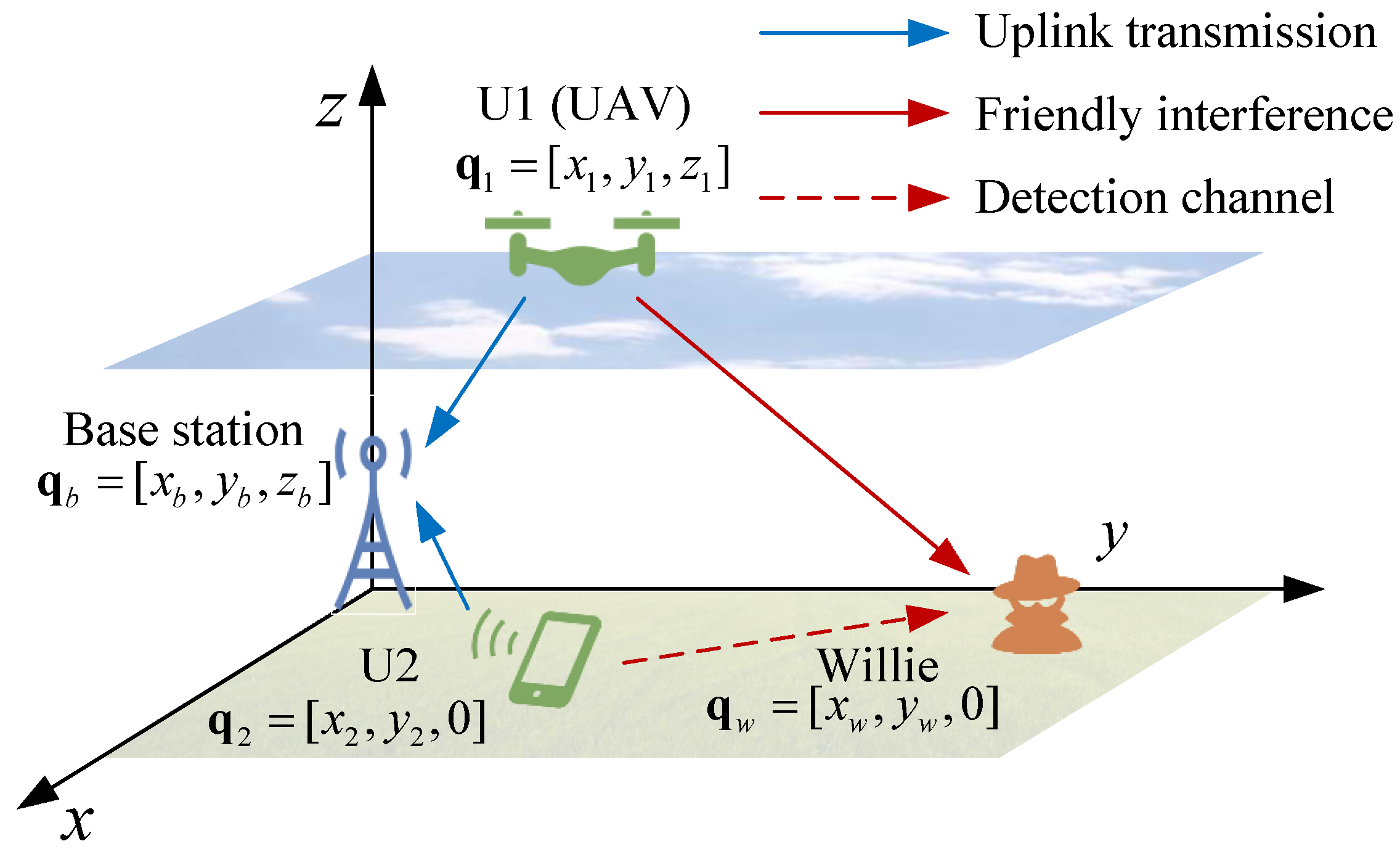
2.1. Communication Scenario
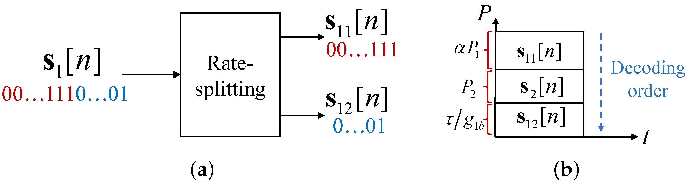
2.2. Proposed Transmission Scheme
2.3. Detection Metrics at Willie
3. Performance Analysis
3.1. Covertness Analysis
3.2. Sum Rate Analysis
- (1)
- UnderThe achievable rate under of is given byThus, the outage probability of under is expressed aswhere . Eventually, the ESR under is given by
- (2)
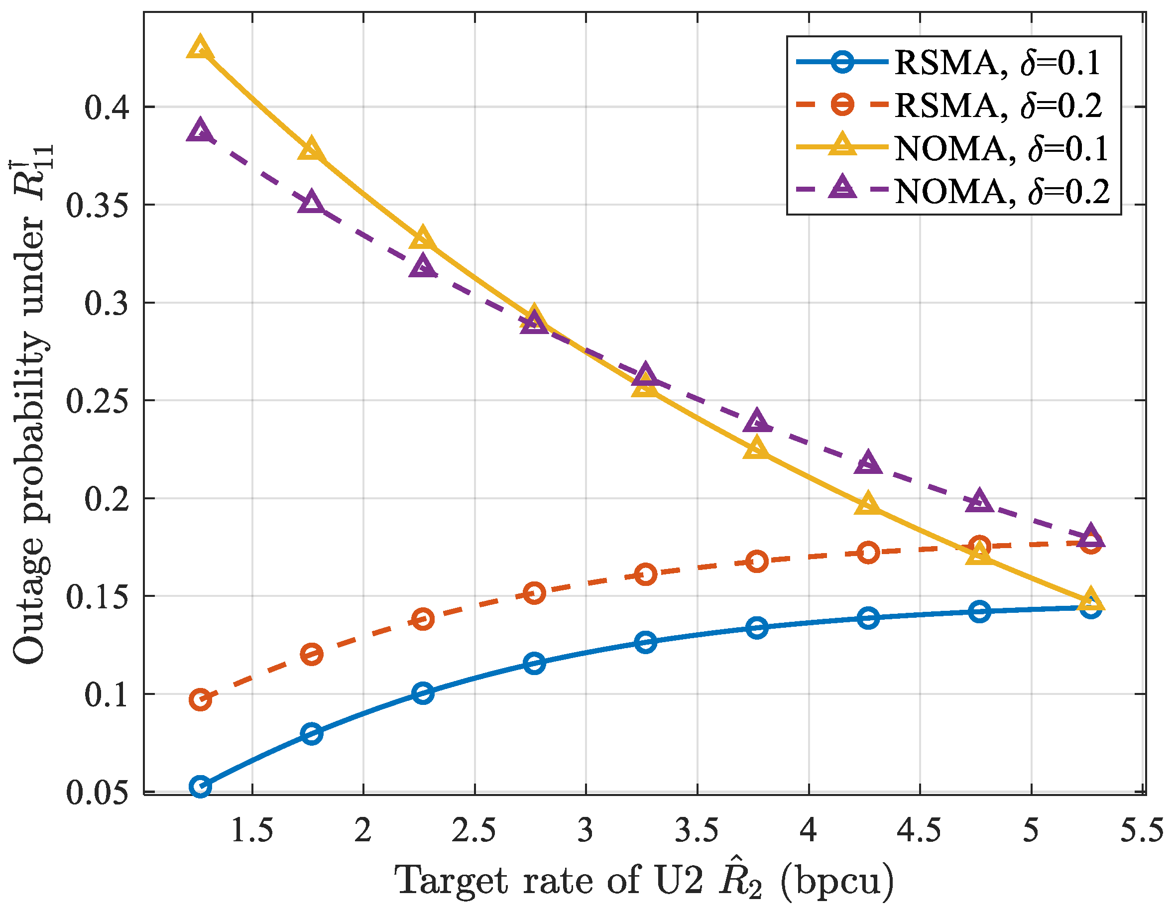
- UnderSimilarly, the achievable rate under of is given byAnd the outage probability of under is expressed asSince fixed power is allocated to to satisfy , . The ESR under is given byFinally, the ESR of the system is expressed aswhere , , , , and . Component is due to . Equation (20) demonstrates that as increases, the outage probabilities also increase, whereas the change in ESR is uncertain. Therefore, to maximize ESR, it is necessary to consider how to set .
4. Optimization Problem
5. Numerical Results
6. Conclusions
Author Contributions
Funding
Institutional Review Board Statement
Informed Consent Statement
Data Availability Statement
Conflicts of Interest
Abbreviations
| PLS | Physical layer security |
| AWGN | Additive white Gaussian noise |
| UAV | Unmanned aerial vehicle |
| RSMA | Rate-splitting multiple access |
| NOMA | Non-orthogonal multiple access |
| RS | Rate-splitting |
| BS | Base station |
| ESR | Expected sum rate |
| DEP | Detection error probability |
| 3D | Three-dimensional |
| CSI | Channel state information |
| LOS | Line-of-sight |
| SINR | Signal-to-interference-plus-noise ratio |
| LRT | Likelihood ratio test |
| FAP | False alarm probability |
| MDP | Miss detection probability |
| KKT | Karush–Kuhn–Tucker |
Appendix A. Proof of Lemma 1
Appendix B. Proof of Lemma 2
References
- Wang, D.; He, T.; Zhou, F.; Cheng, J.; Zhang, R.; Wu, Q. Outage-driven link selection for secure buffer-aided networks. Sci. China-Inf. Sci. 2022, 65, 1–16. [Google Scholar] [CrossRef]
- Lin, Z.; Lin, M.; Champagne, B.; Zhu, W.P.; Al-Dhahir, N. Secrecy-Energy Efficient Hybrid Beamforming for Satellite-Terrestrial Integrated Networks. IEEE Trans. Commun. 2021, 69, 6345–6360. [Google Scholar] [CrossRef]
- Bash, B.A.; Goeckel, D.; Towsley, D. Limits of Reliable Communication with Low Probability of Detection on AWGN Channels. IEEE J. Sel. Top. Signal Process. 2013, 31, 1921–1930. [Google Scholar] [CrossRef] [Green Version]
- Sobers, T.V.; Bash, B.A.; Guha, S.; Towsley, D.; Goeckel, D. Covert Communication in the Presence of an Uninformed Jammer. IEEE Trans. Wirel. Commun. 2017, 16, 6193–6206. [Google Scholar] [CrossRef]
- Wang, D.; Zhou, F.; Lin, W.; Ding, Z.; Al-Dhahir, N. Cooperative Hybrid Non-orthogonal Multiple Access-Based Mobile-Edge Computing in Cognitive Radio Networks. IEEE Trans. Cogn. Commun. Netw. 2022, 8, 1104–1117. [Google Scholar] [CrossRef]
- Lin, Z.; Lin, M.; Wang, J.B.; de Cola, T.; Wang, J. Joint Beamforming and Power Allocation for Satellite-Terrestrial Integrated Networks with Non-Orthogonal Multiple Access. IEEE J. Sel. Top. Signal Process. 2019, 13, 657–670. [Google Scholar] [CrossRef] [Green Version]
- Wang, D.; Wu, M.; He, Y.; Pang, L.; Xu, Q.; Zhang, R. An HAP and UAVs Collaboration Framework for Uplink Secure Rate Maximization in NOMA-Enabled IoT Networks. Remote Sens. 2022, 14, 4501. [Google Scholar] [CrossRef]
- Zhou, G.; Mao, Y.; Clerckx, B. Rate-Splitting Multiple Access for Multi-Antenna Downlink Communication Systems: Spectral and Energy Efficiency Tradeoff. IEEE Trans. Wirel. Commun. 2022, 21, 4816–4828. [Google Scholar] [CrossRef]
- Li, X.; Fan, Y.; Yao, R.; Wang, P.; Qi, N.; Miridakis, N.I.; Tsiftsis, T.A. Rate-Splitting Multiple Access-Enabled Security Analysis in Cognitive Satellite Terrestrial Networks. IEEE Trans. Veh. Technol. 2022, 71, 11756–11771. [Google Scholar] [CrossRef]
- Liu, H.; Bai, Z.; Lei, H.; Pan, G.; Kim, K.J.; Tsiftsis, T.A. A New Rate Splitting Strategy for Uplink CR-NOMA Systems. IEEE Trans. Veh. Technol. 2022, 71, 7947–7951. [Google Scholar] [CrossRef]
- Yang, Z.; Chen, M.; Saad, W.; Xu, W.; Shikh-Bahaei, M. Sum-Rate Maximization of Uplink Rate Splitting Multiple Access (RSMA) Communication. IEEE. Trans. Mob. Comput. 2022, 21, 2596–2609. [Google Scholar] [CrossRef]
- Lin, Z.; Lin, M.; de Cola, T.; Wang, J.B.; Zhu, W.P.; Cheng, J. Supporting IoT with Rate-Splitting Multiple Access in Satellite and Aerial-Integrated Networks. IEEE Internet Things J. 2021, 8, 11123–11134. [Google Scholar] [CrossRef]
- Lin, Z.; Lin, M.; Champagne, B.; Zhu, W.P.; Al-Dhahir, N. Secure and Energy Efficient Transmission for RSMA-Based Cognitive Satellite-Terrestrial Networks. IEEE Wirel. Commun. Lett. 2021, 10, 251–255. [Google Scholar] [CrossRef]
- Wang, M.; Yang, W.; Lu, X.; Hu, C.; Liu, B.; Lv, X. Channel Inversion Power Control Aided Covert Communications in Uplink NOMA Systems. IEEE Wirel. Commun. Lett. 2022, 11, 871–875. [Google Scholar] [CrossRef]
- Lv, L.; Wu, Q.; Li, Z.; Ding, Z.; Al-Dhahir, N.; Chen, J. Covert Communication in Intelligent Reflecting Surface-Assisted NOMA Systems: Design, Analysis, and Optimization. IEEE Trans. Wirel. Commun. 2022, 21, 1735–1750. [Google Scholar] [CrossRef]
- Yan, S.; Hanly, S.V.; Collings, I.B. Optimal Transmit Power and Flying Location for UAV Covert Wireless Communications. IEEE J. Sel. Areas Commun. 2021, 39, 3321–3333. [Google Scholar] [CrossRef]
- Rao, H.; Xiao, S.; Yan, S.; Wang, J.; Tang, W. Optimal Geometric Solutions to UAV-Enabled Covert Communications in Line-of-Sight Scenarios. IEEE Trans. Wirel. Commun. 2022, 21, 10633–10647. [Google Scholar] [CrossRef]
- Su, Y.; Fu, S.; Si, J.; Xiang, C.; Zhang, N.; Li, X. Optimal Hovering Height and Power Allocation for UAV-aided NOMA Covert Communication System. IEEE Wirel. Commun. Lett. 2023, 1–5. [Google Scholar] [CrossRef]
- 3GPP. Technical Specification Group Radio Access Network; Study on Channel Model for Frequencies from 0.5 to 100 GHz (Release 14); Technical Specification (TS) 38.901; Version 14.3.0; 3rd Generation Partnership Project (3GPP). 2018. Available online: https://www.etsi.org/deliver/etsitr/138900138999/138901/14.00.0060/tr138901v140000p.pdf (accessed on 6 March 2023).
- Zhou, X.; Yan, S.; Shu, F.; Chen, R.; Li, J. UAV-Enabled Covert Wireless Data Collection. IEEE J. Sel. Areas Commun. 2021, 39, 3348–3362. [Google Scholar] [CrossRef]
- Shahzad, K.; Zhou, X.; Yan, S.; Hu, J.; Shu, F.; Li, J. Achieving Covert Wireless Communications Using a Fulsl-Duplex Receiver. IEEE Trans. Wirel. Commun. 2018, 17, 8517–8530. [Google Scholar] [CrossRef] [Green Version]
- Corless, R.M.; Gonnet, G.H.; Hare, D.E.; Jeffrey, D.J.; Knuth, D.E. On the Lambert W function. Adv. Comput. Math. 1996, 5, 329–359. [Google Scholar] [CrossRef]


Disclaimer/Publisher’s Note: The statements, opinions and data contained in all publications are solely those of the individual author(s) and contributor(s) and not of MDPI and/or the editor(s). MDPI and/or the editor(s) disclaim responsibility for any injury to people or property resulting from any ideas, methods, instructions or products referred to in the content. |
© 2023 by the authors. Licensee MDPI, Basel, Switzerland. This article is an open access article distributed under the terms and conditions of the Creative Commons Attribution (CC BY) license (https://creativecommons.org/licenses/by/4.0/).
Share and Cite
Duan, Z.; Yang, X.; Zhang, T.; Wang, L. Optimal Position and Target Rate for Covert Communication in UAV-Assisted Uplink RSMA Systems. Drones 2023, 7, 237. https://doi.org/10.3390/drones7040237
Duan Z, Yang X, Zhang T, Wang L. Optimal Position and Target Rate for Covert Communication in UAV-Assisted Uplink RSMA Systems. Drones. 2023; 7(4):237. https://doi.org/10.3390/drones7040237
Chicago/Turabian StyleDuan, Zhengxiang, Xin Yang, Tao Zhang, and Ling Wang. 2023. "Optimal Position and Target Rate for Covert Communication in UAV-Assisted Uplink RSMA Systems" Drones 7, no. 4: 237. https://doi.org/10.3390/drones7040237