1. Introduction
Drone technology has become inexpensive and accessible as a result of the continuous evolution and development observed over the last two decades. Numerous application domains emerged, ranging from aerial photography and disaster management over precision agriculture, shipping and delivery and mining to wildlife monitoring, law enforcement or military operations [
1,
2,
3,
4,
5].
The cheap operational time of unmanned multi-copter drones becomes a significant advantage when compared to conventional aerial vehicles. On the other hand, the maximum flight duration in the order of tens of minutes might be the most limiting factor in many applications. This limitation comes from the maximum capacity of lithium-based batteries supplying power for most electrically-propelled drones. Unlike ground vehicles, the maximum flight range cannot be scaled simply by installing larger batteries since a maximum take-off weight and power consumption limits must also be considered [
6,
7,
8,
9]. While increasing the power density of the power source can potentially bring some performance improvements, novel battery technologies are still far from widespread commercial adoption [
10,
11,
12].
Manual battery replacement by humans to keep the drone operational is generally not suitable while pursuing the ultimate goal of autonomous operation and cost-effective deployment. Therefore, there were many attempts to automate the recharging process without the necessity of human intervention [
13,
14,
15,
16]. Nevertheless, the long waiting time that leaves the drone grounded poses a significant drawback of this approach. Tethering the drone with a power station has been proposed as an alternative [
17,
18]. However, the physical connection of the drone with the ground is infeasible for many applications due to the inherent consequences for take-off weight and flight range.
Introducing an automatic station allowing battery replacement seems to be a more convenient option. Several experimental systems were reported in the literature [
19,
20,
21,
22,
23]. Few commercial solutions have already been introduced to the market [
24,
25,
26,
27,
28], mostly intended for a particular drone type. The emerging technology dealing with storing, deploying and recharging the drone using a single container is commonly designated as
drone-in-a-box. The goal is to improve the aerial vehicle’s autonomy and safety while simplifying its utilisation. Automatic battery swapping or charging becomes an essential feature of such systems.
The paper deals with our proposed system, called Droneport (DP), which is designed to operate various drone types with Vertical Take-Off and Landing (VTOL) ability. The main functionality it brings is an automatic process of rapid battery swapping and charging, allowing fast return of the drone to its mission. The DP is equipped with a battery management system dealing with battery storage, identification and health evaluation. Unlike the above-mentioned commercial systems, DP is developed as an open-source solution, with a published source code for the traffic controller, MAVLink API description, etc. A link to the project repository is provided in the
Appendix A.
Droneport was already introduced in our previous publications [
29,
30], where the software and simulation tools were described in detail. The process of prototyping was described in [
31]. The current paper extends the former results. It expands on hardware and software development details and provides a previously unpublished overview of the Droneport control system. The paper is organized as follows.
Section 2 introduces the mechanical design of the Droneport, describing a robotic manipulator responsible for battery swapping.
Section 3 deals with the description of HW and SW components of the system, focusing mainly on custom-designed gripper.
Section 4 describes a real-time software environment used to implement the control system.
Section 5 reveals the algorithmic and implementation details of the developed control system. This part constitutes the main contribution with respect to the previously reported results. Concluding remarks are given in
Section 6.
2. Mechanical Concept and Design
The main goal was to develop a drone battery swapping system fulfilling a few fundamental objectives:
automatic battery charging and swapping without any human intervention;
extension of the UAV operational time from minutes to hours;
simple communication protcol based on MAVLink standard;
compact construction and easy handling;
reasonable purchasing/maintenance cost.
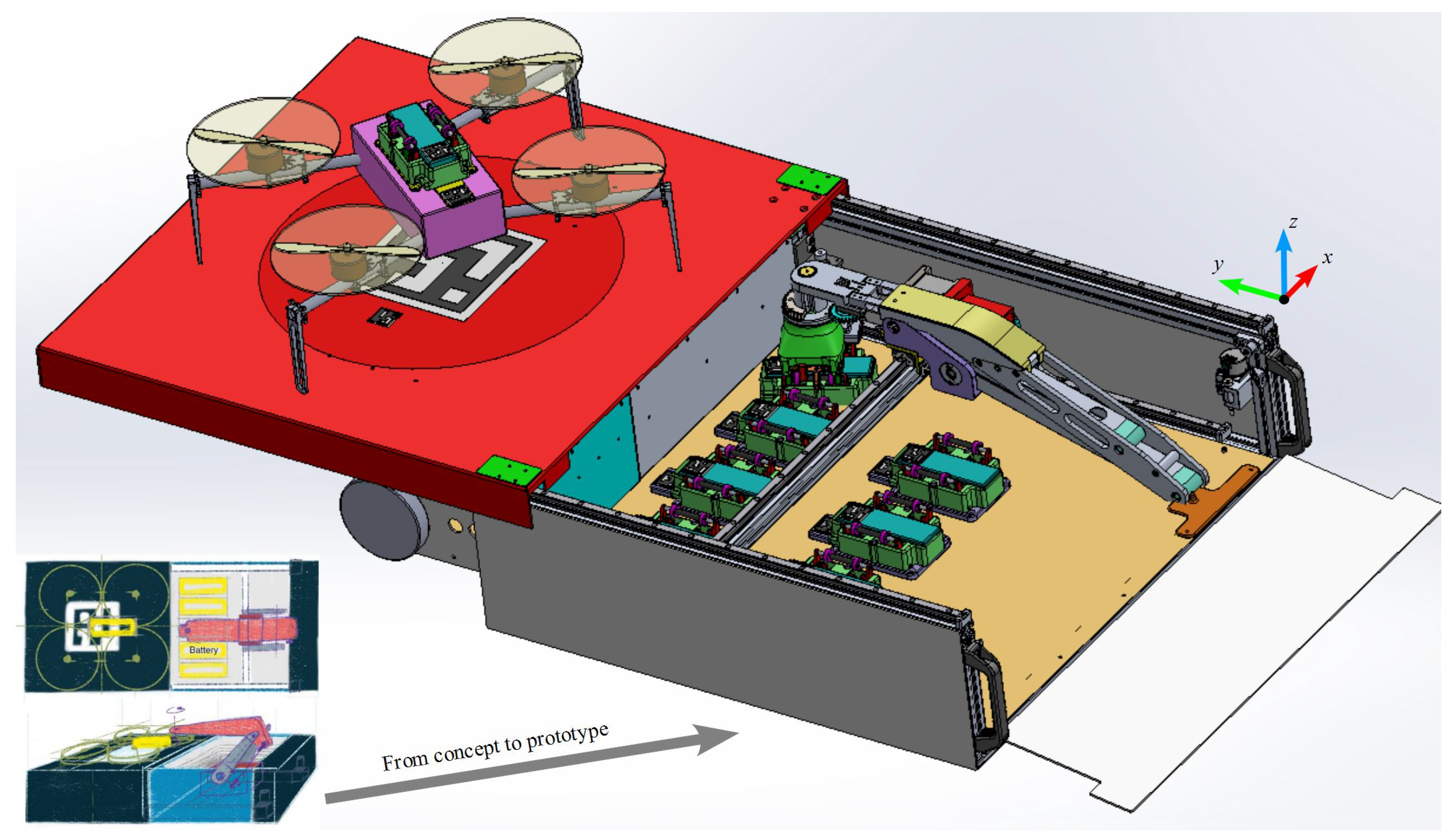
These objectives led us to the Droneport architecture, which was designed as a landing platform covering the charging station and a special robotic manipulator arm for the necessary contact with the landed drone, see
Figure 1. The following subsections describe the conceptual details.
2.1. Droneport Mechanics
Droneport employs a special robotic manipulator with a parallelogram structure, which is responsible for automatic battery swapping. The parallel manipulator structure is able to reduce the number of actuators, minimise the amount of moving inertial mass and provide the required manipulation workspace. This results in compact design providing easy handling. The robot links-length were optimized using a min-max discrete optimization algorithm, described in [
32]. The goal was to derive optimal manipulator arm lengths with respect to demands on force/torque and acceleration limits in a given workspace. The manipulator consist of three distinctive mechanical subsystems:
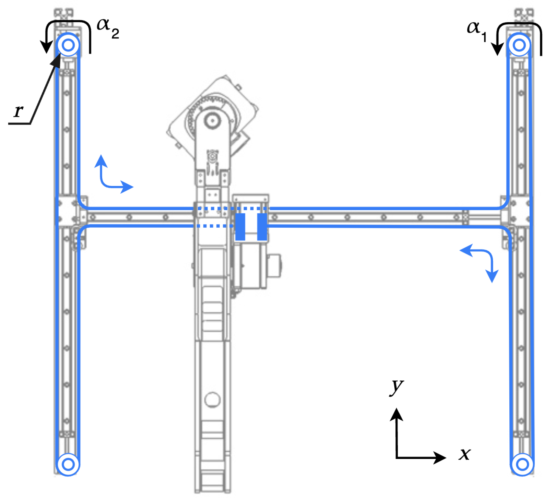
Planar moving base—the H-bot structure helps to reduce the moving mass by fixing the actuators to the machine support and connecting them to the manipulator via tooth belt, see [
33] and
Figure 2.
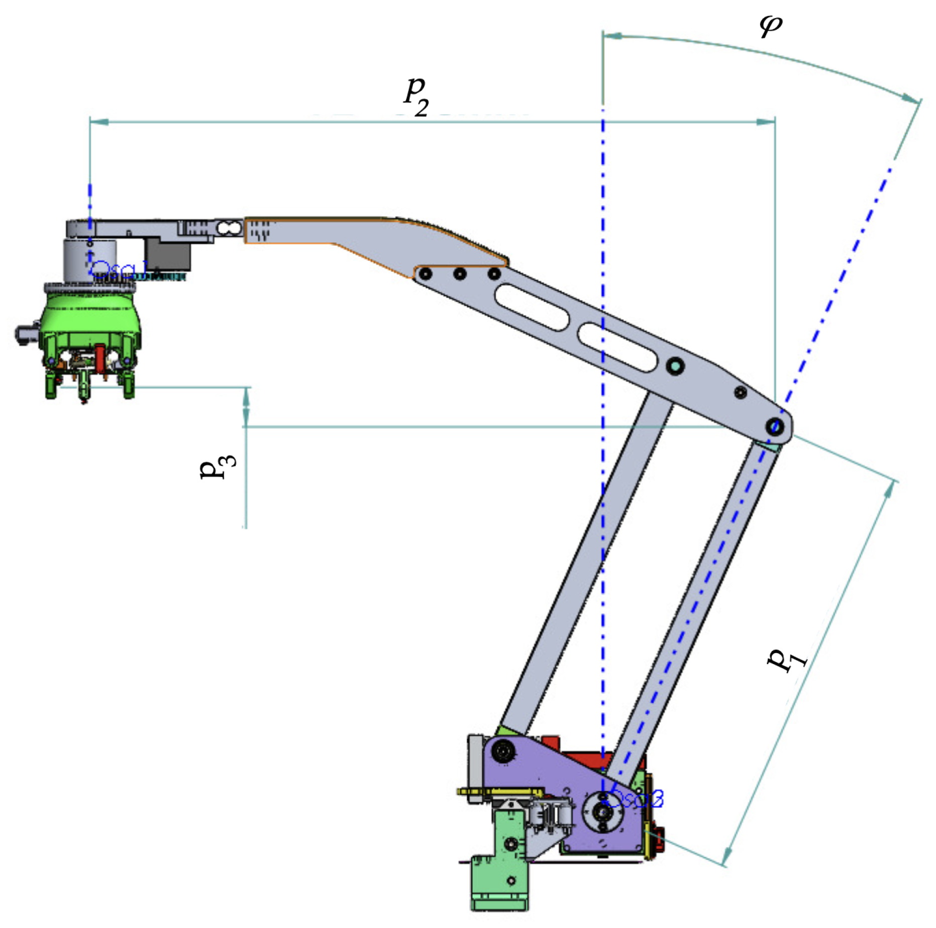
Parallelogram structured arm—a lightweight planar linkage with a parallel structure, driven by a stepper motor with worm wheel gear in its base, detailed in
Figure 3.
Battery gripper—a gripper designed to securely attach and detach the battery, transport the battery from and to the charger slots and ensure the connections checks.
Section 3.2.1 describes the gripper in detail.
The chosen kinematic structure allows to achieve a favourable reach to weight ratio. The manipulator arm is able to fold itself to the Droneport box as well as reach the battery of the landed drone, as depicted in
Figure 4.
2.2. Droneport Kinematics and Workspace
Kinematics of the manipulator can be described as the relation between joint space coordinates
and workspace coordinates
in the form
where
r is a radius of the belt pulleys in the H-bot base,
k is a gear ratio between orientation of gripper
and its actuator
, and
are parameters of manipulator as depicted in
Figure 3. For the tilt angle
from range (−100°, 100°), there exist two solutions converging to one in the upright position. The Jacobian matrix
defines the relation between joint coordinates and end effector coordinates in the form
more precisely
The resulting singularity in the upright position of the manipulator parallel arm has to be overcome via motion in joint space. The robot workspace can be described in an x-z plane as a polygon with boundaries which are given by reach limits and structure collisions. This polygon is relevant at each shift in the y-axis and all orientations. Thus, the manipulator is able to move above the drone such that the battery gripper is still parallel to the landing platform, and can be turned to align with the drone battery holder.
The Jacobian from Equations (
2) and (
3) also defines the relation between the velocities of joints and the end effector, respectively,
The impact of the worm wheel backlash has to be evaluated in order to validate achievable positioning accuracy. As shown in [
31], the end effector position error varies along the tilt angle and the maximum position error is about 6 mm on each degree of backlash.
The backlash was found to be the main factor influencing the manipulator’s accuracy because the belt tension, bearings clearance and material rigidity are negligible in comparison to the gear clearance. These findings led us to the addition of capabilities to measure and control the contact force vector. This is achieved by changing the actual position of the gripper jaws with respect to battery holder alignment pins, see
Section 5 devoted to Droneport control for more details.
3. Hardware Parts Specification and Functional Properties
3.1. Main Computer, Peripherals and Power Management
The DP consists of several modules, which are orchestrated using an UpBoard UP Xtreme computer with an Intel Core i3 processor. The computer is interconnected with the following components, depicted in
Figure 5:
Power supply, protection and distribution—230 V AC input, 24/12 V DC outputs,
manipulator drives via CANopen communication,
gripper via serial line communication over USB,
gripper camera via USB communication,
battery charger via serial line communication over USB,
additional DI/DO via real-time EtherCAT gateway,
Droneport interface via MAVLink communication protocol over Ethernet using UDP packets.
3.2. Battery Transportation and Gripping
Nowadays, batteries and their connections to drones have no standardization. Each company has its own system of connections, battery placing, etc. Most systems are not suitable for precise and secure gripping of the battery by the robot arm. Moreover, the connections of high-current connectors are intricate to push or pull, even for human operators. Therefore, a unified system for the battery case and holder reconnecting is developed and examined in the following subsection.
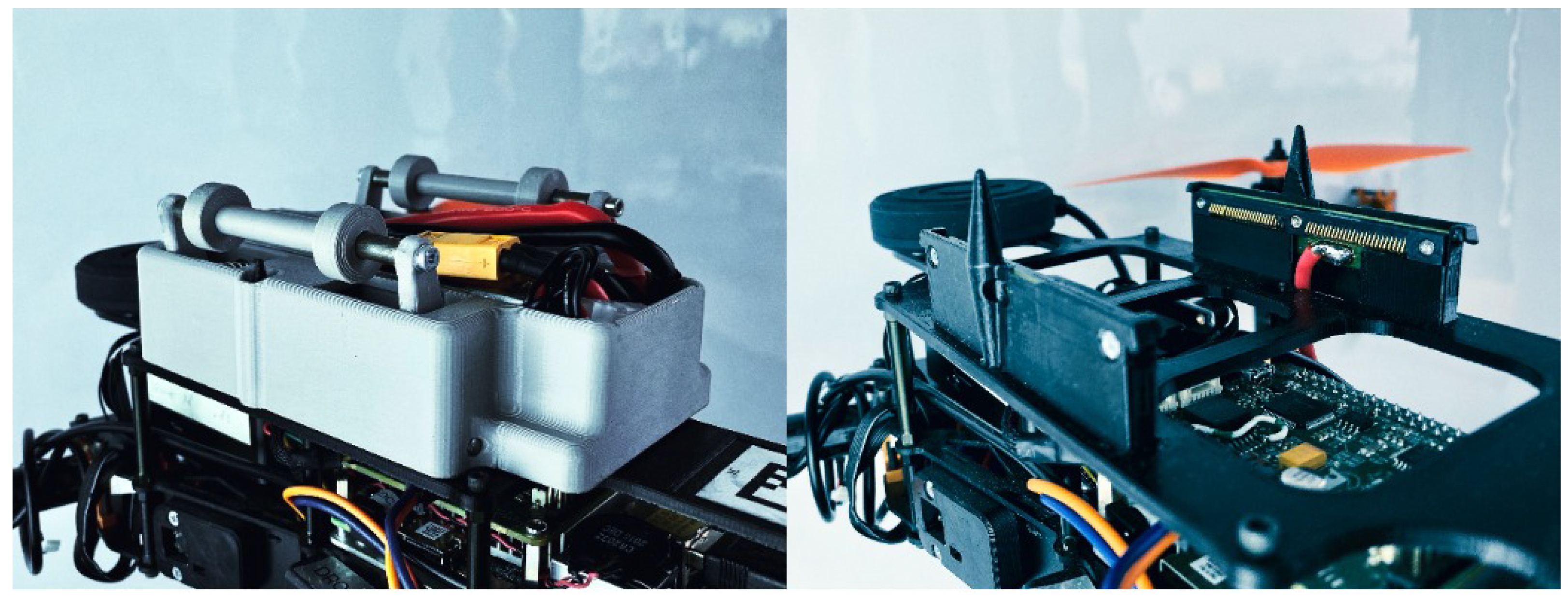
3.2.1. Battery Case and Holder
The goal was to design a special case for a standard Li−Po battery, which the automatic swapping system can easily replace. The XT-60 connector is commonly used for standard size batteries. It is reliable and capable of high currents. Unfortunately, it is challenging to connect and reconnect this connector manually, let alone automate this process with a robot. Therefore, designing a unique battery case and holder for a standard Li-Po battery was a necessary step.
The drone battery encapsulated in a unified case is assumed to be placed on top of the drone body to make it easily reachable by the robot arm. The case contains the battery slot, the two pin-hole centring system, two levers for gripping and two types of connections. The spring pin connector is intended for monitoring the cells and other diagnostic purposes. Conductive plates serve for high power distribution. These two conductive lines and spring pin connector fit securely to a custom design battery holder with a conductive complement in the form of 2 × 30 pins spring connector. Disconnection is provided via mentioned levers driven by gripper jaws. The only horizontal force is needed to disconnect the electrical connection. It also releases the battery case from the holder, which is then free to be pulled up from the alignment pins. A couple of springs in the battery case realize the necessary contact force for high power distribution during flight.
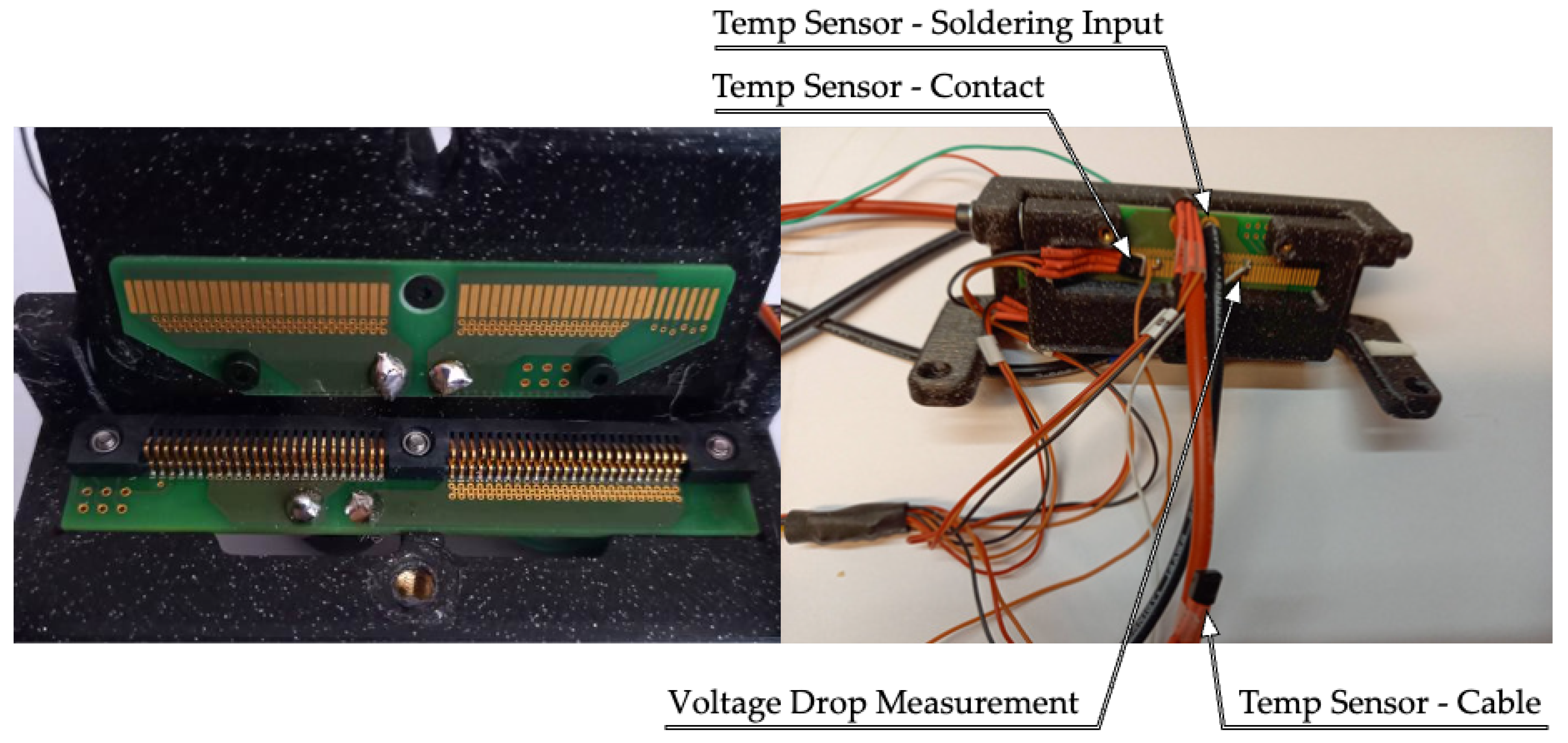
Figure 6 shows the battery case and holder, including some safety features such as polarity control, short circuit protection due to improper handling, etc. An ArUco code as a unique ID of the holder is used for drone/battery recognition and visual targeting. This setup has been tested for a 60 Amp continuous current, see
Figure 7,
Figure 8 and
Figure 9, which covers some testing results.
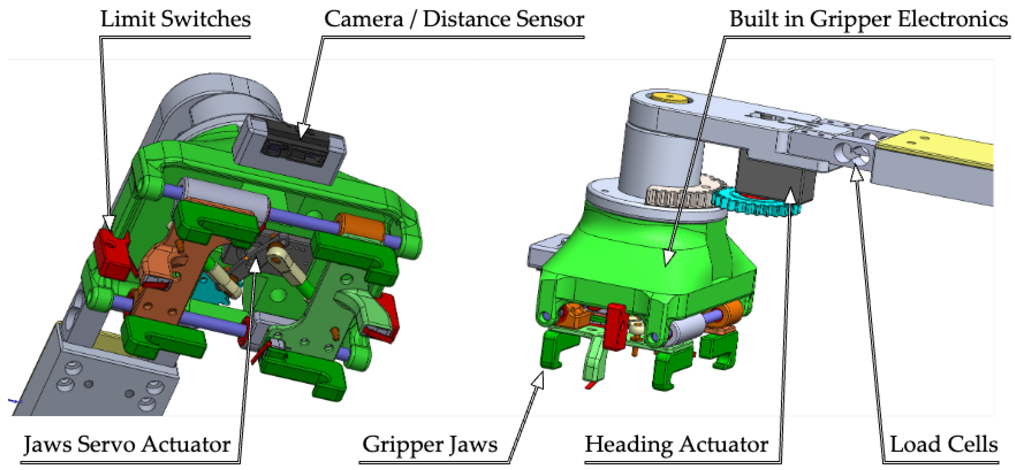
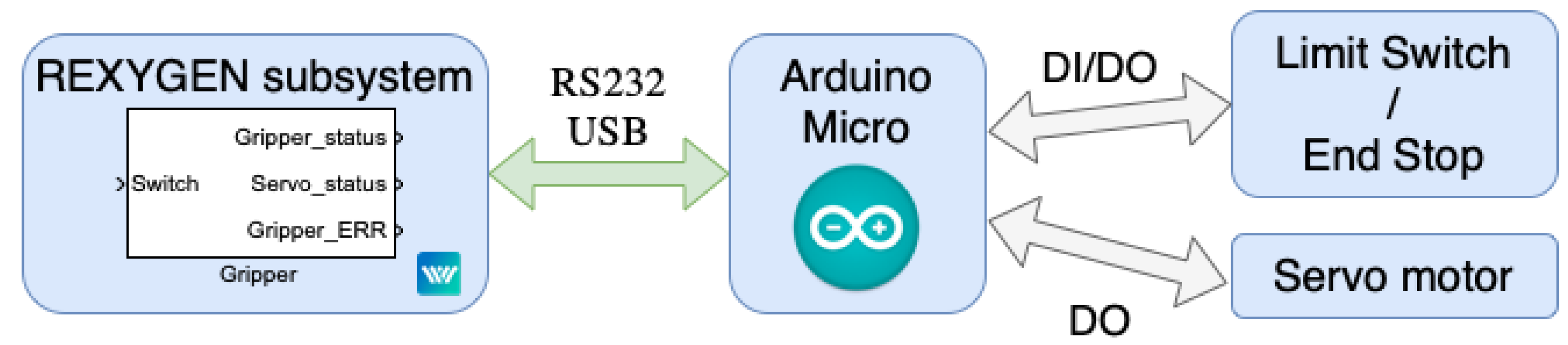
3.2.2. Gripper
A gripper was developed as a complementary part of the battery holder. It consists of several components depicted in
Figure 10. The linear guide rollers of the gripper jaws are controlled by a RC servo. A built-in microcomputer in the form of an Arduino micro manages the servo commands and deals with the limit switches for detecting the current position of the jaws and established contact with the battery holder. A range finder and a web camera are intended for targeting the ArUco marker and searching and estimation of the battery holder position with respect to the manipulator. A custom control block that performs the gripper operations was also designed, see
Figure 11.
4. Software Environment
The main computer uses Debian-based Linux OS with real-time kernel capabilities. The REXYGEN software developed and maintained by REX Controls company [
34] was chosen as a real-time control system for the whole application.
The system includes a development environment supporting a graphical function block language without the need to write code manually. This is close to the workflow of Mathworks’ Matlab-Simulink or the industrial PLCOpen IEC 61131-3 standard. An extensive library of ready-to-use functional blocks is available. Their functionalities range from the most basic logic operators, amplifiers or timers to advanced blocks used for signal processing or feedback control. If needed, the user can also write a custom function block using RexLang, a scripting programming language similar to C. High-level programming via Python is also possible.
The system allows managing the whole control application with the capability to divide it into different tasks with various priority levels and sampling times. A real-time scheduler then assigns the CPU time accordingly to achieve the correct functionality of the whole application while meeting the timing deadlines of the individual tasks.
REXYGEN development studio can be used on a regular PC or laptop, where the algorithms can be compiled. Once running, either on a PC or connected to the target hardware, the control process can be watched in real time. It is also possible to check the calculation speed of the individual algorithms in the system. Connection to the target software can be made via a local network or the Internet. REXYGEN supports a wide range of communication protocols such as CAN/CANopen, Ethernet, EtherCAT, Modbus, Profinet and others. MAVLink protocol is also supported and beneficially used in this project.
The system also offers tools for creating human-machine interfaces which can run on a PC, tablet or smartphone. The interface is then embedded with the project and copied to the target control hardware.
The advantage of REXYGEN is its affordability and a wide range of supported target platforms. More detailed specifications can be found on the website:
https://www.rexygen.com (accessed on 27 March 2023).
The Linux-based operation system with real-time Linux kernel patch allows precise planning of periodic functions. However, for control tasks, one needs an application that can benefit from these functions. The REXYGEN system was chosen because our team can easily influence development. The REXYGEN allows us to separate control to several tasks which are run in real-time. Additionally, the DP contains several HW components (see
Figure 5) with various communications protocols (RS232, EtherCAT, HTTP, MAVLink, etc.); thus, we needed the bridge between them.
5. Droneport Control
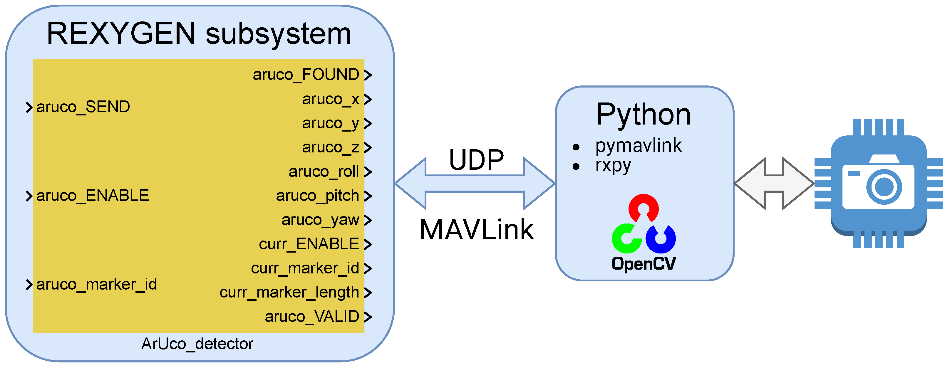
The control system is developed using function block diagrams language in the REXYGEN software. It is divided into several real-time tasks, which run with different sampling periods. In parallel, there is a standalone application for image processing from the gripper camera written in Python and OpenCV. The data connection between the standalone application and the main control algorithm is established via UDP packets over MAVLink protocol. For example, the wrapper of the MAVLink interface for image processing app communication is shown in
Figure 12.
The REXYGEN is used for the real-time task, but it lacks the support of image processing; thus standalone application for ArUco detection was developed. There was a need for data exchange. Since the MAVLink over UDP is widely used for commanding the drone and it supports message specification for vision messages, it was decided to use this means of data exchange. Moreover, Python is suitable for fast software prototyping, so this stand-alone module is based on it.
The following subsections contain the description of the control structure with respect to schematics diagrams, control blocks and subsystems, and the technology of commands and control.
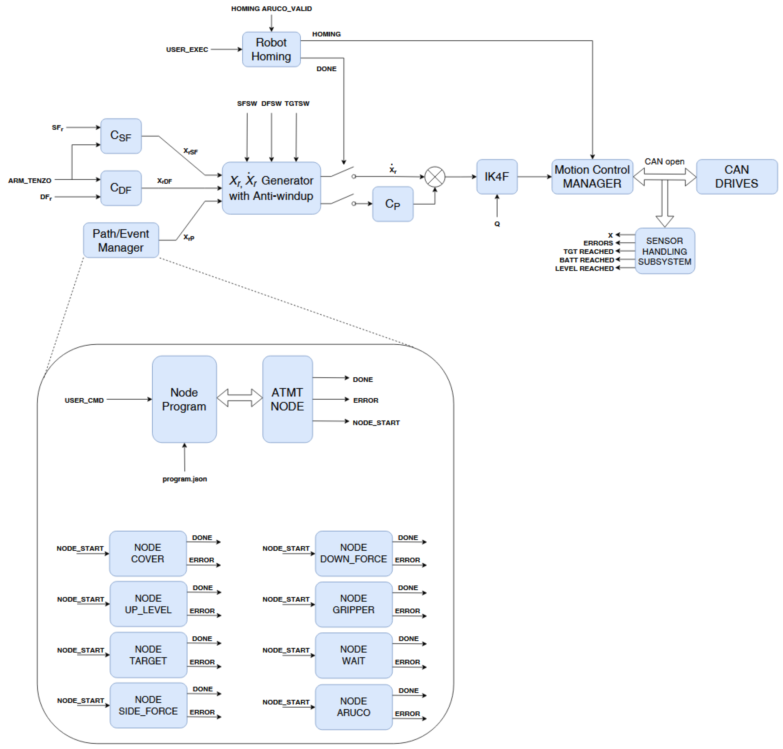
The control system is divided into two main parts. The first one is responsible for the control of low-level functions such as manipulator movements, communication with the charger, control of the landing platform, etc. The second part is a high-level controller named Event/path manager, which is used for orchestrating all the actions together with error handling, see
Figure 13 for details.
5.1. Low Level Control/Motion Control
Control of robot axes is based on PLCopen Motion control standard [
35]. The Motion Control Manager (MCM) contains functional blocks representing all the robot Axes, called
. These blocks keep all status values and implement a basic algorithm controlling the state of one motion control axis (physically one drive), which includes limits checking, emergency stop, etc. MCM is responsible for generating the appropriate reference motion trajectories to the drive with a defined sampling period, respecting the axis limits, etc. The axes coupling to coordinated motion is based on the computation of the inverse kinematics (Equation (
5)), which is implemented in block
IK4F. The velocity reference for each motion axis is generated by this block according to the current state
keeping in mind the singularity that should be avoided.
Above that, a feedback control scheme in the extended cascade structure is created, as depicted in
Figure 13. This cascade contains the position controller, which is commanded by the position generator with anti-windup switching. The switching is performed according to the demands on actual motion behaviour. This means the ability to switch between the motion to the target
, motion according to the down-force and/or side-force commands or their combinations. These references are produced by a couple of force controllers
and via high-level commands. These commands come from a high-level controller, which orchestrates the motion generator according to the actual demands on motion, contact forces, HMI, etc. The force control algorithm can be designed using the method proposed in [
36].
5.2. High Level Control—Path/Event Manager
The whole Droneport system consists of several discrete components which must be orchestrated together. As shown in
Figure 5, several subsystems are connected via various communication busses. In addition, the communication process between drone and Droneport must be taken into account. Therefore, the simple closed-loop control is unsuitable for such a task. We have to use event-based distributed closed-loop control. REXYGEN system does not implement distributed control based on the IEC61499 norm, but several blocks can be used for such types of control algorithms. The finite-state automaton (ATMT) is a typical example. This block interprets a sequential function chart (SFC) with states and transitions and is widely used for event-based sequence programming. Another special block can parse the .JSON configuration file (PJSOCT) and interpret the simple Python script. By combining the .JSON configuration, sequential function graphs, and close loop control, one can achieve a suitable event-based controller. The high-level hierarchy is described in the following sections.
5.3. Schematic Diagrams of Main Control Blocks
This section contains the control scheme of all main compute/control modules or blocks which are responsible for the functionality of the whole system.
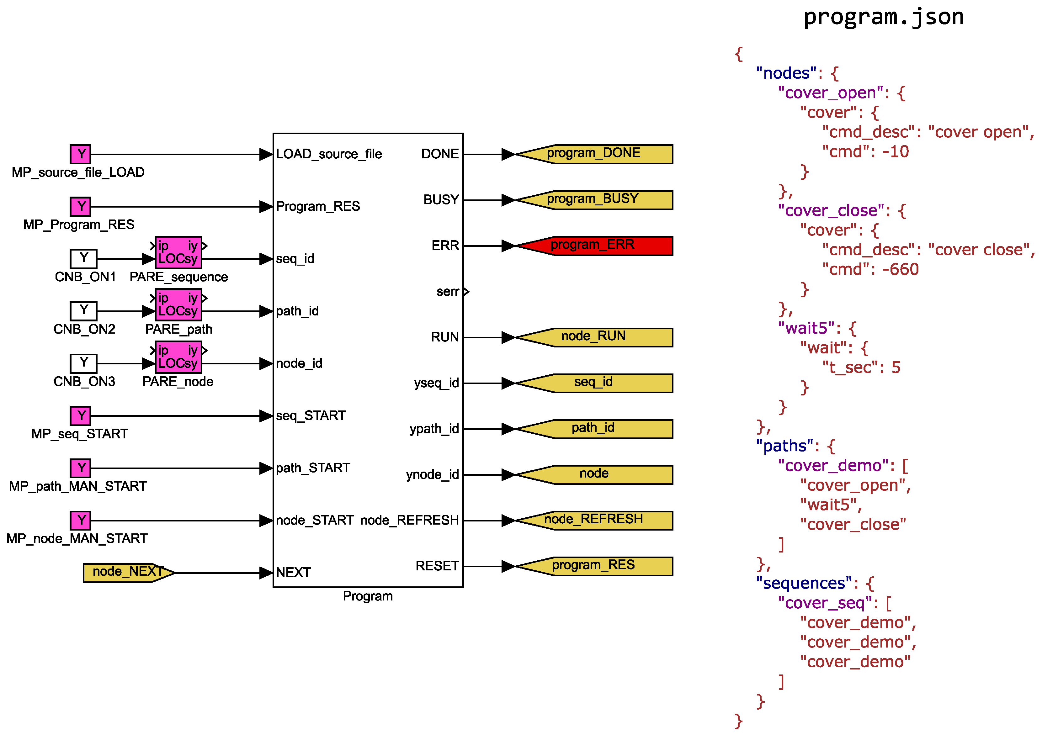
High-level control consists of several discrete actions that can be done in series or in parallel. These actions cover the positioning of the landing platform, positioning of the manipulator, the management of the battery holders and charger state, etc. One can imagine this high-level control as an oriented graph. Each node represents a set of parameters for multiple low-level tasks. The node also contains each task’s start and end conditions. Selected nodes can be interconnected to a chain named path. The parameters for the nodes and the description of paths are stored in one .JSON file.
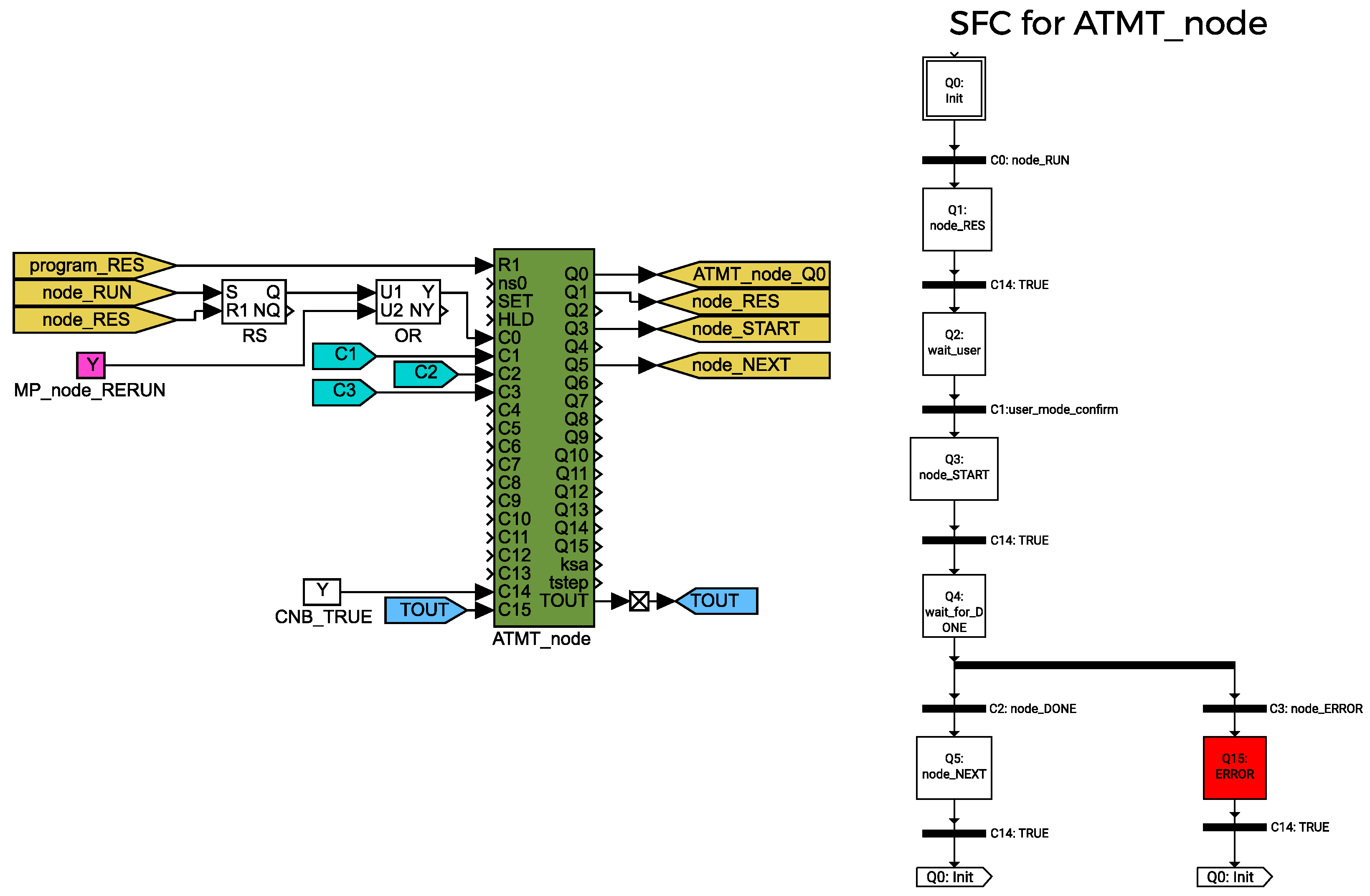
As shown in
Figure 14, when the controller is started, the .JSON configuration file is loaded to the
Program subsystem. This subsystem loads selected
path from the
paths .JSON object, and when started, it provides the first
node dataset to the
ATMT_node block (see
Figure 15). The
ATMT_node block checks the input conditions for the given node and initiates the
node_START pulse. This pulse is transferred to each action subsystem. The action can be waiting for a defined time, manipulator movement, closing or opening the gripper, etc. Each node can have multiple actions which are done in parallel. Each action is represented by a subsystem named
Node_ as a prefix, e.g.,
Node_wait,
Node_aruco,
Node_gripper, etc.
Each action/node subsystem has a common interface and ATMT block. When node_START pulse is activated, each action node checks if the call is valid for the given action. After that, the whole program/path/node waits until all the parallel actions end with a done flag or with an error flag. If an error occurs, the action is stopped at the current state, path fails, and an error handling algorithm has to be called. If all actions are executed, the ATMT_node receives the next node from the current path and the executing process is called again. This continues until all nodes from the selected path are accomplished. The program can combine multiple paths into the sequence (path of paths) to cover some high-level operations.
5.4. Battery Replacement Process
Path/event manager nodes are listed here and described to better understanding the battery replacement motion control process. A typical drone battery transport looks as follows:
- (1)
drone lands on the platform
- (2)
cover is opened
- (a)
is executed
- (3)
manipulator moves above the drone
- (a)
sequence of multiple nodes are executed in serial
- (4)
manipulator performs the ArUco searching process to localize the drone battery case
- (a)
search is executed
- (5)
manipulator performs a contact approach to the battery
- (a)
Gripper is open via node
- (b)
Approach is done via
Force control is performed via and
- (6)
battery is pulled out from the battery slot
- (a)
Gripper is closed via node
Force control for precise horizontal positioning is turned on via
- (b)
Motion above the actual position done via
Force control for smooth pulling motion is done via
- (7)
battery is transferred above empty charging slot
- (a)
sequence of multiple nodes are executed in serial
- (8)
battery is placed to the charging slot
- (a)
is performed with known parameters of slot position
and are turned on for precise leveling
- (b)
Gripper is open via node to place the battery
- (c)
is performed to move safely back above the charging slot
remains turned on for precise leveling
5.5. Node Examples
5.5.1. Node Wait
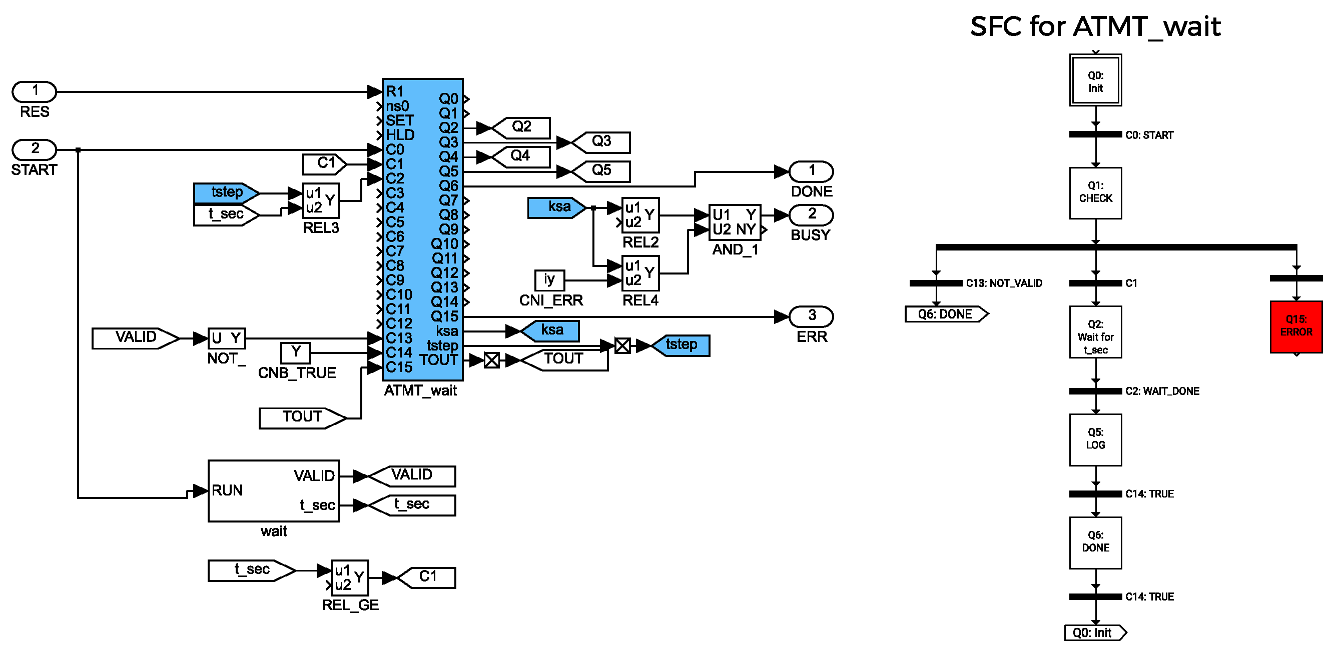
For example, the subsystem for processing the simple
Wait (one parameter
t_sec—for how long should this
node wait) node is depicted in
Figure 16. Each
node subsystem has a similar interface. There is an ATMT block for SFC processing, a special subsystem for parsing nodes parameters and a standardized input/output interface. Whenever the node is executed, the ATMT block checks if the parameters are valid, then starts the activity and waits for the result, in this case, when the t_sec time passes. Then the
DONE signal is set. In case of error, the
ERR output is set and the ATMT state remains in error until the node is reset. Examples of the SFC for
ATMT_wait are also shown in
Figure 16.
5.5.2. Node ArUco Searching
Each drone battery holder has a unique ArUco Marker with given ID. Each ID has assigned a mapping from marker position to position where the battery gripper should await for the battery holder. Sensing of actual battery holder position on the drone is given by sensed ArUco Marker position with a given spatial transformation in the form of
where
is the new drone battery holder position computed from actual gripper position
in global frame and actual ArUco Marker sensing vector
with given offsets
. This offset is given by actual ArUco Marker placement on the battery holder plate, defined for each Marker ID. The actual location of the drone battery holder is based on the following search Algorithm 1.
| Algorithm 1: ArUco searching algorithm |
Init: k = 0 Output: manipulator new target position for node_TARGET WHILE not found and k < 10 DO Perform another search motion according to the equations
|
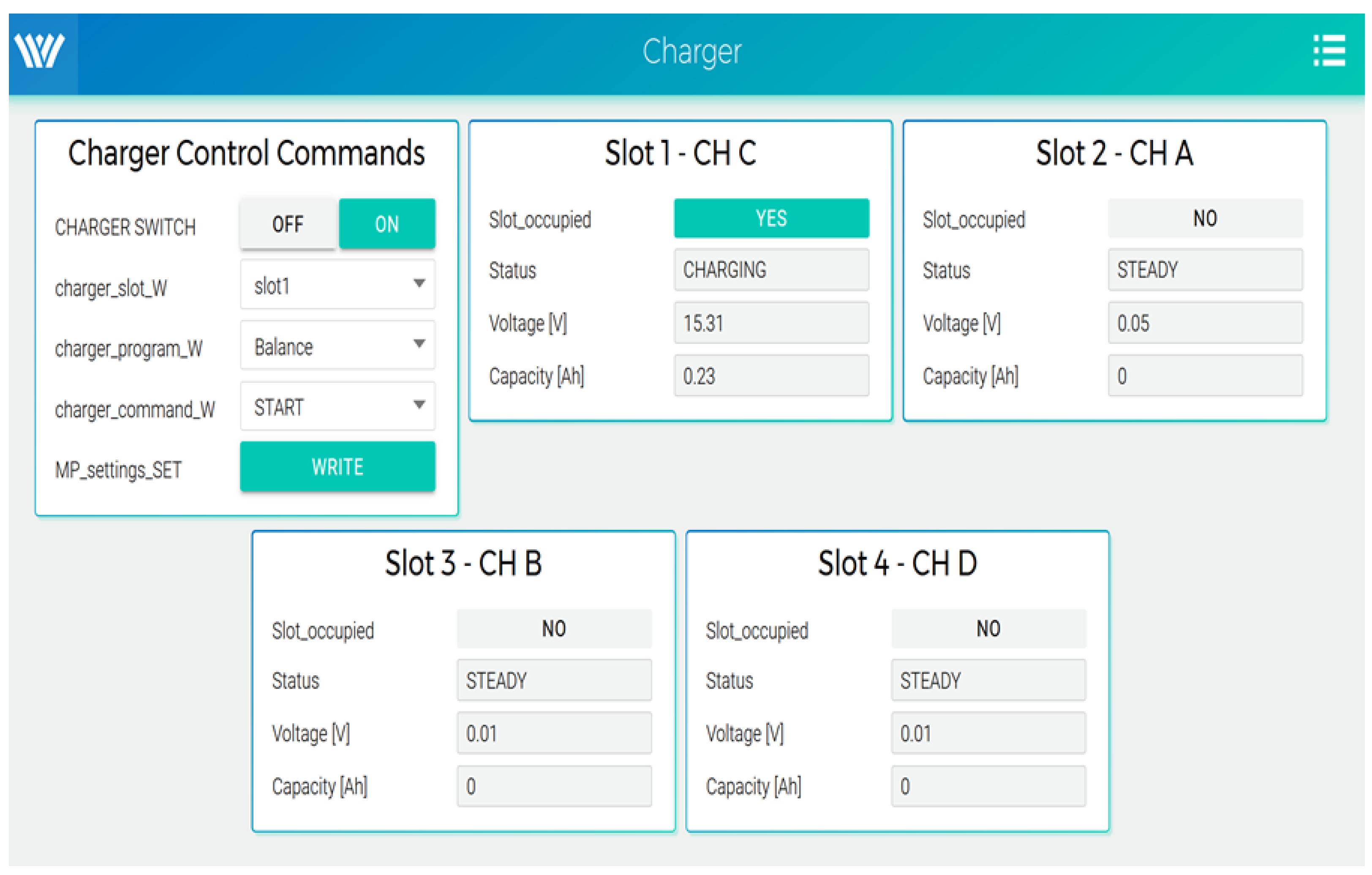
5.6. Battery Charging Management
Since the DP is a prototype device, we chose a widespread battery type for medium-sized drones. It is a LiPo battery with four cells (4S). The battery compartment and the charging position are designed for this type of battery. Since these are the standard type of RC batteries, we were looking for an affordable charger that would allow operating multiple batteries simultaneously. The SkyRC Q200 QUATTRO was chosen as a suitable charger and is placed in the body of the Droneport. In addition to charging four different batteries, it provides communication with the control computer. Once started, the charger takes care of the charging progress and informs about its progress via status messages. The serial protocol for this charger is not publicly described; fortunately, there is a freely available third-party description of the communication. The charger messages are decomposed and composed in the REXYGEN environment using a special advanced block named REXLANG which can interpret the general C-code. Once the battery has been replaced, the main program starts the charging cycle for the occupied positions. The charger itself can detect the state of the connected batteries. A separate HMI has been created for the charging subsystem, which can also be used in the simulation environment. An example of the HMI screen is shown in
Figure 17.
6. Discussion
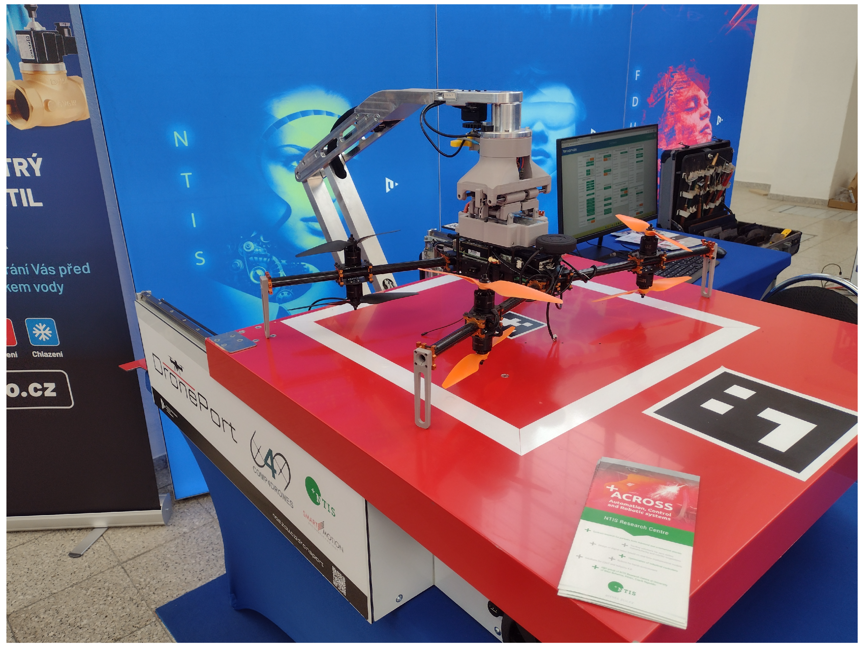
The developed system was designed to enrich the capabilities of drones or drone fleets cooperating together on some missions and requiring a continuous possibility of battery replacement and recharging. Droneport belongs to the family of systems with automatic battery swapping, which is the fastest way to redeploy the drones back to the mission. It was developed for middle-sized drones with batteries placed on top. It can be connected to any UAV with MAVLink communication protocol. The system is now in the phase of validation tests in real operating conditions, covering long-time monitoring, error handling and remote management, safety, etc. The current version of the prototype is depicted in
Figure 18 together with Drone-X8 as a testing UAV from REX Controls company [
37]. A hyperlink to a movie demonstrating the system’s functionality is provided—the reader is referred to
Appendix A.
A comprehensive review of key technical parameters is shown in
Table 1 and
Table 2. We compare the main attributes of our solution with commercially available drone-in-a-box systems. Some manufacturers do not provide the necessary level of detail on their websites or in data sheets. Such entries are marked as N/A (not available) in the tables. It can be seen that our Droneport system is relatively lightweight and compact compared to its peers. It is primarily intended for battery swapping, unlike many systems offering only direct charging of the battery inside of the landed drone. This is perceived as an important advantage diminishing the return to mission time as the drone does not have to wait to complete the charging process. Another important aspect is a limitation to specific drone types in some systems. On the other hand, the Droneport was developed as a general-purpose platform not dependent on specific drones but focused on mainstream battery types. Precision landing support using ArUco markers is also a desirable feature, as it allows a seamless drone approach to the platform. Affordability might be another benefit, with the purchasing costs of our system being around 20 thousand Euros. The compared commercial platforms are offered for prices ranging from 7 thousand to several multiples of our amount. However, a direct comparison is difficult since an exact price is often highly dependent on a specific configuration and additional purchased services such as support, software updates, etc.
The research team plans to focus future development on expanding the functionality of the manipulator with the possibility of payload exchange between the drone and the Droneport. Such possibilities would further expand the area of use of the Droneport system and enrich the capability of existing drones. Please contact the authors if you are interested in using the presented results in your application or research.
Author Contributions
Conceptualization, L.B. and O.S.; methodology, L.B. and O.S.; software, O.S., L.B., T.M. and J.R.; validation, T.M. and L.B.; formal analysis, L.B. and M.G.; investigation, M.G. and O.S.; resources, L.B., O.S. and J.R.; data curating, T.M.; writing—original draft preparation, L.B., O.S. and M.G.; writing—review and editing, M.G.; visualisation, L.B. and O.S.; supervision, L.B.; project administration, O.S.; funding acquisition, O.S. and M.G. All authors have read and agreed to the published version of the manuscript.
Funding
This research was funded by the ECSEL Joint Undertaking (JU) under grant agreement No 826610 (COMP4DRONES) and No 101007311 (IMOCO4.E [
43]) and also from a national project SGS-2022-022 by the University of West Bohemia. The support is gratefully acknowledged.
Institutional Review Board Statement
Not applicable.
Informed Consent Statement
Not applicable.
Data Availability Statement
Supporting data available at links given in the
Appendix A.
Conflicts of Interest
The authors declare no conflict of interest.
Abbreviations
The following abbreviations are used in this manuscript:
| UAV | Unmanned aerial vehicle |
| UAS | Unmanned aerial system |
| DP | Droneport |
| VTOL | Vertical take-off and landing |
| ArUco | Augmented Reality University of Cordoba standard |
| PWM | Pulse-width modeulation |
| HMI | Human-machine interface |
| I/O | Input/output |
| DI | Digital input |
| DO | Digital output |
| CAN | Controller Area Network |
| GCS | Ground control system |
| PC | Personal computer |
| DoF | Degree of freedom |
| CS | Coordinate system |
| HTML | Hypertext markup language |
| USB | Universal serial bus |
| REST | REpresentational State Transfer |
| CSV | Comma separated values |
| FTP | File transfer protocol |
| UDP | User datagram protocol |
| MCM | Motion control manager |
| SFC | Sequential function chart |
| MSV | MSV International Engineering Fair |
Appendix A
Links to Supplementary Materials:
References
- Ayamga, M.; Akaba, S.; Nyaaba, A.A. Multifaceted applicability of drones: A review. Technol. Forecast. Soc. Chang. 2021, 167, 120677. [Google Scholar] [CrossRef]
- Gallacher, D. Drone applications for environmental management in urban spaces: A review. Int. J. Sustain. Land Use Urban Plan. 2016, 3. [Google Scholar] [CrossRef]
- Vergouw, B.; Nagel, H.; Bondt, G.; Custers, B. Drone technology: Types, payloads, applications, frequency spectrum issues and future developments. In The Future of Drone Use: Opportunities and Threats from Ethical and Legal Perspectives; Information Technology and Law Series; T.M.C. Asser Press: The Hague, The Netherlands, 2016; Volume 27, pp. 21–45. [Google Scholar]
- Shahmoradi, J.; Talebi, E.; Roghanchi, P.; Hassanalian, M. A comprehensive review of applications of drone technology in the mining industry. Drones 2020, 4, 34. [Google Scholar] [CrossRef]
- Ahirwar, S.; Swarnkar, R.; Bhukya, S.; Namwade, G. Application of drone in agriculture. Int. J. Curr. Microbiol. Appl. Sci. 2019, 8, 2500–2505. [Google Scholar] [CrossRef]
- Senkans, E.; Kish, B.A.; Wilde, M.; Kimberlin, R.D.; Schaller, R.; Sizoo, D.G.; Kanchwala, T.; Lata, H.; Mangsatabam, R. Flight Tests of Trajectory Energy Management Systems Using a Vertical Takeoff and Landing Vehicle. In Proceedings of the 2021 IEEE Aerospace Conference (50100), Big Sky, MT, USA, 6–13 March 2021; pp. 1–11. [Google Scholar] [CrossRef]
- Williams, A.; Yakimenko, O. Persistent mobile aerial surveillance platform using intelligent battery health management and drone swapping. In Proceedings of the 2018 4th International Conference on Control, Automation and Robotics (ICCAR), Auckland, New Zealand, 20–23 April 2018; pp. 237–246. [Google Scholar] [CrossRef]
- Torabbeigi, M.; Lim, G.J.; Kim, S.J. Drone delivery scheduling optimization considering payload-induced battery consumption rates. J. Intell. Robot. Syst. 2020, 97, 471–487. [Google Scholar] [CrossRef]
- Chen, Y.; Baek, D.; Bocca, A.; Macii, A.; Macii, E.; Poncino, M. A case for a battery-aware model of drone energy consumption. In Proceedings of the 2018 IEEE International Telecommunications Energy Conference (INTELEC), Torino, Italy, 7–11 October 2018; pp. 1–8. [Google Scholar]
- Research and Markets—Insights on the UAV Battery Global Market to 2026-by UAV Type, Battery Type and Geography, 2021. Available online: https://www.globenewswire.com/news-release/2021/08/10/2277719/28124/en/Insights-on-the-UAV-Battery-Global-Market-to-2026-by-UAV-Type-Battery-Type-and-Geography.html (accessed on 26 February 2023).
- Boukoberine, M.N.; Zhou, Z.; Benbouzid, M. Power supply architectures for drones-a review. In Proceedings of the IECON 2019-45th Annual Conference of the IEEE Industrial Electronics Society, Lisbon, Portugal, 14–17 October 2019; Volume 1, pp. 5826–5831. [Google Scholar]
- Dörfler, S.; Walus, S.; Locke, J.; Fotouhi, A.; Auger, D.J.; Shateri, N.; Abendroth, T.; Härtel, P.; Althues, H.; Kaskel, S. Recent progress and emerging application areas for lithium–sulfur battery technology. Energy Technol. 2021, 9, 2000694. [Google Scholar] [CrossRef] [PubMed]
- Malyuta, D.; Brommer, C.; Hentzen, D.; Stastny, T.; Siegwart, R.; Brockers, R. Long-duration fully autonomous operation of rotorcraft unmanned aerial systems for remote-sensing data acquisition. J. Field Robot. 2020, 37, 137–157. [Google Scholar] [CrossRef] [Green Version]
- Wang, Y.; Sun, Q.; Berger, T.; Qi, W. A Drive-through Recharging Strategy for a Quadrotor. In Proceedings of the 2021 IEEE International Conference on Robotics and Automation (ICRA), Xi’an, China, 30 May–5 June 2021; pp. 420–425. [Google Scholar] [CrossRef]
- Cokyasar, T. Optimization of battery swapping infrastructure for e-commerce drone delivery. Comput. Commun. 2021, 168, 146–154. [Google Scholar] [CrossRef]
- Cokyasar, T.; Dong, W.; Jin, M.; Verbas, İ.Ö. Designing a drone delivery network with automated battery swapping machines. Comput. Oper. Res. 2021, 129, 105177. [Google Scholar] [CrossRef]
- Walendziuk, W.; Oldziej, D.; Slowik, M. Power Supply System Analysis for Tethered Drones Application. In Proceedings of the 2020 International Conference Mechatronic Systems and Materials (MSM), Białystok, Poland, 1–3 July 2020; pp. 1–6. [Google Scholar] [CrossRef]
- Kishk, M.; Bader, A.; Alouini, M.S. Aerial Base Station Deployment in 6G Cellular Networks Using Tethered Drones: The Mobility and Endurance Tradeoff. IEEE Veh. Technol. Mag. 2020, 15, 103–111. [Google Scholar] [CrossRef]
- Swieringa, K.A.; Hanson, C.B.; Richardson, J.R.; White, J.D.; Hasan, Z.; Qian, E.; Girard, A. Autonomous battery swapping system for small-scale helicopters. In Proceedings of the 2010 IEEE International Conference on Robotics and Automation, Anchorage, AK, USA, 3–7 May 2010; pp. 3335–3340. [Google Scholar]
- Michini, B.; Toksoz, T.; Redding, J.; Michini, M.; How, J.; Vavrina, M.; Vian, J. Automated Battery Swap and Recharge to Enable Persistent UAV Missions. In Proceedings of the Infotech@Aerospace, St. Louis, Missouri, USA, 29–31 March 2011; American Institute of Aeronautics and Astronautics: Reston, Virigina, 2011; pp. 1–10. [Google Scholar] [CrossRef] [Green Version]
- Ure, N.K.; Chowdhary, G.; Toksoz, T.; How, J.P.; Vavrina, M.A.; Vian, J. An automated battery management system to enable persistent missions with multiple aerial vehicles. IEEE/ASME Trans. Mechatronics 2015, 20, 275–286. [Google Scholar] [CrossRef]
- De Silva, S.C.; Phlernjai, M.; Rianmora, S.; Ratsamee, P. Inverted Docking Station: A Conceptual Design for a Battery-Swapping Platform for Quadrotor UAVs. Drones 2022, 6, 56. [Google Scholar] [CrossRef]
- Liu, Z.N.; Liu, X.Q.; Yang, L.J.; Leo, D.; Zhao, H. An Autonomous Dock and Battery Swapping System for Multirotor UAV. Available online: https://www.researchgate.net/publication/325077351 (accessed on 1 March 2023).
- The Power of Drone Autonomy. Unlocked by FlytNow. Available online: https://flytnow.com (accessed on 26 February 2023).
- AIROBOTICS SOLUTION. Available online: https://www.airoboticsdrones.com (accessed on 26 February 2023).
- DBOX Autonomous Drone Box. Available online: https://dbox.lt (accessed on 22 March 2023).
- DJI Dock. Available online: https://www.dji.com/cz/dock (accessed on 23 March 2023).
- HEISHA Drone Charging Docks. Available online: https://www.heishatech.com/bot-mansion/ (accessed on 22 March 2023).
- Severa, O.; Bouček, Z.; Neduchal, P.; Bláha, L.; Myslivec, T.; Flídr, M. Droneport: From Concept To Simulation. In Proceedings of the System Engineering for constrained embedded systems (DroneSE and RAPIDO ’22), Budapest, Hungary, 21 June 2022; ACM: New York, NY, USA, 2022. [Google Scholar] [CrossRef]
- Bouček, Z.; Neduchal, P.; Flídr, M. DronePort: Smart Drone Battery Management System. In Proceedings of the Interactive Collaborative Robotics, Petersburg, Russia, 7–9 October 2020; Ronzhin, A., Rigoll, G., Meshcheryakov, R., Eds.; Springer International Publishing: Cham, Switzerland, 2021; pp. 14–26. [Google Scholar]
- Bláha, L.; Severa, O.; Barták, P.; Myslivec, T.; Jáger, A.; Reitinger, J. Droneport: From Concept To Prototype. In Proceedings of the 2022 26th International Conference on Methods and Models in Automation and Robotics (MMAR), Międzyzdroje, Poland, 22–25 August 2022; pp. 134–139. [Google Scholar] [CrossRef]
- Švejda, M. New kinetostatic criterion for robot parametric optimization. In Proceedings of the 2017 IEEE 4th International Conference on Soft Computing & Machine Intelligence (ISCMI), Port Louis, Mauritius, 23–24 November 2017; pp. 66–70. [Google Scholar] [CrossRef]
- Avdeev, A.R.; Shvets, A.A.; Torubarov, I.S. Investigation of Kinematics of 3D Printer Print Head Moving Systems. In Proceedings of the 5th International Conference on Industrial Engineering (ICIE 2019), Sochi, Russia, March 2019; Radionov, A.A., Kravchenko, O.A., Guzeev, V.I., Rozhdestvenskiy, Y.V., Eds.; Springer International Publishing: Cham, Switzerland, 2020; pp. 461–471. [Google Scholar]
- REXYGEN Control System. Available online: https://www.rexygen.com (accessed on 26 February 2023).
- PLCOpen Motion Control Standard. Available online: https://plcopen.org/technical-activities/motion-control (accessed on 3 March 2023).
- Goubej, M.; Mertl, J.; Balda, P. Control system design of robotic manipulator for testing of shifting system. In Proceedings of the 2013 International Conference on Process Control (PC), Strbske Pleso, Slovakia, 18–21 June 2013; pp. 241–246. [Google Scholar] [CrossRef]
- Drone-X8. Available online: https://www.rexcontrols.com/drone-x/ (accessed on 26 February 2023).
- HEISHA D50 Drone in a Box. Available online: https://www.heishatech.com/autonomous-drone/d50-autonomous-drone-in-a-box/ (accessed on 22 March 2023).
- HEISHA D80 Drone in a Box. Available online: https://www.heishatech.com/autonomous-drone/d80-drone-charging-dock/ (accessed on 22 March 2023).
- HEISHA D135 Drone in a Box. Available online: https://www.heishatech.com/autonomous-drone/d135-drone-dock/ (accessed on 22 March 2023).
- OPTIMUS Automated Drone Systems. Available online: https://www.airoboticsdrones.com/optimus/ (accessed on 22 March 2023).
- DBX-G7 Drone-in-a-Box System. Available online: https://dbx.h3dynamics.com/ (accessed on 22 March 2023).
- Cech, M.; Beltman, A.; Ozols, K. Digital Twins and AI in Smart Motion Control Applications. In Proceedings of the 27th IEEE International Conference on Emerging Technologies and Factory Automation (ETFA), Stuttgart, Germany, 6–9 September 2022; pp. 1–7. [Google Scholar] [CrossRef]
Figure 1.
Droneport concept sketch and CAD overview.
Figure 1.
Droneport concept sketch and CAD overview.
Figure 2.
H-bot kinematic scheme—assembling location.
Figure 2.
H-bot kinematic scheme—assembling location.
Figure 3.
CAD manipulator model—description of important kinematic parameters.
Figure 3.
CAD manipulator model—description of important kinematic parameters.
Figure 4.
Demonstration of the operational principle—left: folded manipulator inside the Droneport, right: unfolded manipulator above the landed drone.
Figure 4.
Demonstration of the operational principle—left: folded manipulator inside the Droneport, right: unfolded manipulator above the landed drone.
Figure 5.
Overall conception of the Droneport instrumentation—connection of the control computer to the other modules.
Figure 5.
Overall conception of the Droneport instrumentation—connection of the control computer to the other modules.
Figure 6.
Battery case and holder.
Figure 6.
Battery case and holder.
Figure 7.
High current connector overview (left) and temperature sensing during load test (right).
Figure 7.
High current connector overview (left) and temperature sensing during load test (right).
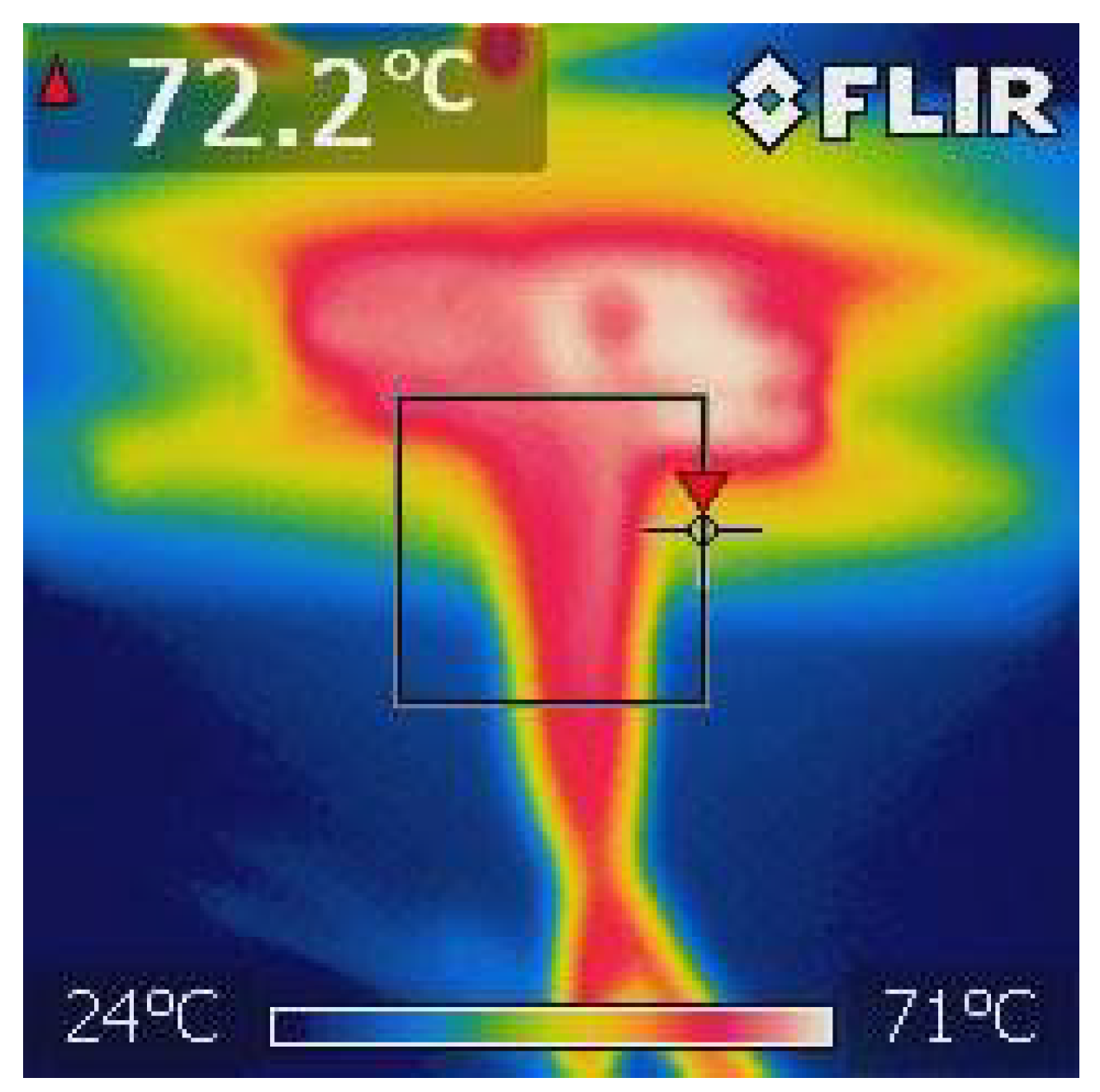
Figure 8.
High current testing: 2D image of temperature load on the high current connector and attached wires shows the heat distribution over their parts and encapsulation.
Figure 8.
High current testing: 2D image of temperature load on the high current connector and attached wires shows the heat distribution over their parts and encapsulation.
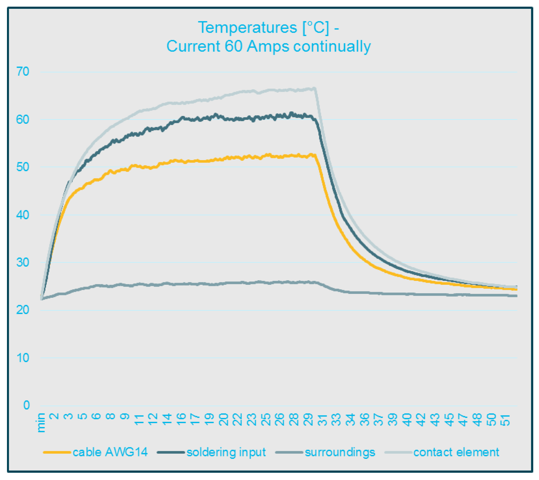
Figure 9.
High current testing: graph of current load and heat dependency with respect to time. It was proved that the connector contacts can continuously transfer the defined current of 60 Amps and the encapsulation, soldering contacts and other elements are exposed to the heat of permissible limits.
Figure 10.
Bottom and side view of the gripper.
Figure 10.
Bottom and side view of the gripper.
Figure 11.
Gripper SW driver block in software REXYGEN and general scheme.
Figure 11.
Gripper SW driver block in software REXYGEN and general scheme.
Figure 12.
Wrapper for image processing.
Figure 12.
Wrapper for image processing.
Figure 13.
Overall control diagram.
Figure 13.
Overall control diagram.
Figure 14.
Functional block diagram: path planning program block and content of simple .JSON configuration file.
Figure 14.
Functional block diagram: path planning program block and content of simple .JSON configuration file.
Figure 15.
Finite automaton for ATMT_node executions with internal SFC.
Figure 15.
Finite automaton for ATMT_node executions with internal SFC.
Figure 16.
Node module example—content of the wait subsystem with SFC.
Figure 16.
Node module example—content of the wait subsystem with SFC.
Figure 17.
HMI for charger monitoring.
Figure 17.
HMI for charger monitoring.
Figure 18.
Current version of the Droneport prototype with the landed drone, exhibited at the MSV International Engineering Fair, Brno Exhibition Centre, Czech Republic.
Figure 18.
Current version of the Droneport prototype with the landed drone, exhibited at the MSV International Engineering Fair, Brno Exhibition Centre, Czech Republic.
Table 1.
Comparison of our solution with existing drone management systems, part I.
Table 1.
Comparison of our solution with existing drone management systems, part I.
| | Droneport | DJI Dock | HEISHA D50 | HEISHA D80 |
|---|
| dimensions [m] | 0.8 × 0.8 × 0.27 | N/A | 0.92 × 0.7 × 0.69 | 1.07 × 0.89 × 0.93 |
| weight | 37 kg | 100 kg | 55 kg | 75 kg |
| IP protection | N/A | IP55 | IP55 | IP54 |
| in the drone charging | no | yes | yes | yes |
| battery swapping | yes | no | no | no |
| outside the drone charging | yes | no | no | no |
| Nr. of battery slots | 4 | 0 | 0 | 0 |
| battery status management | yes | yes | yes | yes |
| battery types | LiIon, LiPo | DJI only (M30) | N/A | N/A |
| weather station | no | yes | yes | yes |
| D-RTK base station | optional | yes | N/A | N/A |
| precision landing support | ArUco markers | N/A | N/A | N/A |
| return to mission/charging time | 2 min. | 25 min. | 40 min. | 45 min. |
| battery compatibility | 2S-6S | DJI M30D, M30TD | 2S-4S | 2S-12S |
| connectivity | Ethernet, wifi, LTE | LTE | Ethernet, 4G | Ethernet, 4G |
| drone type specific | no | yes | no | no |
| source website | | [27] | [38] | [39] |
Table 2.
Comparison of our solution with existing drone management systems, part II.
Table 2.
Comparison of our solution with existing drone management systems, part II.
| | HEISHA D135 | OPTIMUS Airobotics | Dbox M2 | DBX-G7 |
|---|
| dimensions [m] | 1.65 × 1.29 × 1.58 | N/A | N/A | 2.78 × 1.42 × 1.96 |
| weight | 275 kg | 2500 kg | N/A | 450 kg |
| IP protection | IP54 | IP54 | N/A | IP66 |
| in the drone charging | yes | no | N/A | no |
| battery swapping | no | yes | yes | yes |
| outside the drone charging | no | yes | N/A | no |
| Nr. of battery slots | 0 | 11 | 7 | N/A |
| battery status management | yes | yes | N/A | yes |
| battery types | N/A | Airobotics only | N/A | N/A |
| weather station | yes | yes | yes | yes |
| D-RTK base station | N/A | yes | N/A | N/A |
| precision landing support | N/A | yes | ArUco markers | yes |
| return to mission/charging time | 90 min. | N/A | N/A | 40 s. |
| battery compatibility | 6S-12S | N/A | N/A | N/A |
| connectivity | Ethernet, 4G | 5G, LTE, RF | 5G, LTE, RF | 4G, 5G, GMS, LAN |
| drone type specific | no | yes | yes | N/A |
| source website | [40] | [41] | [26] | [42] |
| Disclaimer/Publisher’s Note: The statements, opinions and data contained in all publications are solely those of the individual author(s) and contributor(s) and not of MDPI and/or the editor(s). MDPI and/or the editor(s) disclaim responsibility for any injury to people or property resulting from any ideas, methods, instructions or products referred to in the content. |
© 2023 by the authors. Licensee MDPI, Basel, Switzerland. This article is an open access article distributed under the terms and conditions of the Creative Commons Attribution (CC BY) license (https://creativecommons.org/licenses/by/4.0/).


