1. Introduction
With the rapid development of UAV technology, the multi-UAV network is widely used in civil and military fields such as disaster rescue, air reconnaissance, etc. [
1,
2,
3,
4,
5]. The communication topology of the multi-UAV network affects its work efficiency, and its connectivity can be maintained by controlling the topology of the multi-UAV formation. Therefore, it is fundamental to carry out research on the formation topology control of multi-UAVs. During the actual flight, the limited communication range of UAVs and different environmental factors, such as obstacles and interference sources, will affect the connectivity of the multi-UAV network. Thus, it is necessary to maintain connectivity of the entire multi-UAV network by controlling multi-UAV formations in complex environments [
6].
Scholars at home and abroad have conducted many studies on connectivity maintenance between UAVs. An UAV formation control law was proposed to generate a leader–follower structure based on consistency under the balance of control constraints and communication constraints, so as to avoid collisions and maintain connectivity between UAVs [
7]. The authors in [
8] proposed using the graph coalition formation game to model the cooperation between UAVs, which can quickly restore the required connectivity between UAV networks. In [
9], the connectivity methods were compared in four application scenarios, mainly by increasing or decreasing the communication links between UAVs to increase or decrease the connectivity of UAV clusters. A connectivity tracking algorithm was proposed to track the connectivity distribution over time, and the results are analyzed. The authors in [
10] used the second-order integral characteristic to solve the time-varying formation tracking control problem of multiple UAVs. We consider the correspondence between multi-UAV connectivity and formation control and maintain the connectivity of multi-UAV networks through formation control in complex environments. These papers also consider the problem of UAV formation flight in the case of limited communication. The authors in [
11] studied the formation control problem of multiple agents in the noise environment and transformed the formation control problem into the convergence problem of the infinite product of general random matrix sequences. A flight strategy was proposed to improve the multi-UAV cooperative search ability under the condition of limited resources. A multi-UAV cooperative search model was established. The optimization function of the model considers communication cost and formation benefit to ensure multi-UAV Effectiveness of Human–Machine Search [
12]. A new adaptive formation control method was proposed for UAVs with limited leader information and communication. The method was extended to replace the leader with adjacent UAVs, where the leader can convey location and direction information [
13].
In addition, the formation obstacle avoidance problem of UAVs needs to be considered in the process of formation flight. The aim is the formation and maintenance of a specific configuration to adapt to mission requirements and friendly aircrafts. Currently widely used strategies include the leader–follower method [
14], virtual structure method [
15], behavior-based control method [
16], and the consensus algorithm [
17]. Among them, the algorithm based on consensus theory emphasizes the synchronization, cooperation, and substitutability among individuals. This algorithm meets the characteristics of decentralization, autonomy, and autonomy of UAVs; it thus gradually became the main method and research direction to solve in the formation control of UAVs. In addition, the obstacle avoidance problem of UAVs needs to be considered in the process of formation flight. The artificial potential field (APF) algorithm proposed by Khatib [
18] in 1986 stands out among many obstacle avoidance algorithms because of its simple structure, easy real-time control, and rapid response to environmental changes. An observer-based memory consensus protocol was proposed in [
19] for achieving the consensus of nonlinear multi-agent systems with Markov switching topologies. This approach was applicable for an observer-based nonlinear multi-agent system which was described by switched undirected topologies. In [
20], the authors solved the consensus problem in multi-agent systems with Markov jump, time-varying delay, and uncertainties. In [
21], the authors developed a consistent algorithm to decompose the motion of UAV into three directions, but the constraint processing of instructions in the algorithm convergence process is too cumbersome, which is not conducive to engineering implementation. The authors in [
22] introduced a particle swarm optimization algorithm to deal with static and dynamic obstacles. They added UAV formation configuration requirements to the consensus algorithm. An adaptive distributed control algorithm was proposed to realize the problem of cooperative formation of heterogeneous vertical take-off and landing UAVs under the condition of parameter uncertainty in [
23]. In [
24], the authors developed a novel decentralized adaptive consensus formation control method. Each UAV sets a coordinate and controls its relative position with adjacent UAVs to obtain the desired formation. A multi-UAV formation system based on the leader–follower model was proposed in [
25]. The follower predicts the state of the leader, maintains a relative position in the formation, and finally reaches a consensus with the leader. A topology control algorithm was proposed in [
26] to complete the distributed communication maintenance and formation configuration of four quadrotor UAVs. However, the security requirements for the long-running machine in the cluster are very high.
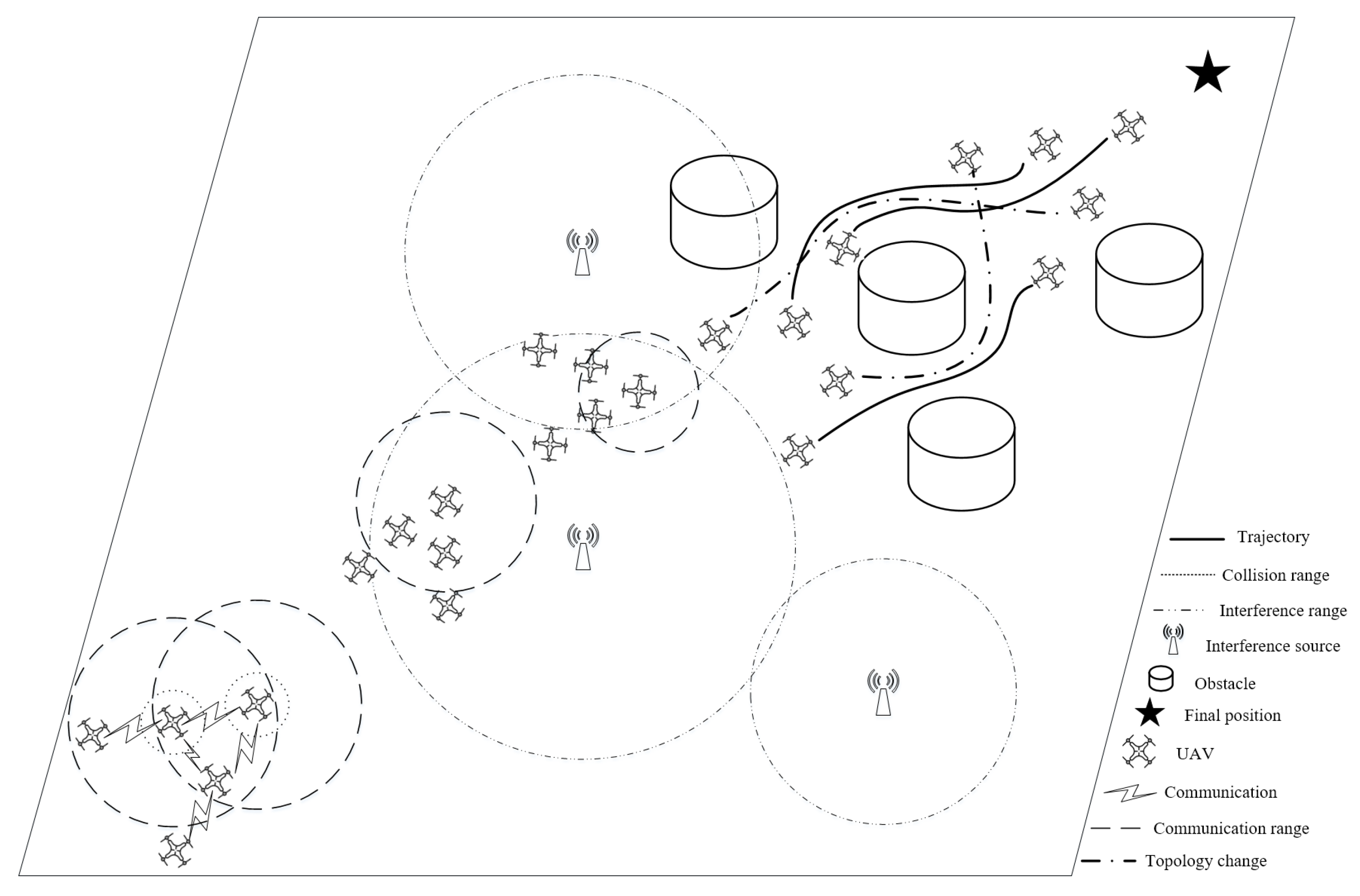
In this paper, aiming at connectivity maintenance of a multi-UAV network and obstacle avoidance of multi-UAV formation, we design a formation control algorithm to overcome the connectivity maintenance and obstacle avoidance problem. The main challenge is to design an excellent formation control algorithm to ensure the connectivity and security of the multi-UAV network during the actual flight due to the limited communication range of UAVs and the existence of different environmental factors, such as obstacles and interference sources. Specifically, the formation switching of the multi-UAV network or the failure of some communication networks will cause the system connectivity to be destroyed. Therefore, the designed formation control algorithm requires the ability to maintain the system connectivity. At the same time, considering the flying speed of a UAV, the designed algorithm requires timely and safe obstacle avoidance. Thus, it is quite necessary to maintain the connectivity of an entire multi-UAV network by controlling multi-UAV formations in complex environments.
This paper proposes a Connectivity-Maintenance UAV Formation Control algorithm, called CMUFC, for the multi-UAV network to complete tasks in complex environments with various obstacles and interference sources. This algorithm considers the communication range and kinematics constraints of UAVs and overcomes the problem of maintaining connectivity when a multi-UAV network is disturbed and avoids obstacles. This paper has the following contributions:
The CMUFC algorithm maintains the connectivity of the multi-UAV network through adaptive scaling formation, and the UAV changes its relative position with other UAVs to maintain the stability of the entire system in the case of interference.
A speed-based artificial potential field (SAPF) algorithm, which helps UAVs avoid obstacles safely in the process of rapid flight, is proposed. Combined with the SAPF and the consensus formation control algorithm, it overcomes the problem of local minimum and solves the problem that APF cannot make UAVs tend to the specified formation.
Aiming at the situation that the formation of a multi-UAV network is forced to change in order to avoid obstacles, a recursive self-repairing formation algorithm based on layering is used to enable the multi-UAV to complete the formation reconstruction and maintain the connectivity of the multi-UAV network.
The rest of this paper is organized as follows.
Section 2 describes the system model.
Section 3 introduces the Connectivity-Maintenance UAV Formation Control algorithm.
Section 4 verifies and analyzes our algorithm. Finally, concluding remarks are provided in
Section 5.
3. Connectivity-Maintenance UAV Formation Control Algorithm
The multi-UAV network maintains connectivity. That is, there is at least one undirected path between every two UAVs, and the communication between adjacent UAVs in this undirected path needs to meet its maximum transmission distance. In areas where there are interference sources, the CMUFC algorithm helps UAVs adaptively change the formation structure to maintain the connectivity of multi-UAV communication topology. In addition, this algorithm combines the SAPF and the consensus formation control algorithm to help the multi-UAV formation to fly to the target position and avoid obstacles, while making the flight distance between the UAVs meet the connectivity requirements.
3.1. Connectivity Maintenance of Multi-UAV Network under Interference
Figure 4 shows the collision zone and communication interaction zone around the UAV, where
is the maximum transmission distance of signals between UAVs,
is the maximum range of influence of obstacles on the UAV, and
is the radius of the UAV. In order to maintain system connectivity, the distance between two adjacent UAVs
in the undirected path cannot be greater than the maximum transmission distance
. In this paper, the effects of interference sources and obstacles on the connectivity of multi-UAV networks are considered.
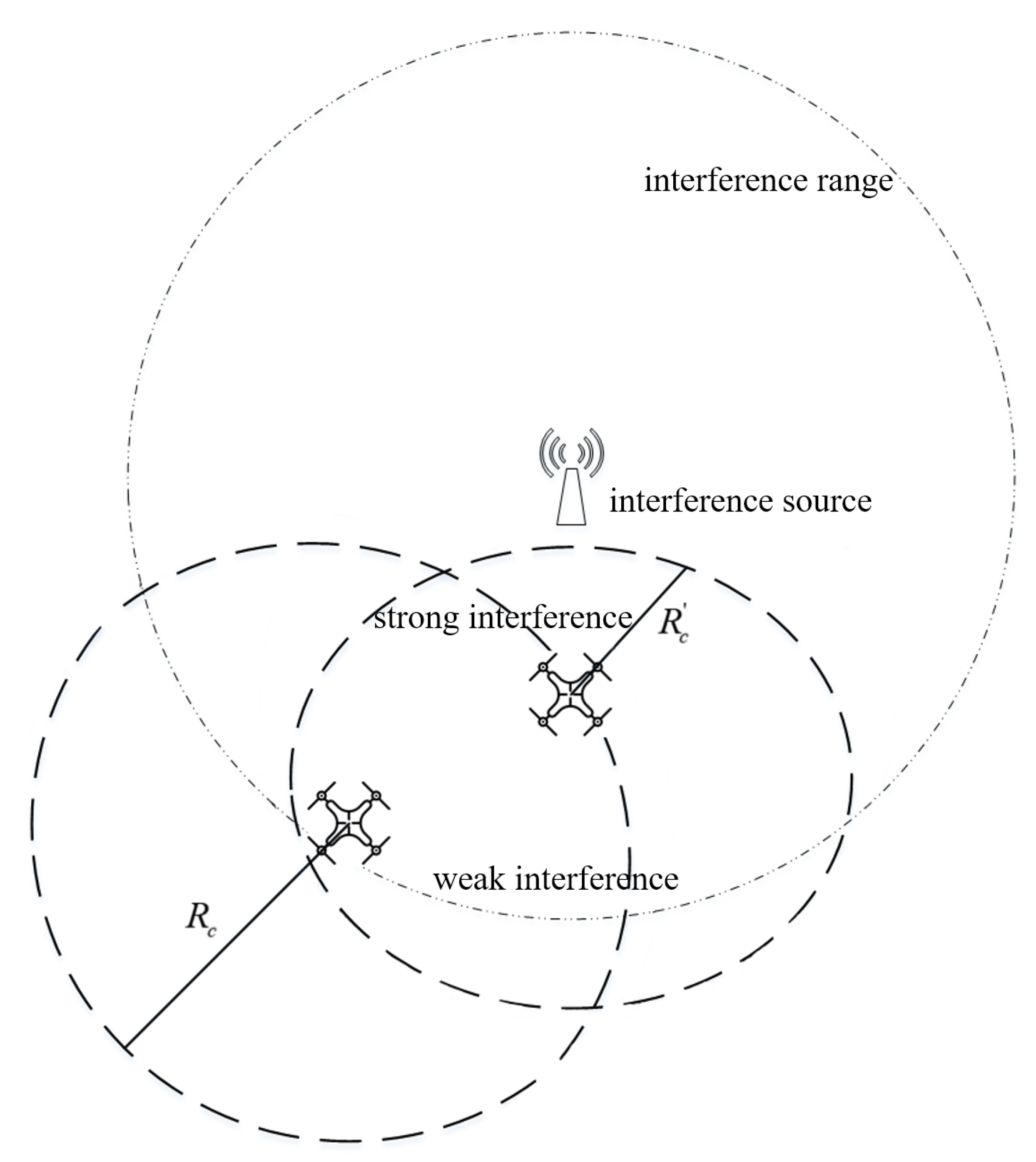
The situation of the interference of a UAV is shown in
Figure 5. When the multi-UAV network is interfered by an interference source, the maximum transmission distance of the UAV signal is reduced. The closer the UAV is to the interference source, the smaller the communication range. This situation reflects the actual UAV formation. That is, the distance between UAVs is scaled adaptively to maintain the connectivity of the system.
3.2. Multi-UAV Formation Control under Obstacle Avoidance
In this paper, the SAPF algorithm and consensus control algorithm are combined to help UAV formation avoid obstacles and keep formation. SAPF is used to help UAVs fly to the target and avoid obstacles, and the consensus control algorithm is used to help multiple UAVs form a specified communication topology. The two algorithms are combined to simultaneously ensure that no collision occurs between UAVs and communication interaction can be maintained. That is,
The SAPF algorithm establishes an attractive potential field for the target and a repulsive potential field for the obstacle. The two potential fields are combined to avoid the collision between the UAV and the obstacle in the process of flying to the target position. The attractive and repulsive potential fields are expressed as
where
is the attraction gain factor,
is the repulsive force gain coefficient,
denotes the vector distance between UAV and target position,
is the vector distance between the UAV and the obstacle, i.e., the Euclidean distance between two points.
is a constant that represents the maximum range over which the obstacle can affect the UAV. The attractive and repulsive forces are the negative gradients of the attractive and repulsive potential fields, respectively, and the attractive and repulsive force functions are expressed as
Then, adding the speed steering force to solve the local minimum problem, the speed steering force is expressed as
where
is the speed repulsion force gain coefficient,
v is the speed of the UAV, and the direction of
is perpendicular to
v. Therefore, the resultant repulsive force is expressed as
In addition, this paper adopts the formation control mode of the virtual pilot. Then, the consensus algorithm, according to the double integral dynamic system shown in Equation (2), is further expressed as
where
and
are stiffness gains,
and
are damping gains,
represents the adjacency matrix of each UAV communication topology in a multi-UAV network, and
is the relative position of UAV
i and UAV
j.
and
are the speed and position of the virtual leader. That is,
represents the tracking item of the virtual leader by the UAV.
Therefore, based on the SAPF generated forces derived from each UAV’s current position and speed and environmental conditions, combined with the control inputs generated by the consensus control algorithm, the control inputs for UAV
i in the multi-UAV network are as follows
where
is the mass of UAV
i. In summary, the formation control algorithm of multi-UAV network controls the flight direction and speed of UAV
i by controlling the input
to solve the obstacle avoidance problem of multi-UAV network.
3.3. Formation and Connectivity Restoration of Multi-UAV Network
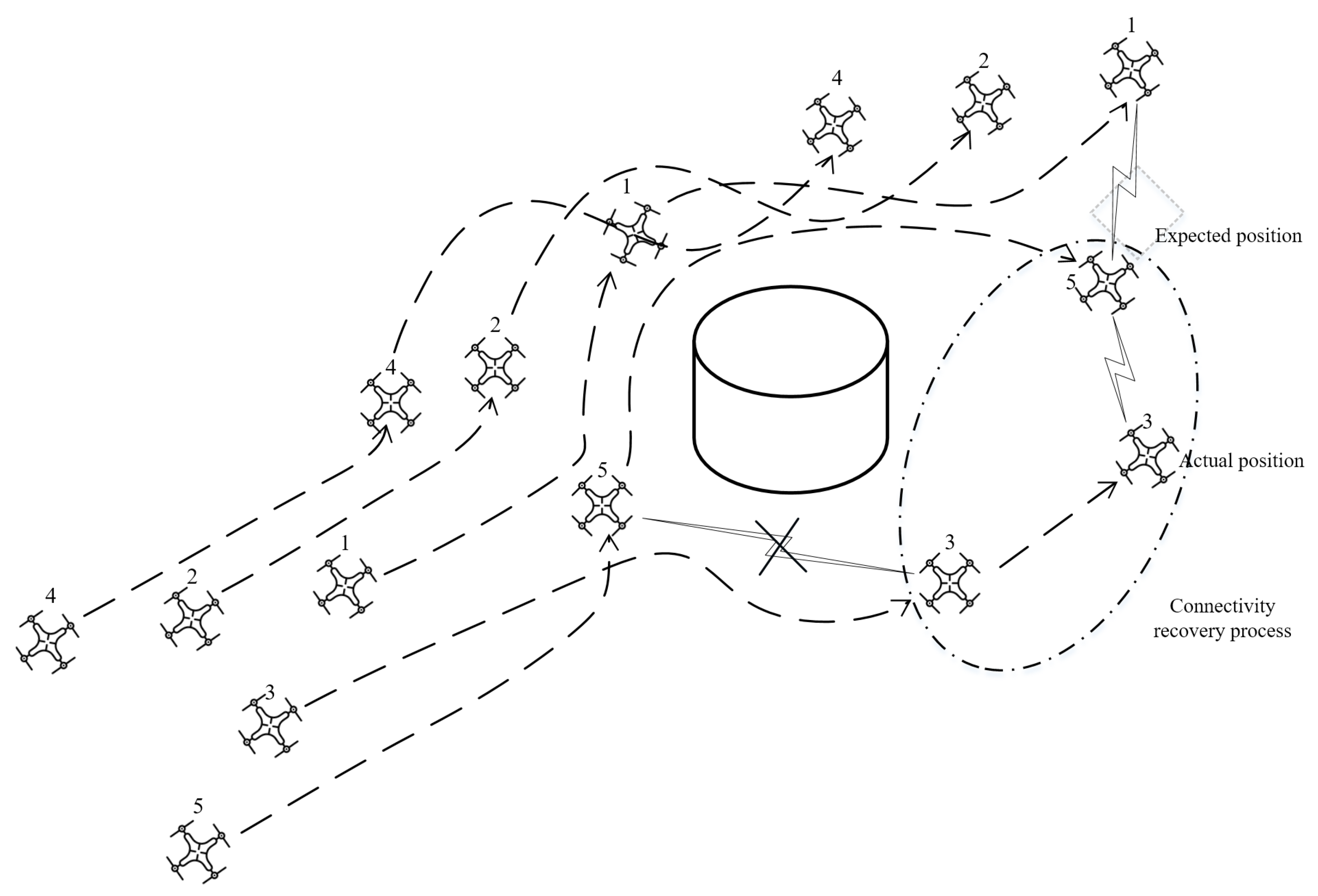
As shown in
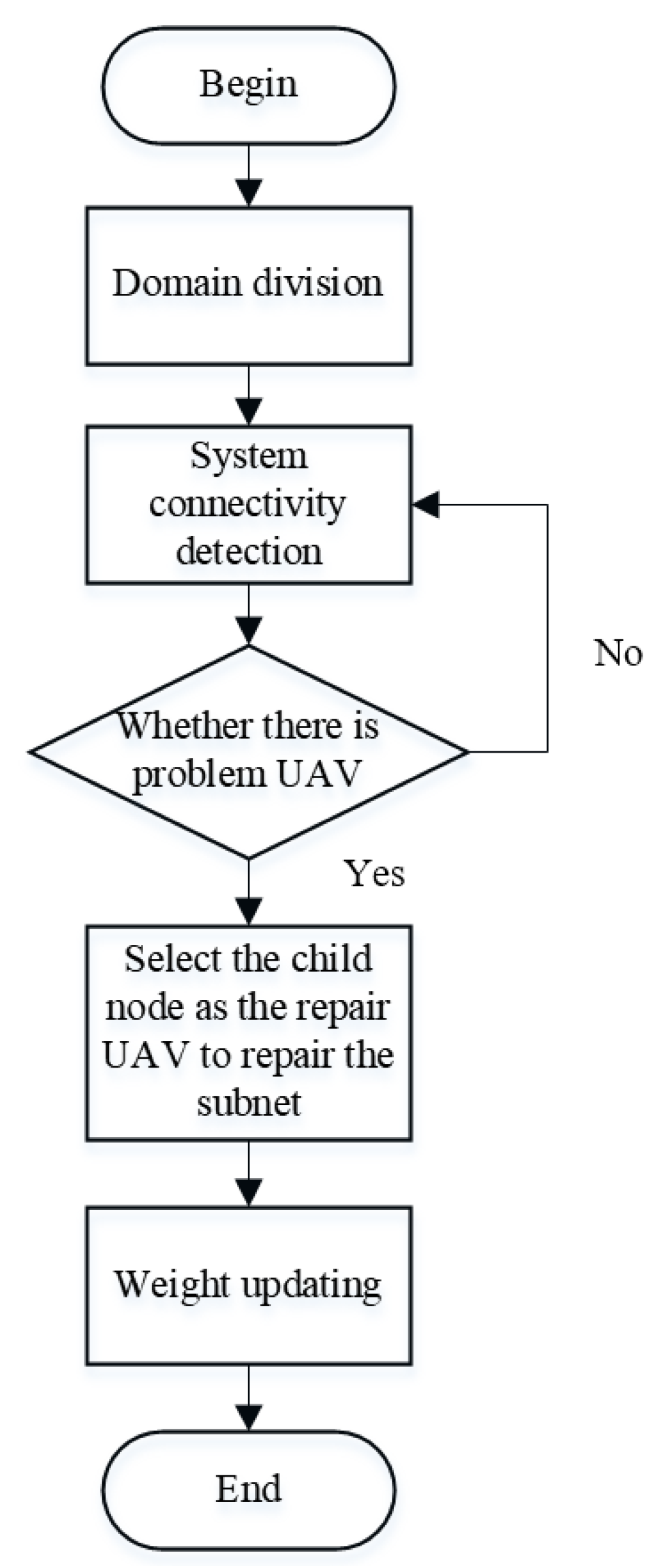
Figure 6, UAVs move away from the formation in order to avoid obstacles during flight. UAV 3 loses connection with the formation to avoid obstacles, and UAV 5 restores connectivity to the multi-UAV network as a repair UAV. In this paper, a layer-based recursive self-healing formation algorithm is used for the situation that a multi-UAV network cannot maintain connectivity when UAVs have to stay away from the system in order to avoid obstacles during flight. When the topology of multi-UAV network formation is forced to change, the algorithm can maintain the connectivity of the system network and complete formation reconstruction without changing the network topology relationship of UAVs. The proposed algorithm block diagram is shown in
Figure 7.
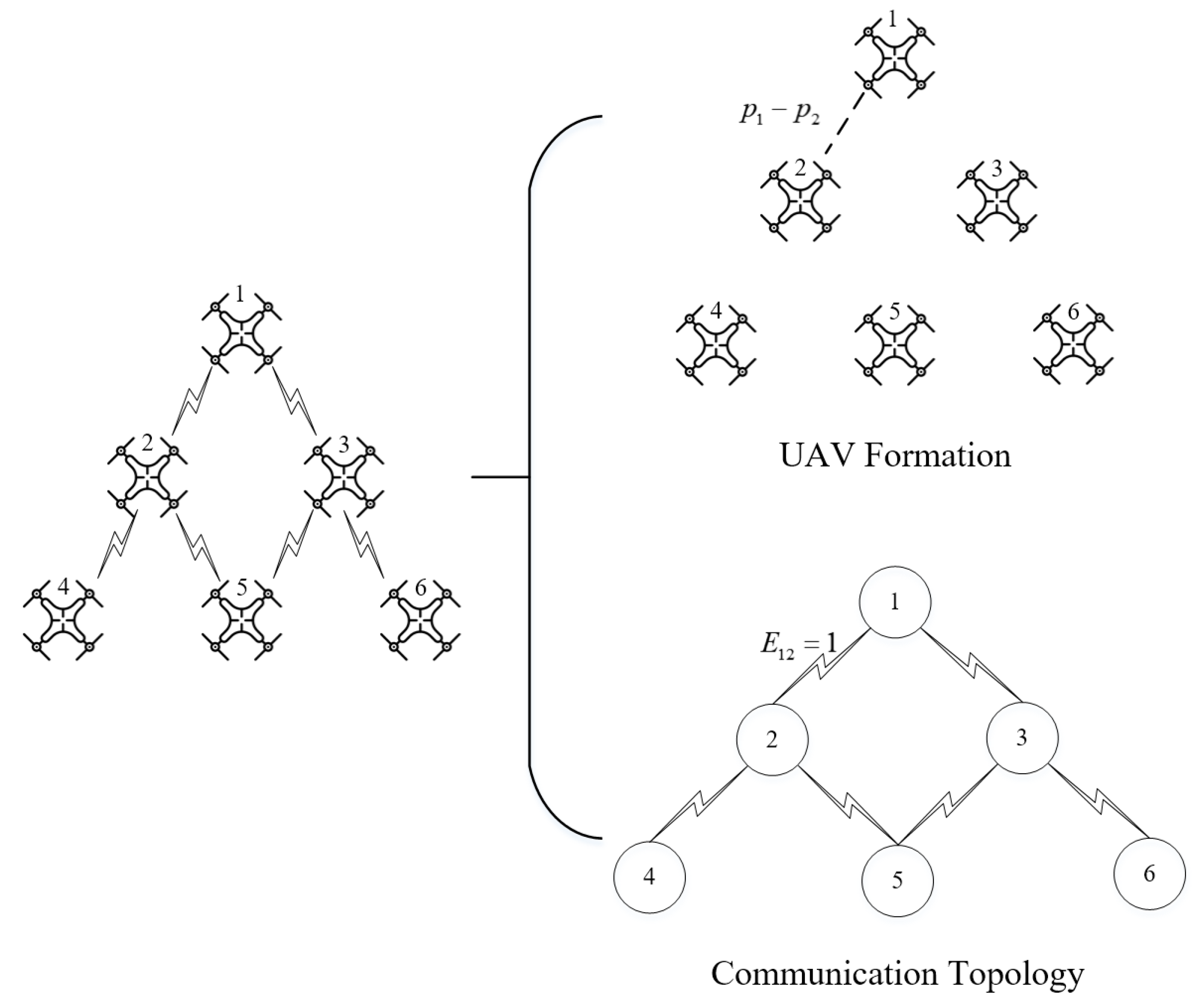
Before the departure of the multi-UAV network, UAVs are divided into layers according to the number of communication links of them. If there is a communication link between UAV i and UAV j, then . Select UAV i, satisfying , as the first layer of the multi-UAV network. If there are UAVs with the same number of links, select the UAV close to the target position. Then, the UAVs that have a communication link with the UAVs on the first layer are used as the second layer, and the division method of the third layer and subsequent layers is the same as above. Then, number each UAV in order from top to bottom and from left to right and assign weights to UAVs according to the position difference of each UAV in the expected formation. Generally, the multi-UAV expected formation is divided into three layers from top to bottom according to the principle of hierarchical division, and the basic formation configuration is obtained. The position of the first UAV in the initial formation is generally at the center UAV of the first layer. The numbering method of the second layer specifies the relative position of each UAV in order from left to right. The naming method of the third layer and subsequent layers is the same as that of the second layer. After layering, two control mechanisms, hierarchical weight and intra-layer position weight , were established by setting the corresponding weight coefficients to ensure the stability of the UAV reconstruction formation. The UAVs in the first layer have the largest , which decrease according to the increase of the number of layers; the position weights within the layer decrease in order from left to right. For V-shaped formations, each UAV within the same layer is equal, is not equal, and .
When a UAV is damaged or forced to leave the system, the child UAV of the problem UAV is used as the repair UAV. The multi-UAV formation is traversed down along the communication link until the entire UAV formation is traversed. Then, the repair subnet is established. If there are multiple child UAVs, the child UAV that can reach the expected position of the problem UAV the fastest is judged as the repair UAV according to the position, speed, and acceleration of each child UAV at the current moment. If there are multiple problematic UAVs, select the child UAV of the problematic UAV with a larger weight to repair the missing position. The repair UAV first flies to the desired position of the problem UAV, so as to establish connectivity with other child UAVs of the original problem UAV. The repair UAV is within the maximum communication link range with the root UAV of the problem UAV and approaches the movement direction of the problem UAV when it leaves the team. It then restores the connection with the problem UAV as much as possible. If the connection with the problem UAV cannot be restored, the sub-UAV of the repair also approaches the problem UAV to form a serial link to expand the communication range.
After the repair subnetwork is established, the weights of the sub-UAVs of the problem UAVs are updated. First, each UAV recalculates the current weights according to the formation in the repair subnetwork. It then sends the new weights to the UAVs through the link. Human–machine and the repair UAV sums the new weight and its own weight to realize the weight update.
3.4. Connectivity-Maintenance Formation Control Algorithm
Algorithm 1 shows the pseudocode of the CMUFC algorithm. First, initialize the position of
M UAVs in the multi-UAV network, as well as the radius, maximum speed, acceleration and other parameters of the UAVs. Randomly initialize the positions of
O obstacles and
K interference sources. Set the transmit power of interference sources, the influence range of obstacles, etc. (lines 1–2). Let
denote the mission completion time of UAV
i, where
. Divide each task duration
in the discrete time domain into multiple time steps
t according to a fixed time interval
. That is,
t is represented as the
t-th time period
. Second, at each time slot
t, for each UAV
i, first calculate the communication distance according to the interference power and path loss of the interference source. Then, calculate the distance between it and other UAVs with communication links in the system. Calculate the distance between it and the target position and obstacle position. After that, calculate the resultant force generated by the multi-UAV formation obstacle avoidance control algorithm according to the distance. Finally, calculate the position of the UAV under the constraints of speed and acceleration at time
(lines 5–8). Third, judge whether there is an undirected path in the multi-UAV network at time
to satisfy the system connectivity. If it exists, continue looping. If it does not exist according to the CMUFC algorithm, the problem UAV is set as the root UAV, and its child UAVs are used as the repair UAV. Then, let it fly to the expected position to restore system connectivity (lines 9–13).
| Algorithm 1 CMUFC |
- 1:
Initialize the physical parameters of M UAVs - 2:
Initialize the physical parameters of O obstacles and K interference sources - 3:
for do - 4:
for do - 5:
Calculate the communication distance of UAV i in Equation ( 10) - 6:
Calculate the distance between UAV i and neighboring UAVs in the undirected path - 7:
Calculate the resultant force of UAV i in Equation ( 20) - 8:
Calculate the position of UAV i under the constraints at time - 9:
if there is an undirected path in the multi-UAV network then - 10:
Continue the cycle - 11:
else - 12:
Repair system connectivity - 13:
end if - 14:
end for - 15:
end for
|
4. Simulation Results
In this section, we simulate a V-formation multi-UAV network and analyze the simulation results. The relevant parameters of the simulation are shown in
Table 1.
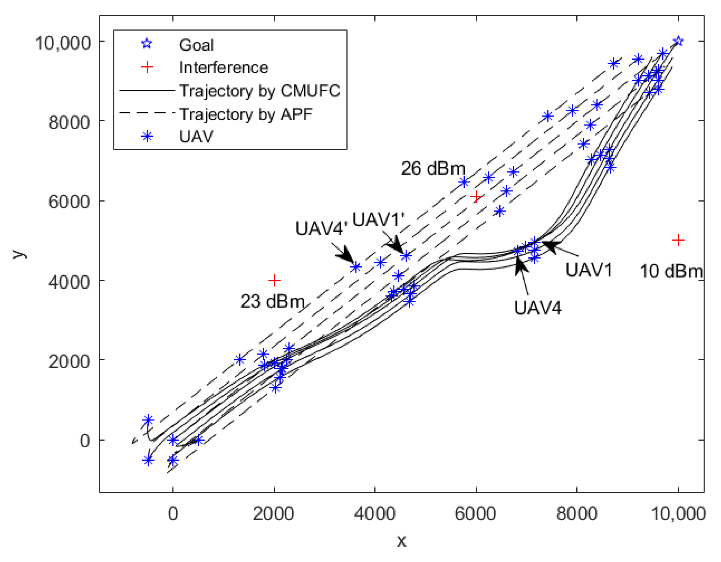
We simulate the performance of the CMUFC algorithm in different scenarios and compare it with the traditional formation control algorithm by APF. The scenario where there are interference sources is shown in
Figure 8, and the powers of these three interference sources are 23 dBm, 26 dBm, and 10 dBm, respectively. The CMUFC algorithm helps UAVs to fly to areas with less interference, thereby maintaining the connectivity of the multi-UAV network.
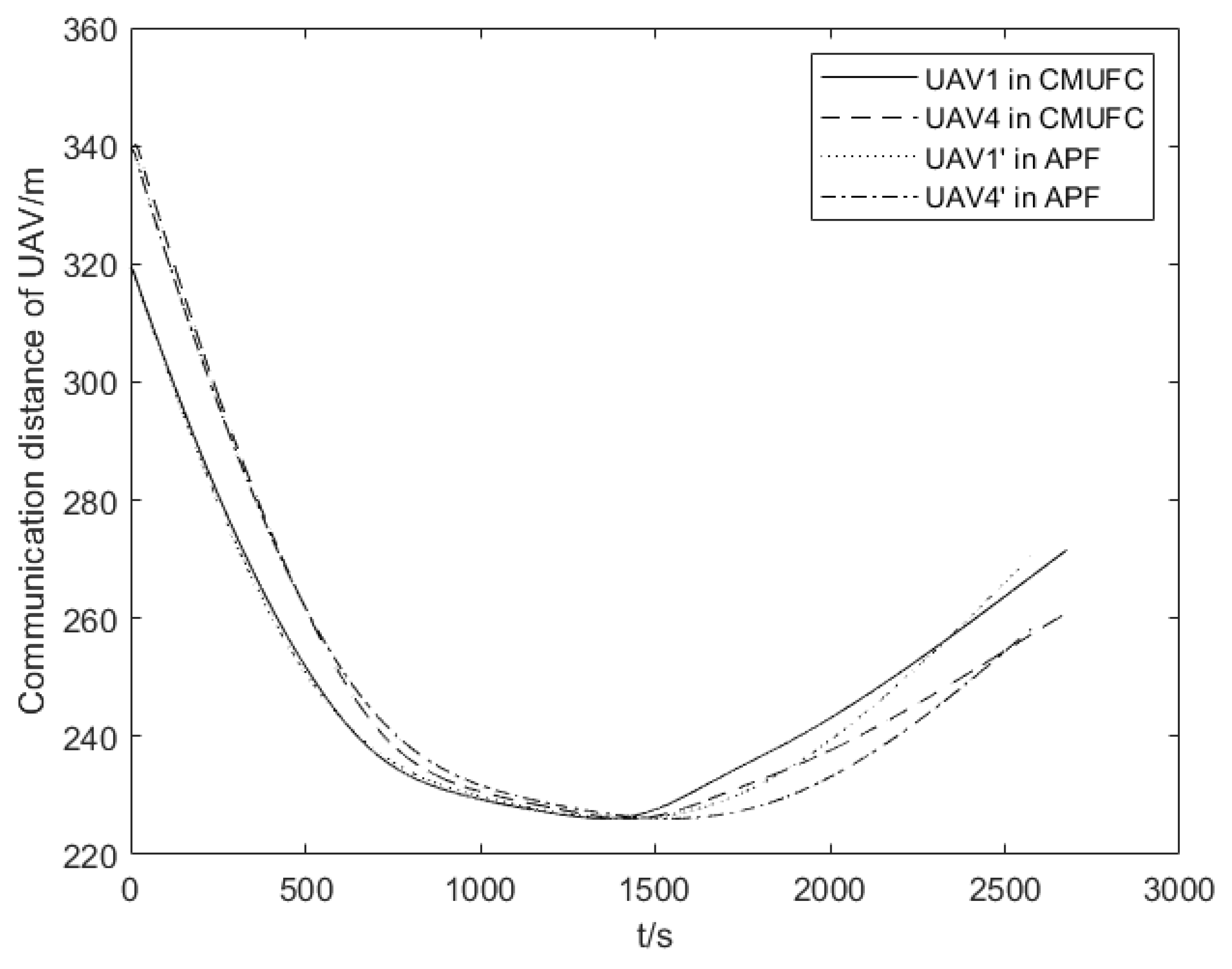
Figure 9 shows the communication range of UAVs. When the multi-UAV network is closer to the interference source, the communication range is smaller. Among them, UAV1 and UAV4 are the UAV communication ranges calculated by our proposed algorithm, and UAV
and UAV
are the communication ranges calculated by the traditional formation control algorithm.
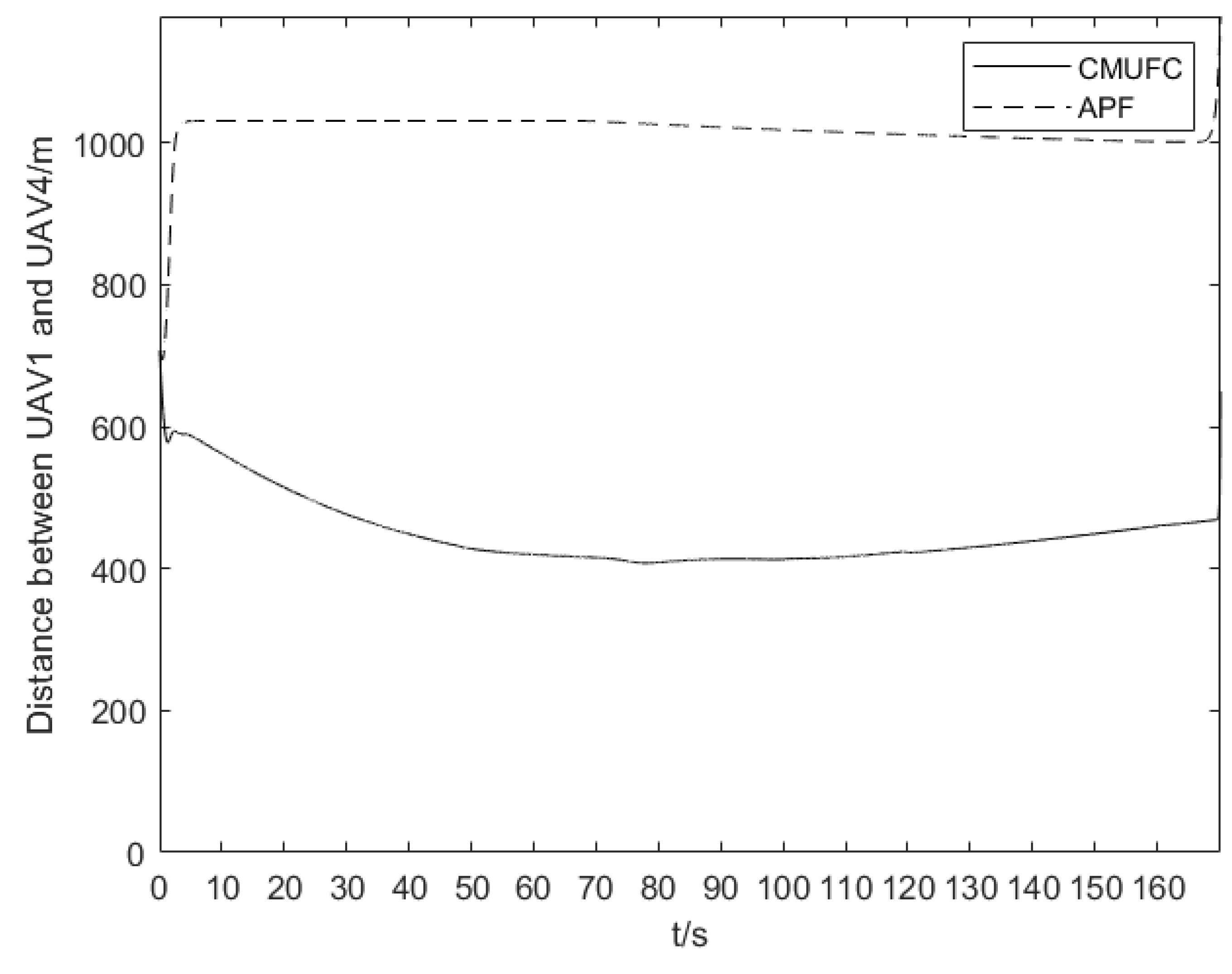
Figure 10 shows the distance between two UAVs. The proposed algorithm can help the multi-UAV network adaptively reduce the formation distance to maintain the connectivity of the entire network when the communication range decreases. In addition, as shown in
Figure 10, the farthest distance between two UAVs in the multi-UAV network, UAV1 and UAV4, satisfies the communication requirements of UAVs shown in
Figure 9. However, the traditional formation control algorithm makes the distance between UAVs far greater than its communication distance, resulting in the inability of the multi-UAV network to maintain connectivity.
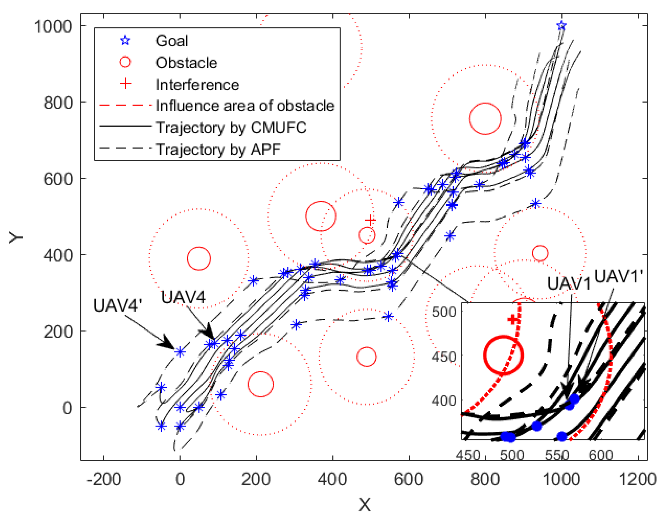
Furthermore, we simulate a complex environment with obstacles and interference sources as shown in
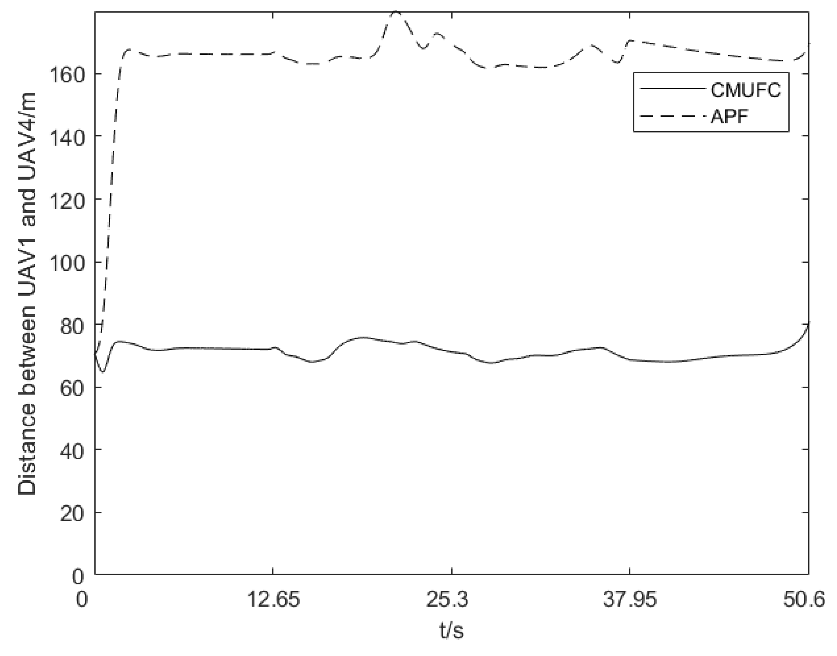
Figure 11, where the power of the interference source is 36 dBm, and the radius of the obstacle is 30–50 m. The CMUFC algorithm helps the multi-UAV network fly away from the interference source to maintain connectivity. Due to the existence of interference, the communication distance between UAVs is reduced, making it easier for UAVs to collide with obstacles. Compared with the traditional formation control algorithm, our algorithm keeps the multi-UAV network away from obstacles and improves safety. The distance between UAV1 and UAV4 when flying in a complex environment is shown in
Figure 12. The CMUFC algorithm helps UAVs shorten the distance between them without colliding with each other to maintain the connectivity of the entire system when UAVs are interfered.
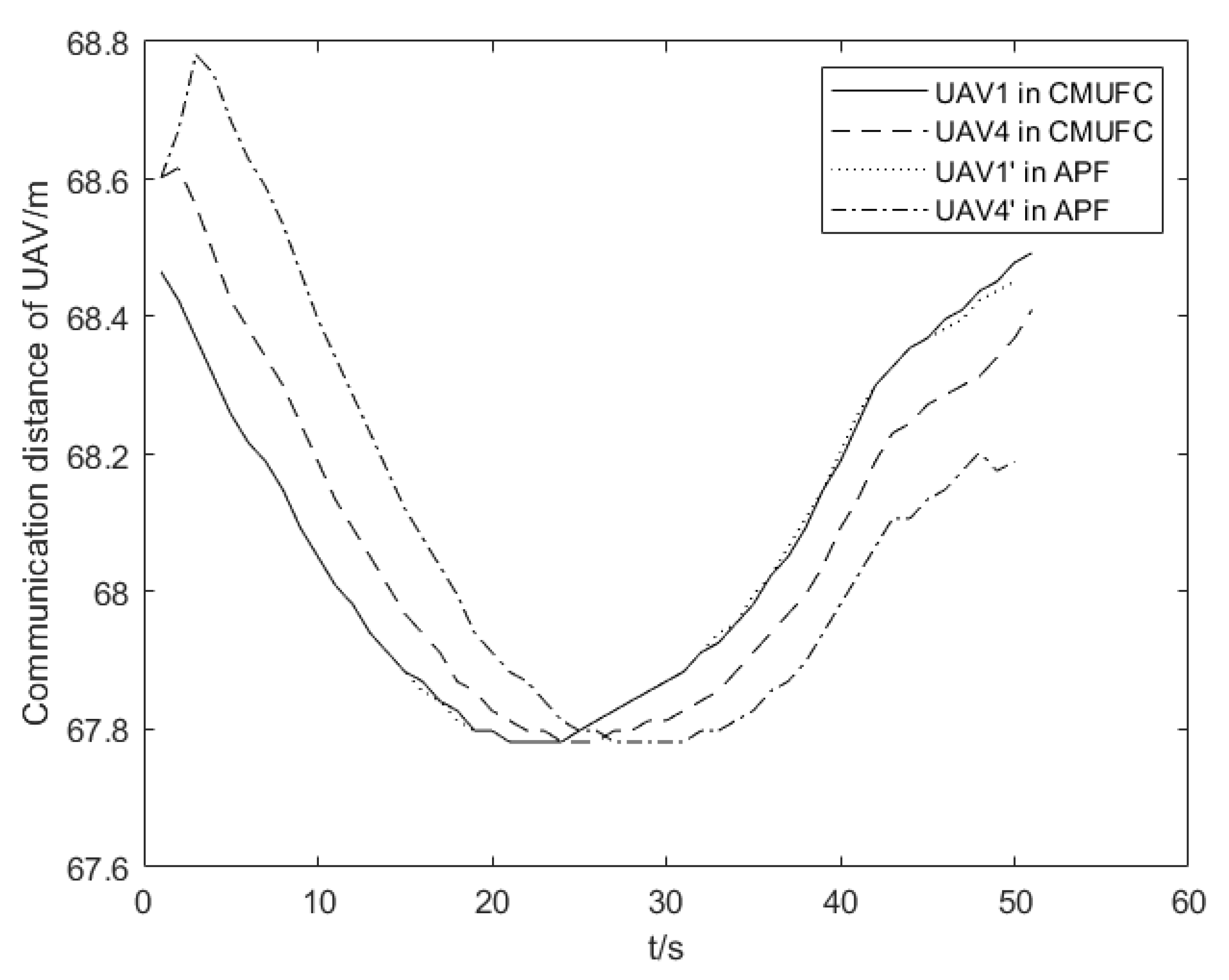
Figure 13 shows the communication distance of UAVs in complex environments. Compared with the traditional formation control algorithm, the CMUCF algorithm controls the flight distance between the UAVs to be less than its communication distance in their entire flight.


