Article

Real-Time Positioning Method for UAVs in Complex Structural Health Monitoring Scenarios

1
School of Civil Engineering, Architecture and Environment, Hubei University of Technology, Wuhan 430068, China
2
Innovation Demonstration Base of Ecological Environment Geotechnical and Ecological Restoration of Rivers and Lakes, Wuhan 430068, China
3
Guangzhou Metro Design and Research Institute, Guangzhou 510010, China
*
Author to whom correspondence should be addressed.
Drones 2023, 7(3), 212; https://doi.org/10.3390/drones7030212
Submission received: 26 February 2023 / Revised: 16 March 2023 / Accepted: 18 March 2023 / Published: 19 March 2023

Abstract

:
UAVs are becoming increasingly used in the field of structural health monitoring, and the position information of them during the tasks is crucial. However, in complex scenarios such as bridges and high-rise buildings, the GNSS positioning method cannot obtain the positions of the UAV all the time due to the blockage of satellite signals and multi-path effects. This paper proposes a real-time positioning method to address the issue combining GNSS and total station. The GNSS is first used to locate the UAV when it is not in the line of sight of the total station, and the coordinates of the UAV are transmitted to the total station for blind tracking through coordinates conversion. The total station is then used to directly track the UAV when it flies to the GNSS-denied area and appears in the field view of the total station. Experiments show that the shift from blind tracking to direct tracking can be guaranteed as the coordinates conversion error is always less than the field of view range of the total station, even if only two common points are used for coordinates conversion. In addition, high positioning accuracy can be achieved in complex structural health monitoring scenarios.

1. Introduction

Civil infrastructures, which include bridges and buildings, play an important role in human life, and the safety of them cannot be ignored during long periods of operation. It is necessary to conduct structural health monitoring [1,2,3] to ensure safety and avoid unnecessary losses. With the improvement of modern construction technologies, structures become increasingly complex, and more of them are built in difficult areas, resulting in the shortcomings of traditional structural health monitoring methods, such as low efficiency and insufficient safety. Unmanned aerial vehicles (UAVs), with the advantages of small size and light weight, being highly maneuverable and flexible, are suitable for structural health monitoring for complex structures. Many researchers have already used them for such purposes [4,5]. Structural health monitoring with UAVs functions in the way of detecting defects such as cracks, spalling, and water seepage by taking pictures. It is important to determine the positions of defects for further maintenance. Generally, the positions of the above-mentioned defects are located by determining the positions of the UAV when taking images. For the UAV positioning method, the global navigation satellite system (GNSS) is most used outdoors [6,7,8,9]. With real-time kinematic (RTK) technology, it can achieve centimeter-level positioning accuracy. Unfortunately, in places such as three-dimensional traffic constructions, bridges, and high-rise buildings, satellite signal blockages and multi-path effects bring challenges to UAV positioning with GNSS. In order to overcome the above problems, positioning technologies such as Wi-Fi [10,11], ultra-wideband (UWB) [12,13,14,15], and ultrasound [16,17] are applied to determine the position of the UAV. Aiming at flexible and convenient monitoring with UAVs, Han et al. [18] proposed an image-based detection and location method for cracks on the surface and to avoid potential safety accidents. Li et al. [10] proposed a set of UAV positioning methods for indoor environments based on the integration of Wi-Fi and IMU. Based on the advantages of the ranging accuracy and the refresh frequency of UWB, Li et al. [12] proposed the application of UWB to the relative positioning of UAVs. Son et al. [19] proposed a method to calculate the optimal volume of waste storage in environmental management by combining terrestrial laser scanners and UAV positioning. Aytaç et al. [17] utilized the ultrasonic sensor installed on the UAV to filter the relevant location information of the mine to obtain a more accurate map of the mine and improve the work efficiency of miners. Vision technology and airborne cameras have been used for UAV positioning [20,21,22], and a set of vision-based algorithms, including deep learning, have been adopted. Experimental results show that these methods can provide reliable real-time positioning.
A single method cannot meet the needs of real-time positioning of UAVs in complex scenes, such as across high-rise buildings and at the bottom of bridges. In addition, the combination of positioning methods to achieve real-time positioning for UAVs have been studied. Li et al. [23] proposed a UAV positioning method based on GNSS, inertial navigation system (INS), and visible light sensor fusion. Li et al. [13] proposed an indoor navigation and positioning method for UAVs that integrates information from three-dimensional laser scanners, UWB, and INS. The total station can achieve millimeter-level positioning accuracy and track the target automatically [24,25], making it an alternative method for UAV positioning in complex structural health monitoring scenarios. In addition, tracking UAVs or other moving objects with total stations has been tested [26,27]. Ishii et al. [28] proposed autonomous UAV flight using the total station to estimate self-localization in a non-GNSS environment. Benjumea et al. [29] proposed a localization system for UAVs in inspection tasks with a robotic total station in the absence of a GNSS signal. However, the UAV may fly out of the field view of the total station in complex structure scenarios, making the total station unable to track the UAV. In this paper, we propose a real-time positioning method for UAVs, combining total station and GNSS, when it is used for structural health monitoring in complex scenarios. Firstly, the conversion parameters for the coordinate systems of GNSS and the total station are obtained with common points. When the UAV is not in the field view of the total station, the coordinates of the UAV are obtained through GNSS and transmitted to the total station so that it can blindly track the UAV through coordinates conversion. When the UAV flies to a GNSS-denied area and appears in the field view of the total station, the blind tracking mode of the total station is shifted to direct tracking and the coordinates of the UAV can be obtained with it. The structure of this article is organized as follows. Section 2 introduces the positioning principles of GNSS and the total station. And the principle of the proposed real-time positioning method is also described. The effectiveness and accuracy of the proposed method are verified with experiments and field tests in Section 3. Section 4 summarizes the main conclusions and research prospects.

2. Methods

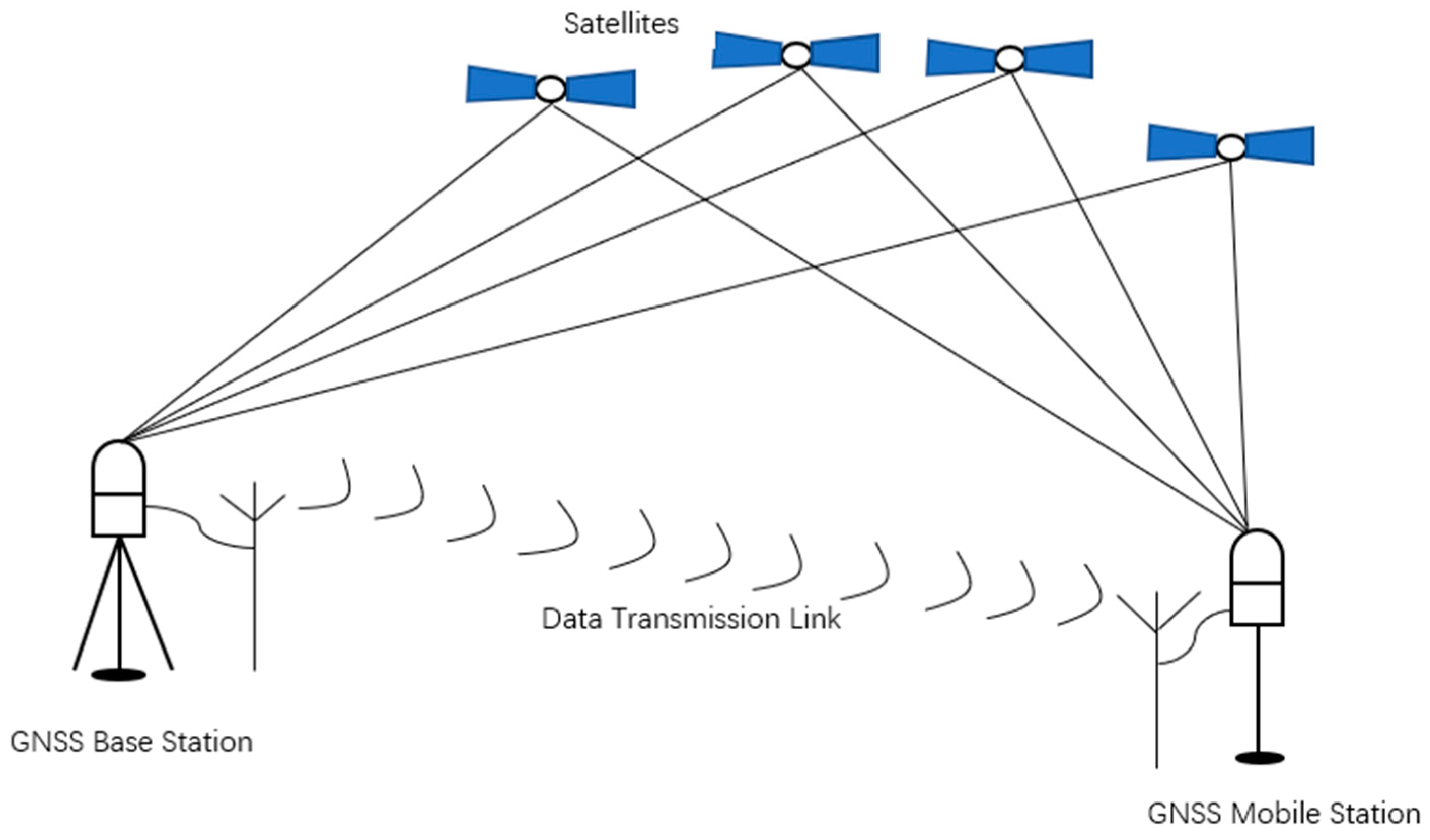
2.1. Real-Time Kinematic Positioning

Real-time kinematic (RTK) is a positioning technology based on GNSS carrier phase difference measurements, and it combines wireless data transmission to achieve real-time dynamic centimeter-level positioning. As shown in Figure 1, RTK positioning technology usually includes four parts: satellites, base stations, a mobile station, and a data transmission link between the two stations. The principle of RTK positioning is that the satellite receiver on the base station and the mobile station simultaneously receive signals from multiple satellites, and, at the same time, the base station sends the received satellite measurements and known station coordinates to the mobile station through the data transmission link. The mobile station determines its position through differential processing between the measurements of the base station and its own position.
With the development of science and technology, the network RTK positioning technology appeared. At present, the advanced representative of the network RTK positioning technology is the continuous operation reference station system (CORS). When using the CORS system, the user does not need to set up a GNSS base station, and can achieve centimeter-level positioning accuracy through the differential service provided by the control center of CORS through the wireless network, such as 4G, which has advantages over the single base station method.
RTK positioning has the advantages of all-weather automatic real-time positioning, high positioning efficiency, fast speed, and simple operation. However, it cannot be used for indoor positioning, as satellite signals cannot penetrate, and its accuracy is affected by tropospheric and multipath effects.

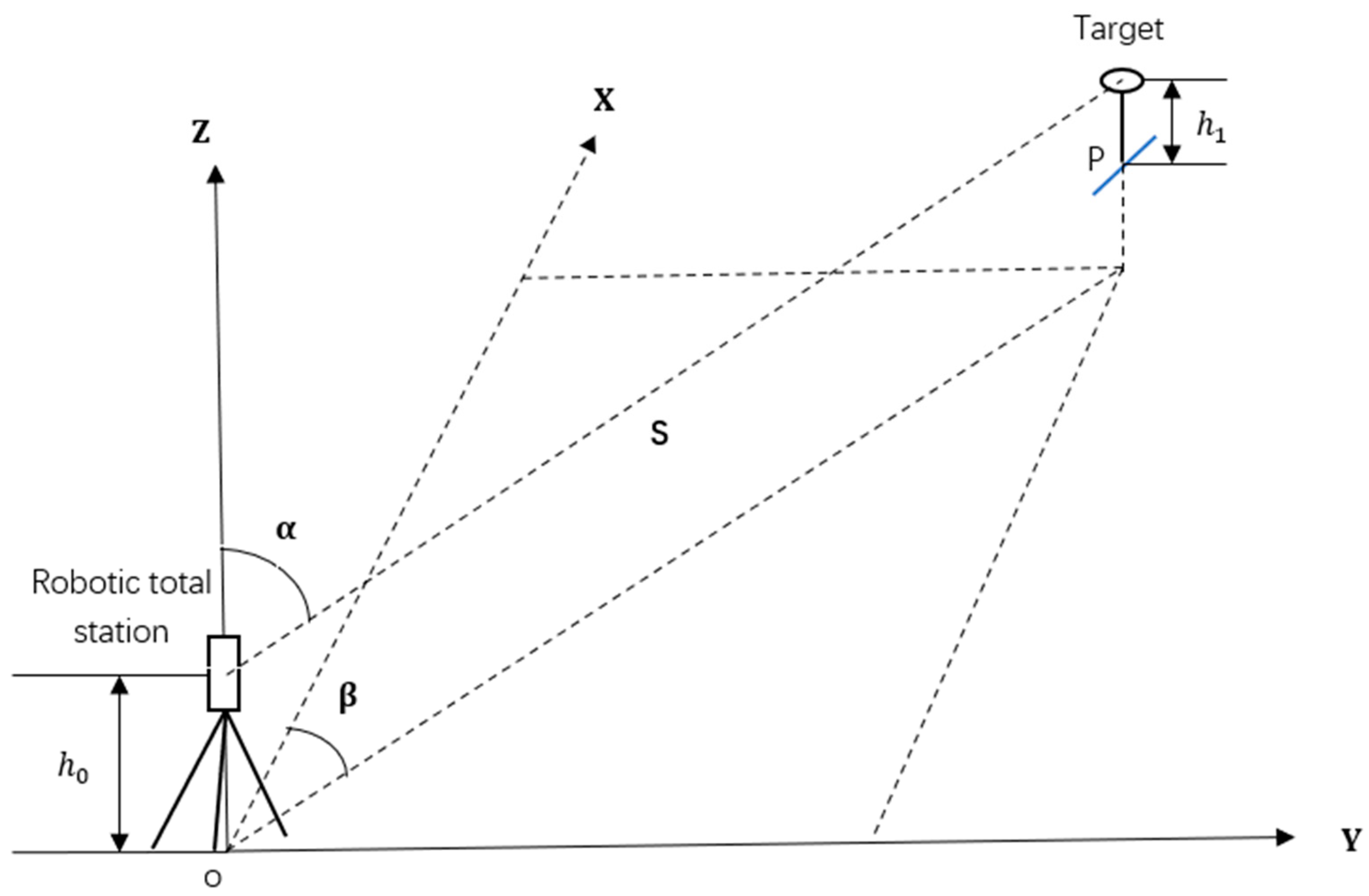
2.2. Total Station Based Positioning

The total station is a typical surveying instrument that integrates the functions of ranging and angle measuring. Taking the prism as the target, the total station can also be used for positioning. The principle is shown in Figure 2. First, set up the total station at the station point with known coordinates ( x 0 , y 0 , z 0 ), then, aiming at the prism, the slope distance S , vertical angle α , and horizontal angle β can be obtained. The coordinates of the prism ( x 1 , y 1 , z 1 ) can be calculated as follows:
x 1 = x 0 + S sin α cos β y 1 = y 0 + S sin α sin β z 1 = z 0 + h 0 + S cos α h 1
where h 0 is the instrument height; h 1 is the prism height.
A variety of sensors have been integrated into the total station, which makes it more automated and intelligent. Two of these integrations are particularly important: one is the image sensor, and the other is the servo motor. The image sensor is used to realize automatic target recognition (ATR), and the servo motor can drive the total station to rotate automatically. Based on the above functions, the total station can automatically lock and track the target to achieve real-time positioning with a range of up to 1000 m, taking the Leica TS60 total station as an example.
When the total station performs positioning and tracking, its measurement accuracy can reach the millimeter level, and it has the advantages of low manual intervention and strong terrain adaptability. The main disadvantage is that the total station must be in line of sight with the target. If it encounters obstacles, it will lose track of the target.

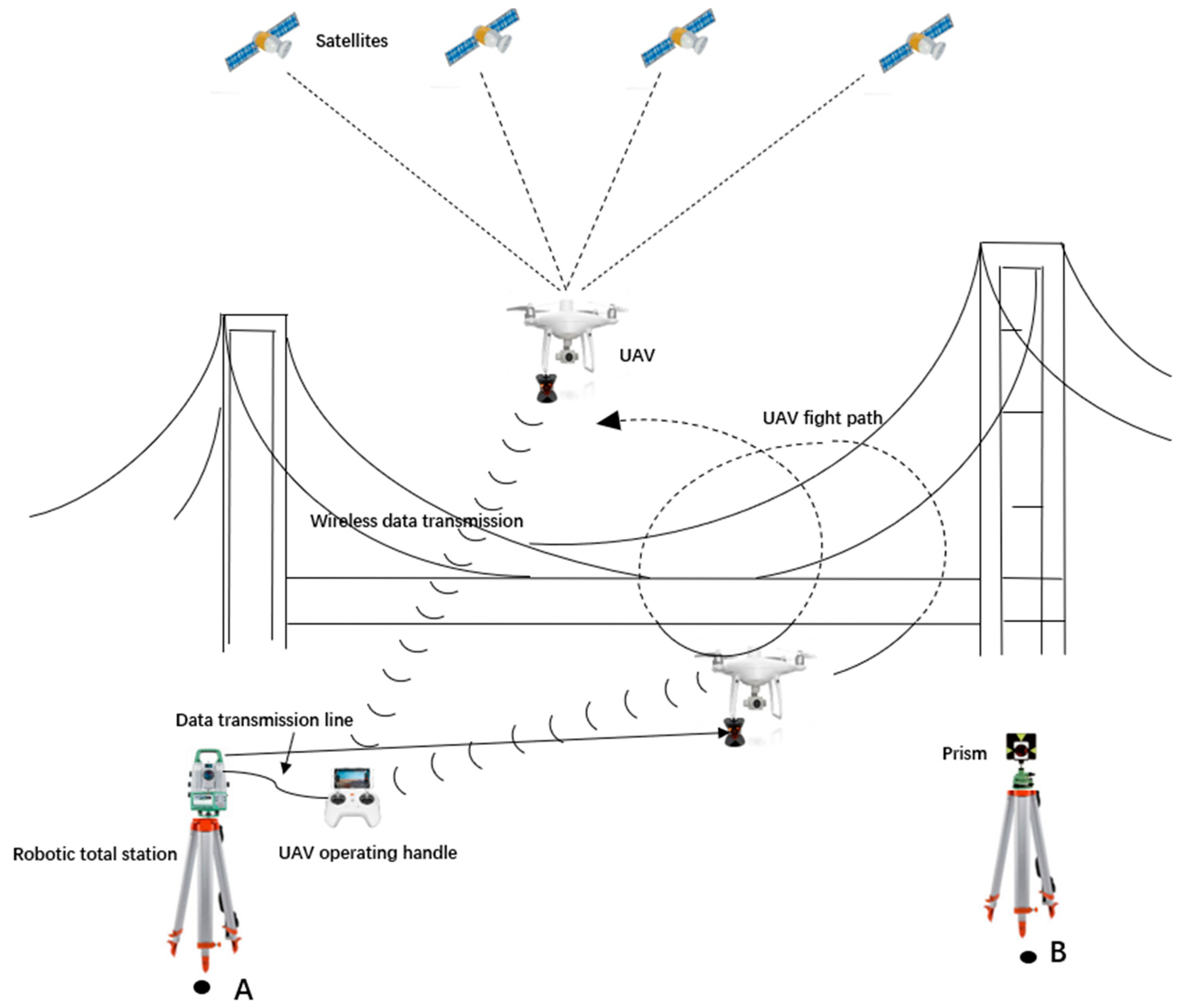
2.3. Real-Time Positioning for UAV

When the UAV is used in structural health monitoring, it usually needs to fly around the structures for full inspection, and the location of the UAV during the flight is essential. On the one hand, it helps us determine the location of defects to later revisit and maintain. On the other hand, possible collision events can be avoided, as the UAV has to fly close to the structure. UAVs are most often located with the GNSS. For complex structures, this method may not work when the UAV flies to GNSS-denied areas, such as the space under bridges. If the total station is used for UAV positioning alone, the UAV may also fly out of the field view of it. In this regard, we propose a real-time positioning method for UAVs combining GNSS and the total station. As shown in Figure 3, when the UAV is not in the line of sight of the total station, for instance, above the bridge deck, the GNSS is used for positioning, and the coordinates obtained are transmitted to the total station for blind tracking. When the UAV flies to GNSS-denied areas and appears in the field view of the total station, for example, under the bridge, the blind tracking mode of the total station is shifted to direct tracking and the coordinates of the UAV can be obtained with it. As different coordinate systems are used by the GNSS and the total station, it is necessary to conduct coordinates conversion with common points first. The flowchart of the proposed method can be seen in Figure 4.

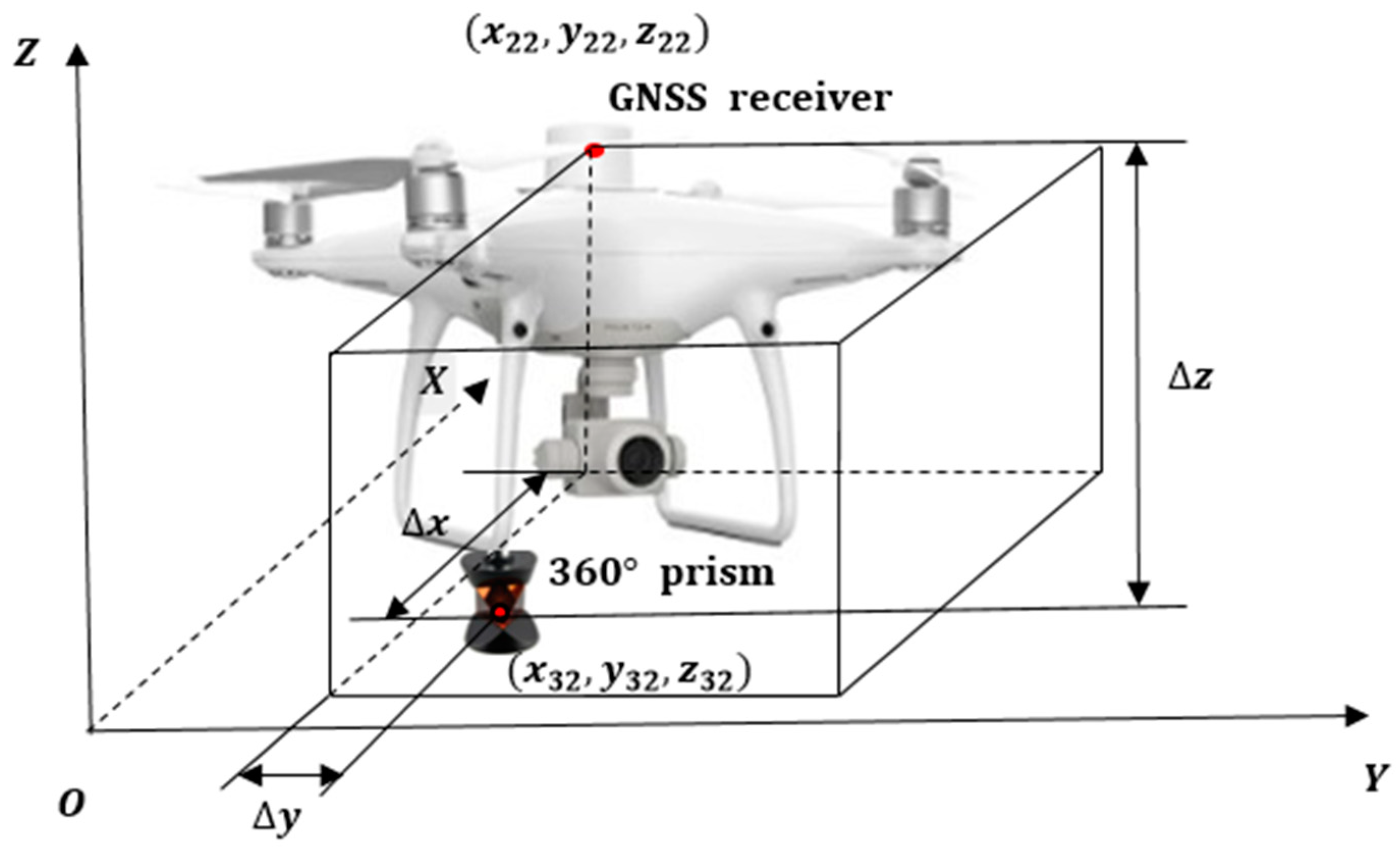
2.3.1. Conversion between Different Coordinate Systems

In order to achieve the positioning goal, at least two common points on the ground are required for coordinates conversion. The selected common points must be in an open field of view, which ensures the line of sight between the common points and that the GNSS receiver can receive enough satellite signals.
Then, use the GNSS receiver to obtain the precise coordinates B i 1 , L i 1 , H   i 1 , i = 1,2 , , n of the common points in the WGS-84 coordinate system.
Finally, use the total station and prism to construct the precise coordinates X i 2 , Y i 2 , Z i 2 ,   i = 1,2 , , n of the common points in the total station coordinate system.
Without considering the height information, the coordinates of the common points B i 1 , L i 1 measured by the GNSS receiver can be converted into the Gaussian coordinates ( X i 1 , Y i 1 ) through Gaussian projection. Set the Gaussian coordinates as coordinate system 1 and the coordinates of the total station as coordinate system 2, and Equations (2) and (3) can be constructed through the common points:
X i 2 = X i 1 cos θ + Y i 1 sin θ + a
Y i 2 = Y i 1 cos θ X i 1 sin θ + b
Write Equations (2) and (3) in matrix form:
X 12 Y 12 X 22 Y 22 X n 2 Y n 2 = X 11 Y 11 1 0 Y 11 X 11 0 1 X 21 Y 21 Y 21 X 21 1 0 0 1 X n 1 Y n 1 1 0 Y n 1 X n 1 0 1 cos θ sin θ a b
where a , b are translation parameters; θ is rotation angle. These parameters can be calculated by least squares.
For the height conversion parameter, the height difference between the two coordinate systems is generally a fixed value within a small area. The height difference in common point H i , i = 1,2 , 3 n is obtained by subtracting from the height H i 1 under coordinate system 1 and the height Z i 2 under coordinate system 2. Take the average value of the height difference in each common point as the final height conversion parameter with Equation (5).
H ¯ = ( H 11 Z 12 ) + ( H 21 Z 22 ) + + ( H n 1 Z n 2 ) n
where i is the common point label, n is the number of common points.

2.3.2. System Requirements

It is necessary to integrate a GNSS receiver with RTK positioning function for the UAV. A 360° prism needs to be installed at the bottom of the UAV, making it possible to be tracked by the total station from different directions. In addition, in order to transmit the GNSS coordinates of the UAV to the total station in real-time for coordinate conversion, it is necessary to establish a data communication link between the UAV and the total station. Generally speaking, there is a wireless data transmission link between the UAV and the controller on the ground, which can transmit the GNSS coordinate of the UAV to the controller. Then it is only necessary to establish a connection between the controller and the total station. Commonly used methods include wireless communication, such as by adding modules such as Bluetooth and Wi-Fi, and the UAV controller can also be connected with the total station through a cable.

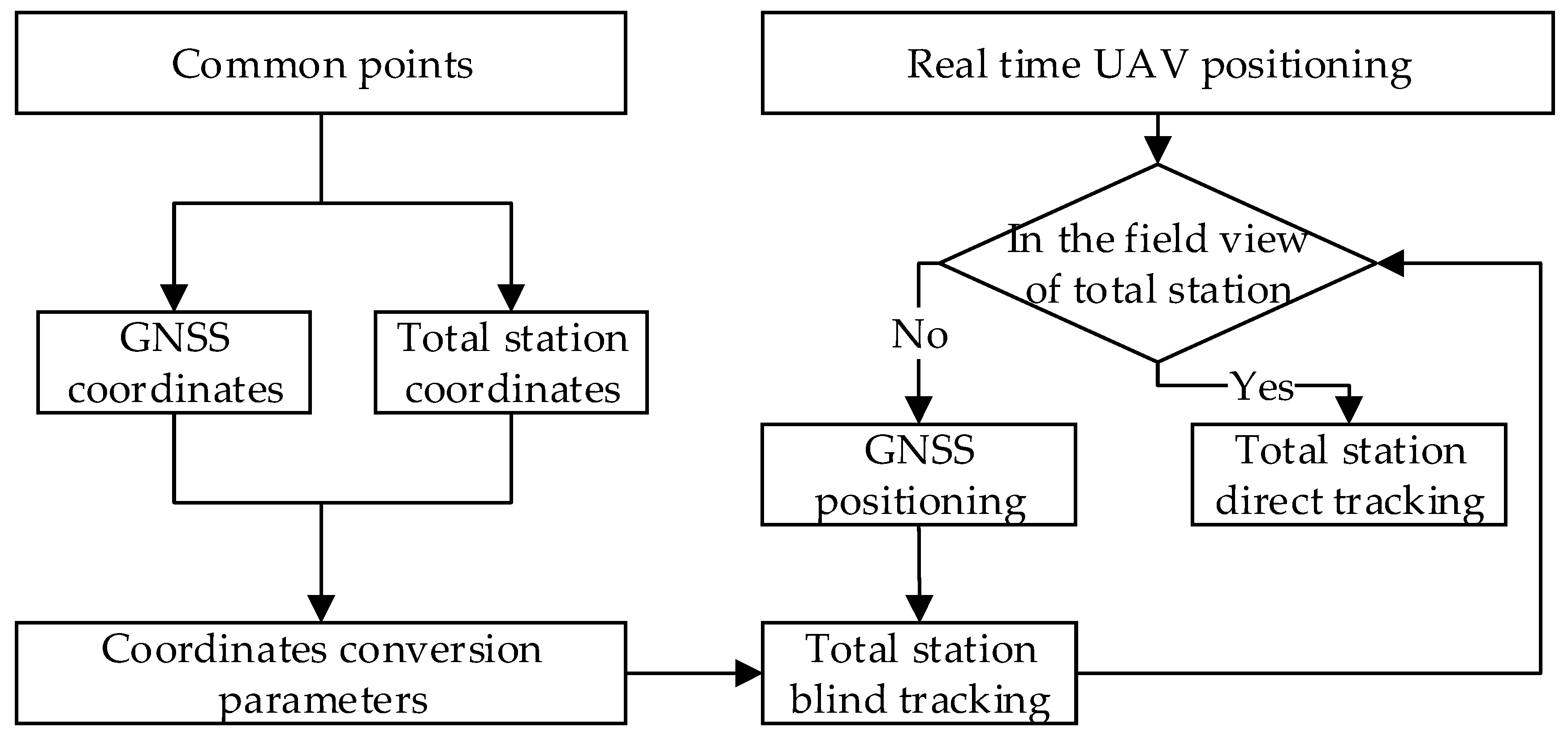
2.3.3. Blind Tracking

When the UAV flies to the bridge deck and is blocked by the bridge deck during bridge inspection, as shown in Figure 3, RTK is used for real-time positioning, and the GNSS coordinates of the UAV are transmitted to the total station through the data communication link. Then the total station calculates the coordinates in its own coordinate system according to the conversion parameters obtained in Section 3.1.
Set the coordinates of the total station as x 12 , y 12 , z 12 , and set the coordinates of GNSS receiver on the UAV in the total station coordinate system after conversion as x 22 , y 22 , z 22 . Since the total station tracks the 360° prism, it is necessary to obtain the coordinates x 32 , y 32 , z 32 of the 360° prism according to the geometry relationship between the GNSS receiver and the 360° prism as shown in Figure 5.
Based on the coordinates of the total station and the 360° prism, the horizontal angle β and the vertical angle α , at which the total station should be adjusted, can be calculated according to Equations (7) and (8), so that it can track the 360° prism blindly. When calculating the horizontal angle β , a constant c should be added to the result of the atan function according to the quadrant of the UAV. The problem of discontinuities induced by the inversion of the functions needs to be considered.
S = ( x 32 x 12 ) 2 + ( y 32 x 12 ) 2 + ( z 32 x 12 ) 2
β = a r c tan y 32 y 12 x 32 x 12 + c
α = a r c sin z 32 z 12 S
Through the calculated horizontal angle β and the vertical angle α , the telescope of the total station is adjusted to perform real-time blind tracking of the UAV. When the UAV appears in the field of view of the total station, it can immediately lock onto the 360° prism to obtain the coordinates of the UAV if it cannot receive enough GNSS satellite signals.

2.3.4. Direct Tracking

In the area where the UAV can be seen by the total station, as shown in Figure 3, the blind tracking mode of the total station is shifted to direct tracking, which means the total station tracks the 360° prism carried by the UAV directly in order to obtain the coordinates of the UAV in the total station coordinate system.
The identification, positioning, and tracking of the prism by the total station are mainly achieved by combination of rough search and precise positioning. For the rough search, the total station is rotated about the vertical axis until the light sensitive element with the large aperture in the vertical direction detects the laser beam that is reflected by the prism. After the coarse horizontal angle towards the prism is determined, the vertical angle is altered until the telescope also roughly points towards the prism in the vertical direction. Then the ATR function is activated, and the telescope moves in a spiral manner until the fine aiming module can accurately aim at the center of the prism. The lock function based on the ATR is further performed to track the prism.

2.3.5. UAV Positioning Mode

(a)
Alternate positioning
For example, when the UAV flies below the bridge deck, it cannot be positioned in real-time through GNSS due to the block of the bridge deck. It can be tracked by the total station. When the UAV flies above the bridge deck, it cannot be tracked by the total station, as it is not within the line of sight of the total station, but at this time the GNSS receiver can receive enough signals to achieve positioning of the UAV.
(b)
Optimal positioning
When the UAV can be positioned both by the total station and the GNSS receiver, the coordinates obtained by the total station are the final coordinates, because the accuracy of the total station is higher than that of the GNSS receiver.
(c)
Post-positioning
In some occasional cases, neither the total station nor the GNSS can be used to obtain the coordinates of the UAV. At this time, post-fitting can be used to obtain the coordinates of the UAV when it collects structural health monitoring data, such as photos containing defects.
For example, the last coordinates of the UAV obtained by the total station or the GNSS at time T 1 are ( x 1 , y 1 , z 1 ) and the coordinates of the UAV obtained by the total station or the GNSS at time T 2 are ( x 2 , y 2 , z 2 ) . During the time period of T = T 2 T 1 , the UAV cannot be located by the total station and the GNSS, and the coordinates of the UAV in this period can be obtained by least squares fitting.

3. Results and Discussions

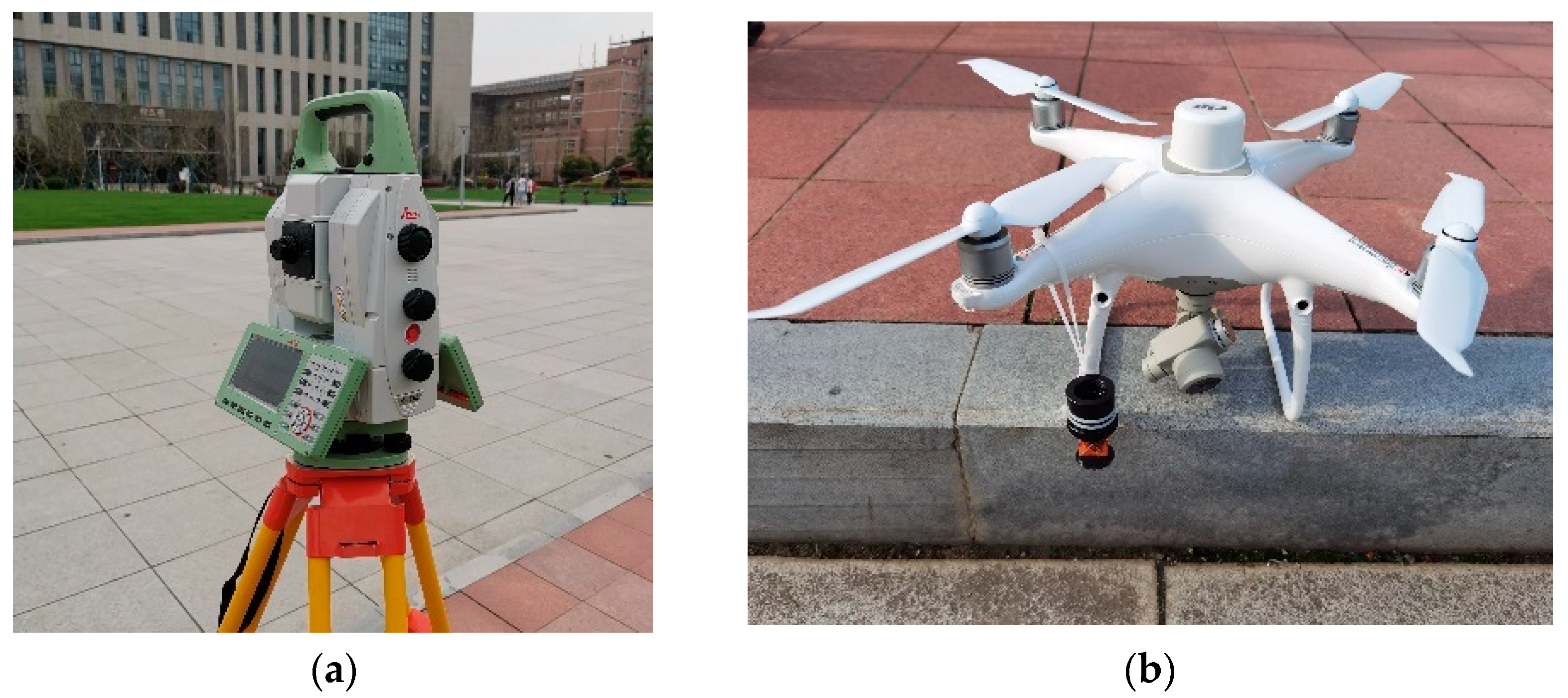
3.1. Experimental Equipment

In order to verify the feasibility and accuracy of the proposed method, a series of experiments were carried out. The experiment equipment included a Leica TS60 total station and a DJI Phantom 4 RTK UAV. As shown in Figure 6a, the TS60 is a self-learning total station that can automatically track the prism at a long distance and obtain high-precision coordinates. As shown in Figure 6b, the DJI Phantom 4 RTK UAV was equipped with a GNSS receiver, enabling it to reach the positioning accuracy of centimeter level with the help of RTK positioning. The detailed parameters of the total station and the UAV are shown in Table 1. In order for the total station to track the UAV, a mini 360° prism was attached to the UAV.

3.2. Positioning Performance Test

First the positioning performance of the total station and the RTK were tested, and an open field was chosen to carry out the experiment. The UAV flew to a height of 20 m and hovered for one minute, then flew for one minute in the vertical plane, and finally flew in the horizontal plane for one minute. The total station tracked the mini 360° prism installed on the UAV to obtain its coordinates at an interval of 0.5 s. The RTK function of the UAV was turned on to obtain its GNSS coordinates at an interval of 2 s. The deviations of the coordinates in each direction under different fight states for the two positioning methods are shown in Table 2. It can be seen that the deviations of the coordinates in different situations are within 0.1 m. Considering the jitter of the UAV in different flight states, the positioning performance of the total station and RTK were verified.

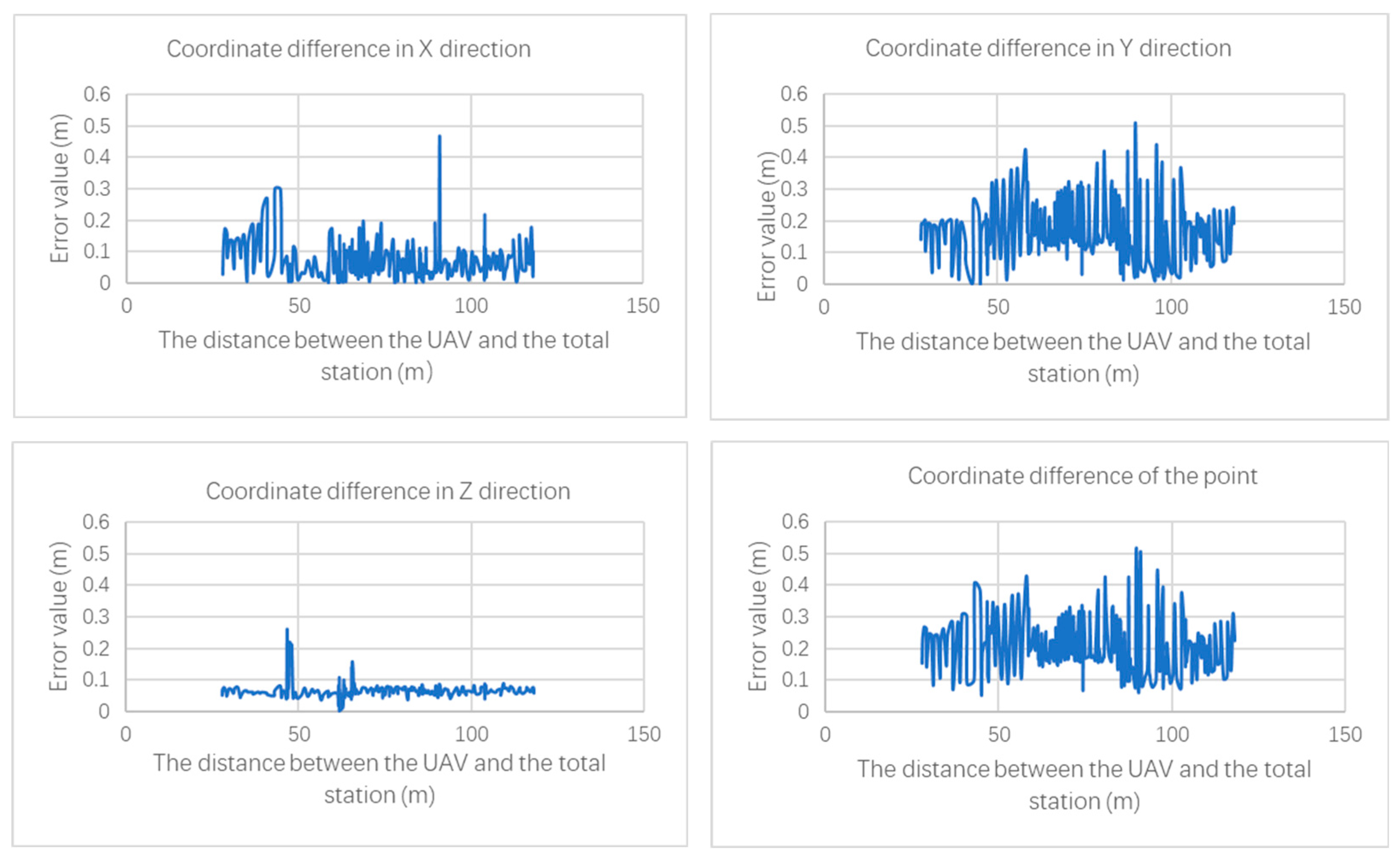
3.3. Accuracy Analysis of the Coordinates Conversion
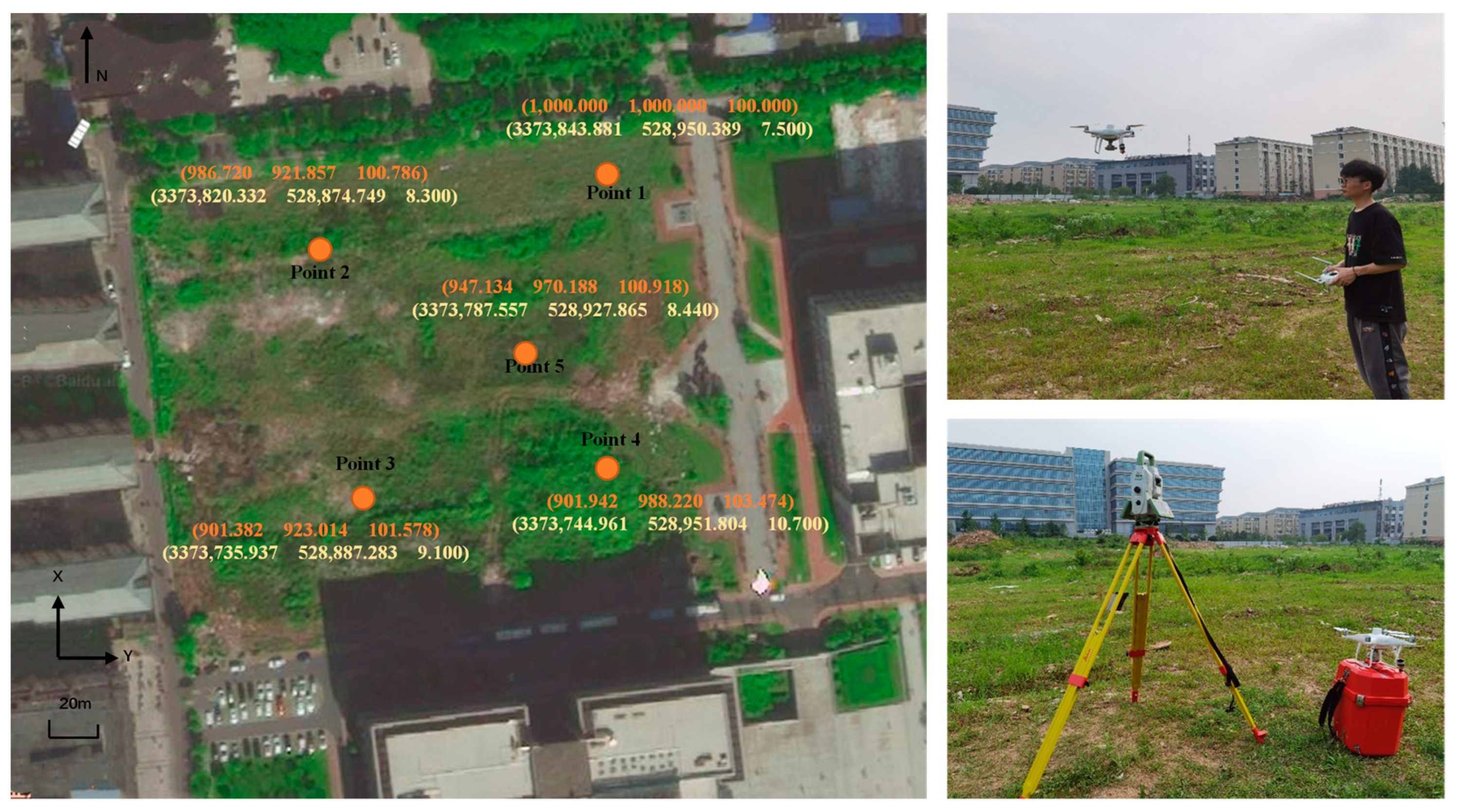
The positioning accuracy of total station is at a millimeter level, but the positioning accuracy of GNSS RTK is only at a centimeter level. Errors can be introduced when coordinate conversion is performed with common points. In order to analyze the influence of the above errors on real-time positioning, an accuracy test was carried out using different numbers of common points. As shown in Figure 7, five common points in an area with 175 m × 150 m were selected on the campus. The coordinates of them were measured with the total station and the GNSS receiver, and they were marked on Figure 6, where orange represented the coordinates measured by the total station, and yellow represented the coordinates measured by the GNSS receiver after Gaussian projection transformation. After synchronizing the total station and the UAV, the total station was set up at point 1, and the UAV flew freely above the area. The total station tracked the mini 360° prism installed on the UAV to obtain its coordinates at an interval of 2 s. At the same time, the GNSS receiver of the UAV obtained its coordinates at an interval of 2 s.
When comparing the coordinates after conversion, it only makes sense when the coordinates in the two coordinate systems were obtained at the same time, as the UAV was not static. The GNSS receiver can obtain the coordinates strictly with a 2 s interval, but the coordinates obtained by the total station could not be at a precise interval of 2 s due to the tracking mechanism. Therefore, it is necessary to align the timestamps of the coordinates acquired through the total station and GNSS receiver through interpolation before the coordinates conversion can be performed.
At least two common points are required for coordinates conversion, and then multiple sets of conversion parameters can be calculated based on the number of common points selected in our test. Taking the conversion parameters calculated with five common points as an example, all the coordinates acquired with the GNSS receiver were converted into the coordinate system of the total station. The differences in each axis of the coordinates obtained with the two methods at the same moment are treated as the conversion accuracy, and are shown in Figure 8.
It can be seen from Figure 7 that, when using 5 common points for coordinates conversion, there is no obvious correlation between the coordinate difference and the distance between the UAV and the total station, and the largest coordinate difference is about 0.5 m. Further, after all combinations are used for conversion, all the UAV coordinates measured by the GNSS receiver are converted into the coordinate system of the total station, and then compared with the UAV coordinates obtained by the total station at the same time. According to different combination forms, the maximum value of the coordinate difference in each combination is shown in Table 3.
It can be seen from the table that no matter how many common points are selected for coordinate conversion, most of the coordinate differences in X and Y directions are around 0.5 m, and their standard deviations are also relatively consistent. It can be concluded that the number of common points has little effect on the conversion accuracy. When using this method to position the UAV, due to the limitations of the surrounding environment of the structure, it is sometimes difficult to find enough common points that are in line of sight; based on the above experimental conclusion, only two common points are enough to meet the positioning accuracy requirement. At the same time, selecting two common points can also reduce the workload.
The ability of the total station to track the prism depends on the magnitude of the converted coordinate difference. When the difference is less than the range of field view of the total station telescope, the automatic target recognition function of the total station can track the prism for positioning, and vice versa, and the UAV cannot be found. As shown in Figure 9, the range of the field view R is calculated with Equation (9):
R = 2 × S × tan F O V 2
where S is the distance from the total station to the UAV; F O V is the field view of the total station telescope.
Taking the five-point combination as an example, the maximum coordinates difference after conversion is 0.515 m. Using the coordinates of UAV of that point in total station system converted from the GNSS receiver, the distance between the total station and the UAV can be calculated as S = 89.706 m . In our experiment, the Leica TS60 total station was used with a telescope field of view F O V = 1.5 ° . Based on Equation (9) the range of the field view can be calculated as R = 2.349   m , which is much larger than the maximum coordinates difference 0.515 m. Therefore, the real-time poisoning of the UAV with total station can be guaranteed.

3.4. Field Test

In order to verify the feasibility of the proposed method, a building which an UAV can fly both above and below on campus was chosen to conduct the field test. First, two common points, TS01 and TS02, around the building were selected. Then the coordinates in the coordinate system of the total station and the GNSS receiver were obtained. Finally, the conversion parameters were calculated following Equations (2), (3), and (5), and are shown in Table 4.
The conversion parameters were typed into the total station, and the total station and the UAV were synchronized. The automatic tracking mode was set for the total station, and the coordinates were stored every two seconds. At the same time, the coordinates obtained from the GNSS receiver on the UAV were acquired at an interval of two seconds.
As shown in Figure 10, the UAV was controlled to fly along the vertical plane of the building. When the UAV was above the building, the UAV was not in sight of the total station due to the shelter of the building itself. At this time, the GNSS receiver could provide the position information, which could be transmitted to the total station through wireless communication. Combined with the conversion parameters, the coordinates of the UAV in the total station coordinate system could be calculated. The total station was driven to track the UAV blindly with calculated coordinates. When the UAV was around the building and appeared in the field view of the total station, the UAV coordinates obtained with the GNSS receiver were (3373419.937, 5290606.193, 31.81); the conversion parameters were used to calculate the coordinates of the UAV in the total station coordinate system as (1041.286,1023.279,123.328); and the ATR function of the total station was activated to track the UAV directly. In this area, the position of the UAV could be obtained through both the GNSS receiver and the total station. When the UAV was below the building, the GNSS receiver could not provide location information because the satellite signal was blocked. The UAV could only be tracked by the total station. The coordinates of the UAV in different coordinate systems during the flight are shown in Table 5 and Figure 11; the red points indicate the coordinates of the UAV in the coordinate system of the total station converted from the coordinates obtained with the GNSS receiver, and the blue points represent the UAV positions obtained with the total station directly. When the UAV can be positioned by both methods, the maximum coordinate difference between them is 0.975 m. The range of the field view of the total station can be calculated as R = 1.309   m according to Equation (9), which was larger than 0.975 m and further verified that the total station can lock the UAV based on the coordinates provided by the GNSS receiver. The field test shows that, in a sheltered environment, the proposed method can achieve real-time positioning for UAVs.

4. Conclusions

It is important to obtain the position of the UAV when it is used for structural health monitoring, but sometimes the UAV cannot receive the GNSS signals due to the blockage of structures. This paper proposes a real-time positioning method combining the GNSS and the total station. First of all, the conversion parameters of the total station and the GNSS coordinate systems are obtained. When the line of sight between the UAV and the total station is blocked, the position of the UAV is obtained through the GNSS and transmitted to the total station. The total station can blindly track the UAV after the coordinates conversion. When the UAV appears in the field view of the total station, the total station can lock onto the UAV and acquire its position information. According to the experiments, the number of common points has little influence on the accuracy of coordinate conversion. The maximum difference in coordinates is 0.515 m when using five common points for conversion, which ensures that the total station can lock onto the UAV, as it is much less than the range of the field view of 2.349 m. The field test verifies that the UAV can achieve real-time positioning when flying at different positions of the building. Therefore, the proposed method is expected to be used in situations where GNSS cannot be fully relied on to obtain the position of the UAV for structural health monitoring. Compared with similar methods in [28,29], where only the GNSS-denied environment is considered, the advantage of the proposed method is that the situation when the UAV is not in the field view of the total station is taken into consideration. Moreover, the proposed method can achieve millimeter-level positioning accuracy, which is better than methods based on Wi-Fi or ultrasonic. However, our method also has certain limitations. It is more applicable to locate the UAV during structural health monitoring for high-rise buildings and bridges. For areas with dense buildings and severe occlusion, multiple total stations may be required to obtain the location of the UAV, which increases the cost. At the same time, we only conducted experiments to verify our ideas, and integrating the positioning system to the UAV platform and realizing autonomous flight during structural health monitoring will be our future research work.

Author Contributions

Conceptualization, J.Z.; methodology, J.Z.; software, J.Z.; validation, L.H.; formal analysis, L.H.; investigation, L.H.; resources, H.L.; data curation, L.H.; writing—original draft preparation, J.Z. and L.H.; writing—review and editing, J.Z. and L.H.; visualization, L.H.; supervision, J.Z.; project administration, J.Z.; funding acquisition, H.L. All authors have read and agreed to the published version of the manuscript.

Funding

This research was funded by the National Key R&D Program of China (2022YFC3005202) and Innovation Demonstration Base of Ecological Environment Geotechnical and Ecological Restoration of Rivers and Lakes (No.2020EJB004).

Data Availability Statement

Data available on request.

Conflicts of Interest

The authors declare no conflict of interest. The funders had no role in the design of the study; in the collection, analyses, or interpretation of data; in the writing of the manuscript; or in the decision to publish the results.

References

  1. Habtour, E.M.; Cole, D.P.; Kube, C.M.; Henry, T.C.; Haynes, R.A.; Gardea, F.; San, T.; Tinga, T. Structural state awareness through integration of global dynamic and local material behavior. J. Intell. Mater. Syst. Struct. 2019, 30, 1045389X1982848. [Google Scholar] [CrossRef]
  2. Masciotta, M.G.; Ramos, L.F.; Lourenco, P.B. The importance of structural monitoring as a diagnosis and control tool in the restoration process of heritage structures: A case study in Portugal. J. Cult. Herit. 2017, 27, 36–47. [Google Scholar] [CrossRef] [Green Version]
  3. Limongelli, M.P.; Previtali, M.; Cantini, L.; Carosio, S.; Matos, J.C.; Isoird, J.M.; Wenzel, H.; Pellegrino, C. Lifecycle management, monitoring and assessment for safe large-scale infrastructures: Challenges and needs. Int. Arch. Photogram Remote Sens. Spat. Inf. Sci. 2019, XLII-2/W11, 727–734. [Google Scholar] [CrossRef] [Green Version]
  4. Zhou, Q.; Ding, S.; Qing, G.; Hu, J. UAV vision detection method for crane surface cracks based on Faster R-CNN and image segmentation. J. Civ. Struct. Health Monit. 2022, 12, 845–855. [Google Scholar] [CrossRef]
  5. Kang, D.; Cha, Y.J. Autonomous UAVs for structural health monitoring using deep learning and an ultrasonic beacon system with geo-tagging. Comput.-Aided Civ. Infrastruct. Eng. 2018, 33, 885–902. [Google Scholar] [CrossRef]
  6. Padró, J.-C.; Muñoz, F.-J.; Planas, J.; Pons, X. Comparison of four UAV georeferencing methods for environmental monitoring purposes focusing on the combined use with airborne and satellite remote sensing platforms. Int. J. Appl. Earth Obs. Geoinf. 2019, 75, 130–140. [Google Scholar] [CrossRef]
  7. Kyriou, A.; Nikolakopoulos, K.; Koukouvelas, I.; Lampropoulou, P. Repeated UAV campaigns, GNSS measurements, GIS, and petrographic analyses for landslide mapping and monitoring. Minerals 2021, 11, 300. [Google Scholar] [CrossRef]
  8. Gül, Y.; Hastaoğlu, K.Ö.; Poyraz, F. Using the GNSS method assisted with UAV photogrammetry to monitor and determine deformations of a dump site of three open-pit marble mines in Eliktekke region, Amasya province, Turkey. Environ. Earth Sci. 2020, 79, 1–20. [Google Scholar] [CrossRef]
  9. Imam, R.; Pini, M.; Marucco, G.; Dominici, F.; Dovis, F. UAV-based GNSS-R for water detection as a support to flood monitoring operations: A feasibility study. Appl. Sci. 2019, 10, 210. [Google Scholar] [CrossRef] [Green Version]
  10. Li, Z.; Zhang, Y. Constrained ESKF for UAV positioning in indoor corridor environment based on IMU and WiFi. Sensors 2022, 22, 391. [Google Scholar] [CrossRef]
  11. Nie, W.; Han, Z.-C.; Zhou, M.; Xie, L.-B.; Jiang, Q. UAV detection and identification based on WiFi signal and RF fingerprint. IEEE Sens. J. 2021, 21, 13540–13550. [Google Scholar] [CrossRef]
  12. Li, Z.; Yin, D.; Xiang, X.; Tang, D.; Zhang, C.; Zhang, S. Research on relative positioning system of UAVs Swarm based on distributed UWB. In Proceedings of the 2020 Chinese Automation Congress (CAC), Shanghai, China, 6–8 November 2020; pp. 5561–5566. [Google Scholar]
  13. Li, K.; Wang, C.; Huang, S.; Liang, G.; Wu, X.; Liao, Y. Self-positioning for UAV indoor navigation based on 3D laser scanner, UWB and INS. In Proceedings of the 2016 IEEE International Conference on Information and Automation (ICIA), Ningbo, China, 1–3 August 2016; pp. 498–503. [Google Scholar]
  14. Muja, M.; Lowe, D.G. Scalable nearest neighbor algorithms for high dimensional data. IEEE Trans. Pattern Anal. Mach. Intell. 2014, 36, 2227–2240. [Google Scholar] [CrossRef]
  15. Tiemann, J.; Schweikowski, F.; Wietfeld, C. Design of an UWB indoor-positioning system for UAV navigation in GNSS-denied environments. In Proceedings of the 2015 International Conference on Indoor Positioning and Indoor Navigation (IPIN), Banff, AB, Canada, 13–16 October 2015; pp. 1–7. [Google Scholar]
  16. Guanglei, M.; Haibing, P. The application of ultrasonic sensor in the obstacle avoidance of quad-rotor UAV. In Proceedings of the 2016 IEEE Chinese Guidance, Navigation and Control Conference (CGNCC), Nanjing, China, 12–14 August 2016; pp. 976–981. [Google Scholar]
  17. Altan, A.; Bayraktar, K.; Hacıoğlu, R. Simultaneous localization and mapping of mines with unmanned aerial vehicle. In Proceedings of the 2016 24th Signal Processing and Communication Application Conference (SIU), Zonguldak, Turkey, 16–19 May 2016; pp. 1433–1436. [Google Scholar]
  18. Han, Q.; Liu, X.; Xu, J. Detection and location of steel structure surface cracks based on unmanned aerial vehicle images. J. Build. Eng. 2022, 50, 104098. [Google Scholar] [CrossRef]
  19. Son, S.W.; Kim, D.W.; Sung, W.G.; Yu, J.J. Integrating UAV and TLS Approaches for Environmental Management: A Case Study of a Waste Stockpile Area. Remote Sens. 2020, 12, 1615. [Google Scholar] [CrossRef]
  20. Mustafah, Y.M.; Azman, A.W.; Akbar, F. Indoor UAV positioning using stereo vision sensor. Procedia Eng. 2012, 41, 575–579. [Google Scholar] [CrossRef] [Green Version]
  21. Saranya, K.; Naidu, V.; Singhal, V.; Tanuja, B. Application of vision based techniques for UAV position estimation. In Proceedings of the 2016 International Conference on Research Advances in Integrated Navigation Systems (RAINS), Bangalore, India, 6–7 May 2016; pp. 1–5. [Google Scholar]
  22. Jingjing, W.; De, G.; Fei, L. Research on autonomous positioning method of UAV based on binocular vision. In Proceedings of the 2019 Chinese Automation Congress (CAC), Hangzhou, China, 22–24 November 2019; pp. 3588–3593. [Google Scholar]
  23. Li, W.; Fu, Z. Unmanned aerial vehicle positioning based on multi-sensor information fusion. Geo-Spat. Inf. Sci. 2018, 21, 302–310. [Google Scholar] [CrossRef] [Green Version]
  24. Zhou, J.; Xiao, H.; Jiang, W.; Bai, W.; Liu, G. Automatic subway tunnel displacement monitoring using robotic total station. Measurement 2020, 151, 107251. [Google Scholar] [CrossRef]
  25. Zhou, J.; Luo, C.; Jiang, W.; Yu, X.; Wang, P. Using UAVs and robotic total stations in determining height differences when crossing obstacles. Measurement 2022, 188, 110372. [Google Scholar] [CrossRef]
  26. Cwiakala, P. Testing Procedure of Unmanned Aerial Vehicles (UAVs) Trajectory in Automatic Missions. Appl. Sci.-Basel 2019, 9, 3488. [Google Scholar] [CrossRef] [Green Version]
  27. Paraforos, D.S.; Reutemann, M.; Sharipov, G.; Werner, R.; Griepentrog, H.W. Total station data assessment using an industrial robotic arm for dynamic 3D in-field positioning with sub-centimetre accuracy. Comput. Electron. Agric. 2017, 136, 166–175. [Google Scholar] [CrossRef]
  28. Ishii, A.; Yasuno, T.; Amakata, M.; Sugawara, H.; Fujii, J.; Ozasa, K. Autonomous UAV flight using the Total Station Navigation System in Non-GNSS Environments. In Proceedings of the International Symposium on Automation and Robotics in Construction, Kitakyushu, Japan, 27–28 October 2020; Volume 37, pp. 685–692. [Google Scholar]
  29. Benjumea, D.; Alcántara, A.; Ramos, A.; Torres-Gonzalez, A.; Sánchez-Cuevas, P.; Capitan, J.; Heredia, G.; Ollero, A. Localization System for Lightweight Unmanned Aerial Vehicles in Inspection Tasks. Sensors 2021, 21, 5937. [Google Scholar] [CrossRef] [PubMed]
Figure 1. The principle of RTK positioning.
Drones 07 00212 g001
Figure 2. The principle of total station positioning.
Drones 07 00212 g002
Figure 3. The schematic of real-time positioning for UAVs with RTK and total station.
Drones 07 00212 g003
Figure 4. The flowchart of the proposed method.
Drones 07 00212 g004
Figure 5. Geometry relationship between the GNSS receiver and the 360° prism.
Drones 07 00212 g005
Figure 6. Experiment equipment (a) Leica TS60 total station (b) DJI Phantom 4 RTK.
Drones 07 00212 g006
Figure 7. Accuracy test of the coordinates conversion.
Drones 07 00212 g007
Figure 8. Coordinates conversion accuracy with 5 common points.
Drones 07 00212 g008
Figure 9. The range of the field view of the total station telescope.
Drones 07 00212 g009
Figure 10. Schematic diagram of the field test. (a) Total station measurement site. (b) Above the building. (c) Around building. (d) Below the building.
Drones 07 00212 g010aDrones 07 00212 g010b
Figure 11. The coordinates of the UAV with different positioning methods.
Drones 07 00212 g011
Table 1. Parameters of the total station and the UAV.
Robotic Total Station
ModelTS60
Angle measurement accuracyHz, V0.5″
Ranging accuracysingle/continuous0.6 mm + 1 ppm/3 mm + 1.5 ppm
Lock and tracking range360° Prism (GRZ4, GRZ122)1000 m
UAV
ModelDJI Phantom 4RTK
Positioning featuresFrequency Used:
GPS: L1/L2; GLONASS: L1/L2; BeiDou: B1/B2; Galileo*: E1/E5
First-Fixed Time: <50 s
Positioning Accuracy: Vertical 1.5 cm + 1 ppm (RMS);Horizontal 1 cm + 1 ppm (RMS).
Velocity Accuracy: 0.03 m/s
Table 2. Deviations of the coordinates in different situations.
Positioning MethodThe Total StationGNSS Receiver
UAV Statusx (m)y (m)z (m)x (m)y (m)z (m)
Hovering0.0530.0400.0230.0770.0330.03
Vertical flight0.0610.053 0.0670.056
Horizontal flight 0.035 0.04
Table 3. Maximum coordinate difference for each combination.
GroupsPoints
Combination
Max-X
(m)
Max-Y
(m)
Max-Z
(m)
Max-P
(m)
SD-X
(m)
SD-Y
(m)
SD-Z
(m)
SD-P
(m)
5 common points123450.4670.5070.2610.5150.0580.0870.0270.082
4 common points12340.4540.5160.2610.5230.0580.0870.0270.083
12350.4900.5110.2610.5270.0600.0860.0270.080
12450.4640.4910.2610.4980.0580.0860.0270.081
13450.4580.5040.2610.5120.0590.0860.0270.081
23450.4720.5230.2610.5310.0570.0890.0270.085
3 common points1230.4840.5240.2610.5330.0600.0870.0270.081
1240.4390.4960.2610.5030.0610.0860.0270.082
1250.4980.4890.2610.5280.0600.0850.0270.079
1350.4890.5040.2610.5240.0600.0850.0270.079
1340.4380.5150.2610.5210.0610.0870.0270.083
1450.4350.4850.2610.4920.0610.0840.0270.080
2340.4530.5460.2610.5530.0590.0920.0270.089
2350.4980.5170.2610.5370.0610.0860.0270.080
2450.4690.5020.2610.5100.0580.0890.0270.084
3450.4820.5440.2610.5520.0580.0920.0270.088
2 common points120.4800.5030.2610.5150.0590.0860.0270.080
130.4820.5200.2610.5290.0600.0870.0270.081
140.3650.4920.2610.5030.0660.0830.0270.080
150.5240.4670.2610.5460.0630.0830.0270.078
230.4980.5380.2610.5490.0610.0880.0270.082
240.4310.5170.2610.5230.0610.0910.0270.087
250.5030.4970.2610.5350.0600.0850.0270.079
340.5030.7410.2610.7450.0700.1140.0270.110
350.4930.4920.2610.5240.0860.0970.0290.079
450.4720.5140.2610.5220.0580.0910.0270.086
Table 4. Conversion parameters.
GNSS Receiver CoordinatesTotal Station Coordinates
x (m)y (m)z (m)x (m)y (m)z (m)
TS013,373,382.54529,031.04488.5510001000100
TS023,373,393.436529,102.41477.631021.3091068.93399.21636
Conversion parameters
a = 3,413,523.545 ( m )
b = 23,750.453 ( m )
θ = 8 ° 29 51
H ¯ = 91.518 ( m )
Table 5. The coordinates of the UAV during the field test.
GNSS ReceiverTotal StationCoordinate Difference
X (m)Y (m)Z (m)X (m)Y (m)Z (m)(m)
Above the building1041.0001023.600124.000
1040.3461024.623124.000
1040.0001025.635124.100
1039.2231026.352124.100
1038.4571027.784124.000
1037.9561028.458124.000
1037.1051029.575123.900
1038.1441030.144124.000
1038.6301030.624124.000
1038.9531031.463124.100
1039.4311031.997124.000
Around the building1041.2861023.279123.3281041.2051023.266123.1900.160
1041.3111023.300123.3081041.0731023.275123.1640.279
1041.1591023.319123.2881041.0151023.294123.1760.184
1041.1261023.329123.3181040.9941023.301123.1960.182
1041.1131023.335123.3281041.0281023.325123.2030.152
1041.1641023.367123.3281041.0281023.365123.1830.199
1041.1391023.410123.2981041.0111023.373123.1750.182
1041.1121023.404123.3081041.0431023.322123.1230.214
1041.1871023.327123.2381041.0641023.251122.7370.522
1041.1711023.263122.6981041.0811023.208122.0130.693
1041.2011023.243121.8681041.1011023.181121.1380.740
1041.2171023.238120.9681041.0661023.151120.1440.842
1041.1461023.203119.9281041.0421023.147119.0860.851
1041.1391023.240118.8981041.0671023.179117.9160.986
1041.1421023.278117.6581041.0611023.208116.6950.969
1041.1241023.298116.2881041.0381023.205115.3210.975
1041.1271023.261114.7881041.0331023.203113.8430.951
1041.1721023.248113.5481040.9921023.273112.8610.711
1041.0931023.251112.6481040.9551023.238112.4620.232
1041.0511023.100112.5681041.2521023.188112.4800.237
1041.7431023.233112.5981042.2701023.525112.4460.622
1042.2421023.437112.5481043.0331023.900112.4780.918
1043.1771023.877112.5981043.8501024.302112.5020.803
1044.4121024.401112.5981044.8311024.795112.4900.585
1045.1871024.911112.5681045.4561025.148112.4560.375
1045.9391025.142112.5681046.3951025.344112.4690.509
1046.8461025.335112.5981047.1411025.457112.4900.337
1047.4551025.534112.5881047.7531025.908112.4710.493
1048.1081026.129112.5581048.2411026.466112.4830.370
Below the building 1048.5991026.849112.524
1049.6931027.621112.508
1050.7051028.366112.477
1051.3871028.788112.491
1052.3641029.367112.504
1053.4531029.985112.478
1054.2511030.423112.644
1055.3751031.104112.843
1056.9431032.099112.971
Disclaimer/Publisher’s Note: The statements, opinions and data contained in all publications are solely those of the individual author(s) and contributor(s) and not of MDPI and/or the editor(s). MDPI and/or the editor(s) disclaim responsibility for any injury to people or property resulting from any ideas, methods, instructions or products referred to in the content.

