1. Introduction
Ellipses are common in natural and artificial scenes. The recognition of geometric shapes formally described by mathematical models has a long tradition in pattern recognition. Similarly, the detection of ellipses has often been solved in the past based on a large number of complex parameters. Ellipses detection from real-world images with a fast and reliable method represents a powerful analysis tool for many computer vision applications. For example, ellipse detection can be used for wheel detection [
1], road sign detection and classification [
2], saliency detection [
3], object segmentation in industrial applications [
4], automatic cell segmentation in microscope images [
4], pupil/eye tracking [
5], etc. Vision-based autonomous landing detection and tracking circles or ellipses in real-time are crucial for many real-world (mainly robot) applications. In this application, many landing areas for aerial robots are composed of elliptical shapes [
6], and autonomous vehicles need to detect circular landmarks first [
7]. Ellipse detection still remains unresolved as one of the typical tasks with a long history. The actual problems such as noise, overlap and occlusion, and the boundary of an ellipse is divided into multiple arcs greatly increase the difficulty of ellipse detection, reduce detection accuracy and speed, and thus cannot be deployed in lightweight robot applications. The implementation of most existing methods does not occur in real-time, which hinders their application in reality. Detecting ellipses in computer vision has been an ongoing topic of interest for researchers [
8,
9]. Many researchers have tried to find novel and effective solutions for ellipse detection in noisy and cluttered images, and have successfully formulated line and circle detection algorithms. The earliest ellipse detection algorithm dates back to the Hough transform (HT) [
10] that is based on accumulation/voting procedures, interpolation, curve fitting, etc. The existing ellipse detection methods are divided into four categories. The first category includes algorithms based on voting, including Hough transform (HT) [
10] and methods based on it. The HT algorithm uses five-dimensional parameter space for ellipse detection, which is too slow and complex for real-time applications. Other methods have been tried to enhance HT [
11,
12,
13] by reducing the parameter space dimensions, and the approximation of piecewise linear curve segments [
14] and the randomization method [
15,
16,
17] have been used. Random Hough transform (RHT) improves performance by reducing the number of edge points and voting with appropriate points. These improved methods are based on HT, which are fast, but usually not accurate, and are not suitable for many robot applications. The second category mainly includes optimization-based methods [
18]. Most popular methods of the category convert the ellipse-fitting problem into a least squares optimization problem to solve in order to find the best fit [
19,
20]. Lu and Tan [
21] proposed an iterative random Hough transform (IRHT), which inherits the advantages of RHT and overcomes noise sensitivity. Tang and Srihari [
22] proposed a method called constraint random Hough transform (CRHT), which selects random points under smoothness, distance, and curvature constraints to detect ellipses in footwear images. The authors also presented a new probabilistic fitness measure to verify. However, these methods are usually unreliable and tend to produce many false judgments. Another group of optimization-based methods was tried to solve the nonlinear optimization problem of fitting ellipses using a genetic algorithm [
23,
24]. These algorithms perform well on noisy images with multiple ellipses, but their processing time makes them unsuitable for real-time applications.
The third category includes methods based on edge linking and curve grouping [
25]. These methods can detect ellipses from complex and noisy images, but they are usually costly and cannot be used in real-time applications. Pătrăucean et al. [
26] proposed a parameterless line segment and elliptical arc detector with an enhanced line segment detector (ELSD). Fornacar et al. [
27] provided a new algorithm called Yet Another Ellipse Detector (YAED), which divides the edge contour into four quadrants, selects three arcs from different quadrants, and constructs candidate combinations with an innovative arc selection strategy. Wang et al. [
28] proposed a top-down fitting strategy to combine edges into ellipses. Jia et al. [
29] proposed an ellipse detection method based on the characteristic number (CNED), which uses improved projection invariants to remove useless candidates. It performs well in terms of execution time and detection accuracy. All these category methods proposed are based on Matlab or OpenCV library, and each of them executes a cycle with a long time and computing resource.
The fourth category includes methods that are mainly used to detect partial arc segments of ellipses to estimate their parameters. Fornacari et al. [
27] and Nguyen et al. [
30] proposed an ellipse detection method that combines arc grouping with Hough transform in the decomposed parameter space to estimate ellipse parameters. In this way, it achieves real-time performance comparable to slower and more robust algorithms. Recently, refs. [
31,
32] proposed similar methods. The author tested these algorithms on static pictures, and implemented them by Matlab platform, which is relatively inefficient and not suitable for low computing resource devices with real-time requirements. The arc support group is formed by iteratively connecting arc support segments that belong to the same ellipse. Wu et al. [
33] proposed a fast method for processing high-resolution images for embedded applications, such as detecting ellipses in high-resolution aerospace images. These methods are suitable for static target detection. They are unreliable, consume more computing resources, and are difficult to deploy in lightweight devices. The more computer threads, the lower the difficulty of deployment.
With the continuous improvement of computer performance, methods based on machine learning detected elliptical objects with prior information based on general learning [
34]. Ren et al. [
35] proposed a fast RCNN method, which introduced an attention mechanism and had a good performance, but was not suitable for embedded deployment. McLaughlin and Alder [
36] proposed a method called UpWrite, which used a Gaussian mixed model (GMM) with Zernike moment characteristics. UpWrite could recognize hand-drawn graphics well, but its speed and recognition of real images were relatively poor. Liu et al. [
37] and Liu and Qiao [
38] used multiset mixed learning (MML) to detect ellipses, which minimized the sample reconstruction error on each ellipse. Arellano and Dahyot [
39] used the idea of point set registration to detect ellipses with GMM, and named the algorithm GMMED. However, a machine learning-based method requires a large amount of image data for each detection object to be collected and enhanced, as well as access to a powerful computing system for training. These methods’ detection accuracy is heavily dependent on model training, and they are best suited for single tasks with low real-time requirements.
Although many ellipse detection algorithms have been proposed for computer vision tasks [
32,
39,
40], their performance will decline when used in actual robot real-time tasks. The challenges in these applications include the following:
- (1)
The ellipse detection algorithm must be operated in real-time (release frequency is higher than 10 Hz); that is, it requires real-time operation on a robot onboard computer with limited computer resources.
- (2)
The elliptical object should be detectable when it is far from or close to the robot.
- (3)
Projection deformation changes the shape of the ellipse. When the ellipse is viewed from various angles, projection deformation occurs.
- (4)
There are various possible lighting conditions in the application scene (for example, weak light such as overcast, dusk, evening, or cloudy, and strong light such as sunny).
- (5)
If the camera is close, the sign pattern may not be visible in all frames due to the reflection of a sign board under a light source (for example, the sun, light bulbs, or another light source).
- (6)
There may be shadows on the sign pattern in some frames (for example, shadows of robots or surrounding trees, or of unmanned aerial vehicle propellers). Simultaneously, some frames may be partially visible (due to occlusion or being outside the camera’s field of view). Worse, the pattern may not exist in the keyframe, which will lead to the risk of losing the tracking target.
Many researchers have developed methods to detect and track elliptical patterns in practical applications by analyzing some of the aforementioned challenges. The NimbRo team [
41] used the circular Hough transform algorithm, which is a slow algorithm, for initial detection at the MBZIRC competition in 2017, and then used other pattern features for tracking. Jin et al. [
42] and Li et al. [
43] used YAED [
27] to detect ellipses when the robot is far from the platform and selected other features in the pattern to obtain a closer frame. An ellipse detector was used to reduce the region of interest (ROI) and improved the speed of detecting ellipses between adjacent frames by enhancing the clustering method. Meng [
44] and Vincze [
45] used the Kalman filter to predict the direction of elliptical motion in the frame, improve the detection speed, and reduce false positives. Altan et al. [
46,
47,
48] use optimization-based and model predictive control methods to realize fast-tracking of dynamic targets utilized on UAV platforms. Unfortunately, the combination of ellipse pattern, robot, and camera in many robot applications makes ellipse detection more dynamic, and the detection algorithm tends to be more complex, resulting in the loss of target tracking in many frames, which reduces detection and tracking speed. A simple and efficient tracking algorithm can improve the robustness of an ellipse detector.
In this paper, a new ellipse detection method is proposed. This method can be implemented in real-time on a quadrotor computer with a low-cost limited computing power on a robot to release robust real-time ellipse detection and tracking. Considering the HSV color space used for the elliptical object detection with specific colors, the region of interest will be more accurate. Assuming that the elliptical target has a specific color, firstly, we convert the input image from the RGB color space to HSV color space, use the prior information of color to accurately obtain the region of interest, and extract all contours. Then solve the eigenvectors of the eigensystem and fit each contour through the non-iterative ellipse fitting algorithm. Next, we test the fitting degree of the estimated ellipse and contour and set up some mechanisms to filter the contour. The remaining contour after the screening was identified as the candidate-detected ellipses. During this process, if there are no remaining contours (for example, there are no ellipse data in the current frame), the algorithm returns a set of empty ellipses. Combined with a simple tracking algorithm, this detection method can significantly improve the robustness, accuracy, and performance of ellipse pattern detection by properly changing the parameters of the detection algorithm. After that, the tracking loss is effectively reduced in the process of operation, and it has been proved that this is faster than using a predictive filter. Finally, the results are shown that the proposed method has the best performance (precision, recall, F-Measure scores) and the least execution time compared with the other nine most advanced methods on three public actual application datasets. Quantities of different indoor and outdoor practical light conditions experiments are verified that the proposed ellipse detector and simple tracking method can adapt to detect elliptical patterns under outdoor natural conditions, and even if there is only part of the pattern in view. The algorithm is tested on video streams in actual application scenarios, and its detection and tracking performance are evaluated at different distances. Our method can detect elliptical markers online and in real-time. The ellipse can be well detected when the elliptical object was far from or close to the robot. Severely blocked ellipses can still be detected. Meanwhile, when there is specular reflection, the robot can detect elliptical markers. The average detection frequency can meet the real-time requirements (>10 Hz). The detection of UAV charging base stations in smart cities, the recognition and tracking of elliptical objects, and the autonomous landing of UAV express are just a few examples of situations where our method can be employed broadly.
The rest of this paper is organized as follows. The ellipse detection and tracking algorithm based on HSV space is introduced in
Section 2.
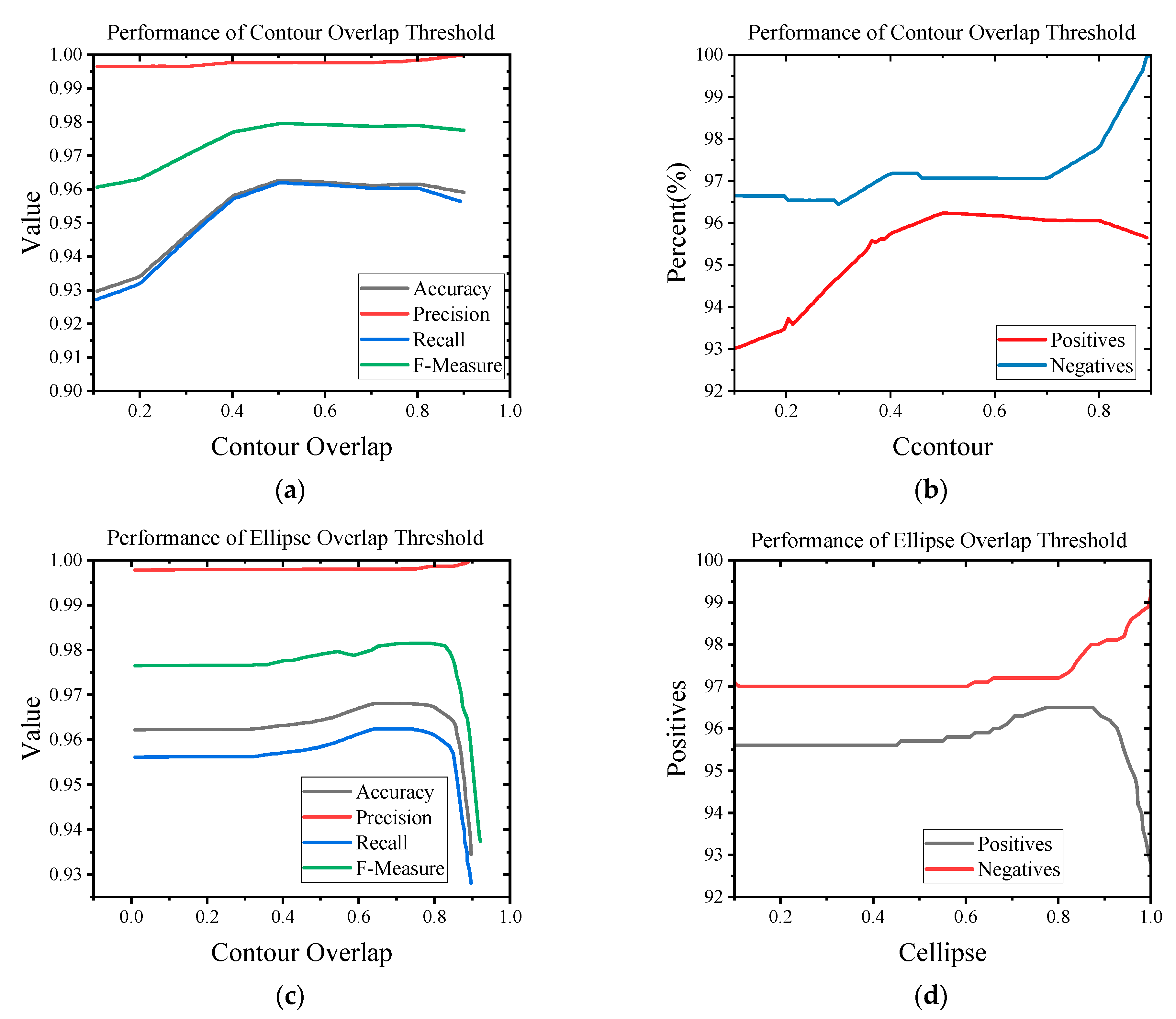
Section 3 presents the experiments that are designed to verify the sensitivity of the algorithm parameters.
Section 4 describes the testing of the performance of the proposed algorithm on a public image dataset and video streams in an actual robot application scenario compared with other known methods. In addition, an oval landing board icon was designed to dynamically test the robustness of the algorithm under different indoor and outdoor lighting conditions and at different distances. Finally,
Section 5 presents the conclusion and discusses how to further improve the proposed method in the future.
2. Ellipse Detection and Tracking in HSV Space
Under natural lighting conditions, it is easier to use the HSV color space to track objects with obvious color characteristics than the RGB color space. The HSV color space is often used to segment objects with specified colors. The idea of the ellipse detection algorithm in the HSV color space based on color filtering proposed in this paper is to fit the ellipse to all contours in the frame or region of interest, and then determine whether the ellipse is suitable. The region of interest comes from extracting specific colors in the HSV color space. The HSV space can reduce the undesired effects of non-uniform illumination. After extracting the ellipse contour, the real-time ellipse fitting algorithm and the strategy to quickly evaluate the fitting result are used. After estimating, it becomes a real-time detection algorithm. In addition, the algorithm can detect an ellipse when all or part of the contour of the ellipse pattern is extracted. With a proper contour extraction method, the detection becomes robust to changes in illumination and the environment.
2.1. Color Filter
A color filter to filter out the red pixels in the original color image and convert them into binary images was designed. Assuming that the acquired image is an 8-bit, 3-channel RGB color space, Algorithm 1 compares pixels of one specific main color with the two other colors and retains the red channel.
| Algorithm 1: Color filter algorithm |
| Input: RGB image |
| Output: Binary image frame matrix |
| 1: ), where each is a matrix of a 8-bit, 1 channel image frame from usb_cam node.
|
| 2. get Binary Image of Color ()
|
| 3. for every pixel value of i-th row and j-th column in the matrix |
| 4. if then |
| 5. |
| 6. else |
| 7. |
| 8. end if |
| 9. end for |
| 10: return |
The input image from the RGB color space is converted to the HSV color space, where H, S, and V represent hue, saturation, and value. The conversion process is shown in Formulas (1)–(3), where 𝑟, 𝑔, and 𝑏 are the RGB values of the image, and
max and
min are the maximum and minimum values of the channel. After color filtering, the S-channel component is taken and the interference part in the image is suppressed by the dynamic threshold (Ostu) algorithm [
49], and the result is closed to eliminate small holes in order to avoid misjudgment of the algorithm. In the HSV space, H represents the color of light, S represents the depth of saturation, and V represents brightness. The colors used to convert the RGB to the HSV color space can be arbitrarily selected. In principle, any color that is obviously different from the color in the application environment can be selected.
Assuming the application is a red ellipse, the color range of red in the HSV space is shown in Formula (4):
Through the above calculation, we can obtain a reddish region of interest (RROI) that contains ellipse information.
2.2. Ellipse Detection
The idea of the ellipse detection algorithm proposed in this paper is to fit the ellipse to all the contours in the frame or region of interest, and then determine whether the ellipse is suitable. Using the real-time ellipse fitting algorithm and the fast standard for checking the fit, the result is a real-time detection algorithm. As long as the contour of the ellipse pattern is extracted (at least partially) during the contour extraction, the algorithm can detect the ellipse. With a proper contour extraction method, the detection becomes robust to changes in illumination and the environment.
The detection function receives a set of thresholds used in the frame and function, and returns a set of detected ellipses. The algorithm is carried out step-by-step as follows:
(1) The first step is to extract edges from input frames and create edge images. In this paper, the adaptive Canny edge detection operator [
50] was used to avoid the low generalization ability of the algorithm and reduce the impact of parameter selection on its effectiveness. In practical applications, the selection of threshold needs to take into account the possibility of extracting appropriate edges under various conditions (such as illumination), and at the same time prevents the generation of too many edges, an increase in the calculation amount, and false detection rate. Generally, it is beneficial to generate more edge information for smaller targets, which can reduce the probability of obtaining elliptical targets without edges but will increase the processing time. In this paper, we extracted contour edges in the HSV space. By extracting the target color, the contour can be effectively reduced and the algorithm complexity can be reduced.
(2) The algorithm proposed by Suzuki and Keiichi [
51] is used to extract the contour using the obtained edges. This step helps to establish connections between related edges and allows the extraction of shapes in the frame. Ideally, each contour is a collection of connecting points that construct the shape boundary in the edge image.
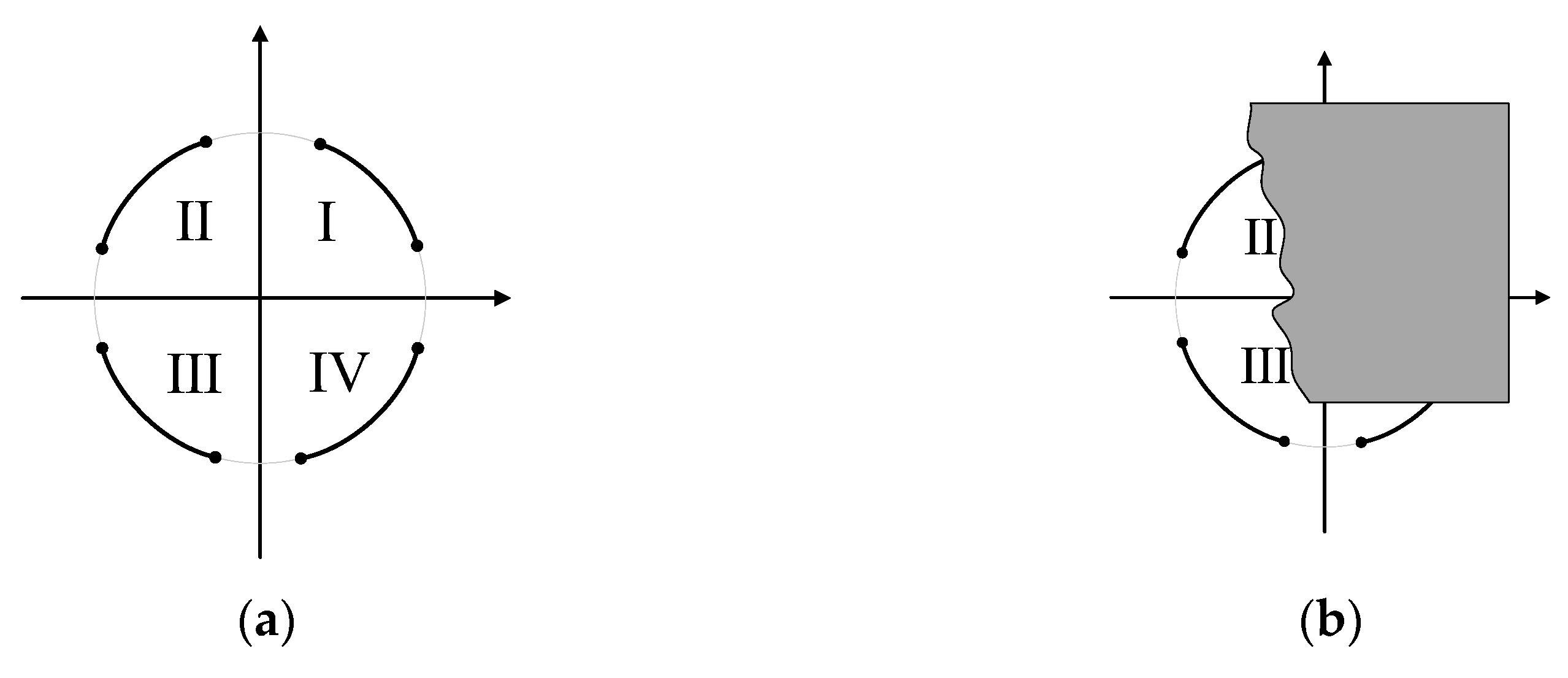
(3) Each contour is processed separately to determine whether it is part of the ellipse, as shown in
Figure 1. For robot applications, the shape of the ellipse in the recognition process can have one of the following contour types:
(a) A single contour containing a complete ellipse without any occlusion, broken line segments, or additional contours, such as the gray complete contour in
Figure 1a.
(b) A single contour containing an ellipse, which comes from the additional connecting contour of the rest of the pattern, such as the four arcs in the four quadrants in
Figure 1a.
(c) A single elliptical contour partially occluded by other objects, as shown in
Figure 1b.
(d) A combination of the above contour types is shown in the splicing of arcs in any three quadrants in
Figure 1a.
To correctly detect the contour types, the following operations are performed for each contour:
(i) If the number of pixels contained in the contour is very small, ignore it and consider the contour as noise.
(ii) Use the non-iterative method based on Fitzgibbon and Fisher [
52] for ellipse fitting on the detected contour, wait for further processing, and screen out the real ellipse. The ellipse fitting method will be introduced in the next section.
(iii) Formulate contour screening rules. If any axis is too small or the eccentricity of the ellipse is very high (close to 1), the generated ellipse will be ignored, because, at high eccentricity, the ellipse generated by data fitting in the contour will be similar to a straight line rather than a real ellipse.
(iv) Rule I: The current contour intersects with the fitted ellipse, and the fitted ellipse is described by the center point of the ellipse, the minor axis and the major axis, and the rotation angle. Then, calculate the ratio
of contour pixel to ellipse pixel obtained by fitting the contour:
where
represents the number of pixels. A lower
value means that the contour does not match the generated ellipse perfectly, and most of the pixels of the contour are not on the fitted ellipse. In this case, the contour will be ignored and will not be processed further.
(v) Rule II: The fitted ellipse intersects with the contour edge, and the ratio
of the number of pixels at the intersection to the number of pixels in the ellipse is calculated:
where,
is the same as above. A lower
means that the important part of the ellipse does not correspond to any contour in the image. At this point, the ellipse intersects with the edge image rather than the contour of the constructed fitted ellipse, which is mainly caused by noise or imperfect contour detection steps. Because the ellipse at this time has been divided into two or more contours, as shown in
Figure 1a, the ellipse contour is composed of multiple arcs, with each arc corresponding to a different ellipse. In this case, a smaller
ratio is obtained by detecting the ellipse from a single contour, which leads to false detection.
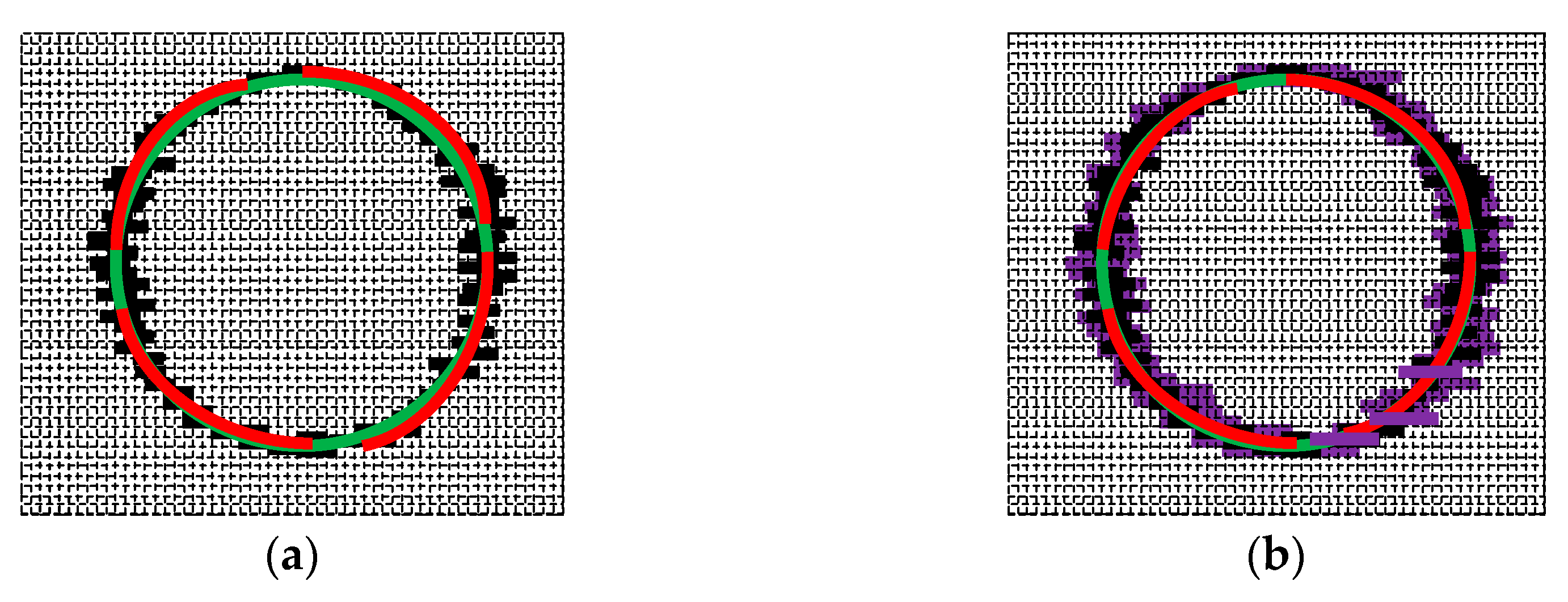
(vi) Rule III: In order to detect the ellipse contour formed by multiple arcs (
Figure 1a), only the actual ellipse pixels in the frame image need to be calculated at this time. Otherwise, if the
value is too small, the detected ellipse may be ignored and the detection accuracy will be reduced. In addition, in order to make the algorithm more robust to slightly imperfect ellipses, the thickness of the edge is increased before the edge intersects the ellipse to reduce the false detection rate, as shown in
Figure 2. The contour obtained by the general Canny edge detection algorithm and its corresponding elliptical arc is shown in
Figure 2a. After increasing the edge thickness,
and
reduce the number of ellipses fitted by the arc segment. During the optimization process, edge thickness of only 1–3 pixels is increased to prevent it from being too large and reducing the accuracy of the ellipse center. In
Figure 2b, the purple outline indicates a thickened edge. The specific implementation is as follows: before obtaining the RROI, first perform morphological corrosion and then morphological expansion to effectively expand the contour edge.
(vii) If the ellipse is not discarded in the previous step, it represents the real ellipse in the image and is added to the detected ellipse set.
(4) Due to the thickness of the ellipse edge, it is possible to detect two or more concentric ellipses during the fitting process. Therefore, a set of detected ellipses returned in the frame is further processed by limiting the ellipse parameters in order to find concentric ellipses. If this happens, all non-central ellipse edges will be ignored. This algorithm can also detect partially occluded ellipses or ellipses that partially exceed the image boundary.
In robot applications, a priori information is often set for elliptical objects. The pinhole camera model can select a higher discard standard for elliptical detection to eliminate potential false detection. Therefore, it is beneficial to have a higher rejection threshold when there is no prior information about the position and size of the elliptical target image. Generally, when the elliptical pattern is detected for the first time in the robot’s field of vision, the geometric parameters of the elliptical target can be obtained, which can be used as the initial parameters and conditions for subsequent detection to enhance the performance and improve the detection rate. Reducing the detection threshold can reduce the probability of losing the target ellipse in subsequent frames due to illumination changes, noise, occlusion, or other condition changes. In addition, if the approximate movement of the target is known and the target is single, the specific color region of interest (SCROI) can be used as the input for the algorithm, and an ROI with a smaller scale can be used as the input frame for detection, which can significantly reduce the image processing time and detection of errors. Ellipse detection on smaller input frames requires less CPU time and is faster.
The pseudocode of the ellipse detection algorithm in HSV space is Algorithm 2 as following:
| Algorithm 2 HSV Color Space Ellipse Detection algorithm |
| Input: |
| Output: A filtered ellipse matrix |
| 1: function DetectEllipse(, )
|
| 2:
|
| 3: ▷ Initialize an empty matrix for the detected ellipses
|
| 4: 0
|
| 5. function DetectEdge()
|
| 6: |
| 7: function ExtractContours (edges)
|
| 8: |
| 9: for all do |
| 10: ▷ Filter small contours or large contours
|
| 11: if then Continue |
| 12: function Filtellipses ()
|
| 13: Filtellipses ()
|
| 14: function CulculateEllipseParameter ()
|
| 15: Filtellipses ()
|
| 16: ▷ Reject oversized ellipses
|
| 17: if then Continue |
| 18: if then Continue |
| 13: ▷ Calculate axis ratio to each ellipse
|
| 14: function CalAxisRatio ()
|
| 14: |
| 15: if then Continue |
| 16:
|
| 17: ▷ Reject contours with small overlap with ellipse
|
| 18: |
| 19: if then Continue |
| 20:
|
| 21: ▷ Ignore contours with small overlap with ellipse
|
| 22: |
| 23: if then Continue |
| 24:
|
| 25: ▷ Get detected ellipse
|
| 26: |
| 27: end for |
| 28: return |
| 30: end function |
2.3. Ellipse Fitting
Ellipse fitting is very important in ellipse detection because it directly affects the accuracy. The ellipse fitting method based on the least square method focuses on finding the residual between the contour minimization point and the ellipse [
19,
53,
54]. Because the constraint of the ellipse fitting problem is quadratic, the efficiency is usually not ideal in the iterative process. Therefore, Fitzgibbon et al. [
19] proposed a non-iterative algorithm by solving the positive eigenvector of the eigensystem. However, the solution efficiency is low. This paper improves the method proposed by Fitzgibbon [
19] and adds a rule to reasonably avoid invalid iteration to reduce the calculation time.
Suppose we have a set of contour points
:
in which there are
data points. The
contour datasets correspond to
ellipse datasets, which are denoted as:
Then, we calculate the scatter matrix of dataset
:
where
is denoted as:
Then, we solve the generalized eigensystem
, where
is the constant constraint matrix:
Therefore, the eigenvector with positive eigenvalues is the ideal fitting ellipse of contour dataset .
In the actual ellipse detection process, more than one ellipse contour will be detected in each frame of the image, and
ellipses will be obtained after fitting. We can find the most suitable fitting ellipse by trying to fit a large number of different datasets. Assuming that the detected contour set
calculated
to fit an ellipse, several additional point sets belonging to the same ellipse can be found. These additional point sets are composed of
,
,
,
, meaning that the effective calculation method for fitting the new ellipse should be based on the previous calculation results. The design matrix and scattering matrix of
are respectively expressed as
and
. Therefore, design matrix
of
point sets can be expressed as:
The corresponding scattering matrix
is:
and we let
Then we substitute Formula (14) into Formula (13) to get:
Thus, Formulas (13)–(15) show that the scattering matrix of any combination point set is equal to the sum of the scattering matrices of each point set. At the same time, every time an ellipse is detected, especially in the tracking task, the scattering matrix of each ellipse point set group only needs to be calculated once in the adjacent frame. When fitting one or more contour sets into an ellipse, the above superposition characteristics can reduce the calculation time.
2.4. Tracking an Elliptical Target
In order to track the detected ellipse pattern in the next frame more effectively, a simple and efficient tracking algorithm is proposed. Considering that the above algorithm can be widely used in robot applications in a natural light environment, the impact of light on the accuracy of the algorithm cannot be ignored.
For image filtering, when the camera attitude changes slowly, the natural image usually changes slowly in space, so the adjacent pixels will be closer. However, this assumption becomes untenable at the edge of the image. If we also use this idea to filter at the edge, that is, if we think that the neighbors are close, the result will inevitably blur the edge, which is unreasonable. Bilateral filter (BF) is a nonlinear filtering method that combines the spatial proximity and pixel similarity of the image to obtain a compromise processing method. At the same time, it takes into account the spatial information and gray level similarity to achieve the purpose of preserving the edges and denoising. It is simple, non-iterative, and local. After being processed by the bilateral filter, the influence of light can be weakened and more edge information can be retained.
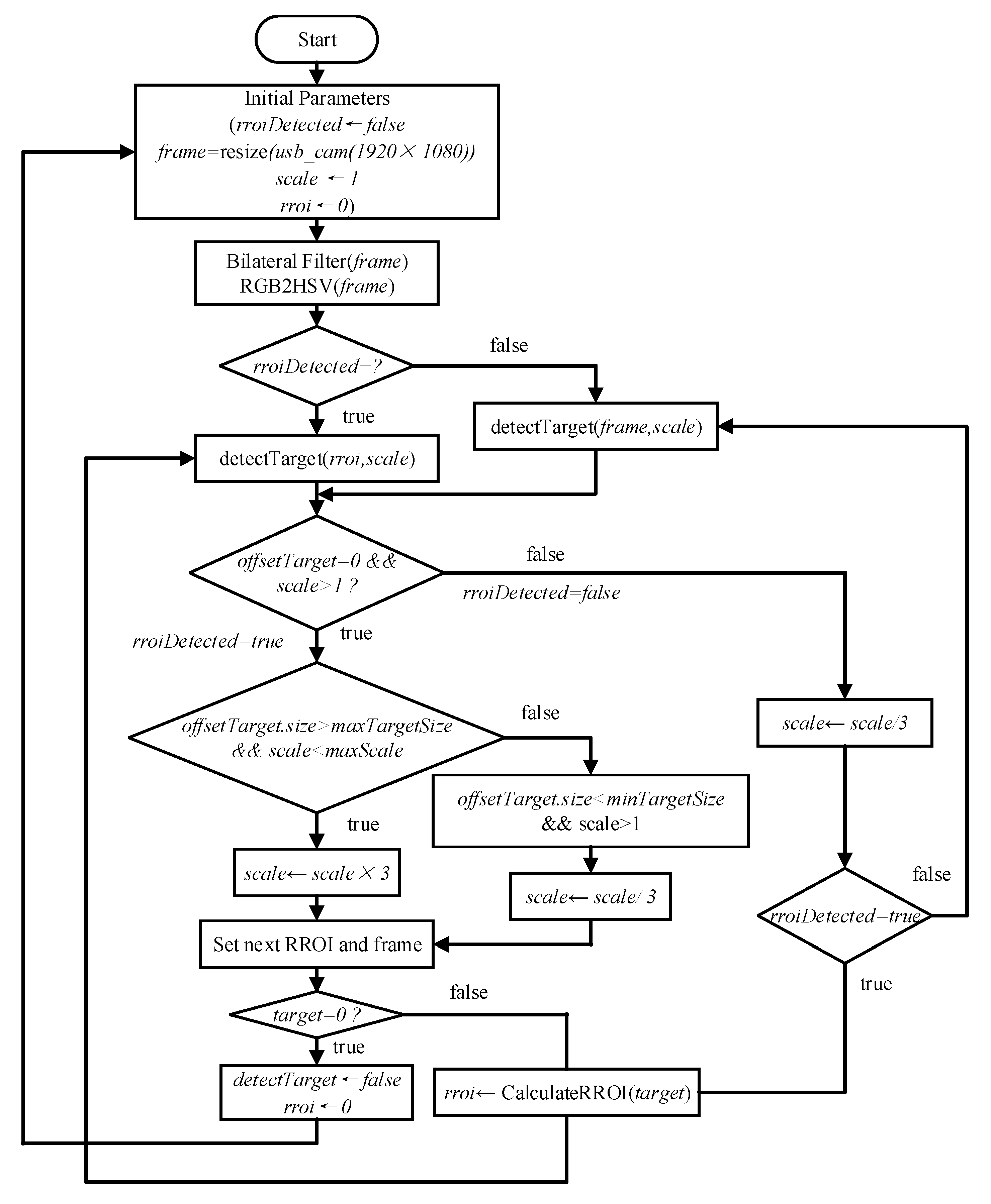
The function of the ellipse target tracking algorithm based on RROI is to track the ROI of adjacent frames, discard the data beyond the ROI, ensure the effective pixel value of the contour, and set the target parameters of the next frame. The algorithm flowchart is shown in
Figure 3.
These steps can be combined with ellipse detection algorithm to more effectively track the detected ellipse pattern in the next frame:
(1) Receive node usb_cam from ROS, with an input image of 1920 × 1080, and initialize algorithm parameters and status. Python has an RROI detection status and image processing library to realize image scaling, bilateral filtering, and other operations.
(2) Using the prior information of the ellipse and the initialization of the algorithm after the first detection of the ellipse, the pixel ratio of and will be reduced. After that, the detection result of the ellipse in the previous frame will be used as the initialization parameter for the next frame, so that and form a dynamic mechanism to help the algorithm continuously detect and track targets.
(3) Convert RGB space into HSV space, detect the RROI of the region of interest of a specific color, confirm that the ellipse is in the RROI or the current frame image, and extract the ellipse to obtain the offset target of the undetermined target.
(4) One color in the target’s prior information is used to determine the region of interest of a specific color, which includes the currently detected target, and the edge pixels are expanded in all directions based on the distance from the target, the relative speed and mode of the robot, and other available information, to increase the probability of obtaining a concentric ellipse. For example, if the distance is far and the relative attitude change is controllable, the current ellipse parameters are used to predict the target to be found in the next frame and thus approach the current detection coordinates.
(5) When the detected target is larger than the specified size, the frame processing time is reduced by ROI, and the useless frame is discarded to improve the detection efficiency. In order to make the method more robust, if no candidate target is found at a lower scale, ellipse detection is performed again with initial higher parameters and at a higher scale.
(6) From the current frame to the next frame, efficient RROI tracking and continuous real-time detection of elliptical targets are realized.
4. Experimental Analysis and Discussion
This section describes the extensive and detailed experiments that were carried out. In order to verify the effectiveness of our method, we compared it with the most advanced methods in the existing public datasets and real scenarios. The experiment was divided into several parts: (1) experimental setup, (2) introduction of the dataset, (3) comparison with the most advanced methods available, (4) testing in an actual scenario, and (5) discussion of the proposed method.
4.1. Experimental Setup
- (1)
Evaluation criteria
We used the precision, recall rate, and F-measure mentioned in
Section 3.2.
- (2)
Experimental platform
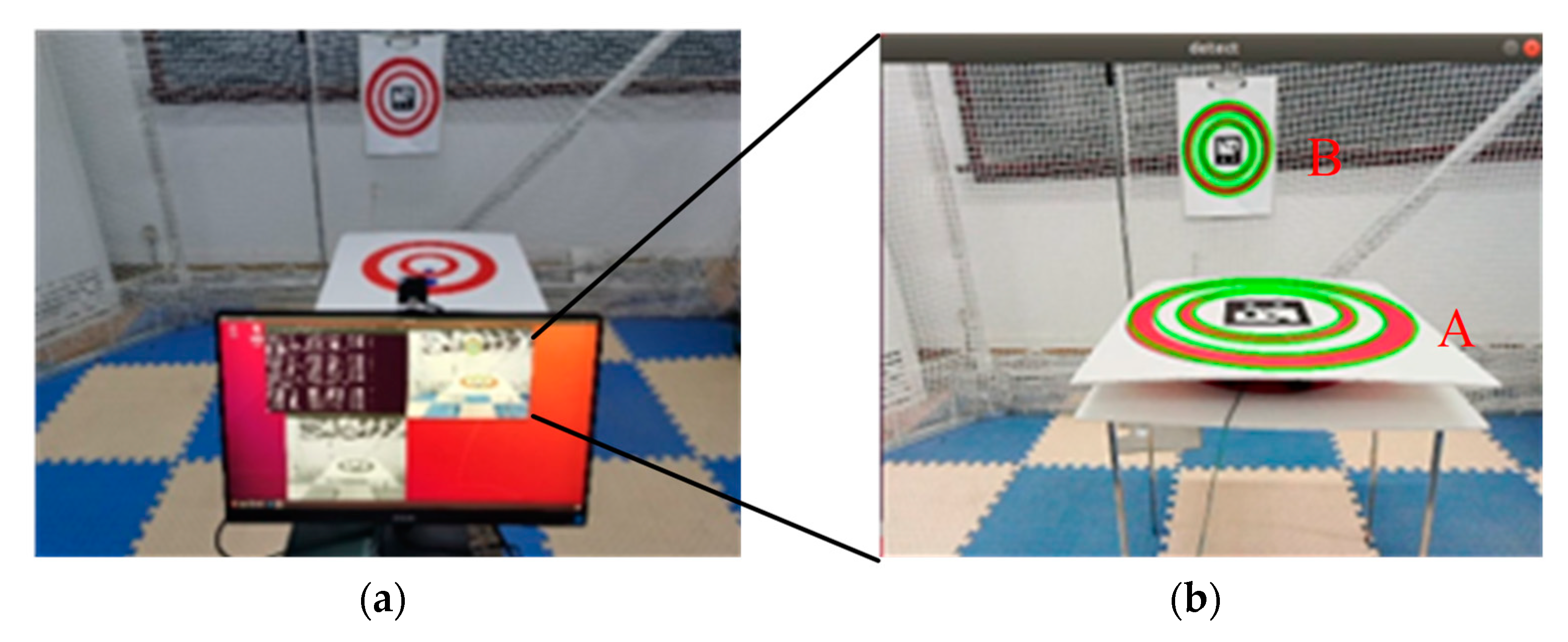
All experiments were performed with default parameters on the same DJI Manifold 2 on-board computer with Intel Core i7-8500U, 2 GHz CPU, Ubuntu 18.04 Linux system, and 8 GB memory (
Figure 6a).
The actual experiment was tested on a self-designed quadrotor. The image acquisition sensor was a low-cost USB monocular camera with resolution of 1920 × 1080 (
Figure 6b).
4.2. Testing on Existing Public Dataset
- (1)
Datasets
Prasad et al. [
56] proposed an ellipse detection method and established 1200 synthetic images and the Caltech 256 real scene dataset. This algorithm is mainly used for robot applications, so the performance test dataset selects real scene image data in the Caltech 256 dataset, which is widely used. Three datasets were used to test the algorithm, and the detection results were compared with those of the most advanced methods. The three datasets were the traffic sign dataset created by Fornaciari et al. [
27], which contains 273 images with various ellipses that are projected by round traffic signs in different real-life scenarios; the Prasad dataset, established by Prasad; and a random picture dataset of real scenes, containing 198 small images with sizes of 107 × 138 to 800 × 540.
On this basis, elliptical target images of traffic markers or landing markers commonly used by some robots were added, such as with “H” or “+” embedded in the circular pattern, or with Aruco QR code embedded [
57]. We used datasets that are similar to actual application scenarios, so that they would be more targeted and better reflect the effect of the algorithm.
Finally, the algorithm was deployed on the UAV, and targeted experiments were carried out on actual application scenarios in which indoor and outdoor light changes were obvious.
- (2)
Reducing linear noise
Considering the actual application scenario, the quality of data collected by the camera is inevitably affected by noise. Here, the consistent bilateral filter described in
Section 2 was used to ensure that the experimental results would be consistent with the results of the proposed algorithm. In order to be fair, the input image was pretreated by a bilateral filter before the methods were compared.
4.3. Comparison of Datasets
In experiments using the mentioned datasets, we compared our method with other state-of-the-art algorithms, as described in
Section 1: CRHT [
22], Prasad [
56], ELSD [
26], YAED [
27], Wang [
28], RCNN [
35], CNED [
29], and Liu and Qiao [
38].
CRHT is the most popular in the literature and is often used as the baseline method. ELSD is robust and achieves precise location accuracy among the state-of-the-art methods. The Prasad method combines HT and the technique of edge following to achieve very good detection performance. YAED and the method of Liu et al. [
40] are very efficient and obtain extremely high F-measure scores on public datasets. YAED is used in a small number of robotics industries that do not require high real-time performance. RCNN is a typical machine learning method that represents a more advanced theory. Considering that ELSD detects elliptical arcs, we reserved ellipses with semi-short length greater than 9 and circumference greater than π. For a fair comparison, we adopted the source codes of ELSD, Prasad, YAED, RCNN, CNED, and Wang, which are available online, and the rest of the methods from the original papers and other code contributors. The CRHT, Prasad, and Liu, methods were run in MATLAB 2020b, while ELSD, YAED, Wang, CNED, and our method were in C++. RCNN [
35] was a Python program and our algorithm was in C++ running on the same portable lightweight DJI Manifold 2 on-board computer as an ROS package node.
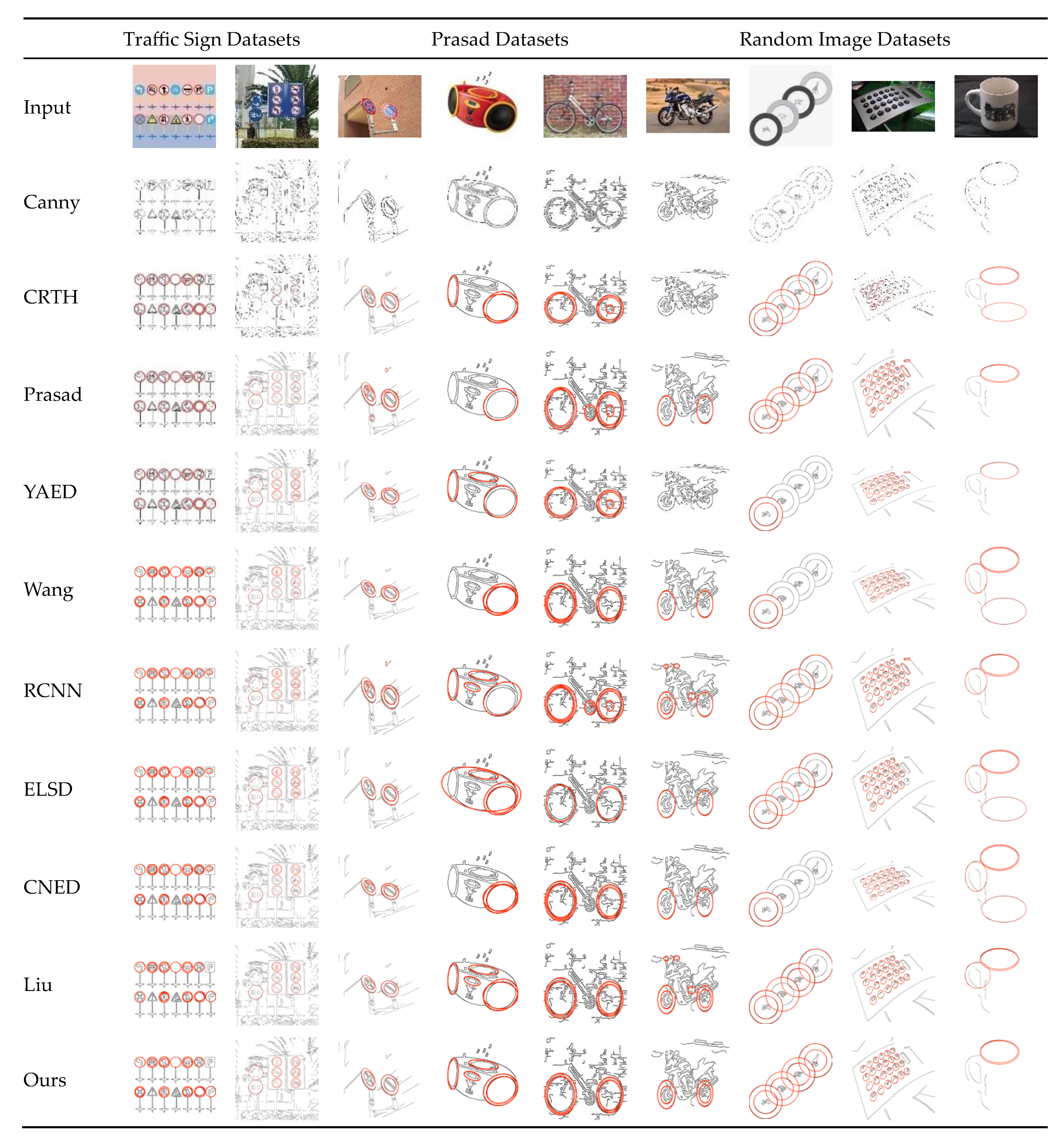
Results from the images of the three datasets are shown in
Figure 7. First row: original image; second row: adaptive Canny edges; third row: CRHT result; fourth row: Prasad result; fifth row: YAED result; sixth row: Wang result; seventh row: RCNN result; eighth row: ELSD result; ninth row: Liu and Qiao result. In rows three to nine, red indicates detected ellipses and black indicates Canny edges.
A change rate is defined, and the performance indicators will change as it changes. Specifically, a detected ellipse is regarded as true positive if its ratio of overlap area to the corresponding ground true ellipse is greater than 0.8 [
27,
29,
56]. The overlap ratio (OR) calculation proposed by Prasad [
56] is as follows:
where
and
are, respectively, the ground truth and detected ellipse, and
and
are the non-overlapping and overlapping areas. In addition, we evaluated the speed of the proposed method in terms of detection time using the three datasets.
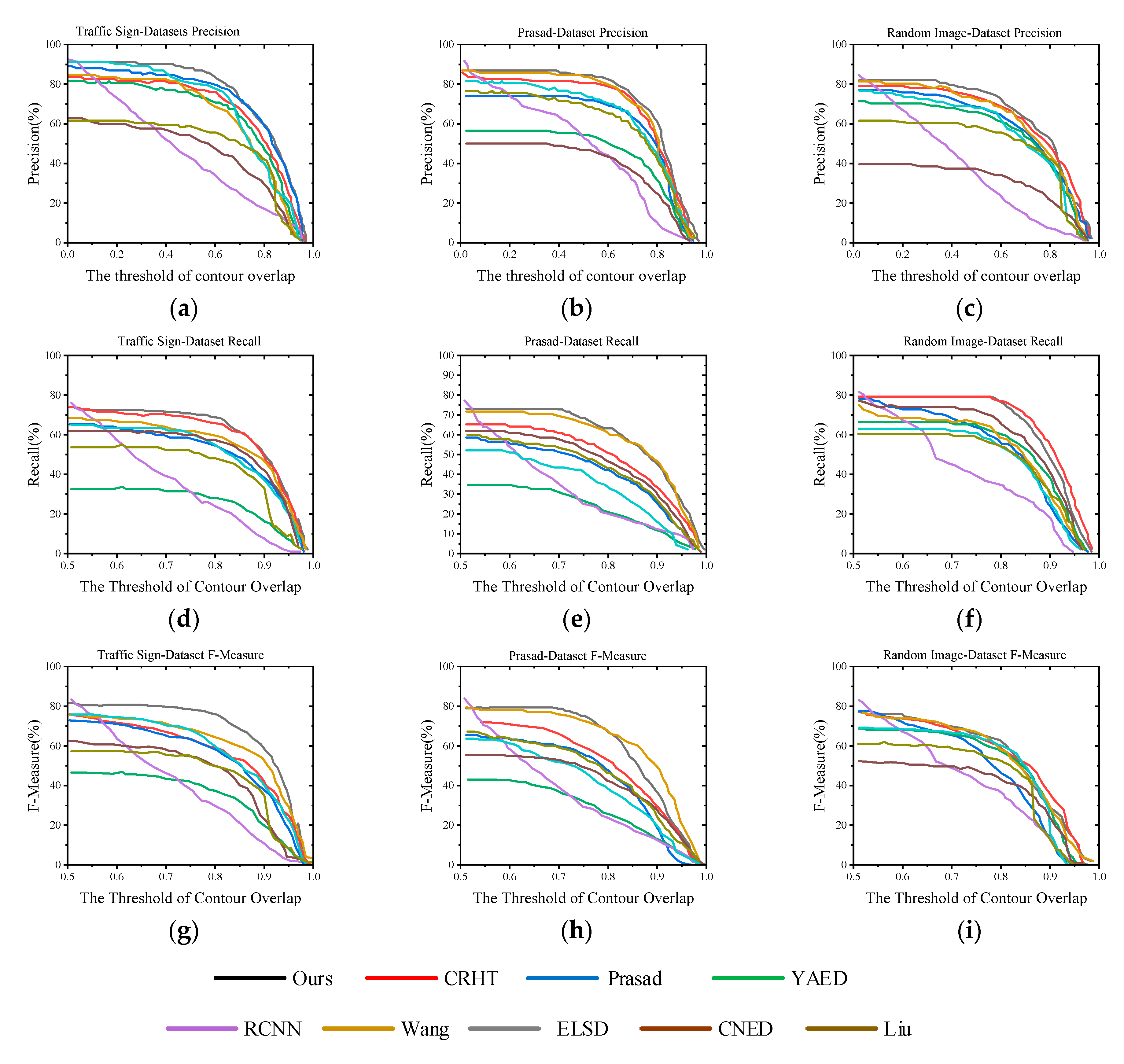
The detection results of the three real datasets are shown in
Figure 7, and the corresponding algorithm performance statistics are shown in
Figure 8. The Liu and CRHT methods do not use convexity and curvature to divide the edge contour into elliptical arcs, thus did not perform well on real images. Prasad’s method had a good recall rate, but did not effectively eliminate false ellipses, resulting in low accuracy. ELSD had a good performance, and detected more small ellipses on the Prasad dataset. However, ELSD only detected elliptical arcs without arc grouping, leading to low performance on random images. YAED provides a novel grouping and verification method to remove wrong ellipses, but it did not perform well on images with complex backgrounds. Wang’s method can detect more positive ellipses, but it still had more wrong results than ours. CNED uses the idea of point set registration to match the ellipse model with the edge points to get the ellipse parameters, but it is sensitive to useless edge points and is not suitable for images with complex background. CNED greatly improves the detection accuracy based on YAED. The method of Liu et al. had a better recall rate than most methods, but its accuracy was lower than that of Wang et al. and ours. RCNN is a novel framework for detecting general objects. It has been proved that deep learning can detect ellipses, but it depends heavily on the selection of previous datasets. The performance of each dataset can be summarized as follows:
Our method performed best on the traffic sign dataset, with high accuracy, recall rate, and F-measure score. In addition to the recall rate, our method temporarily led on CRHT when OR was <0.55. Later, with a change of OR, our method again scored the highest, with leading accuracy and F-measure values. ELSD had a better F-measure score. In addition, the RCNN machine learning method performed better in the early stage, when OR was less than 0.55, but it was unstable. With a change of OR, it decreased faster, and the performance was worse in the later stage.
The Prasad dataset was mainly used to test the detection performance of various algorithms on overlapping, concentric, and concurrent ellipses, and we found that the performance of our algorithm was the most stable. In terms of accuracy, the method proposed by Wang et al. and our method showed their advantages after OR > 0.6, with a difference of only 0.11% between them. In terms of recall rate, with 0.83 < OR < 0.93, Wang’s method had a slight advantage, and our method scored higher. In terms of F-measure, our method scored higher when OR was less than 0.78, and Wang’s method scored higher and had better stability when OR was more than 0.78. The RCNN performance throughout the day was the same as the accuracy score, which was unstable and decreased faster with the change of OR.
Our algorithm had the best accuracy on occluded ellipses, but the recall rate was slightly lower than CRHT after OR > 0.8, and F-measure had a better score. Specifically, in terms of accuracy, our method ranked first overall, followed by Wang’s method, but it was unstable. When OR > 0.84, our method fell behind slightly. In terms of recall rate, CRHT was basically at the same level when OR < 0.8, with a difference of 0.15%; when OR > 0.8, CRHT had more advantages, but it was not significant on tracking tasks. In terms of F-measure score, our method is not much different from Wang’s, CRHT, and ELSD when 0.6 < OR < 0.75; when OR > 0.85, our method was slightly behind.
In general, our method performed best on the traffic signs and random image datasets, and ranked second on the Prasad image dataset. The F-measure score was slightly lower than Wang’s method when OR > 0.8. In general, our method was superior to the other methods in terms of recall rate, precision, and F-measure.
4.4. Performance and Efficiency Analysis
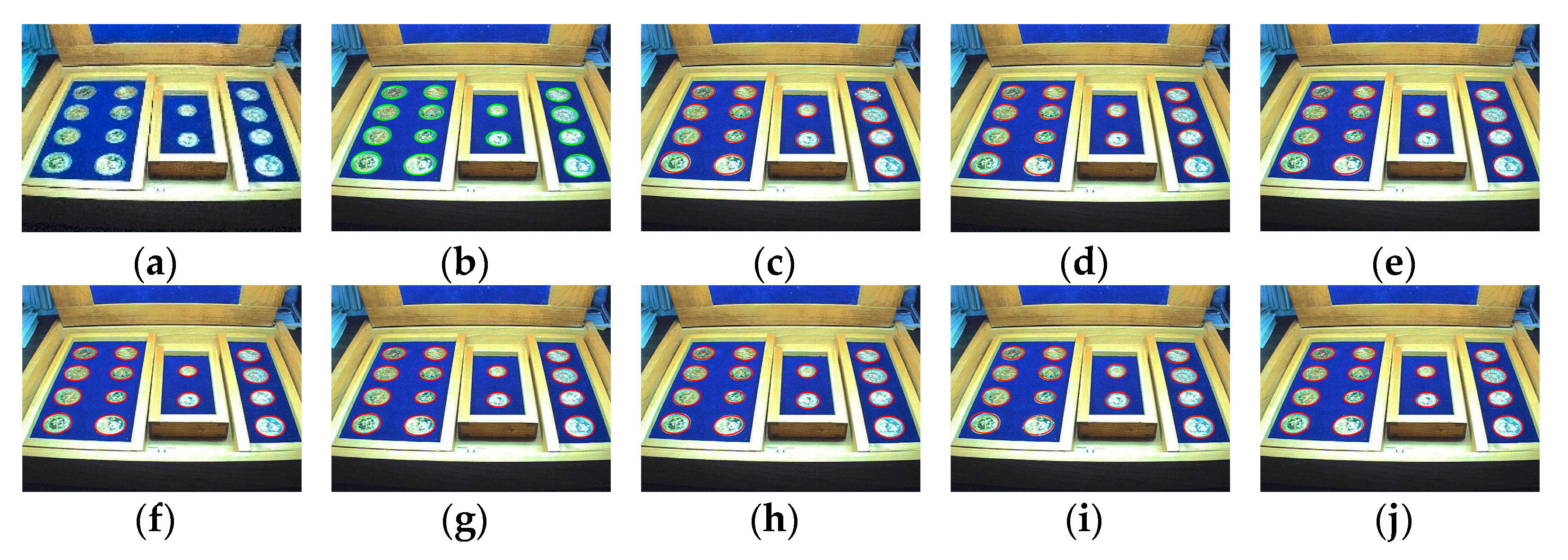
We selected a representative image in the Prasad database (image 043_0045) as a candidate to test the performance of CRHT, Prasad, ELSD, YAED, Wang, RCNN, CNED, Liu and Qiao, and our proposed method, especially in a real-time comparison. The ellipse is arranged from near to far, and there are various angles of the ellipse, which is suitable for testing the performance of ellipse detection algorithms. The detection results are shown in
Figure 9.
The detection of ellipses in pictures in the Prasad dataset, is shown in
Figure 9. The same performance indicators were used to calculate the consumption time and detection performance of a single picture frame, as shown in
Table 2. In the processing of this frame, the accuracy of our proposed method was slightly lower (1.33% lower) than the best-performing ELSD. In terms of recall rate, CRHT showed the best performance, 3.76% higher than our method. In terms of F-measure score, our method performed the best, 7.75% higher than ELSD, with obvious advantages. More importantly, in terms of time consumption, our method only needed 0.0252 s, which is preferable compared to other methods, especially ELSD, with the highest accuracy score and the second-highest F-measure score, which consumed more time. After analysis, we know that this method consumes the most time in the process of ellipse segmentation, and this will reduce the real-time performance of the algorithm. Our method significantly reduces the time for grouping and fitting steps, and further improves the overall detection speed. Although our method sacrifices accuracy, it qualifies as a real-time ellipse detection method for application in robots.
4.5. Real-World Testing
In order to test the performance of the proposed ellipse detection and tracking method, it was compared with those methods mentioned in
Section 4.3. When the robot operates in the field, especially in the relatively dark environment (overcast, dusk or evening), the lack of light will have a great impact on the images collected by the shooting equipment, resulting in a serious decline in the recognition rate based on visual methods. Specifically, when the light is weak, the overall gray value of the corresponding collected image is low; When the light is strong, the gray value is higher. All the algorithms mentioned above extract edge information after graying, and strong or weak illumination will affect the algorithm. The ellipse detection algorithm proposed in this paper will have the possibility of target loss if the light is strong or weak. However, the combined tracking algorithm can continuously maintain the detection of elliptical targets under the premise of small motion changes of the robot, which can reduce many restrictions of the environment on the algorithm and adapt to the robust detection of ellipses under natural light conditions. A UAV was used to test autonomous landing on a two-dimensional nested ring circular pattern on top of a mobile platform in indoor and outdoor practical application environments.
We eventually ran a sixth set of experiments to evaluate the performance of the detectors on natural video that presented various common challenges: reduced resolution, complex geometric primitives, background clutter, partially blocked areas, and limited sensor distance. This evaluation is given only qualitatively, because establishing the necessary reliable ground truth for the quantitative evaluation of arbitrary natural images is far from trivial. We illustrate typical scenes of the detectors by means of examples. In the indoor scene, simulate the weak light environment without interference. In the outdoor experiment, in addition to the change of light, there are other interferences, such as wind and electromagnetic interference.
- (1)
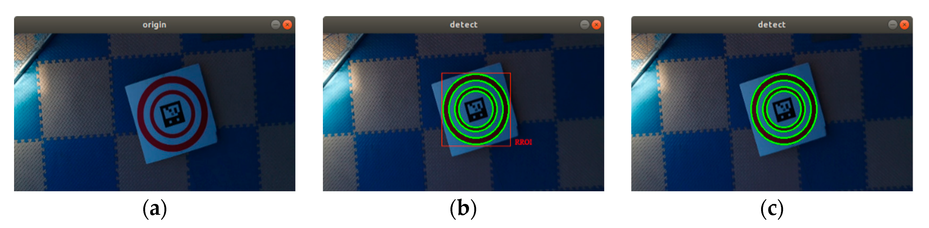
Indoor low-light scene
In the room, before the sun set in the afternoon, we turned off the lights and closed the curtains, simulating only a weak light environment. At this time, any light present is mainly leaking from the gap in the curtain when it moves due to the effects of UAV blade rotation but no other interference, such as wind, electromagnetic interference, etc. The detection effect is shown in
Figure 10. The detection and tracking effect was good, and four ellipses could be detected completely and their parameters estimated.
- (2)
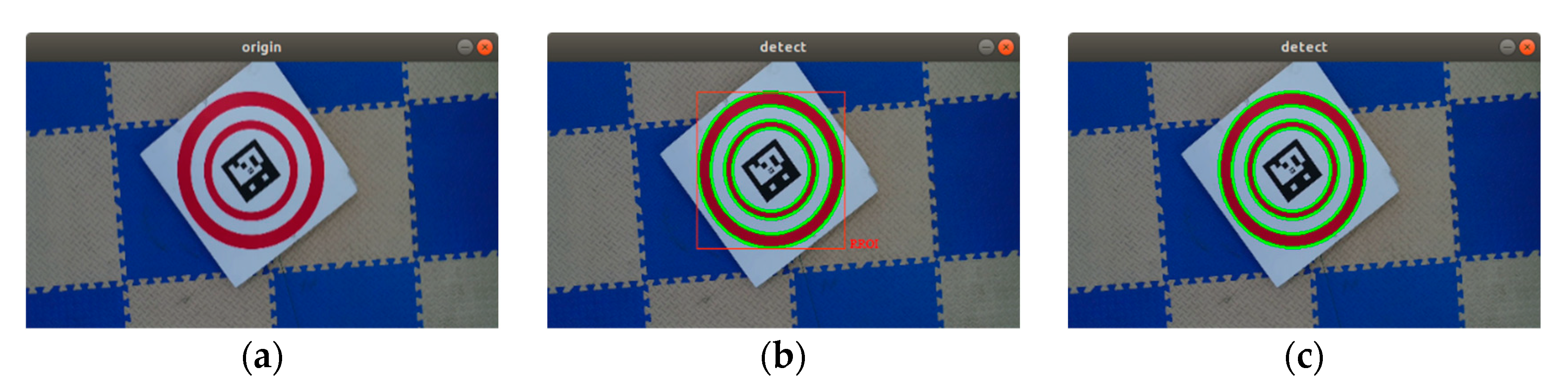
Indoor bright environment
In the room, fluorescent lamps could be turned on at night, and the curtains could be closed to obtain a bright lighting condition. The detection effect at this time, when the illumination is good, is shown in
Figure 11. The detection and tracking effect was good, and four ellipses could be detected completely and their parameters estimated.
- (3)
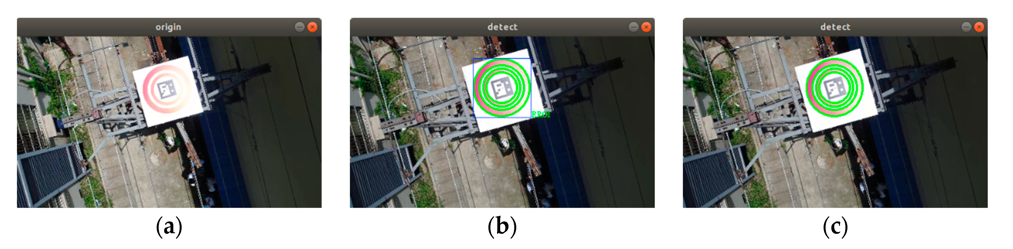
Outdoor bright environment
Although a landing plate made of low-scattering matte material was used, there was still obvious reflection at noon in sunny weather, as shown in
Figure 12. At this time, the oval red circle had some information mixed with the white background, and our algorithm still showed good detection performance, as it could accurately detect the ellipse and estimate its parameters.
- (4)
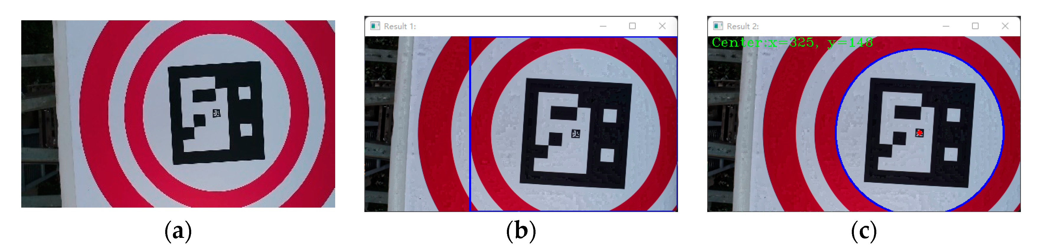
Outdoor low light and shelter environment.
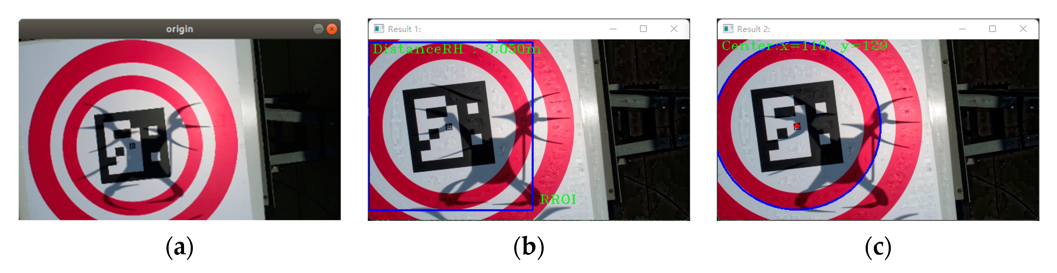
In outdoor low light, the elliptical target was close to the camera, and there were only partial elliptical arcs in the field of view, as shown in
Figure 13. When the elliptical target was close to the camera sensor, there may have been some elliptical information in the field of vision. Using our algorithm, we could detect the RROI and estimate the elliptical parameters.
- (5)
Outdoor shadow and occlusion environment
When the UAV was flown at noon, both its body and propeller cast shadows on the landing plate and added stray information, as shown in
Figure 14. Using the proposed algorithm, the RROI was determined in the HSV color space, the ellipse was quickly detected, and the ellipse parameters were estimated, thus it could be used for real-time autonomous landing of UAVs.
At the same time, it was found in the experiment that the solution of image upsampling could detect more small ellipses, but with increased upsampling scale, the increase in effective detection rate became smaller and smaller. The reason is that there was much noise and many uneven curves on the edge of the upsampling image, resulting in oversegmentation and arc detection failure.
- (6)
Specific height test in low light
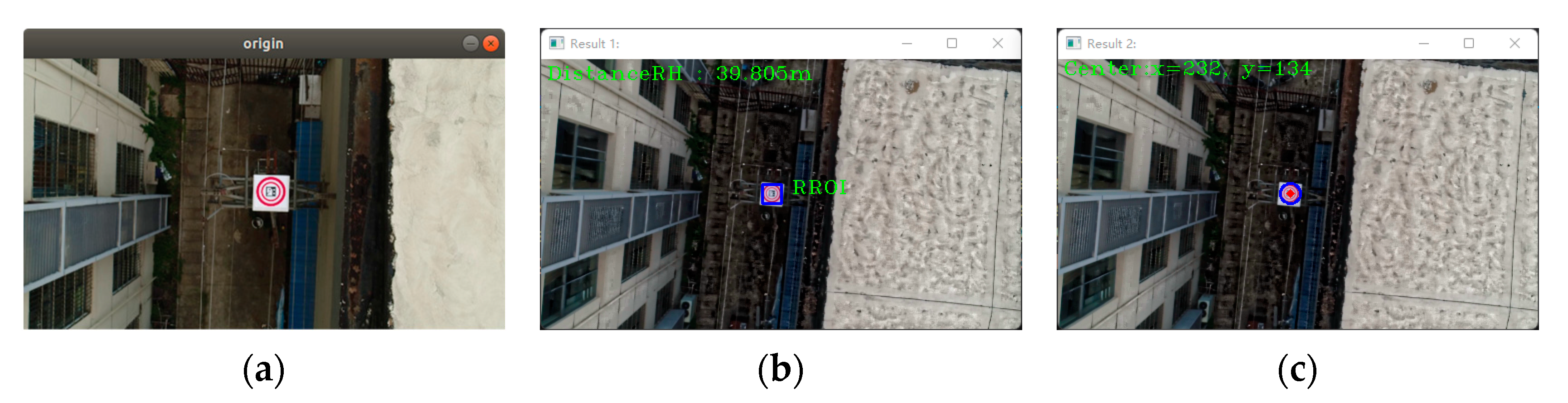
A low-cost consumer-grade USB camera was used at a distance of 40 m from the target, which was small at only 56 × 56 pixels, as shown in
Figure 15. It is extremely challenging to detect elliptical targets in dim light. Using the proposed algorithm, the RROI could be determined at 39.805 m, thus the ellipse could be detected and its parameters estimated.
These scenarios are extreme environments in which robots are applied under natural light conditions. They cover all the possibilities that robots can encounter on cloudy days, sunny days, noon, dusk or evening. The specific quantification of the illumination change is the loss and accuracy of the detection target. The weaker the illumination intensity is, the smaller the gray value of the image is, and the stronger the illumination intensity is, the larger the gray value of the image is, both of which will lead to the loss of the target information and cause detection error. The tracking algorithm in this paper effectively eliminates the two extreme situations, and uses the robot micro motion and the high real-time ellipse detection algorithm to ensure that the landing of the UAV is not affected by the change of light.
4.6. Performance in Real Scenes
Under conditions of real natural light, the performance of the proposed algorithm in the real application was comprehensively evaluated by the average performance index in each scenario described in
Section 4.5, as shown in
Figure 16.
The performance of the ellipse detection algorithm described in
Section 4.3 was tested in real scenarios. The statistics show that our method had a leading advantage in practical application scenarios; it could detect elliptical targets in real time in the presence of shadows or large changes in illumination, at long distances, and in indoor and outdoor environments. Specifically, in terms of accuracy, our method reached more than 90%, which is superior to the other methods. ELSD ranked second, with a lead of more than 2%. In terms of recall rate, our method reached 89%, 0.4% higher than ELSD. In terms of F-measure, our method scored 90.9%, the only method that scored more than 90%. In terms of time consumption, under the same experimental conditions, the average time of our method was 38.65 ms, which was better than the other methods. Running on the on-board computer, it could meet the real-time requirements of robot applications.
4.7. Discussion
The performance test data of the traffic sign, Prasad, and random picture datasets, and real application scenarios are shown in
Table 2 and
Figure 15. The proposed method was compared with several mainstream methods. The UAV was selected as the test platform and the algorithm was run on a lightweight portable DJI Manifold 2 on-board computer. CRHT [
22], Prasad [
56], and Liu [
40] were run in MATLAB, while ELSD [
26], YAED [
27], Wang [
28], CNED [
29], and our proposed method was implemented in C++; the execution efficiency of the latter is much higher than the former. In the process of public dataset testing, the accuracy, recall rate, F-measure score, and processing time of a single image frame were comprehensively evaluated. In terms of accuracy, our method performed better than the other methods, except for the Prasad dataset, which was slightly lower than Wang’s method. In terms of recall rate, with a change of OR, the performance on the three datasets differed, but the difference between the best method and the next best method was small. In terms of F-measure, our method showed good advantages on the three datasets. The dataset test showed that the proposed method could achieve better detection results, especially on the traffic sign and random image datasets. In terms of processing time, testing on the Prasad real scene dataset showed that the proposed method can meet the real-time detection requirements of robots.
In the actual application scenarios, the mentioned methods and our method were superior to the comparison methods in terms of accuracy, recall rate, F-measure, and consumption time based on a comparison of the average performance index scores under indoor and outdoor, natural environment, partial object occlusion, and long-distance conditions. When the robot was approaching the target mode, the speed of our method was significantly improved (frame processing time decreased to only a few milliseconds). When a robot needs faster processing speed to approach a moving landing platform, an improvement in this speed is especially helpful for the system to have a higher detection rate.
Based on the HSV color space, we used the prior color information to accurately determine the region of interest, extract all contours, solve the eigenvectors of the eigensystem, and fit all contours through the non-iterative ellipse fitting algorithm. Next, we tested the fitting degree of the estimated ellipse and contour, and set up mechanisms to filter the contour. The remaining contour after the screening was identified as the ellipse to be detected. During this process, if there are no remaining contours (for example, no ellipse data in the current frame), the algorithm will return a set of empty ellipses. Combined with a simple tracking algorithm, the method can significantly improve the accuracy and performance of ellipse pattern detection by properly changing the parameters of the algorithm. In addition, after adopting the simple tracking algorithm, the tracking loss is effectively reduced in the process of operation, and it has been proved that this is faster than using a predictive filter. At the same time, when the detected object is in the field of view, the clustering method is used to eliminate the influence of the stray contour on the detection results and effectively eliminate the stray arc. The proposed method performed well on the test dataset; however, it has some disadvantages:
- (1)
Regarding the prior information of color in HSV color space, there is a risk of false detection when the color is similar to the detected target.
- (2)
With a complex background, the edge contour can be divided into many elliptical arcs, and it can take a lot of time to verify the candidate combination.
- (3)
It cannot effectively control small ellipses. When the target is far from the camera, the edge contour of a small ellipse will cause a failure to detect the elliptical target.
- (4)
In images with more ellipses, the recall rate will be lower.
There are some efficient methods in the experiment for improvement in light of the shortcomings mentioned above:
- (1)
When the colors are similar, a range that is larger and contains all colors can be selected, filtering out pointless contours by imposing some restrictions.
- (2)
The algorithm will over-discover contours on complex backgrounds, decreasing the accuracy of the detection. The connection between frames can be used to reduce the sampling frequency, and the fixed contour tracking function can be added to the tracking algorithm to eliminate other contour interference.
- (3)
A higher pixel high definition (HD) camera can be used for testing when the target is too far from the camera and the target detection fails.
- (4)
In order to guarantee detection accuracy, it is not required to pay too much attention to the recall scores when the image contains more ellipses.
As a result of the discussion above, the following areas of this study can be the subject of further research:
- (1)
To further enhance the real-time performance of ellipse detection, a more straightforward and practical tracking approach is devised.
- (2)
Reduce the complexity of the algorithm further and expand its support for more low-cost embedded controllers.
5. Conclusions
In this paper, we proposed a fast, high-precision, robust ellipse detection method that employs an effective arc extraction algorithm and a candidate selection strategy. We have made innovative improvements on account of the existing methods. The method combined with a simple tracking algorithm requires only approximately 30 ms in most cases, while achieving very good detection performance. The performance of the method is mainly guaranteed by (a) accurate contour recognition in HSV color space; (b) effective arc selection and grouping strategies that eliminate numerous invalid edges and groups; and (c) the candidate ellipse selection strategy that realizes both validation and de-redundancy (clustering) functions. Extensive experiments are conducted to adjust and verify the method parameters for achieving the best performance. The results show that the proposed method has the best performance (precision, recall, F-Measure scores) and the least execution time compared with the other nine most advanced methods on three public actual application datasets. In practical application scenarios, our method can detect elliptical markers online and in real-time. The ellipse can be well detected when the elliptical object is far from or close to the robot. Severely blocked ellipses can still be detected. Meanwhile, the method can adapt to detect ellipses under natural light. When there is specular reflection, the robot can detect elliptical markers. The average detection frequency can meet the real-time requirements (>10 Hz). Therefore, our method can be widely used in smart cities and smart buildings, including the autonomous landing of UAV express delivery or construction material transportation in smart buildings, the identification of UAV charging base stations, and the identification and tracking of elliptical objects in smart cities.
In the future, we will improve our method to make it possible to be widely used in the detection of extremely small ellipses and half-baked ellipse in images of robots, especially in the hardware and software of video stream processing applications, which is a challenge for most existing methods. The following suggestions could further improve the performance and increase the availability of this method in practical robot applications:
(1) The basic algorithm used in the ellipse detection step is the most commonly used method in the OpenCV library. If better performance is needed, the execution speed and performance of the whole method could be improved by replacing the steps of ellipse fitting with faster and better algorithms.
(2) If the robot’s camera is not perfectly calibrated or has large distortion, it may lose tracking of elliptical targets at close range. In this case, only a small part of the pattern is visible at an oblique angle, resulting in the circle being considered non-elliptical by the camera. Of course, any ellipse detection algorithm has this problem. To improve the detection performance when the robot’s camera is too close to the ellipse pattern, a robust tracker (such as a redundant pattern calibrator or correlation discrimination filter) can be used instead of tracking the target ellipse through the detector.


