Article

Multi-UAV Trajectory Planning during Cooperative Tracking Based on a Fusion Algorithm Integrating MPC and Standoff

1
School of Electronics and Information, Northwestern Polytechnical University, Xi’an 710072, China
2
Xi’an Electronic Engineering Research Institute, Xi’an 710100, China
3
School of Robotic and Intelligent Systems, Moscow Aviation Institute, 125993 Moscow, Russia
*
Author to whom correspondence should be addressed.
Drones 2023, 7(3), 196; https://doi.org/10.3390/drones7030196
Submission received: 10 February 2023 / Revised: 5 March 2023 / Accepted: 9 March 2023 / Published: 14 March 2023
(This article belongs to the Special Issue UAV-Assisted Intelligent Vehicular Networks)

Abstract

:
In this paper, an intelligent algorithm integrating model predictive control and Standoff algorithm is proposed to solve trajectory planning that UAVs may face while tracking a moving target cooperatively in a complex three-dimensional environment. A fusion model using model predictive control and Standoff algorithm is thus constructed to ensure trajectory planning and formation maintenance, maximizing UAV sensors’ detection range while minimizing target loss probability. Meanwhile, with this model, a fully connected communication topology is used to complete the UAV communication, multi-UAV formation can be reconfigured and planned at the minimum cost, keeping off deficiency in avoiding real-time obstacles facing the Standoff algorithm. Simulation validation suggests that the fusion algorithm proves to be more capable of maintaining UAVs in stable formation and detecting the target, compared with the model predictive control algorithm alone, in the process of tracking the moving target in a complex 3D environment.

1. Introduction

The increasingly complex mission environment in recent years has given UAVs their favored market, seeing them widely used for reconnaissance and monitoring missions due to their low cost, high autonomy and reusability [1,2]. Tracking a moving target, whether for single or cooperative tacking, is a significant sub-problem for UAVs performing monitoring tasks. Yet, a single UAV can hardly meet its actual task requirements as it works on its own [3,4], because its sensor’s range of view may be easily blocked and therefore its ability to accomplish tasks limited. Cooperation of several UAVs, however, helps make target tracking and monitoring easier. Cooperative efforts made by UAVs can reduce the risk of target loss [5,6], and ensure the accomplishment of a task with multi-sensor data fusion, which means multi-UAV collaboration used in trajectory planning for moving target tracking purposes.
At present, multi-UAV collaborative planning mainly involves artificial potential field method [7,8], bionic algorithm and control algorithm. When the artificial potential field method is applied to the collaborative planning process, it is easy to fall into local optimality and difficult to establish a complete mathematical model. Bionic algorithms, which mainly include ant colony algorithms [9], and particle swarm algorithms [10], also prove to be challenging to meet the real-time demand due to their limited processing efficiency. Control algorithms mainly cover PID control [11], optimal control [12], H-infinity robust control [13], sliding mode control [14], and model predictive control [15,16], etc. Most of these algorithms, such as PID control, optimal control, H-infinity robust control and sliding mode control, are not suitable for complex variable control problems such as cooperative planning of multiple UAVs given their limited control variables and application scenarios that appear quite poor, while the model predictive control algorithm, as the only control method that can explicitly handle constraints at present, has leveled itself up to the acknowledged standard for handling complex constrained variable control problems. It adopts a form of rolling optimization and feedback correction, i.e., the predicted trajectory will be corrected online at each sampling cycle. With strong anti-interference ability and strong robustness, it has attracted widespread attention from scholars at home and abroad. Animesh Sahu [17] and others conducted a study on multi-UAV tracking of multiple moving targets in two dimensions based on the model predictive control algorithm and developed a data-driven Gaussian process (GP) based model that relates the hyperparameters used in model predictive control to mission efficiency. Marc Ille [18] and others carried out research on multi-UAV formation collision avoidance in two-dimensional environments based on the model predictive control algorithm, optimized model predictive control cost functions using penalty term methods, and controlled UAVs’ track planning as they tracked a moving target based on formation avoidance constraints. However, relevant research on [17,18] UAV formation control is rare. Tagir Z. Muslimov [19] and others proposed a method based on the Lyapunov vector field for multi-UAV cooperative tracking of the moving target in a two-dimensional environment. The method is grounded around dispersed guided Lyapunov vector fields for path planning. Based on the two-dimensional environment, Q. Guo [20] and others proposed a performance guaranteed 5 1 3 -approximation algorithm for the UAV scheduling problem when ignoring the limited flying time of each UAV, such that the maximum spent time of UAVs in their flyingtours is minimized. A fusion algorithm for adaptive multi-model traceless Kalman particle filter was adopted by Niu Yifeng [21] and others to carry out a study on coordinated tracking of ground multi-target trajectory for UAV swarms in complex two-dimensional environments. A pioneering exploration is Zhang Yi [22] and others who solved the problems regarding non-convergence of initial heading and long phase coordination time among UAVs in the process of cooperatively tracking a moving target based on Standoff method, following which Zhu Qian [23] and his team also studied two aircrafts’ cooperative tracking of a moving target by means of angle measurement.
A comprehensive analysis of the above research found that most of the current research on multi-UAV trajectory planning through cooperative formation stays in two-dimensional space, still challenged by problems such as large model calculation and insufficient real-time. At the same time, the current research faces great difficulty in establishing a complete non-linear UAV 3D motion model, and thus fails to meet actual mission requirements [24]. As for traditional multi-UAV sensors, their limited detection coverage as well as weak formation and retention capabilities [25] prevent them from being the hot spot in this field, leaving UAV trajectory planning that integrates collision avoidance and obstacle avoidance not fully explored.
Against such a background, this paper proposes a fusion algorithm that combines the model predictive control algorithm [26] and the Standoff algorithm. The model predictive control algorithm solves the problem of large-scale real-time optimal control in limited time [27] and uses the preview capability to achieve optimal maneuver control in a constrained, non-linear, model-uncertain and unpredictable environment to generate smooth flyable paths suitable for the actual flight of the formation [28]. The Standoff algorithm [29], one of the main algorithms for formation control, maximizes sensor detection range and reduces the probability of target loss with safe distances as grounds [30]. Compared with the traditional multi-UAV cooperative trajectory planning method, the fusion algorithm simplifies the mathematical modelling of UAVs’ three-dimensional motion [31], reduces the computational complexity which is caused by strong non-linearity as defined in the dynamics [32], and enhances real-time performance that an algorithm can show compared with the two papers [33,34]. It integrates the maximization of the sensor’s observation coverage to establish UAV sensors’ monitoring model, and more importantly, reduces the probability that UAVs lose their moving target compared with the sensor detection model proposed by the thesis [35]; Inspired by the minimum long-term operational cost suggested by the paper [36], the present study designs the reconfiguration planning of UAV formation at the minimum cost. As the distributed learning principle reported in the research [37] indicates, it constructs a multi-UAV track planning model using a distributed model predictive control algorithm to transform the challenge of centralized UAV formation mentioned in the paper [38] into that of a distributed flight control optimization, verifying the effectiveness of the fusion algorithm by means of unexpected artificially implanted obstacles.
The remainder of this paper is as follows: Section 2 introduces the trajectory planning model that UAVs take while they cooperatively track the moving target in a complex three-dimensional environment, followed by how it is configured and designed based on the fusion algorithm in Section 3, in addition to the cooperative formation reconfiguration and planning when an unexpected situation occurs to the vehicles. Simulation validation is carried out in Section 4 to demonstrate the effectiveness of the fusion algorithm applied to multi-UAV collaborative tracking of moving target trajectory planning. The following section conducts a study on the effectiveness and monitoring capability of multiple UAVs in coordinated formation to track moving targets, and illustrates that the fusion algorithm has better tracking effectiveness and monitoring capability in the test, while the last section offers a conclusion.

2. UAV Model and Environment Model

2.1. UAV Motion Model

Different from most of the previous literature that used the two-dimensional plane to establish the motion model of the UAV, this paper regards the UAV as a mass point and builds a three-dimensional motion model based on the inertial reference system without considering the influence of external disturbances, noise and air resistance on the UAV dynamics, and carries out discretization processing on it. Assuming that the sampling time is t , the UAV motion model is expressed as Equation (1).
x ( k + 1 ) = x ( k ) + v ( k ) cos θ ( k ) sin φ ( k ) Δ t y ( k + 1 ) = y ( k ) + v ( k ) cos θ ( k ) cos φ ( k ) Δ t z ( k + 1 ) = z ( k ) + v ( k ) sin θ ( k ) Δ t v ( k + 1 ) = v ( k ) + a ( k + 1 ) Δ t φ ( k + 1 ) = φ ( k ) + φ ˙ ( k + 1 ) Δ t θ ( k + 1 ) = θ ( k ) + θ ˙ ( k + 1 ) Δ t s ( k ) = [ x ( k ) , y ( k ) , z ( k ) ] S u ( k ) = [ v ( k ) , φ ( k ) , θ ( k ) ] U
where s ( k ) denotes the UAV state sampling at time k ; S denotes the feasible state set; u ( k ) denotes the control input of the UAV at time k ; U denotes the feasible input set; ( x ( k ) , y ( k ) , z ( k ) ) is the real time position of the UAV; v ( k ) , φ ( k ) and θ ( k ) denote the real time speed, heading angle and pitch angle of the UAV respectively, and a dotes the acceleration of the UAV.

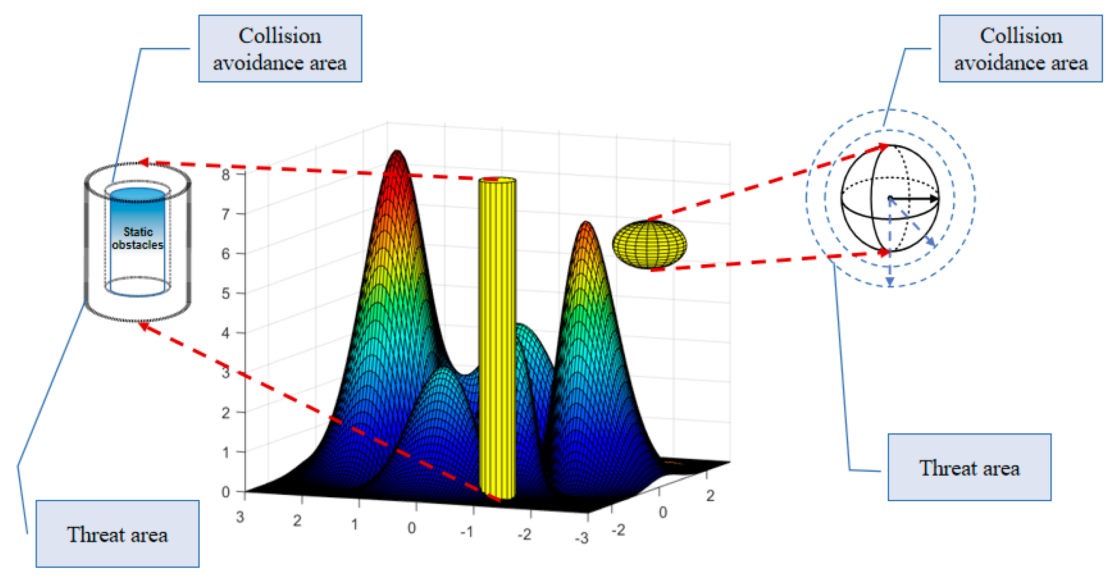
2.2. UAV Collision Avoidance Model

Since UAVs need to fly as ultra-low as possible in order to avoid radar detection, the complex ground environment and its obstacles become the primary threat to UAV trajectory planning. This paper creates a map model based on undulating terrain topography to fulfill the actual task requirements, as shown in Figure 1. To improve the robustness of the method, a safety buffer zone is established around the UAV, and the obstacles are divided into static obstacle modelling and emergent obstacles. The static obstacle model is approximated by a cylinder whose co-ordinate center is set to P o , whose co-ordinates are [ P o x , P o y ] , and whose radius and height are denoted by P o r and P o z . A collision zone (denoted by L o d and H o d ) and a threat zone (denoted by L O D and H O D ) are established around it. L o d is the minimum proximity safety distance while H o d is the minimum height proximity distance, and if the distance between the UAV and the static obstacle is less than L o d and H o d , the UAV will collide. L O D and H O D are the maximum threat distance of the static obstacle, and if the distance between the UAV and the static obstacle is less than L O D and H O D , the UAV may have the risk of collision. The sudden obstacle model is approximated by a sphere, the centre of which is set to P t , with specific coordinates [ P t x , P t y , P t z ] and a radius of R t . The collision zone (represented by a sphere with a radius of R p ) and the threat zone (represented by a sphere with a radius of R w ) are also set up, and the specific UAV collision avoidance and collision avoidance model is shown in Equation (2).
z i ( k ) z a l l ( k ) > Δ H d x i ( k ) , y i ( k ) , z i ( k ) x j ( k ) , y j ( k ) , z j ( k ) 2 R a ( x i ( k ) P t x ) 2 + ( y i ( k ) P t y ) 2 + ( z i ( k ) P t z ) 2 R w ( x i ( k ) P o x ) 2 + ( y i ( k ) P o y ) 2 L O D       o r       z i ( k ) P o z Δ H O D
where ( x i ( k ) , y i ( k ) , z i ( k ) ) denotes the current UAV position coordinates; R a denotes the UAV minimum collision avoidance safety distance; ( x j ( k ) , y j ( k ) , z j ( k ) ) denotes the adjacent UAV position coordinates; z a l l ( k ) denotes the height of the ground coordinates ( x i ( k ) , y i ( k ) ) ; and H d denotes the UAV near-ground minimum safety distance.

2.3. Moving Target Model

The establishment of a rationalized moving target motion model is the prerequisite for the successful track planning of UAVs when they cooperatively track the moving target. This paper defines the target motion model as Equation (3). To simplify the operation, the moving target’s trajectory is compressed from the three-dimensional space to the two-dimensional y o z plane, i.e., the x coordinate of the moving target is set to a constant value.
x ˙ u ( k ) y ˙ u ( k ) z ˙ u ( k ) v ˙ u ( k ) θ ˙ u ( k ) φ ˙ u ( k ) = v u ( k ) cos θ u ( k ) sin φ u ( k ) v u ( k ) cos θ u ( k ) cos φ u ( k ) v u ( k ) sin θ u ( k ) g sin θ u ( k ) g cos θ u ( k ) v u ( k ) 0 + 0 0 0 0 0 0 0 0 0 1 0 0 0 1 v u ( k ) 0 0 0 1 v u ( k ) cos θ u ( k ) a 1 a 2 a 3
where v u ( k ) denotes the velocity of the moving target at k , θ u ( k ) denotes the pitch angle of the moving target, φ u ( k ) denotes the heading angle of the moving target ( φ u ( k ) = 0 ), g is the acceleration of gravity, a 1 denotes the horizontal acceleration of the moving target, a 2 denotes the vertical acceleration of the moving target and a 3 denotes the angular acceleration of the moving target, and the motion constraint of the target can be completed by adjusting according to parameter a = [ a 1 , a 2 , a 3 ] .

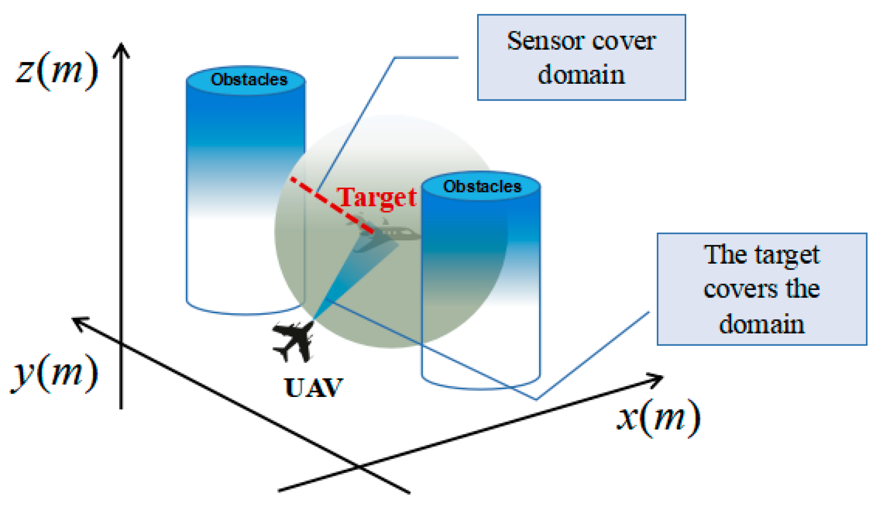
2.4. Target Observation Coverage Modelling

The modeling of target observation coverage is based on the UAV sensors. In this paper, the mathematical modeling of target observation coverage is based on four factors: P f , P w , L m a x and L m i n . P f indicates the probability that the sensor detects the target effectively, P w indicates the probability that the sensor detects the target incorrectly, and P f , P w ( 0.1 ] . L m a x indicates the maximum detection distance of the sensor, and L m i n indicates the effective distance that the sensor detects completely. When the distance between the sensor and the target is less than L m i n , P f = 1 . Given the influence of multiple obstacles encountered during UAV trajectory planning, it does not meet the actual needs to only use the maximum detection distance of the sensor as the measurement standard. Based on this, this paper defines that the UAV is only likely to detect a target when the target enters an area where it can be seen by the vehicle, and the sensor is only capable of detecting the target when the target is within its coverage. The intersection of the area where the target is visible and the sensor’s coverage area is defined as the target observation coverage, which circumvents the obstruction of the UAV’s line of sight by environmental obstacles and ensures effective monitoring of the moving target by multiple UAVs in formation, as shown in Figure 2, whose discretization modelling is expressed as Equation (4). Define the effective detection range of UAV sensors and the radius of the target coverage area to be the same, both of which are L m i n = 40   m . The UAV can monitor the moving target when it is within the sensor’s detection range.
p ( L t ) = 1 L t < L min p f ( p f p w ) ( L t L min ) L max L min L min < L t < L max p w L t > L max
where P ( L t ) denotes the probability of the sensor effectively monitoring the target and L t denotes the real-time distance between the UAV sensor and the target.

3. Designing a Multi-UAV Cooperative Tracking System Based on the Fusion Algorithm

3.1. System Design

After each UAV receives the tracking task, it initializes the system model according to the prior obstacle information, target movement information and its own motion information. In view of constraints such as obstacle avoidance and collision avoidance, the model predictive control algorithm is used to predict the trajectory of multiple UAVs at the minimum planning cost. In terms of formation and maintenance of multi-UAV formation, the Standoff algorithm is used to complete the multi-UAV formation control, so that the UAV swarm is evenly distributed around the target, and then multi-UAV sensors can maximize the monitoring of the moving target. The specific system framework is shown in Figure 3. The cooperative collision avoidance control module is mainly responsible for obstacle collision avoidance and inter-UAV collision avoidance, taking into account the UAV motion state, obstacle information, map boundaries and other factors to plan a safe and collision-free flight path. The model prediction control module is responsible for predicting the UAV trajectory at the minimum flight cost, and the distributed cooperative controller plans and coordinates the global trajectory. Standoff control module is mainly responsible for UAV formation maintenance, real-time acquisition of multi-UAV phase distribution, and maximizing UAV sensors’ coverage. The formation reconfiguration module means that during the flight of multiple UAVs in accordance with the established formation, the formation needs to carry out reconstruction planning due to unexpected situations.

3.2. Multi-UAV Cooperative Trajectory Planning Based on the Fusion Algorithm

In this paper, a fusion of model predictive control algorithm and Standoff algorithm is used to promote UAVs’ trajectory planning as they reach cooperative formation when tracking the moving target, as illustrated by Figure 4.

3.2.1. Multi-UAV Formation Control Based on the Standoff Algorithm

Multi-UAV formation control research using the Standoff algorithm is carried out in the following steps: introduce UAV-target relative desired distance and UAV sensors’ observation coverage information; use Lyapunov vector field guidance algorithm to guide the UAVs’ trajectory planning during moving target tracking to ensure that the moving target is within UAV sensors’ detection range to the maximum extent possible; control the UAV trajectory rotation characteristics to make it more flexible when optimizing the trajectory, and then better approach the desired position to reduce the probability of target loss. Figure 5 shows a schematic diagram of the UAV swarm model for tracking the moving target based on the Standoff algorithm.
Set the target motion state is known, the multi-UAV cooperative formation moves around the target circular motion through the Lyapunov function, and the multi-UAV speed adjustment is assisted by the feedback-correction mechanism, so as to maintain the ideal tracking of the multi-UAV formation and the moving target. In this paper, the radius of circular distribution is set as D r , and the corresponding Lyapunov energy function is the distance function, as shown in Equation (5).
L d ( x , y , z ) = ( r 2 D r 2 ) 2 r D r ξ
where r is the radial distance between UAV position ( x r , y r , z r ) and moving target position ( x d , y d , z d ) , r = ( x r x d ) 2 + ( y r y d ) 2 + ( z r z d ) 2 , and ξ denotes the formation coordination error.
Assuming that three UAVs are performing a moving target tracking task at the same time, the positioning process requires any two UAVs to be positioned in comparison to each other to maintain the relative balance of the three UAVs’ positions. In order to simplify the operation, this paper sets three UAVs distributed in the same plane, so only the influence of phase angle positioning needs to be considered. Assuming that the phase angles of any two UAVs are ϕ i and ϕ j respectively, and the expected relative phase angle is ϕ z , the phase distribution function of multi-UAV cooperative formation is calculated based on the Lyapunov stability theory as shown in Equation (6).
Φ p = ( ϕ i ϕ j ϕ z ) 2 ϕ z = 2 π N , N 2
where N denotes the number of drones and N = 3 .
The speed calculation of any two UAVs is shown in Equation (7).
v i = v v j = k ( ϕ i ϕ j ϕ z ) D r + v
where v represents the real-time velocity of the moving target.
The phase angular velocity of any two UAVs is calculated as Equation (8).
ϕ ˙ i = v i / D r ϕ ˙ j = k ( ϕ i ϕ j ϕ z ) + v j / D r
where k is the function coefficient.
Assuming that the moving target position and velocity are known, the optimal desired velocity of the UAV formation can be calculated by combining the multi-UAV predicted velocity with the moving target velocity correction term, which is calculated as Equation (9).
x ˙ t y ˙ t z ˙ t = x ˙ i x ˙ y ˙ i y ˙ z ˙ i z ˙
where ( x ˙ i , y ˙ i , z ˙ i ) is the predicted velocity value of the UAV and ( x ˙ , y ˙ , z ˙ ) is the target velocity correction value.
The predicted speed v t , heading angle φ t and pitch angle θ t of the multi-UAV formation can be calculated according to Equation (10).
v t = x ˙ t 2 + y ˙ t 2 + z ˙ t 2 φ t = arctan ( y ˙ t / x ˙ t ) θ t = arctan ( z ˙ t / x ˙ t 2 + y ˙ t 2 )

3.2.2. Track Planning UAVs Take during Cooperative Tracking of the Moving Target Based on the Fusion Algorithm

Inspired by the fact that the model predictive control algorithm can predict UAV trajectories in real time, and the applicability of the Standoff algorithm to UAV formation control, this paper reports on the trajectory planning UAVs take during cooperative tracking of the moving target based on the fusion of the two algorithms. Taking the i-th UAV as an example, given constraints such as multi-UAV collision avoidance and collision avoidance, the predicted motion state of the UAV in the finite time domain is constructed based on the model predictive control framework, the UAV cooperative trajectory planning model is constructed based on minimizing the UAV trajectory planning cost, while the fusion Standoff algorithm is used to carry out formation control, based on a “feedback-correction” mechanism using a moving target speed correction term to correct the optimal desired speed of the UAV in real time. With the scaling factor of UAV speed and angular speed added, the predicted velocity v t and predicted angular velocity ω t of the multi-UAV formation are calculated in real time, as shown in Equation (11). Each UAV is solved at each sampling moment using the quadratic programming method to obtain its own optimal control sequence and local predicted trajectory, and the information at the current sampling moment is calculated on the basis of control sequence. The specific algorithm flow is displayed in Algorithm 1.
min ( f 1 i , f 2 i , f 3 i ) s . t . x i ( k + p + 1 k ) y i ( k + p + 1 k ) z i ( k + p + 1 k ) = x i ( k + p k ) y i ( k + p k ) z i ( k + p k ) + v i ( k + p k ) cos θ i ( k + p k ) sin φ i ( k + p k ) v i ( k + p k ) cos θ i ( k + p k ) cos φ i ( k + p k ) v i ( k + p k ) sin θ i ( k + p k ) Δ t x ˙ t ( k + p + 1 k ) y ˙ t ( k + p + 1 k ) z ˙ t ( k + p + 1 k ) = x ˙ i ( k + p + 1 k ) x ˙ ( k + p + 1 k ) y ˙ i ( k + p + 1 k ) y ˙ ( k + p + 1 k ) z ˙ i ( k + p + 1 k ) z ˙ ( k + p + 1 k ) v t ( k + p + 1 k ) = v t ( k + p k ) + ( u i v ( k + p k ) v t ( k + p k ) ) / τ v ω t ( k + p + 1 k ) = ω t ( k + p k ) + ( u i ω ( k + p k ) ω t ( k + p k ) ) / τ ω
where u i v ( k + p k ) and u i ω ( k + p k ) are the velocity and angular velocity control inputs of the i-th UAV in the predicted time domain; v i ( k k ) is the UAV velocity; ω i ( k k ) is the UAV angular velocity; ( x i ( k + p + 1 k ) , y i ( k + p + 1 k ) , z i ( k + p + 1 k ) ) is the three-dimensional position coordinates of this UAV in the predicted time domain; τ v and τ ω are the UAV velocity and angular velocity scaling factors respectively; f 1 i is the UAV monitoring target coverage, f 2 i is the control input cost, and f 3 i is the formation planning cost, consisting of two parts: regular planning and reconfiguration planning. Set the formation planning cost in the interval [ 0 , j ) for predicted trajectory flight, in the interval [ j , J ) , reconfiguration planning is required based on the unexpected situation multi-UAV formation, in the interval [ J , k ) , the UAV completes the formation planning and continues to fly in accordance with the established formation, as shown in Equation (12).
f 3 i = i = 0 j ( w 1 f L i + w 2 f H i + w 3 f T i ) + i = j J 1 ( x i ( k + j k ) x g A i 2 + u i ( k + j k ) B i 2 ) + i = J J + k ( w 1 f L i + w 2 f H i + w 3 f T i )
where x i ( k + j k ) denotes the UAV J 1 step state; x g denotes the terminal target state; u i ( k + j k ) denotes the UAV J 1 step control input; A and B are symmetric positive definite weight matrices; w = ( w 1 , w 2 , w 3 ) T is the weight vector; f T i denotes the environmental threat cost, calculated by Equation (13); f L i denotes the energy consumption cost, calculated by Equation (14); and f H i denotes the UAV altitude cost, which is calculated by Equation (15).
f T i ( x i , y i , z i ) = No   fly   zones 1 Safety   zones
where ( x i , y i , z i ) denotes the coordinates of the current UAV track point.
f L i = ( x i x l ) 2 + ( y i y l ) 2 + ( z i z l ) 2
where ( x l , y l , z l ) denotes the coordinates of the current moving target.
f H i = z 1 z i < Δ H d z i Δ H d Δ H d z i Δ H max z 2 z i > Δ H max
where z i denotes the current track point altitude; H m a x denotes the maximum flight altitude; and z 1 and z 2 denote the altitude penalty values.
Assuming a fully connected communication topology between UAVs, where each real UAV can obtain information sent by others in real time and without delay within a sampling period, the inter-aircraft communication distance constraint needs to be considered, and the specific fusion algorithm constraint is shown in Equation (16).
u i v min u i v ( k + P k ) u i v max u i ω ( k + P k ) u i ω max z i ( k + P + 1 k ) z a l l > Δ H d x i ( k + P + 1 k ) , y i ( k + P + 1 k ) , z i ( k + P + 1 k ) x j ( k + P + 1 k ) , y j ( k + P + 1 k ) , z j ( k + P + 1 k ) 2 R a x i ( k + P + 1 k ) , y i ( k + P + 1 k ) , z i ( k + P + 1 k ) x j ( k + P + 1 k ) , y j ( k + P + 1 k ) , z j ( k + P + 1 k ) < R T x i x = x i ( k + P + 1 k ) P t x y i y = y i ( k + P + 1 k ) P t y z i z = z i ( k + P + 1 k ) P t z ( x i x ) 2 + ( y i y ) 2 + ( z i z ) 2 R w ( x i ( k + P + 1 k ) P o x ) 2 + ( y i ( k + P + 1 k ) P o y ) 2 L O D i { 1 , , N v } j { 1 , , N v } x i ( k k ) = x i ( k ) , y i ( k k ) = y i ( k ) , z i ( k k ) = z i ( k ) v i ( k k ) = v i ( k ) , θ i ( k k ) = θ i ( k ) , φ i ( k k ) = φ i ( k )
where ( x j ( k + p + 1 k ) , y j ( k + p + 1 k ) , z j ( k + p + 1 k ) ) is the three-dimensional position coordinates of formation j-th UAVs in the predicted time domain; ( x i ( k + p + 1 k ) , y i ( k + p + 1 k ) , z i ( k + p + 1 k ) ) is the three-dimensional position coordinates of formation i-th UAVs in the predicted time domain; R T is the maximum communication radius of the formation UAVs; u i v m a x and u i v m i n are the maximum and minimum velocity constraints of the UAVs and u i w m a x is the maximum angular velocity constraint of the UAVs. At moment k , the optimization problem above is solved and the first term u i ( k k ) of the control sequence is applied to the UAV system, and the process above is repeated at moment k + 1 .
Algorithm 1: Fusion Algorithm Based on MPC and Standoff.
1. Initialize map environment information
2. Initialize fusion algorithm information
3. Initialize multi-UAV movement information
4. For step = 1, 2, …, N:
5.  Obtain the initial state of UAVs in environments ( x r , y r , z r ) , v and ϕ z
6.    For k = 1, …, J:
7.      if multi-UAV formations encounter no surprises:
8.       Comprehensive consideration of UAV trajectory planning constraints: u v max , u v min , u w max
9.       Input prediction of velocity and angular velocity control in the time domain u v ( k + p k ) , u ω ( k + p k )
10.        “red” UAV in the environment executing the previous control input of the drone u 1 ( k + j k ) and correcting speed variables ( x ˙ 1 ( k + p + 1 k ) , y ˙ 1 ( k + p + 1 k ) , z ˙ 1 ( k + p + 1 k ) ) based on the Standoff algorithm, and obtains the next state u 1 ( k + j + 1 k + j )
11.        “yellow” UAV in the environment executing the previous control input of the drone u 2 ( k + j k ) and correcting speed variables ( x ˙ 2 ( k + p + 1 k ) , y ˙ 2 ( k + p + 1 k ) , z ˙ 2 ( k + p + 1 k ) ) based on the Standoff algorithm, and obtains the next state u 2 ( k + j + 1 k + j )
12.        “green” UAV in the environment executing the previous control input of the drone u 3 ( k + j k ) and correcting speed variables ( x ˙ 3 ( k + p + 1 k ) , y ˙ 3 ( k + p + 1 k ) , z ˙ 3 ( k + p + 1 k ) ) based on the Standoff algorithm, and obtains the next state u 3 ( k + j + 1 k + j )
13.        Store the above track planning information in the model predictive control module
14.      if multi-UAV formations encounters an unexpected obstacle:
15.        UAV reconfiguration planning based on Computational (12)
16.        Update drone location information ( x i , y i , z i ) based on minimum generation value
17.      end if
18.      else: break
19.      end if
20.    end for
21.   step = step + 1
22. end for

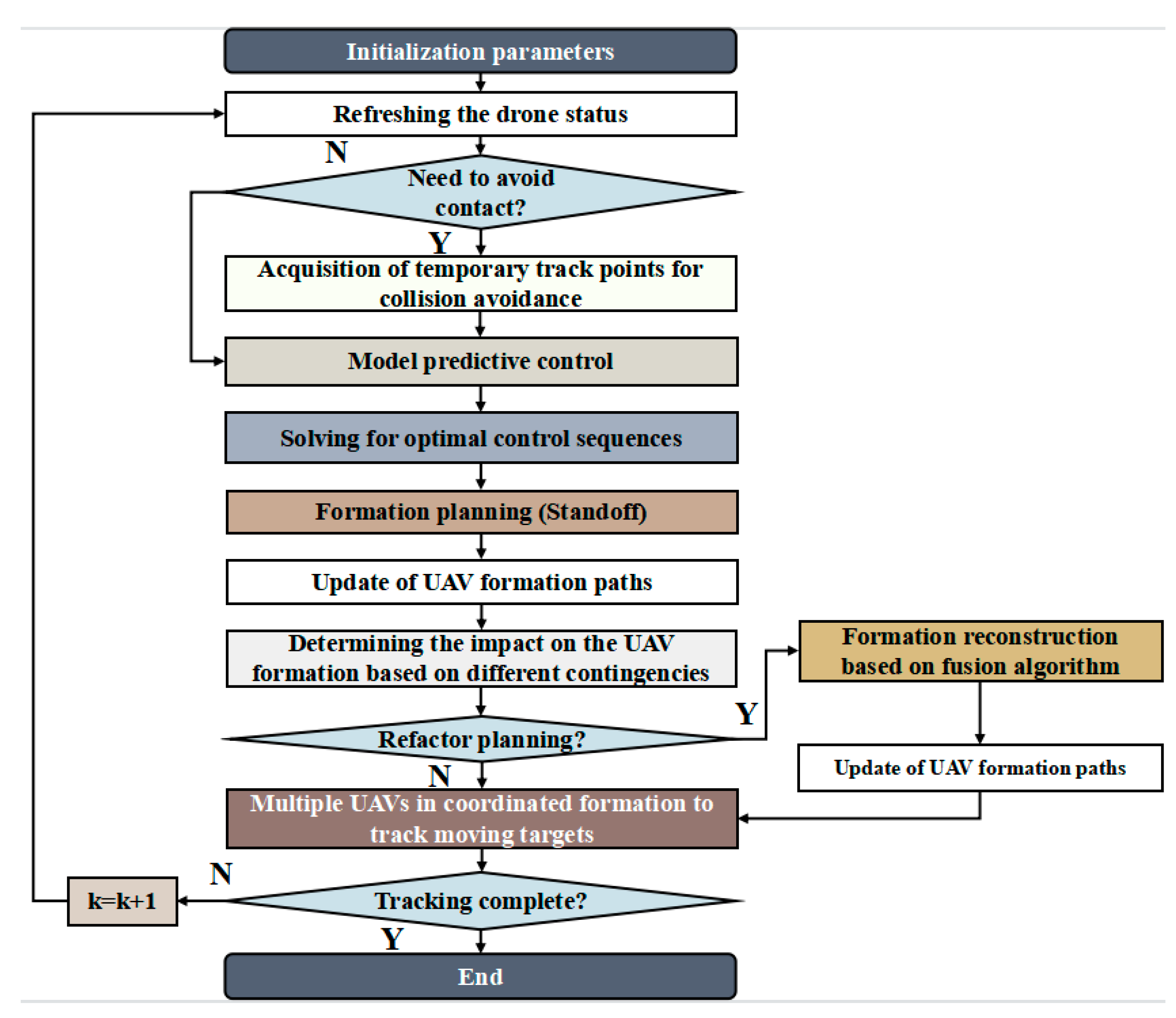
3.3. Application Steps of Multi-UAV Cooperative Tracking of the Moving Target Based on the Fusion Algorithm

The following steps are taken to plan the coordinated tracking of the moving target by multiple UAVs.
Step 1: Consider the UAV’s own constraints, collision avoidance constraints and other conditions, and determine the number of participating tracking UAVs and UAV formation according to the type of the moving target and tracking needs.
Step 2: The Standoff algorithm and the model predictive control algorithm are fused to complement each other and form a fusion algorithm with more optimized performance. The specific fusion algorithm is as follows: given the basic information of prediction time domain, sampling period, UAV control input u i ( k 1 k ) and UAV state quantity [ x i ( k k ) , y i ( k k ) , z i ( k k ) ] at the current k moments, build the planning model that UAVs follow when tracking the moving target, carry out UAV finite time domain prediction trajectory based on collision avoidance constraint, at the same time use the Standoff algorithm to calculate UAV formation phase distribution value, and then build the multi-UAV formation model to reach cooperative tracking of the moving target.
Step 3: In the process of multi-UAV formation movement, determine in real time whether the UAV formation encounters an unexpected situation. If yes, go to step 4; if no, continue to track the moving target.
Step 4: When the UAV formation encounters an unexpected situation during the tracking process, UAVs need to use the fusion algorithm to carry out real-time trajectory planning, and the ‘feedback-correction’ mechanism to correct the trajectory until they resume the formation after the unexpected situation is resolved to continue tracking the moving target.

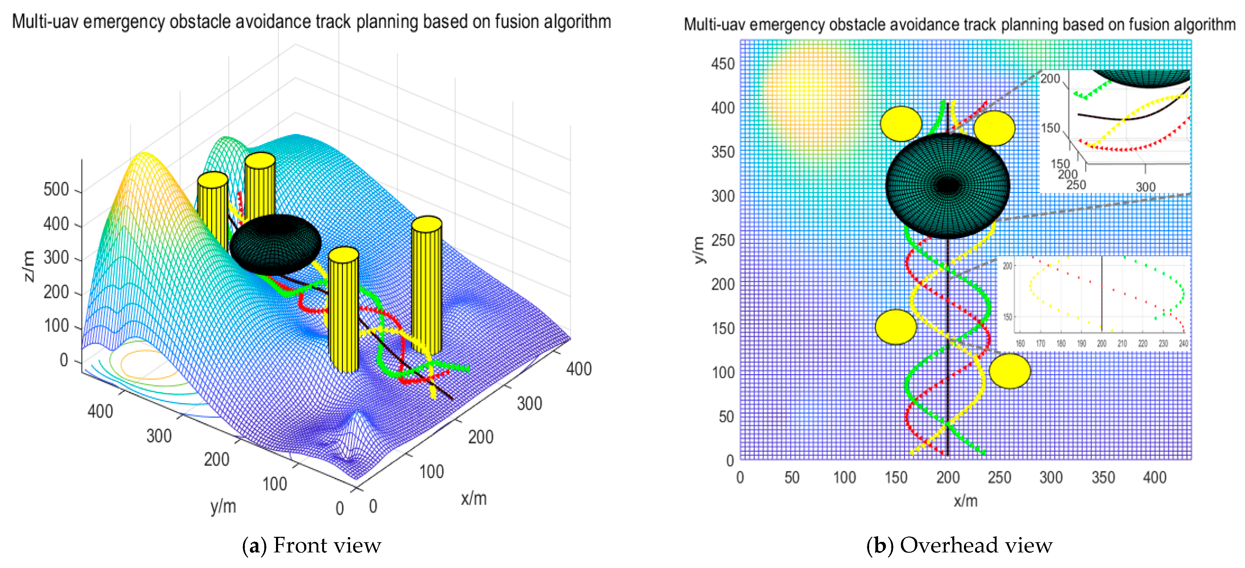
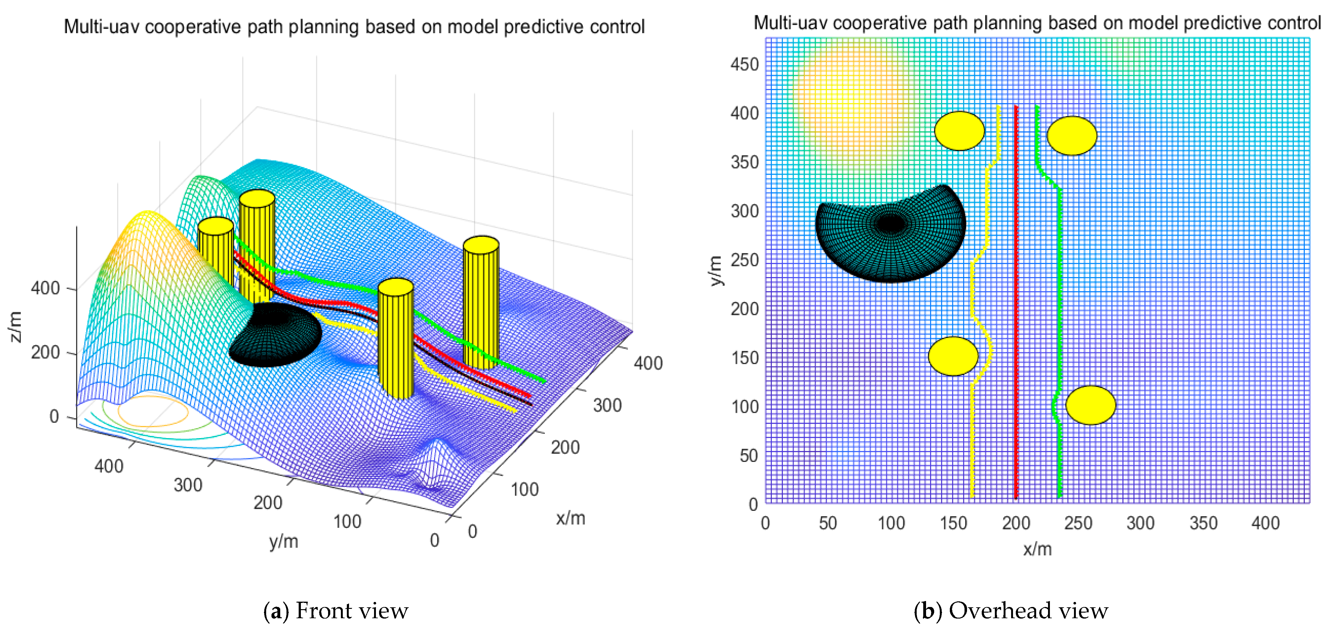
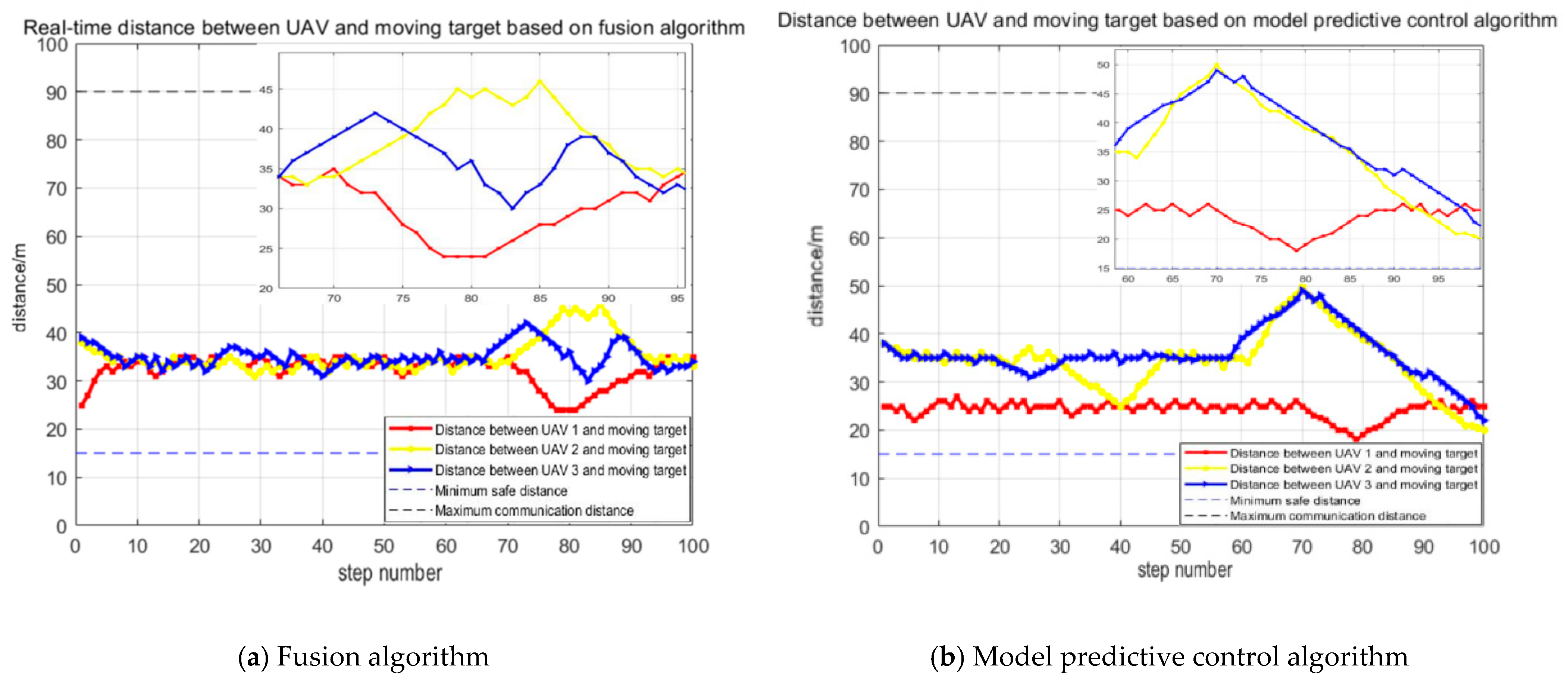
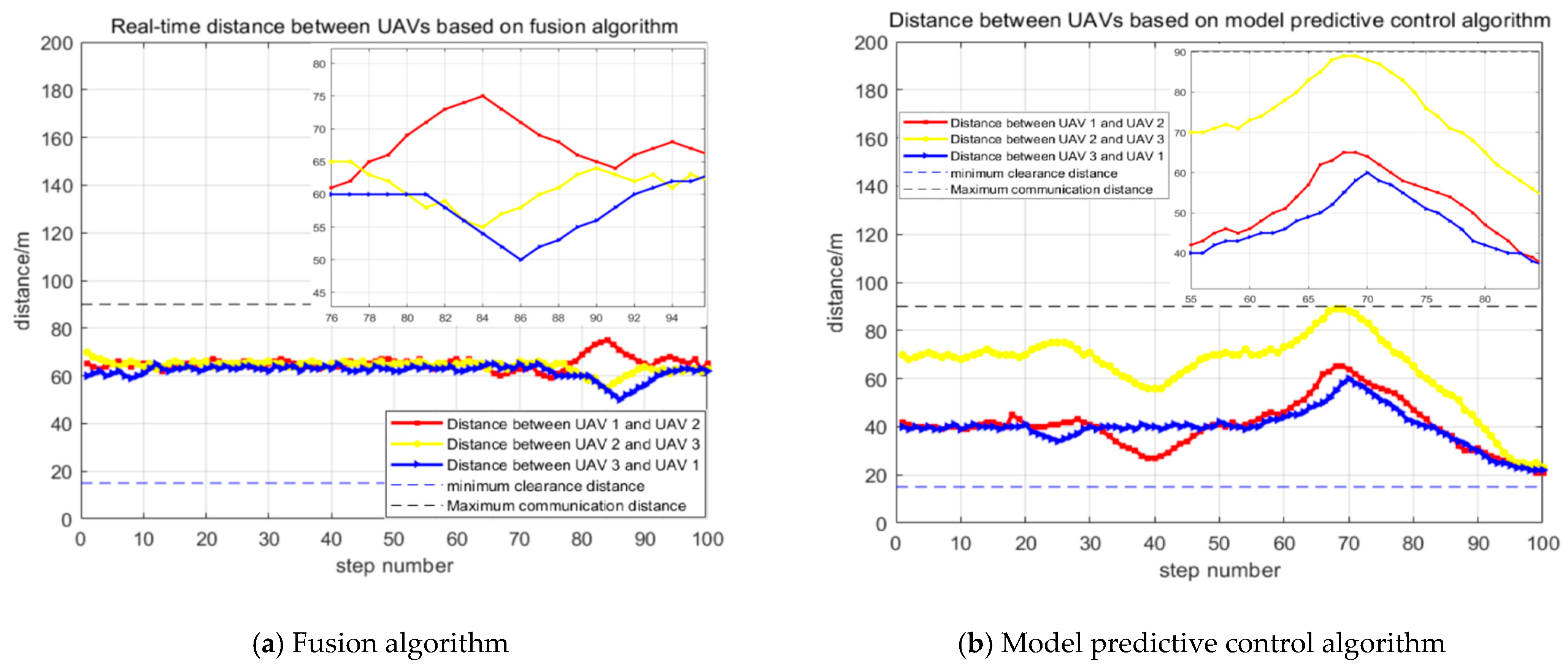
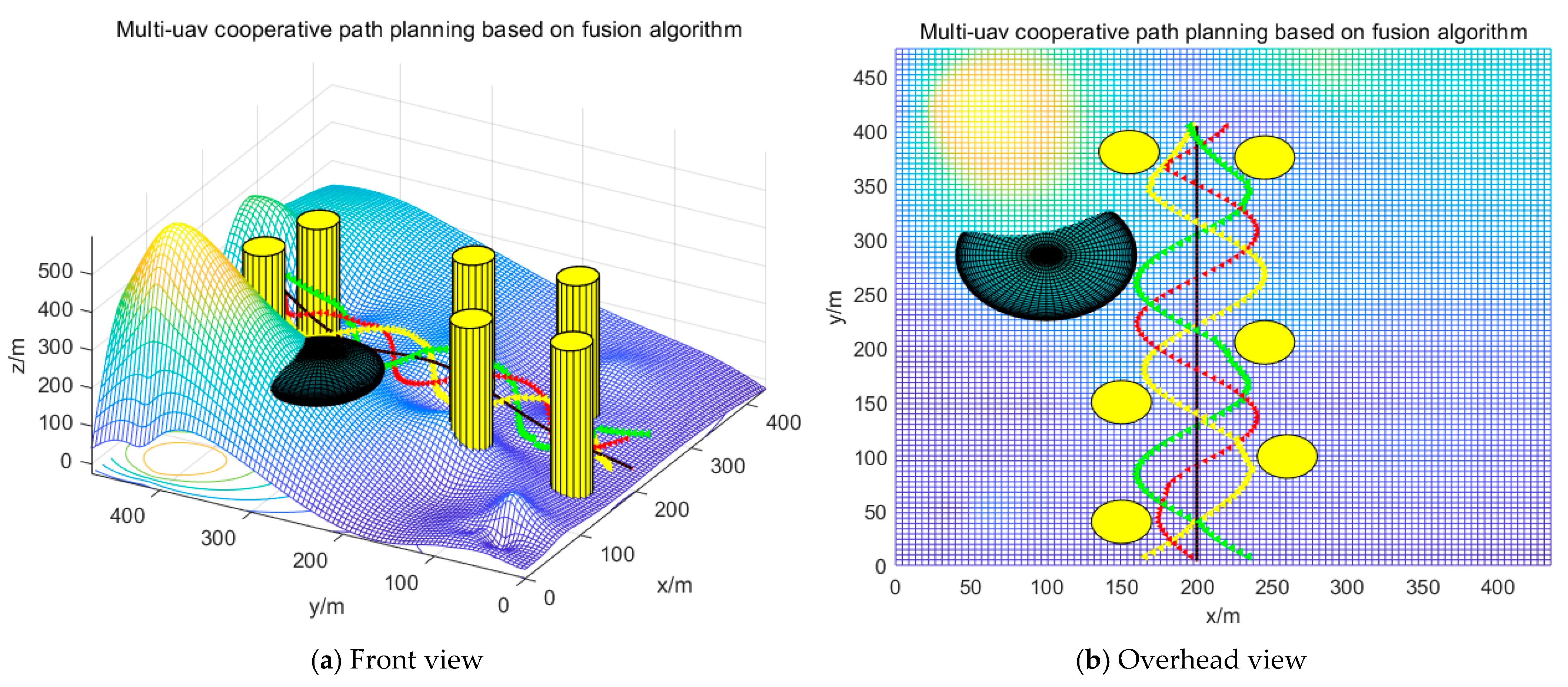
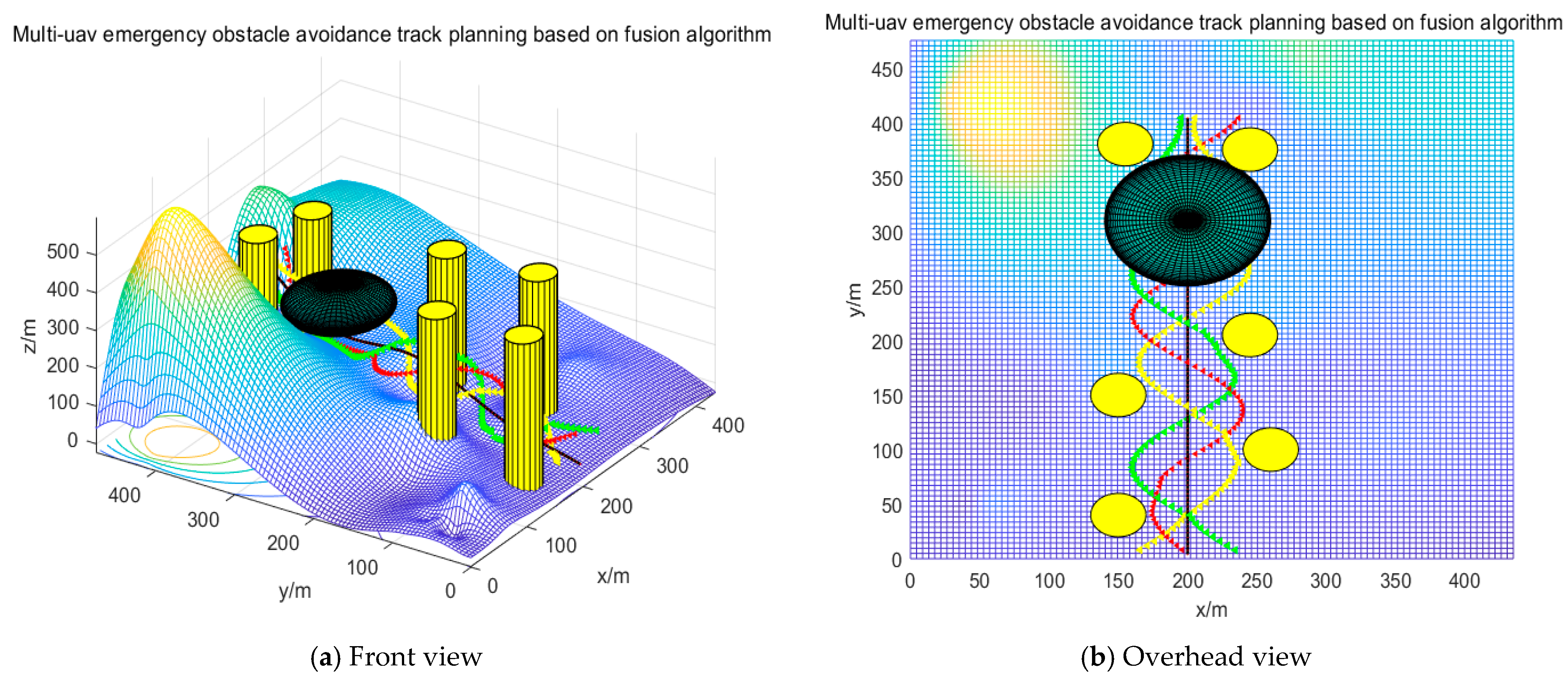
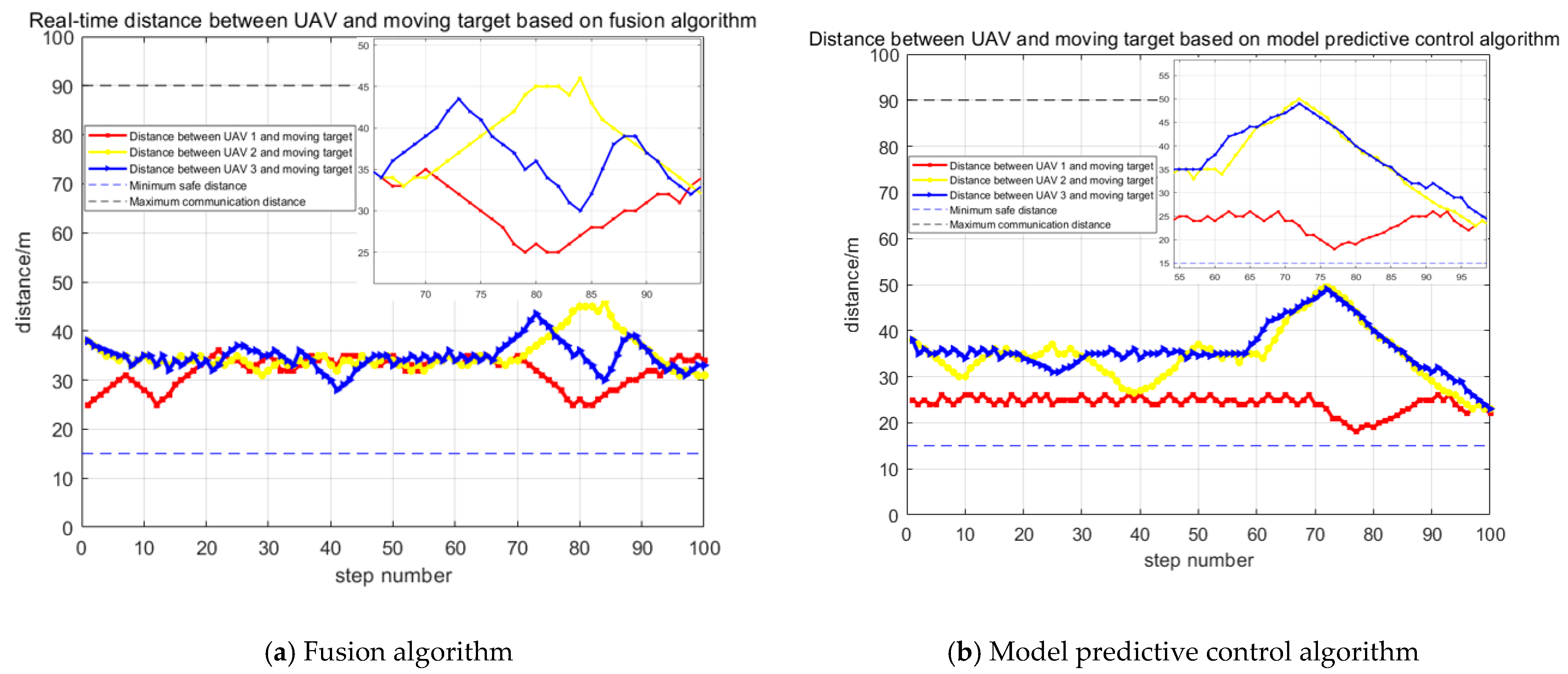
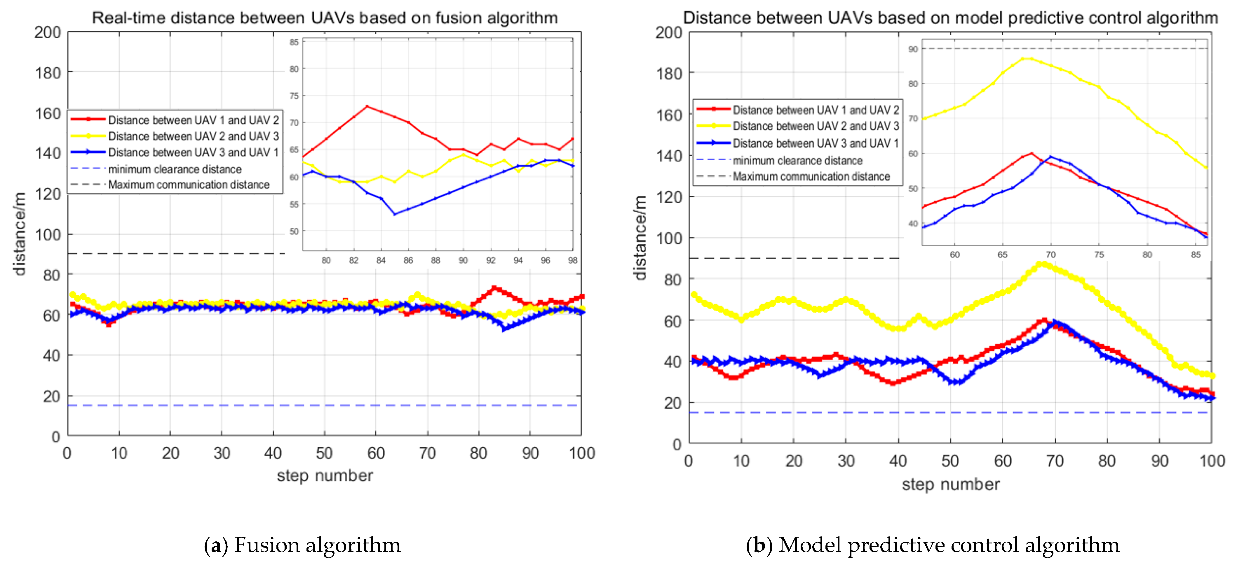
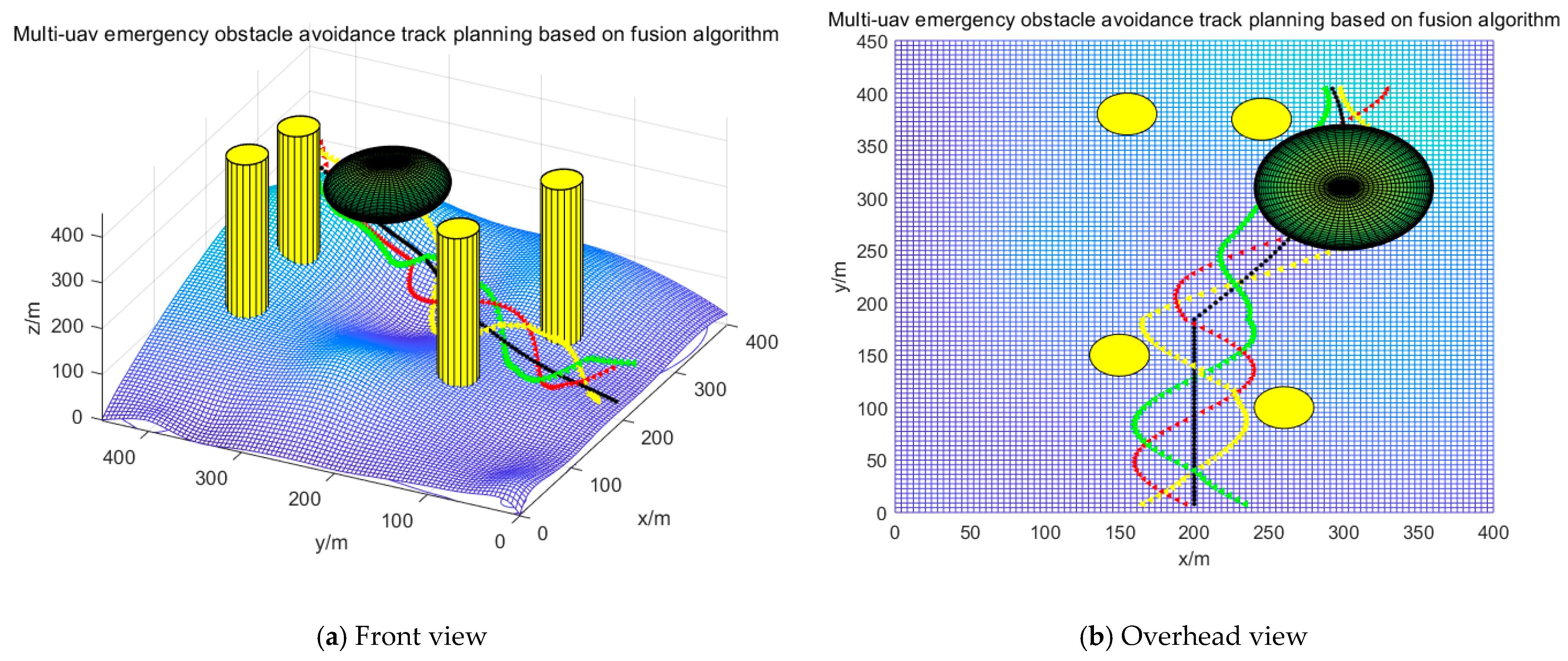
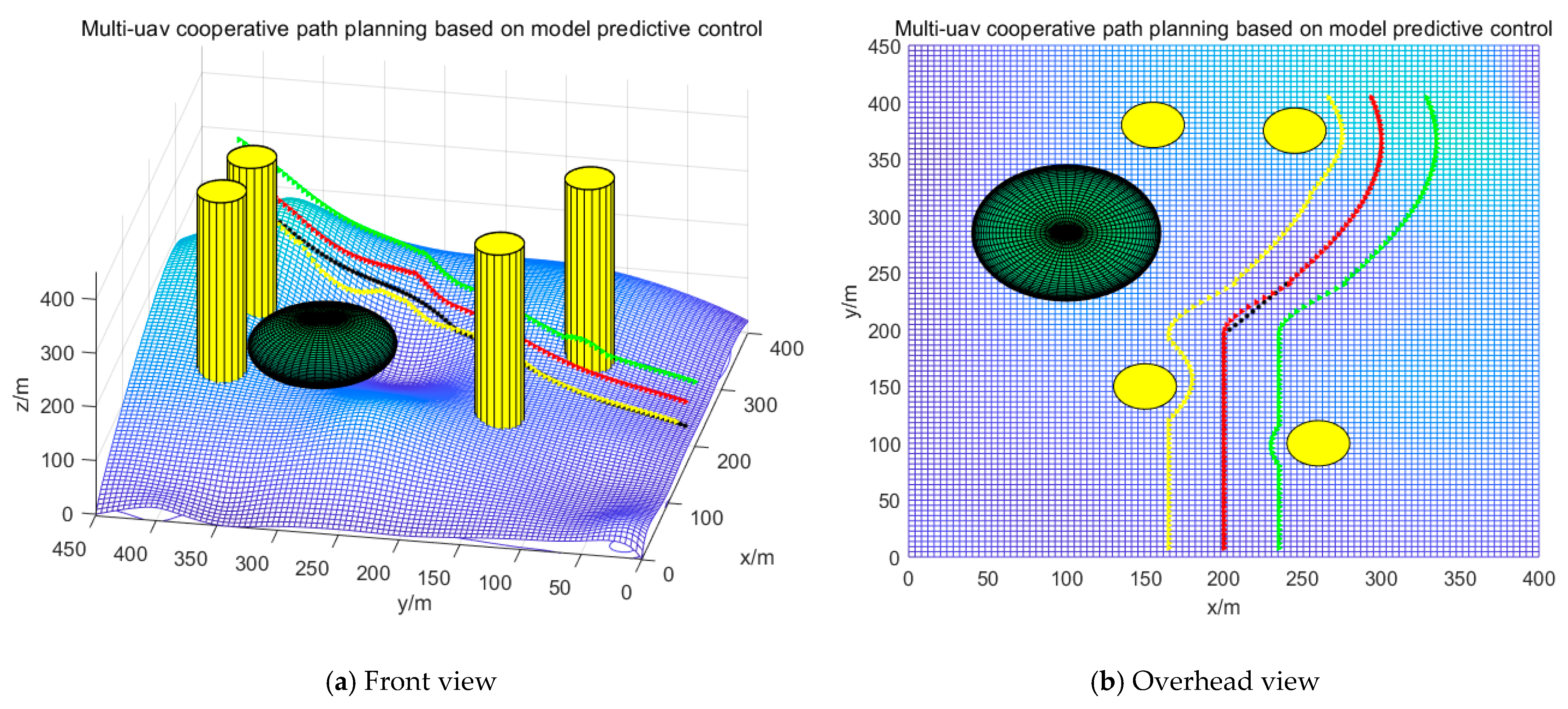
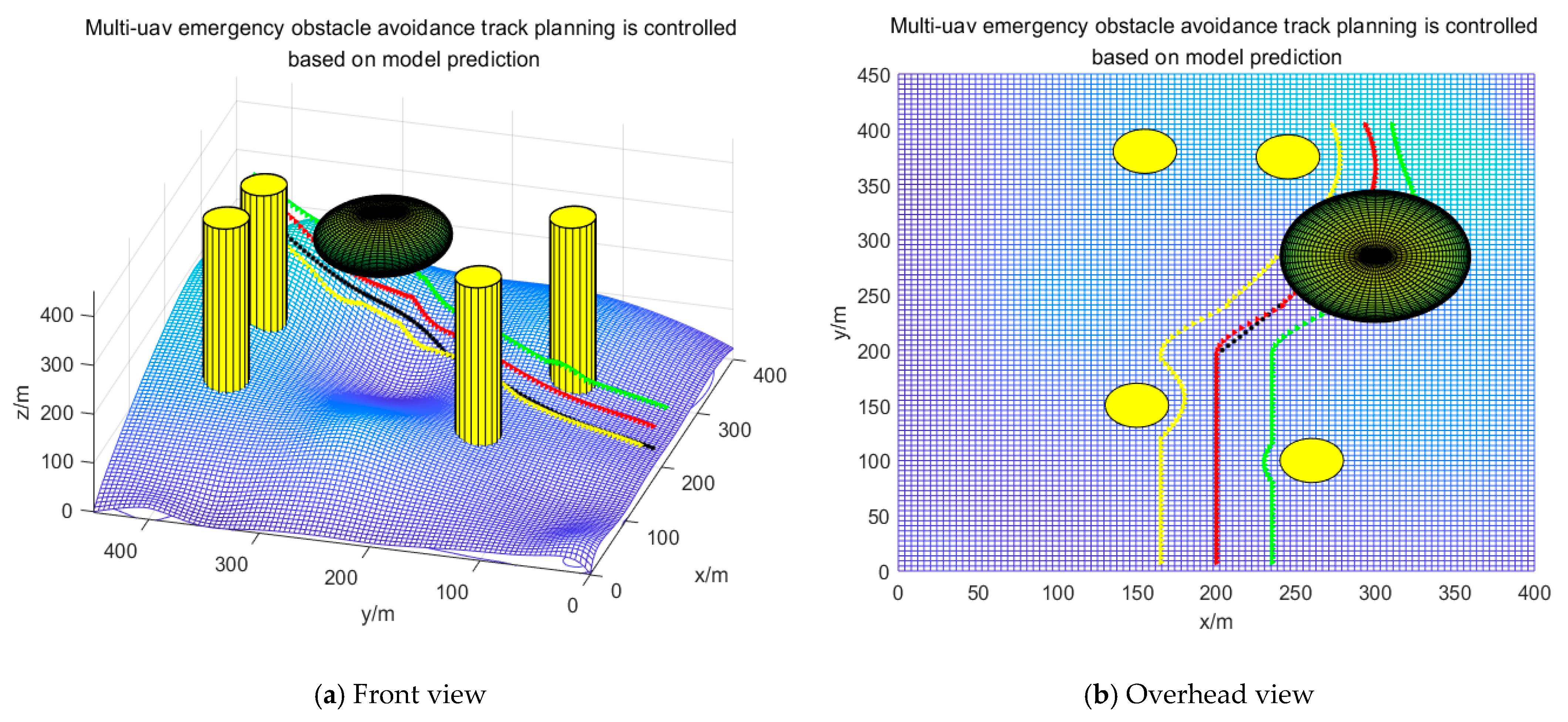
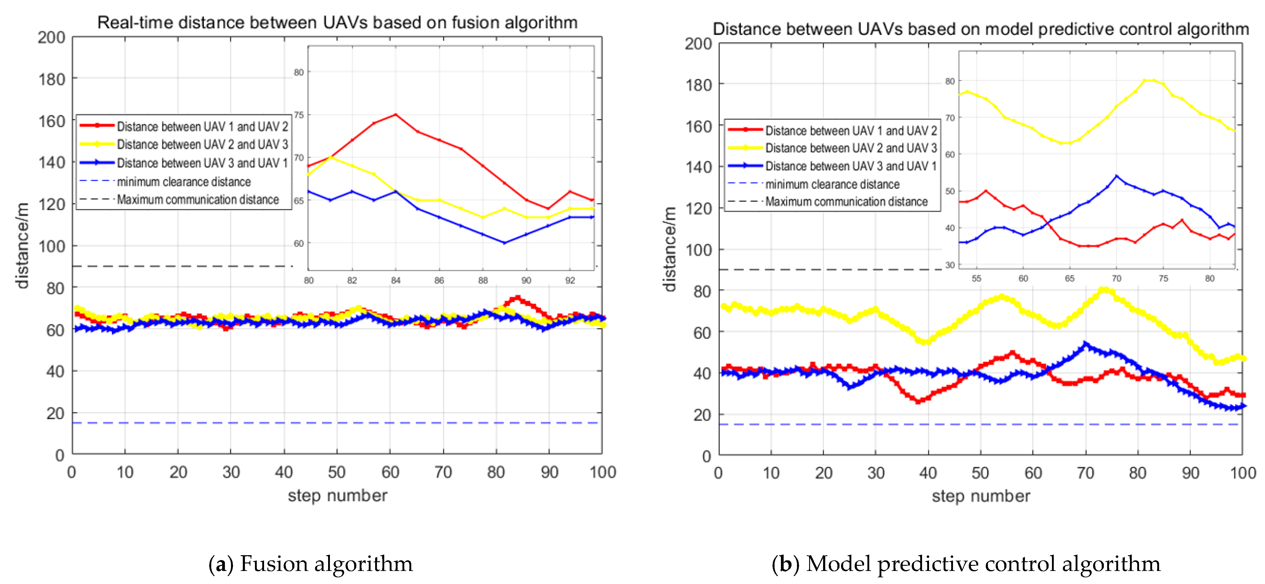
4. Simulation Verification

With parameters of UAVs and the moving target initialized according to the known information, simulation results have verified that UAVs are able to make trajectory planning through coordinated formation to track the moving target, under the premise that each UAV’s own constraints as well as constraints related to collision avoidance and obstacle avoidance are all considered. Under this verification, an ideal distance and angle between the UAV formation and the moving target is maintained, which makes the UAVs’ monitoring possible and effective. Simulation verification on reconfiguration of multi-UAV formation and trajectory replanning is also carried out, in which different contingencies are handled at the minimized formation planning cost so that UAV trajectory planning can be less dependent on priori information. Initialization information is shown in Table 1.
In this paper, the simulation environment is based on MATLAB R2020b software. The map modelling is based on the undulating terrain of the mountainous landscape, the terrain obstacle composition is mainly derived from the original terrain and the threat of mountain peaks, and the mathematical model of the terrain is artificially formulated. To further approximate the real flight scenario, a safety buffer zone is set up around the UAV and the obstacles are divided into static obstacle modelling and emergent obstacles, with the static obstacle model being approximated by a cylinder and the emergent obstacle model by a sphere. In addition, to further enhance the accuracy of the simulation, the rasterised map environment, i.e., taking into account terrain obstacles, no-fly zones, threat zones, etc., rasterises the map, with each grid called a cell, converts the 3D mathematical model of the map into vector structure data and then into a raster structure, giving each raster cell unique attributes to represent entities. In this paper, the rasterized map unit length is determined to be 5 m with an accuracy of 0.1 m, and its 3D height information is formulated by human.
In this paper, the moving target is set as a low altitude slow speed target, the UAV collision avoidance safety distance is defined as 15 m, the maximum communication radius between UAVs is 90 m, and the UAV detection coverage range is 40 m. For specific sudden obstacle model information, see Table 2. The simulation system randomly selects the established sudden obstacle model for testing the fusion algorithm applied to UAV trajectory planning and its formation reconfiguration capability. When the simulation system selects the sudden obstacle 1, UAVs in formation follow the way as planned by conventional trajectory in their flight, taking into account constraints such as collision avoidance and obstacle avoidance, and maximizing multi-UAV sensors’ monitoring coverage. For simulation details, see Figure 6. When the simulation system selects the sudden obstacle 2, it needs to use the fusion algorithm to quickly develop a reconfiguration plan for UAV cooperative formation. Simulation results are shown in Figure 7. To verify the effectiveness of the fusion algorithm, this paper uses the model predictive control algorithm to carry out comparative simulations of same-state trajectory planning, as shown in Figure 8 and Figure 9.
The black trajectory in Figure 6, Figure 7, Figure 8 and Figure 9 is the trajectory of the moving target, and the red, yellow, and green trajectories respectively represent the trajectory planning results of UAV1, UAV2, and UAV3 tracking the moving target. According to the figures, it can be seen that the three UAVs can satisfy several conditions such as their own flight constraints, constraints related to collision avoidance and obstacle avoidance, and carry out real-time stable formation tracking of the moving target. As illustrated by Figure 6 and Figure 7, the simulation of the fusion algorithm makes it possible for UAVs to stably track the target that moves along the established trajectory. Four static obstacles, together with some sudden obstacles, are avoided, which justifies advantages and effectiveness of the fusion algorithm. Unlike the Standoff algorithm that proves to be poor in real-time obstacle avoidance, the fusion algorithm works well in this regard: the three UAVs are distributed around the moving target to maximize the detection coverage of UAV sensors. Thus, the formation reconfiguration task is effectively completed and the unexpected obstacle is successfully bypassed. Figure 8 and Figure 9 only use a single model predictive control algorithm to carry out track planning. Although the vehicles can continue tracking the moving target, their formation is unstable, and the detection coverage for the moving target is insufficient, as shown in Figure 10 and Figure 11.
A comparison of the simulated data in Figure 10 and Figure 11 verifies that the fusion algorithm is effective in avoiding unexpected obstacles when applied to the trajectory planning process UAVs take through cooperative formation when tracking the moving target. Compared with the model predictive control algorithm alone, the fusion algorithm shows its advantage in formation control with the help of the Standoff algorithm, allowing multiple UAVs to move in a circular motion around the target, maximizing UAV sensors’ monitoring range and enabling cooperative formation to track the target. As can be seen in Figure 10, the fusion-based algorithm results in a smaller distance between the UAV and the moving target in real time, and a tighter formation which can be maintained after emergency obstacle avoidance. In Figure 11, the fusion-based UAV spacing remains more stable and less volatile regarding the distance each UAV keeps from the other.
In order to further verify the effectiveness of the fusion algorithm applied to UAVs’ tracking of a moving target, and to verify the real-time obstacle avoidance capability of the fusion algorithm, the number of static obstacles is increased to six in this paper, and the specific system simulation results are shown in Figure 12 and Figure 13. At the same time, the same state comparison simulation experiments are carried out using the model predictive control algorithm, as shown in Figure 14 and Figure 15.
As can be seen from the figure above, by increasing the number of static obstacles to six in the scenario, the three UAVs can still satisfy multiple conditions such as their own flight constraints and obstacle avoidance constraints, and be distributed around the moving target in a class circle to maximize the UAV sensor’s detection coverage, and effectively complete the task of formation reconstruction and real-time stable formation tracking of the moving target on the basis of collaborative formation trajectory planning in complex environments. A comparison between Figure 13 and Figure 15 shows that the single model predictive control algorithm for track planning, although also capable of continuously tracking moving targets, has an unstable formation and thus insufficient detection coverage for moving targets. Specific tracking accuracy parameters are shown in Figure 16 and Figure 17.
In order to test the effectiveness of the fusion optimization algorithm applied to UAV cooperative formation tracking moving target trajectory planning for different trajectory targets, this paper changes the established motion trajectory of the moving target, increases the degrees of freedom of the moving target, expands the 2-dimensional motion of the moving target to 3-dimensional motion, and at the same time adjusts the complex 3-dimensional environment model and changes the dynamic obstacle position, the specific simulation results are shown in Figure 18 and Figure 19. Using the model predictive control algorithm to carry out the same state comparison simulation experiments, as shown in Figure 20 and Figure 21.
According to the figure above, in the context of changing the complex map environment and changing the trajectory of the moving target, the UAVs can still satisfy multiple conditions such as their own flight constraints, collision avoidance and obstacle avoidance constraints, etc., and distribute around the moving target in a class circle to maximize the detection coverage of the UAV sensors, and effectively complete the task of formation reconstruction based on the realization of trajectory planning of multi-UAVs in cooperative formation in a complex environment, and carry out real-time stable formation tracking of the moving target. This demonstrates the effectiveness of the fusion algorithm for tracking moving targets in a complex and variable environment. Specific tracking accuracy parameters are shown in Figure 22 and Figure 23.
As can be seen in Figure 22, the fusion-based algorithm has a smaller distance between the UAV and the moving target in real time and maintains a tighter formation, which can be maintained even after emergency obstacle avoidance. In Figure 23, the fusion-based UAV spacing remains stable and less volatile when comparing distances between UAVs.

5. Discussion

In order to evaluate the proposed fusion algorithm, this paper makes a judgment about the sensors’ detection coverage during multi-UAV tracking of a moving target in coordinated formation, while maximizing their detection range and minimizing the probability of target loss in UAV formation, and compares it with the use of a single model predictive control algorithm to verify that the fusion algorithm helps to improve UAV target monitoring capabilities.
For the target tracking effect and monitoring capability, this paper compares the fusion algorithm and the single model predictive control algorithm in the same environment, guiding multiple UAVs to cooperate in formation as they track the moving target, counting the frequency of UAV sensors to effectively monitor the moving target. Experimental results are shown in Table 3, according to which, the three UAVs effectively monitored target coverage using the fusion algorithm a total of 286 times in Scene 1, compared with 268 effective monitoring times using the single model predictive control algorithm, resulting in a 6.72% increase in combined monitoring coverage; in Scene 2 the three UAVs effectively monitored target coverage a total of 283 times with the help of the fusion algorithm, compared with 264 effective monitoring times using the single model predictive control algorithm, resulting in a 7.20% increase in combined monitoring coverage; and in Scene 3 three UAVs effectively monitored target coverage a total of 287 times with the fusion algorithm, while the effective number of monitoring using a single model predictive control algorithm was 269, with a 6.69% increase in comprehensive monitoring coverage, which in turn can be derived from the advantages of the fusion algorithm in terms of tracking and monitoring effectiveness. The improvement of monitoring ability comes from the effective integration of the model predictive control algorithm and the Standoff algorithm in Section 3.2.1 and Section 3.2.2. The former uses a ‘feedback-correction’ mechanism to correct UAV trajectories, ensuring real-time tracking of moving target trajectory planning, while enabling reconfiguration and planning of multiple UAVs in formation reaching the least-cost goal. The latter ensures cooperative formation control of multiple UAVs, builds UAV sensor monitoring models, maximizes sensors’ monitoring range and reduces the probability of UAVs losing the moving target. Clearly, the fusion algorithm displays a better tracking effect and monitoring capability in the test.
The fusion algorithm promotes the construction of a multi-UAV track planning model, which obtains a more adaptive tracking strategy and effectively solves the problem of multi-UAV formation reconfiguration and obstacle avoidance in emergency situations. From the experimental results, it can be seen that the algorithm has great advantages in terms of tracking effectiveness and monitoring capability, and can support UAV target tracking in uncertain environments. Although some work has been done in this paper on UAV tracking effectiveness and monitoring capability, there are still some challenges in deploying the algorithm to real UAVs. In practice, external interference, noise and air resistance have a dynamic effect on UAV trajectory planning, making it difficult to keep the UAV maneuvering at all times, and time delays in communication between multiple UAVs may occur. No matter how good the UAV’s trajectory planning is in the simulation environment, it is still far from real application. However, we can keep increasing the realism of the scenarios and models in the simulation environment, and thus get closer to the real environment. For future research, we will consider implementing more detailed UAV control, including controlling the UAV with motor speed, acquiring target information through the UAV’s vision sensors and acquiring range information through LIDAR as status information, thus achieving target tracking in a more realistic 3D scene.

6. Conclusions

In this paper, a fusion and optimization method is proposed for trajectory planning UAVs make through cooperative formation when tracking the moving target, a framework for the multi-UAV tracking system is designed, and research on stable tracking is carried out to maximize UAV sensors’ coverage as they monitor the moving target, which in turn reduces the probability of target loss in the tracking process. Against a complex three-dimensional environment in which priori information is insufficient, the fusion algorithm promotes the reconfiguration and planning of multi-UAV formation at the minimum cost, and thus ensures the existence and maintenance of the multi-UAV formation. The simulation verifies the effectiveness of the fusion algorithm applied to multi-UAV cooperative formation, keeping off deficiency in avoiding real-time obstacles facing the Standoff algorithm.
Some future work includes implementing more detailed UAV control for 3D spatial and target tracking in more complex environments, setting up more realistic scenarios (different flight scenarios with different numbers of tracked targets) for extensive simulation validation, and adding on-board sensors to obtain more data as status information, allowing multiple UAVs to carry out collaborative tracking of a moving target closer to realistic scenarios, so that fusion optimization algorithms can find their market in actual UAV trajectory planning in the future.

Author Contributions

Resources, B.L. and R.M.; methodology, C.S.; validation, C.S., S.B. and J.H.; writing—original draft preparation, B.L. and C.S.; writing—review and editing, K.W. and E.N.; funding acquisition, K.W. and B.L. All authors have read and agreed to the published version of the manuscript.

Funding

This research was partially funded by Project supported by the National Nature Science Foundation of China under grant no. 62003267, the Fundamental Research Funds for the Central Universities under grant no. G2022KY0602, the Technology on Electromagnetic Space Operations and Applications Laboratory under grant no. 2022ZX0090, the Key Research and Development Program of Shaanxi Province under grant no. 2023-GHZD-33, and the key core technology research plan of Xi’an under grant no. 21RGZN0016.

Data Availability Statement

Data sharing not applicable.

Conflicts of Interest

The authors declare no conflict of interest.

References

  1. Huang, G.; Hu, M.; Yang, X.; Lin, P. Multi-UAV Cooperative Trajectory Planning Based on FDS-ADEA in Complex Environments. Drones 2023, 7, 55. [Google Scholar] [CrossRef]
  2. Li, B.; Gan, Z.; Chen, D.; Aleksandrovich, S. UAV Maneuvering Target Tracking in Uncertain Environments Based on Deep Reinforcement Learning and Meta-Learning. Remote Sens. 2020, 12, 3789. [Google Scholar] [CrossRef]
  3. Zhang, J.; Yan, J.; Zhang, P.; Kong, X. Design and Information Architectures for an Unmanned Aerial Vehicle Cooperative Formation Tracking Controller. IEEE Access 2018, 6, 45821–45833. [Google Scholar] [CrossRef]
  4. Li, B.; Yang, Z.P.; Chen, D.Q.; Liang, S.Y.; Ma, H. Maneuvering target tracking of UAV based on MN-DDPG and transfer learning. Def. Technol. 2021, 17, 10. [Google Scholar] [CrossRef]
  5. Bian, L.; Sun, W.; Sun, T. Trajectory Following and Improved Differential Evolution Solution for Rapid Forming of UAV Formation. IEEE Access 2019, 7, 169599–169613. [Google Scholar] [CrossRef]
  6. Liu, W.; Zheng, X.; Luo, Y. Cooperative search planning in wide area via multi-UAV formations based on distance probability. In Proceedings of the 2020 3rd International Conference on Unmanned Systems (ICUS), Harbin, China, 27–28 November 2020; pp. 1072–1077. [Google Scholar] [CrossRef]
  7. Li, Y.; Tian, B.; Yang, Y.; Li, C. Path planning of robot based on artificial potential field method. In Proceedings of the 2022 IEEE 6th Information Technology and Mechatronics Engineering Conference (ITOEC), Chongqing, China, 4–6 March 2022; pp. 91–94. [Google Scholar] [CrossRef]
  8. Liang, Q.; Zhou, H.; Xiong, W.; Zhou, L. Improved artificial potential field method for UAV path planning. In Proceedings of the 2022 14th International Conference on Measuring Technology and Mechatronics Automation (ICMTMA), Changsha, China, 15–16 January 2022; pp. 657–660. [Google Scholar] [CrossRef]
  9. Zong, C.; Yao, X.; Fu, X. Path Planning of Mobile Robot based on Improved Ant Colony Algorithm. In Proceedings of the 2022 IEEE 10th Joint International Information Technology and Artificial Intelligence Conference (ITAIC), Chongqing China, 17–19 June 2022; pp. 1106–1110. [Google Scholar] [CrossRef]
  10. Gao, Y. An Improved Hybrid Group Intelligent Algorithm Based on Artificial Bee Colony and Particle Swarm Optimization. In Proceedings of the 2018 International Conference on Virtual Reality and Intelligent Systems (ICVRIS), Hunan, China, 10–11 August 2018; pp. 160–163. [Google Scholar] [CrossRef]
  11. Ma, F.; Lu, J.; Liu, L.; He, Y. Application of Improved Single Neuron Adaptive PID Control Method in the Angle Predefined Loop of Active Radar Seeker for Anti-radiation Missile. In Proceedings of the 2021 IEEE 4th Advanced Information Management, Communicates, Electronic and Automation Control Conference (IMCEC), Chongqing, China, 18–20 June 2021; pp. 2160–2164. [Google Scholar] [CrossRef]
  12. Xingke, L.; Xuesong, C.; Shuting, C. Smoothing Method for Nonlinear Optimal Control Problems with Inequality Path Constraints. In Proceedings of the 2019 Chinese Control and Decision Conference (CCDC), Nanchang, China, 3–5 June 2019; pp. 5350–5353. [Google Scholar] [CrossRef]
  13. Anastasiou, D.; Nanos, K.; Papadopoulos, E. Robust Model-based H∞ control for Free-floating Space Manipulator Cartesian Motions. In Proceedings of the 2022 30th Mediterranean Conference on Control and Automation (MED), Vouliagmeni, Greece, 28 June–1 July 2022; pp. 598–603. [Google Scholar] [CrossRef]
  14. Yu, L.; He, G.; Wang, X.; Zhao, S. Robust Fixed-Time Sliding Mode Attitude Control of Tilt Trirotor UAV in Helicopter Mode. IEEE Trans. Ind. Electron. 2022, 69, 10322–10332. [Google Scholar] [CrossRef]
  15. Vazquez, S.; Rodriguez, J.; Rivera, M.; Franquelo, L.G.; Norambuena, M. Model Predictive Control for Power Converters and Drives: Advances and Trends. IEEE Trans. Ind. Electron. 2017, 64, 935–947. [Google Scholar] [CrossRef] [Green Version]
  16. Rodriguez, J.; Kazmierkowski, M.P.; Espinoza, J.R.; Zanchetta, P.; Abu-Rub, H.; Young, H.A.; Rojas, C.A. State of the Art of Finite Control Set Model Predictive Control in Power Electronics. IEEE Trans. Ind. Inform. 2013, 9, 1003–1016. [Google Scholar] [CrossRef]
  17. Sahu, A.; Kandath, H.; Krishna, K.M. Model predictive control based algorithm for multi-target tracking using a swarm of fixed wing UAVs. In Proceedings of the 2021 IEEE 17th International Conference on Automation Science and Engineering (CASE), Lyon, France, 23–27 August 2021; pp. 1255–1260. [Google Scholar]
  18. Ille, M.; Namerikawa, T. Collision avoidance between multi-UAV systems considering formation control using MPC. In Proceedings of the 2017 IEEE International Conference on Advanced Intelligent Mechatronics (AIM), Munich, Germany, 3–7 July 2017; pp. 651–656. [Google Scholar] [CrossRef]
  19. Muslimov, T.Z.; Munasypov, R.A. Coordinated UAV Standoff Tracking of Moving Target Based on Lyapunov Vector Fields. In Proceedings of the 2020 International Conference Nonlinearity, Information and Robotics (NIR), Innopolis, Russia, 3–6 December 2020; pp. 1–5. [Google Scholar] [CrossRef]
  20. Guo, Q.; Peng, J.; Xu, W.; Liang, W.; Jia, X.; Xu, Z.; Yang, Y.; Wang, M. Minimizing the Longest Tour Time Among a Fleet of UAVs for Disaster Area Surveillance. IEEE Trans. Mob. Comput. 2022, 21, 2451–2465. [Google Scholar] [CrossRef]
  21. Niu, Y.; Liu, J.; Xiong, J.; Li, J.; Shen, L. Research on cooperative ground multi-target guidance method for UAV swarm tracking. China Sci. Technol. Sci. 2020, 50, 403–422. [Google Scholar]
  22. Zhang, Y.; Fang, G.-W.; Yang, X.-X. Cooperative tracking of multiple UAVs under command decision. Flight Mech. 2020, 38, 28–33. [Google Scholar] [CrossRef]
  23. Zhu, Q.; Zhou, R.; Dong, Z.-N.; Li, H. Two-machine cooperative standoff target tracking under angular measurement. J. Beijing Univ. Aeronaut. Astronaut. 2015, 41, 2116–2123. [Google Scholar] [CrossRef]
  24. Wang, D.; Wu, M.; He, Y.; Pang, L.; Xu, Q.; Zhang, R. An HAP and UAVs Collaboration Framework for Uplink Secure Rate Maximization in NOMA-Enabled IoT Networks. Remote Sens. 2022, 14, 4501. [Google Scholar] [CrossRef]
  25. Wang, D.; He, T.; Zhou, F.; Cheng, J.; Zhang, R.; Wu, Q. Outage-driven link selection for secure buffer-aided networks. Sci. China Inf. Sci. 2022, 65, 182303. [Google Scholar] [CrossRef]
  26. Parisio, A.; Rikos, E.; Glielmo, L. A Model Predictive Control Approach to Microgrid Operation Optimization. IEEE Trans. Control. Syst. Technol. 2014, 22, 1813–1827. [Google Scholar] [CrossRef]
  27. Dantec, E.; Taix, M.; Mansard, N. First Order Approximation of Model Predictive Control Solutions for High Frequency Feedback. IEEE Robot. Autom. Lett. 2022, 7, 4448–4455. [Google Scholar] [CrossRef]
  28. Harinarayana, T.; Hota, S. Coordinated Standoff Target Tracking by Multiple UAVs in Obstacle-filled Environments. In Proceedings of the 2021 Seventh Indian Control Conference (ICC), Mumbai, India, 20–22 December 2021; pp. 111–116. [Google Scholar] [CrossRef]
  29. Song, R.; Long, T.; Wang, Z.; Cao, Y.; Xu, G. Multi-UAV Cooperative Target Tracking Method using sparse A search and Standoff tracking algorithms. In Proceedings of the 2018 IEEE CSAA Guidance, Navigation and Control Conference (CGNCC), Xiamen, China, 10–12 August 2018; pp. 1–6. [Google Scholar] [CrossRef]
  30. Abedini, A.; Bataleblu, A.A.; Roshanian, J. Robust Backstepping Control of Position and Attitude for a Bi-copter Drone. In Proceedings of the 2021 9th RSI International Conference on Robotics and Mechatronics (ICRoM), Tehran, Iran, 17–19 November 2021; pp. 425–432. [Google Scholar] [CrossRef]
  31. Cheng, Z.; Zhao, L.; Shi, Z. Decentralized Multi-UAV Path Planning Based on Two-Layer Coordinative Framework for Formation Rendezvous. IEEE Access 2022, 10, 45695–45708. [Google Scholar] [CrossRef]
  32. Wang, D.; Zhou, F.; Lin, W.; Ding, Z.; Al-Dhahir, N. Cooperative Hybrid Non-Orthogonal Multiple Access Based Mobile-Edge Computing in Cognitive Radio Networks. IEEE Trans. Cogn. Commun. Netw. 2022, 8, 1104–1117. [Google Scholar] [CrossRef]
  33. Shaowu, D.; Chaolun, Z.; Fei, L.; Xu, H.; Guorong, Z. A model predictive control algorithm for UAV formations under multiple constraints. Control. Decis. Mak. 2023, 38, 706–714. [Google Scholar] [CrossRef]
  34. Fuchun, L.; Huanli, G. Research on model predictive control algorithms for small unmanned helicopters. Control. Theory Appl. 2018, 35, 1538–1545. [Google Scholar]
  35. Haiou, L.; Yuxuan, H.; Qingxiao, L.; Shihao, L.; Huiyan, C.; Li, C. Research on the search strategy of different detection distance sensors. J. Beijing Univ. Technol. 2023, 43, 151–160. [Google Scholar] [CrossRef]
  36. Fan, G.; Zhao, Y.; Guo, Z.; Jin, H.; Gan, X.; Wang, X. Towards Fine-Grained Spatio-Temporal Coverage for Vehicular Urban Sensing Systems. In Proceedings of the IEEE INFOCOM 2021—IEEE Conference on Computer Communications, Vancouver, BC, Canada, 10–13 May 2021; pp. 1–10. [Google Scholar] [CrossRef]
  37. Wang, H.; Liu, C.H.; Dai, Z.; Tang, J.; Wang, G. Energy-Efficient 3D Vehicular Crowdsourcing for Disaster Response by Distributed Deep Reinforcement Learning. In Proceedings of the 27th ACM SIGKDD Conference on Knowledge Discovery & Data Mining (KDD ‘21), Washington, DC, USA, 14–18 August 2021; Association for Computing Machinery: New York, NY, USA, 2021; pp. 3679–3687. [Google Scholar] [CrossRef]
  38. Cao, Y.; Cheng, X.; Mu, J. Concentrated Coverage Path Planning Algorithm of UAV Formation for Aerial Photography. IEEE Sens. J. 2022, 22, 11098–11111. [Google Scholar] [CrossRef]
Figure 1. Schematic diagram of modeling of 3D environment and obstacles.
Drones 07 00196 g001
Figure 2. Schematic diagram of observation coverage.
Drones 07 00196 g002
Figure 3. Framework diagram of how UAVs make track planning as they track the moving target through cooperative formation.
Drones 07 00196 g003
Figure 4. Framework diagram of multi-UAV trajectory planning based on the fusion algorithm.
Drones 07 00196 g004
Figure 5. Schematic of formation control using the Standoff algorithm.
Drones 07 00196 g005
Figure 6. Scene 1-simulation of multiple UAVs using the fusion algorithm for coordinated formation tracking.
Drones 07 00196 g006
Figure 7. Scene 1-simulation of multiple UAVs using the fusion algorithm for reconfiguration of cooperative formation.
Drones 07 00196 g007
Figure 8. Scene 1-simulation of multi-UAV coordinated formation tracking using the model predictive control algorithm.
Drones 07 00196 g008
Figure 9. Scene 1-simulation of multiple UAVs for reconfiguration of cooperative formation using the model predictive control algorithm.
Drones 07 00196 g009
Figure 10. Scene 1-simulation of real-time distance data with the moving target during formation reconstruction of multiple UAVs tracking the moving target.
Drones 07 00196 g010
Figure 11. Scene 1-simulation of real-time distance data between multiple UAVs during formation reconfiguration.
Drones 07 00196 g011
Figure 12. Scene 2-simulation of multiple UAVs using the fusion algorithm for coordinated formation tracking.
Drones 07 00196 g012
Figure 13. Scene 2-simulation of multiple UAVs using the fusion algorithm for reconfiguration of cooperative formation.
Drones 07 00196 g013
Figure 14. Scene 2-simulation of multi-UAV coordinated formation tracking using the model predictive control algorithm.
Drones 07 00196 g014
Figure 15. Scene 2-simulation of multiple UAVs for reconfiguration of cooperative formation using the model predictive control algorithm.
Drones 07 00196 g015
Figure 16. Scene 2-simulation of real-time distance data with the moving target during formation reconstruction of multiple UAVs tracking the moving target.
Drones 07 00196 g016
Figure 17. Scene 2-simulation of real-time distance data between multiple UAVs during formation reconfiguration.
Drones 07 00196 g017
Figure 18. Scene 3-simulation of multiple UAVs using the fusion algorithm for coordinated formation tracking.
Drones 07 00196 g018
Figure 19. Scene 3-simulation of multiple UAVs using the fusion algorithm for reconfiguration of cooperative formation.
Drones 07 00196 g019
Figure 20. Scene 3-simulation of multi-UAV coordinated formation tracking using the model predictive control algorithm.
Drones 07 00196 g020
Figure 21. Scene 3-simulation of multiple UAVs for reconfiguration of cooperative formation using the model predictive control algorithm.
Drones 07 00196 g021
Figure 22. Scene 3-simulation of real-time distance data with the moving target during formation reconstruction of multiple UAVs tracking the moving target.
Drones 07 00196 g022
Figure 23. Scene 3-simulation of real-time distance data between multiple UAVs during formation reconfiguration.
Drones 07 00196 g023
Table 1. Initialization of system parameters.
Serial NumberParameters NameParameter Value
1UAV1 starting position(200 m, 5 m, 115 m)
2UAV2 starting position(160 m, 5 m, 75 m)
3UAV3 starting position(240 m, 5 m, 75 m)
4Target starting position(200 m, 5 m, 95 m)
5UAV initial speed25 m/s
6UAV speed range[20 m/s, 40 m/s]
7Maximum yaw angle of UAVπ/4 rad
8Maximum pitch angle of UAVπ/4 rad
9Minimum turning radius for UAV10 m
10Number of UAVs N 3
11Maximum speed constraint for UAVs u i v m a x 40 m/s
12Minimum speed constraint for UAVs u i v m i n 10 m/s
13Maximum angular velocity constraint for UAVs u i w m a x 0.25 rad/s
Table 2. Sudden obstacle information.
Serial NumberCoordinate PositionRadius Size of Obstacle
1(100 m, 270 m, 250 m)50 m
2(200 m, 300 m, 250 m)50 m
Table 3. Count of effective detection UAV sensors.
UAV CategoryUsageEffective Number of Detected Steps
(Scene 1-Total: 100)
Effective Number of Detected Steps
(Scene 2-Total: 100)
Effective Number of Detected Steps
(Scene 3-Total: 100)
UAV1Fusion algorithm100100100
Model predictive control algorithm100100100
UAV2Fusion algorithm898892
Model predictive control algorithm868488
UAV3Fusion algorithm979595
Model predictive control algorithm828081
Disclaimer/Publisher’s Note: The statements, opinions and data contained in all publications are solely those of the individual author(s) and contributor(s) and not of MDPI and/or the editor(s). MDPI and/or the editor(s) disclaim responsibility for any injury to people or property resulting from any ideas, methods, instructions or products referred to in the content.

