1. Introduction
In recent years, due to the exponential development of photonic technologies, all-optical circuits have been implemented for signal processing. When operating in the optical domain, these devices offer a greater bandwidth and higher operating speeds than devices operating with the traditional electronics-based system. Temporal differentiator devices play an important role in photonics, as they are simple, have a low fabrication cost, and have a low insertion loss. Among other advantages, they are fully compatible with fiber optic systems and independent of polarization [
1]. This device works with the field envelope, and converts a given signal into its
n-th order derivative. However, the previously mentioned order
n of differentiation was typically restricted to an integer. The performance of all-optical integer-order temporal differentiation was demonstrated in several papers. Depending on the operating bandwidths, two different types of fiber gratings were mainly used. Fiber Bragg gratings (FBGs) are preferable when requiring small bandwidths (i.e., the tens-of-gigahertz range) [
2]. Instead, long-period gratings (LPGs) are more suitable for higher bandwidths (>100 GHz) [
1]. Photonic differentiation can also occur in planar waveguides such as silicon-on-chips, but here we limit ourselves to optical fibers due to their inherent compatibility with already established fiber optic systems [
3]. The reader can find more information about these gratings in [
3,
4], and references therein.
In addition, non-integer operations, also called fractional operations, play an important role in information processing as they offer a new degree of freedom—the fractional order—which can be used as an additional coding parameter or to more fully define the signal being tested. Li et al. theoretically proposed the use of an in-fiber Mach–Zehnder interferometer (MZI) to perform integer-order differentiation [
5]. To our knowledge, the first works demonstrating the possibility of performing photonic fractional differentiation were using either a fiber-optic MZI [
6] or an asymmetric π phase-shifted FBG operated in reflection [
7]. Both setups can provide the spectral response required to implement an all-optical fractional differentiator.
Furthermore, phase-shifted fiber Bragg gratings (PS-FBG) have been created and employed as intricate filters, including flat-top band-pass/band-stop filters, triangle filters, ultra-narrow filters, and filters with large channel counts [
8,
9,
10]. Although they have many applications, their manufacture is acknowledged as one of the difficulties in creating new sensors or communication subsystems consisting of a grating, where a discrete phase shift is introduced at particular locations. Kashyap et al. [
11] were the first to propose the phase-shift phase mask technique, where the desired phase shift was pre-inscribed in a phase mask and the phase shift as well as the FBG itself are produced at the same time. Although this technique provides a robust means that enables the fabrication of the PS-FBG with higher quality and repeatability, the fabrication cost of the phase mask is high. In 1998, Fröhlich and Kashyap [
12] proposed two new methods for apodizing FBGs. In the first method, the constant average effective refractive index along the grating is obtained by exploiting the finite coherence length of the marking laser. The second uses a double-grating writing technique by introducing a path-length difference across the wavefront of one of the two beams of the writing interferometer. In the same year, Ibsen et al. [
13] reported the fabrication of in-fiber Moiré filters by double exposure of a non-dedicated chirp phase mask. In that work, the technique produces broadband filters whose structures depend only on an intermediate stretch between two identical UV exposures.
Another way to insert a phase shift into a FBG is based on ultraviolet irradiation [
14], CO
2 laser irradiation [
15], and arc-discharge [
16], where the phase shift is due to a change in the effective index induced in the local region of the FBG. Recently, the infrared femtosecond laser-writing method has been proposed to fabricate PS-FBGs [
17]. However, the ultimate requirement for extremely high precision for the manufacturing setups and excellent quality for the employed laser beam would restrain this approach from being applied in industry for mass output. The reader can find more details on how to insert a phase shift into a FBG in [
4], and the references therein.
As an alternative to FBGs and LPGs, Moiré gratings are one of the important structures first proposed by Reid et al. in 1990 [
18]. They are created by superimposing two Bragg gratings with slightly different periods. It has some peculiarities, such as a perfect apodization with a cosine profile, and it has an intrinsic π phase shift at the crossover point [
19], i.e., it is not necessary to post-process the grating in order to introduce the phase shift. This last feature is one of the most important in its comparison to PS-FBGs. Zhao et al. [
20] proposed and demonstrated the feasibility of writing a Moiré grating in a standard telecommunication optical fiber (SMF-28) using stretching and double exposure to ultraviolet fringes. Consequently, in order to perform photonic fractional differentiation, Liu et al. [
21] have shown all-optical temporal differentiation based on a Moiré fiber grating (MFG) operated in reflection, where first-order temporal differentiation is obtained with one crossover point, and second-order temporal differentiation with two symmetrical crossover points along the MFG length.
Here, we present, to the best of our knowledge, an all-optical in-fiber device that acts as a fractional differentiator using an asymmetrical Moiré fiber grating (AMFG). It is demonstrated numerically that an AMFG performs non-integer temporal fractional differentiation on an optical pulse propagating in the fundamental fiber mode, within a certain spectral bandwidth around the resonance frequency. It is important to mention that making an AMFG is relatively simple. This can be achieved by overlaying two uniform fiber Bragg gratings with slightly different periods onto standard SMF-28 optical fiber. The reader can find more information about its preparation in [
19,
20,
21].
2. Theoretical Concepts
Differentiation, as is well known, is a technique for determining a function’s derivative; it can be thought of as the instantaneous rate of change as a function on one of its variables. The most typical illustration is velocity, which is the rate at which a distance changes in relation to time. In general, the
n-th time derivative of a function
can be written as [
22]
where
is the time coordinate and
. If
n is an integer, Equation (1) corresponds to a derivative of integer-order and its calculus is simple. However, if
n is not an integer, i.e.,
n = 0.33, Equation (1) represents a fractional differentiation of order 0.33 and its calculus is less straightforward in the time domain.
Fortunately, fractional differentiation can be performed more or less easily in the frequency domain. The time differentiation properties of the Fourier transform state that differentiate a function in the time domain are equivalent to multiplying its Fourier transform by a transfer function in the frequency domain. Therefore, for the one-dimensional signal
its Fourier transform is
and its
n-th time derivative
can be related as
where
is the imaginary unit,
is the baseband frequency, i.e.,
,
is the optical frequency, and
is the carrier optical frequency of the signal. In this case, Equation (2) can be viewed as the product of an operator
and the Fourier transform
of the signal. As mentioned before, its
n-th time derivative can be interpreted as a filter action performed by the operator
. In this operator, there is a difference in the phase depending on whether
or
, being the phase for
:
for the former, and
for the latter. Therefore, the spectral behavior of
implies a
phase discontinuity at
. For the amplitude of the transfer function, there is simply a
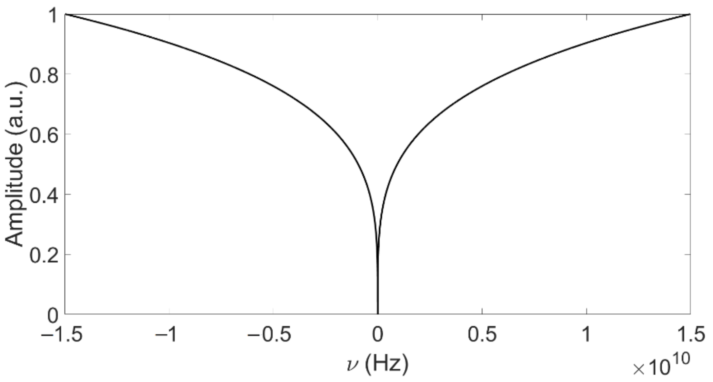
dependence; essentially, a high-pass filtering in amplitude. For example,
Figure 1 shows the plot of the operator
corresponding to the 0.33-th order derivative. From this figure, it can be noticed that
acts as a high-pass filter, with zero reflection at the signal’s central frequency
.
As mentioned in the Introduction, an all-optical in-fiber device can perform a fractional differentiation. Usually, this device consists of a grating with a discrete phase shift inserted at a specific location inside the grating [
6], which indicates either a pointwise change in the fiber core’s refractive index or a spatial shift of the fiber with respect to the phase mask [
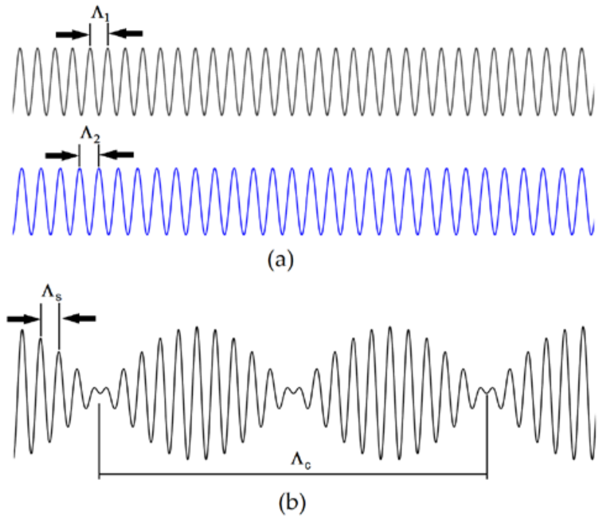
19]. The phase-shifted structure can be recreated as a Moiré grating, though, by superimposing two gratings with equal amplitude but different periods,
and
[
12]. This structure has rapidly and slowly varying envelopes, whose periods are
and
, respectively, as shown in
Figure 2.
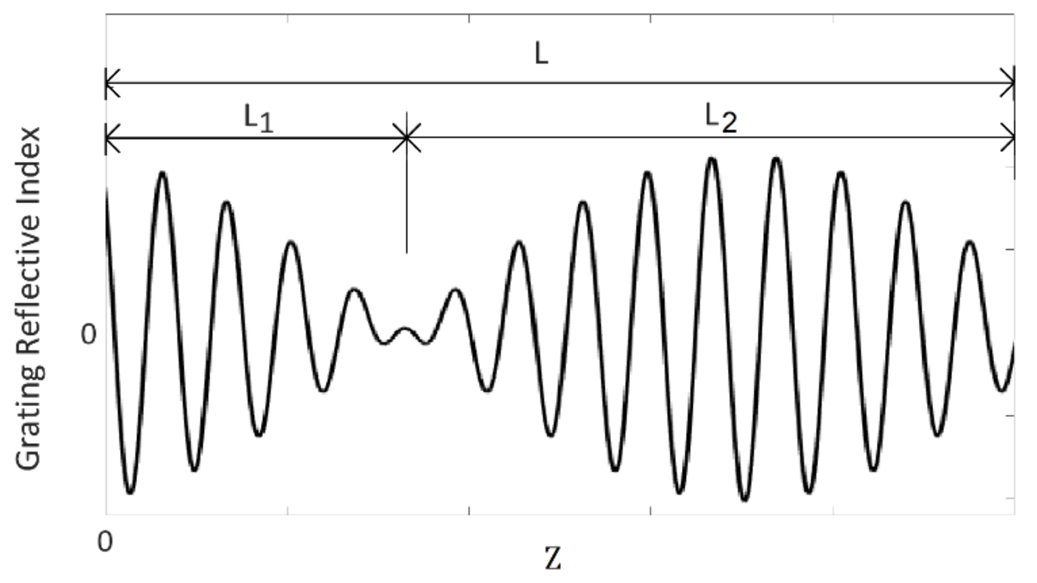
To obtain a fractional differentiator, an asymmetric Moiré grating operated in reflection can be used [
7]. In our case,
Figure 3 shows the asymmetric crossover point of the envelope in the case of an arbitrary phase shift. The required spectral response is obtained by using different grating lengths on either side of the intrinsic phase shift,
, i.e., the phase shift is achieved naturally when the two gratings are superimposed [
18]. Furthermore, several phase-shift values can be obtained by superimposing gratings of different amplitudes. Many phase shifts can also be achieved by using gratings of different lengths, or by changing the periods
and
while the grating length remains unaltered.
The index of refraction of the grating is written as [
7]
where
is the position along the axis of the fiber. It is important to mention that the phase shift is not associated with a crossing point, as when working with FBGs or LPGs. Here, it is distributed all over the grating, and it is not associated with a punctual defect.
3. Results and Discussion
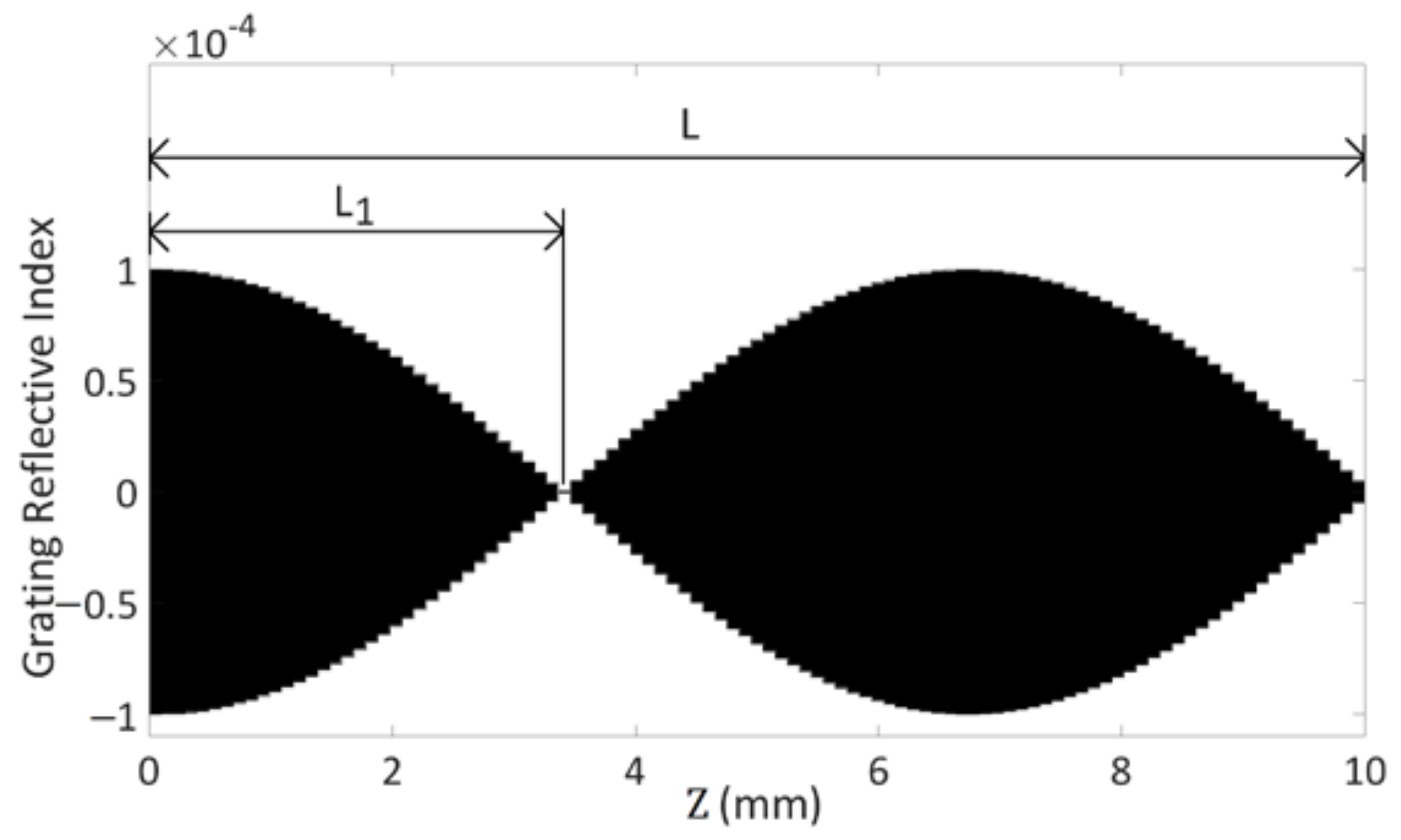
We numerically computed the time-domain response of the proposed AMFG to show how it can be used for fractional differentiation. As a typical example,
Figure 4 shows the refractive index modulation of the AMFG for 0.51th-order fractional differentiation simulated with OptiGrating 4.2.2 software, and it can be seen that the profile has the fish shape as in ref. [
12]. The simulated length of the fiber grating was
, which is associated with the desirable bandwidth. The index modulation depth was
, the rapidly varying envelope (the period of the fiber grating) was
, the slowly varying envelope was
, and the apodization was defined as
where
. It is important to mention that in
Figure 4, only the slowly varying envelope is visible. Individual stripes are not visible in the figure because the rapidly varying period is very small, i.e.,
[
23].
It is commonly known that when the fiber grating’s crossover point is in the center (i.e.,
), it performs a derivative of first-order,
. Recently, Liu et al. [
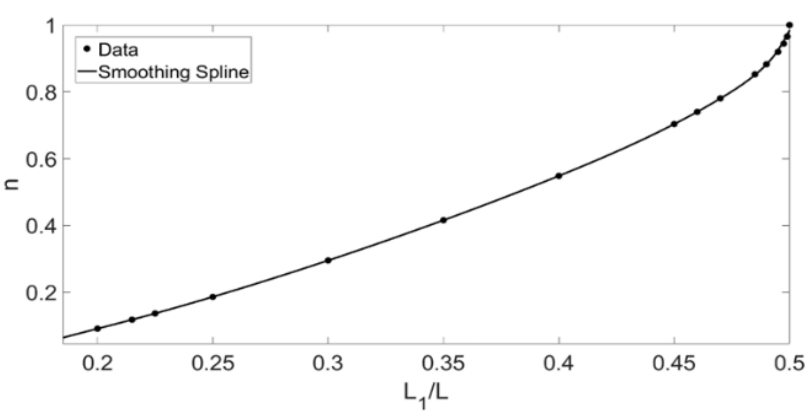
21] demonstrated that all-optical temporal differentiation based on a MFG operated in reflection with only one crossover point at the center of the fiber acts as the first-order temporal differentiator. Furthermore, these authors also demonstrated that a MFG incorporating two symmetrical crossover points acts as the second-order temporal differentiator. To prove that the proposed AMFG can perform the non-integer temporal fractional differentiation,
Figure 5 shows the
n-th order derivative as a function of the relative grating length
. In this last figure, it can be seen that the relation between both parameters is monotonically increasing. Therefore, when
, the AMFG acts as a non-integer temporal fractional differentiator.
In addition, a simulation of an optical signal going through the designed differentiator was performed. The pulse’s waveform was selected to be a transform-limited Gaussian pulse, therefore its expression may be written as:
where
is the pulse half width at the intensity point
, and was chosen as 31.25 ps. The bandwidth of the reflection dip was chosen to be wider than the bandwidth of the initial pulse, and the center frequency was set equal to the frequency of the minimum reflection point.
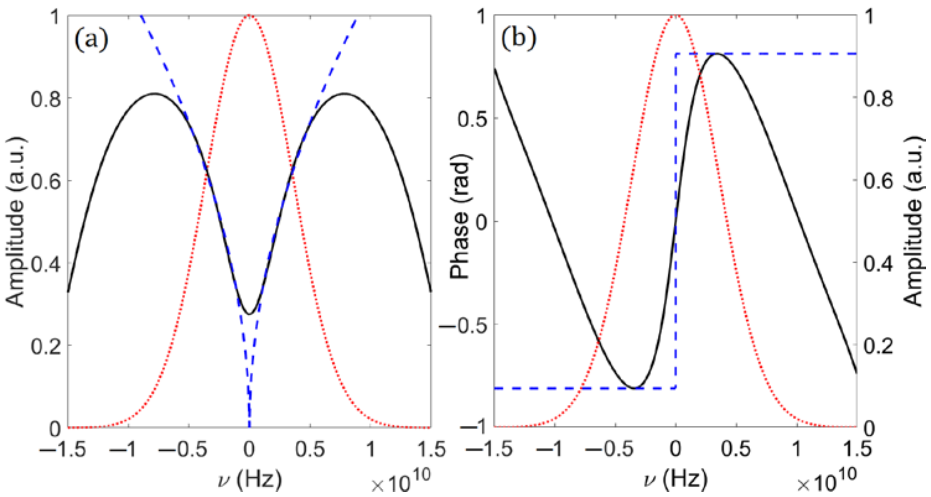
Figure 6a,b depict the reflectivity in amplitude and phase, respectively, as compared with the ideal transfer function
, and the amplitude of the Fourier transform of the pulse to be fractionally differentiated. On the one hand, it should be noted from
Figure 6a that there is a reasonable degree of similarity between the spectral amplitudes (ideal and proposed). In addition, Oppenheim and Lim [
24] found that the Fourier representation of signals preserves many of the important characteristics of a signal if only the phase is preserved. Furthermore, when the signal is of finite length, phase information alone is sufficient to completely reconstruct a signal within a scale factor. On the other hand,
Figure 6b also shows a good agreement between the ideal and proposed phases. From this last figure, it can be seen that the phase shifts of both the ideal and the proposed 0.51th-order differentiator are 0.51 π, except for the presence of a slope for the proposed differentiator. However, from Fourier transform theory, the addition of a slope in phase induces a temporal delay, according to
.
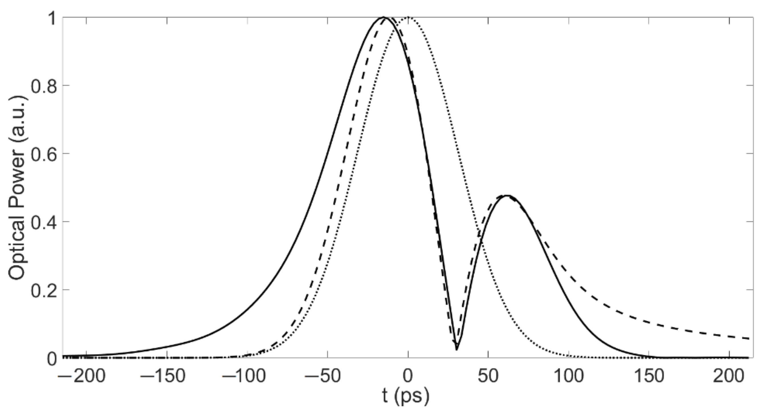
Figure 7 depicts the simulation result of the temporal response of the 0.51th-order differentiator. By multiplying the initial pulse and the spectral response of the AMFG, the differentiated time waveform was extracted from the output spectrum of the AMFG using the inverse Fourier transform. For comparison, the original input signal and the ideal (analytical) time derivative are also shown. In addition, all signals have been normalized to unity to facilitate comparison between them. From this last figure, it can be seen that there is a reasonable degree of agreement between the obtained time profile and the theoretical time derivative of the input pulse.
To enable a quantitative analysis, we used a similar approach as in [
7], by using the following dimensionless deviation factor
where
represents the output of the proposed
n-th-order temporal differentiator, while
is the theoretical time derivative of
n-th-order. The deviation factor for this case is
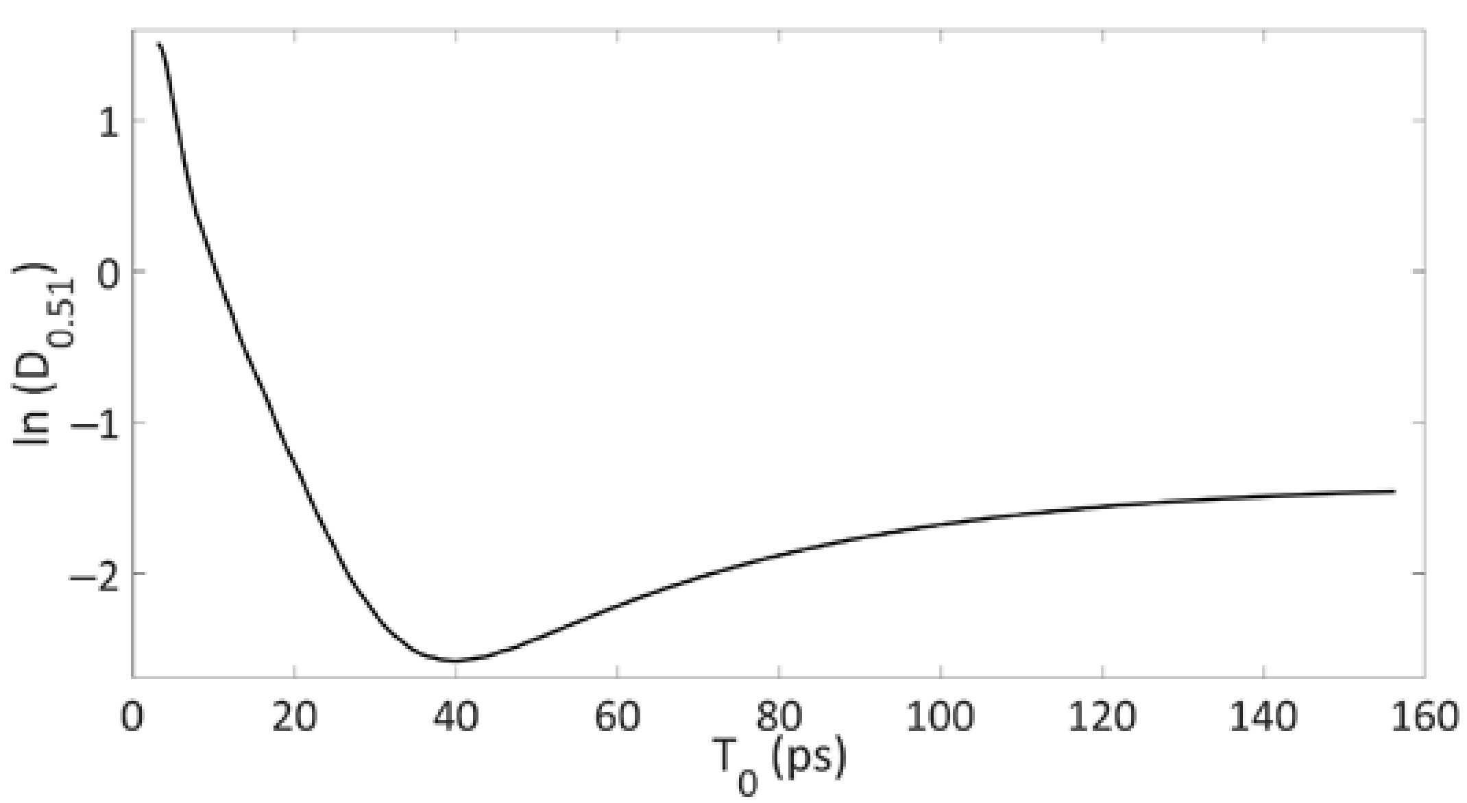
. To demonstrate how sensitive this configuration is to a change in the input signal’s bandwidth T
0,
Figure 8 shows the natural logarithm of the deviation factor (
). For this purpose, several input signals with time widths in the range of 5 ps to 155 ps and the same 0.51th-order differentiator as before were used. In this last figure, it can be seen that the minimum occurs when the time width is close to 40 ps, and that the deviation factor is not significantly increased by a small input bandwidth detuning. It should also be considered that the transmission drop is not exactly zero (see
Figure 6a). Therefore, low-frequency components are not sufficiently rejected. In addition, the phase shift occurred over a bandwidth of 0.8 GHz (see
Figure 6b), which represents 9% as compared with the FWHM (full-width at half maximum) of the Fourier transform of the pulse under test. It is important to mention that the length of the grating
is related to the bandwidth. Generally, shorter devices (i.e., with shorter lengths) can process higher bandwidths [
7].
Although in the Introduction it was stated that the fabrication of an AMFG is simple, in order to analyze the performance of the proposed fractional differentiator, we have also simulated the situation when the two uniform fiber Bragg gratings with slightly different periods have different amplitudes. In this case, the amplitude of one Bragg grating was simulated to be 10% larger than the other one. In this case, there was found a shift in the fractional differentiation order, obtaining
n = 0.55, instead of 0.51. This is a 4% difference in the fractional order differentiation.
Figure 9 shows the simulation result of the temporal response of the 0.55th-order differentiator. For comparison, the original input signal and the ideal (analytical with
n = 0.51) time derivative are also shown, and all signals have been normalized to unity to facilitate the comparison between them. In this last figure, it can be seen that there is still a reasonable degree of agreement between the obtained time profile and the theoretical time derivative of the input pulse, in spite of the shift in the differentiator order.
Furthermore, it is known from
Figure 5 that the fractional differentiation order
n is determined precisely by the value of
. As the curve of the refractive index modulation of the grating is invisible, it is difficult and sometimes impossible to measure
and
precisely. However, they can be determined by measuring the spectral response once it is fabricated.
Finally, these devices have several practical applications. For example, they can be used for instantaneous frequency detection based on the use of a 0.5th-order in-fiber fractional calculus differentiator, as was proved theoretically in [
25], and later experimentally in [
26].


