

Leading Edge Bumps for Flow Control in Air-Cooled Condensers †

1
Department of Mechanical and Aerospace Engineering, Faculty of Industrial and Civil Engineering, Sapienza University of Rome, Via Eudossiana 18, 00184 Rome, Italy
2
Department of Mechanical & Mechatronic Engineering, Faculty of Mechanical Engineering, Stellenbosh University, Private Bag X1, Cape Town 7602, South Africa
*
Author to whom correspondence should be addressed.
†
This paper was published in the Proceedings of the 18th Conference on Modelling Fluid Flow (CMFF’22), Budapest, Hungary, 30 August–2 September 2022.
Int. J. Turbomach. Propuls. Power 2023, 8(1), 9; https://doi.org/10.3390/ijtpp8010009
Submission received: 16 January 2023
/
Revised: 1 March 2023
/
Accepted: 7 March 2023
/
Published: 9 March 2023
(This article belongs to the Special Issue Selected Turbomachinery Papers from the 18th Conference on Modelling Fluid Flow CMFF'22)
Abstract
:Air-cooled condensers (ACCs) are commonly found in power plants working with concentrated solar power or in steam power plants operated in regions with limited water availability. In ACCs, the flow of air is driven toward the heat exchangers by axial fans that are characterized by large diameters and operate at very high mass flow rates with a near-zero static pressure rise. Given the overall requirements in steam plants, these fans are subjected to inflow distortions, unstable operations, and are characterized by high noise emissions. Previous studies show that leading edge bumps in the tip region of axial fans can effectively reduce the sound pressure levels without affecting the static efficiency. Nevertheless, the effects of this treatment in terms of flow patterns and heat exchange in the whole ACC system were not investigated. In this work, the effect of leading edge bumps on the flow patterns is analyzed. Two RANS simulations were carried out using OpenFOAM on a simplified model of the air-cooled condenser. The fans are simulated using a frozen rotor approach. Turbulence modeling relies on the RNG k-epsilon model. The fan is characterized by a diameter of 7.3 m and a 333 m3/s volumetric flow rate at the design point. The presence of the heat exchanger is modeled using a porous medium. The comparison between the flow fields clearly exerts that the modified blade is responsible for the redistribution of radial velocities in the rotor region. This drastically reduces the losses related to the installation of the fan in a real configuration.
1. Introduction
Condensers in steam power plants can be either water- or air-cooled. Usually, the first solution is preferred because it guarantees a higher overall efficiency, given the lower ancillary operational costs involved, and is a more compact solution. However, some power plants require air-cooled condensers, usually because of the lack of cooling water near the installation site. That is the case for concentrated solar power (CSP) plants with a bottoming Rankine cycle, as CSP plants are commonly installed in desertic areas, or for large steam plants such as [1], which are installed in desertic areas near largely populated cities.
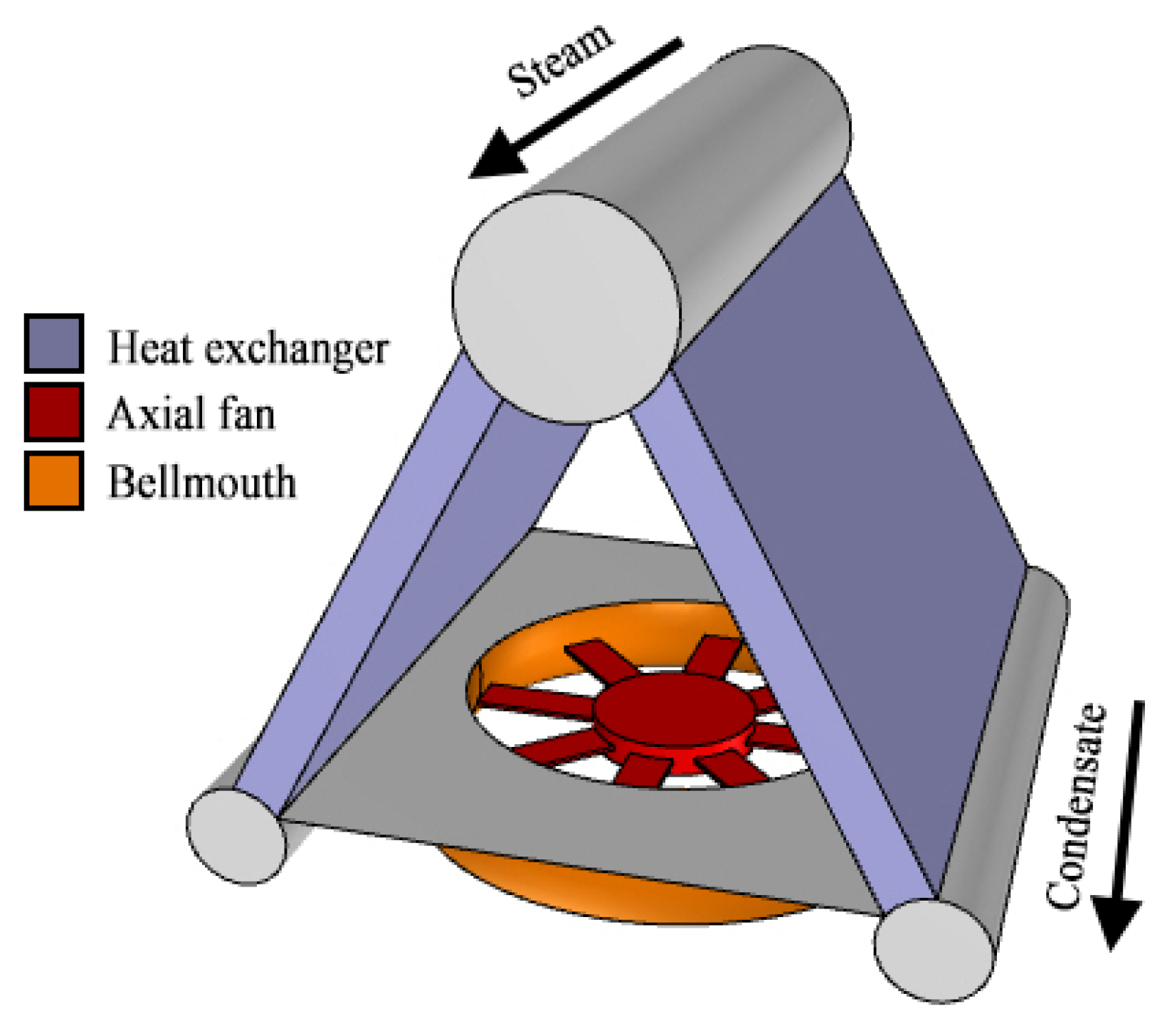
For this work, we will refer to air-cooled condensers (ACCs) and their typical arrangement, in particular the design of fans inside these units. The ACC assembly comprises a series of cooling units (>400 in a power plant) where large axial fans feed fresh air to a series of heat exchangers, where the steam condensates. The typical arrangement, shown in Figure 1, is that of an A-frame condenser unit with the fan inlet placed several meters above the ground and the heat exchangers on top of the fan.
These fans are operated with very high volume flow rates (250 to 400+ m3/s) and a very low static pressure rise (100 to 300 Pa). This unusual combination results in a design characterized by a large diameter (6–12 m), a low hub-to-tip ratio (0.25–0.4), and a rotational velocity between 100 and 200 rpm. Being so large and mounted on very high (>30 m) structures to provide a sufficiently wide inflow, these fans are often characterized by a large and irregular tip clearance due to assembly issues that eventually reflect the fan efficiency [2].
The operations of these fans are also critical, as their efficiency drops when working with a lateral wind condition, in sandy environments, or with extreme environmental temperatures. In these conditions, the volume dilatation of the structures can in fact, significantly impact the tip gap, with possible effects on fan efficiency, vibrations, mechanical failures, and noise emissions. Noise is in fact one of the problems of large ACCs due to the high number of fans involved [3,4].
Among the possible strategies available to fan designers to tackle part of these problems, sinusoidal leading edges were proposed to control the trailing edge separation, the evolution of the tip leakage vortex, and the noise. Developed from biomimicry assumptions on the hydrodynamics of humpback whale fin tubercles [5], these leading edge modifications were found to change the dynamics of separation and loss of lift capabilities in NACA four-digit modified airfoils. The control mechanism was associated with counter-rotating vortex pairs shed from the serrations of the leading edge. At very high angles of attack (i.e., when the airfoil stalls), this vortex pair is responsible for controlling trailing edge separation and, in particular, limiting it in the region of the trailing edge that corresponds to the troughs of the leading edge sinusoid. Later studies, based on unsteady computations, have revealed that a secondary motion arises in the spanwise direction, with secondary phenomena resulting in a secondary shedding frequency that involves the whole blade span [6]. The separation control capability of leading edge serrations was exploited in modified axial fan geometries to control the development of the tip leakage vortex along the suction side of the rotor, resulting in controlled stall dynamics [7]. Moreover, when dealing with noise, experimental and numerical findings [8,9] show how sinusoidal leading edges result in a change in the acoustic signature of the fan.
In the framework of the H2020 MinwaterCSP [10], we designed a fan for ACCs that is now in operations at the Stellenbosh University. This fan is running in an ACC unit in real conditions and is characterized by limitations that can result in distorted inflow conditions and a reduction in the volume flow rate. This is a consequence of the nearby university buildings and of a water channel that flows below the test rig. Among the MinwaterCSP requirements for this fan, limiting the noise emissions was a key factor, as in real ACCs, the sound emissions from hundreds of units pose health issues for people and fauna. In this case, however, the real problem comes from the proximity of the university and the presence of staff and students. For these reasons, a preliminary study of the effects of the modified geometry on the aerodynamics of this fan is presented here.
2. Numerical Methodology
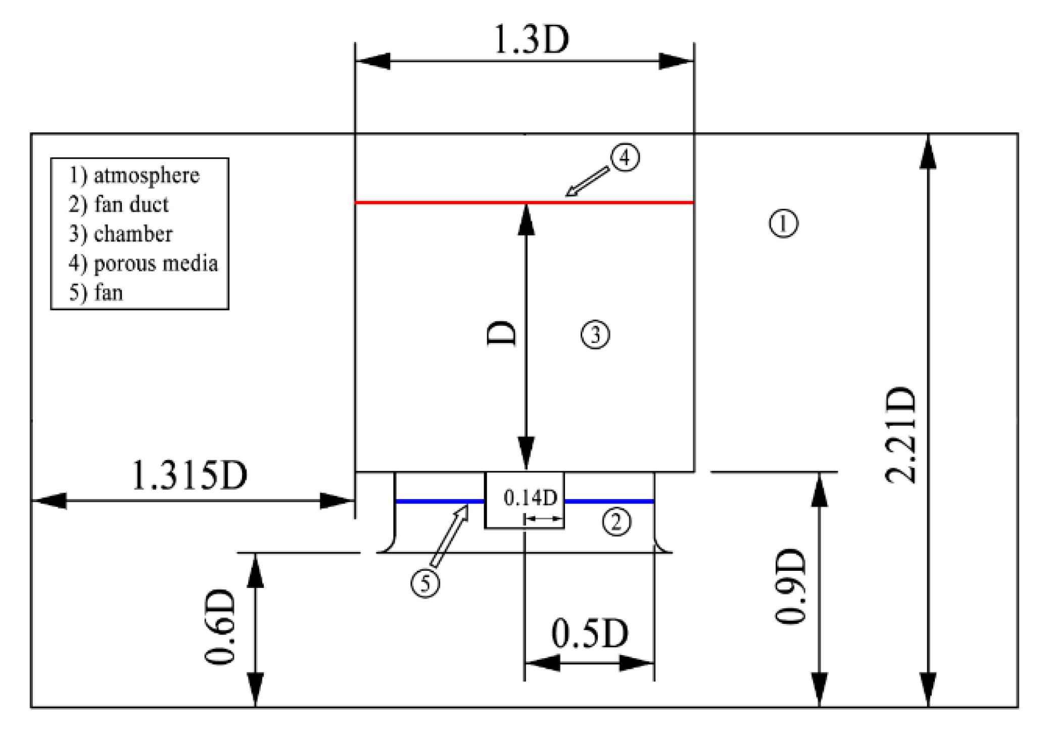
The computational domain is chosen based on the experimental apparatus that is described in [2]. It describes a full-scale A-type air-cooled condenser [11]. This ACC experimental configuration includes a grid downstream of the fan, which was modeled using a porous medium.
The structural supports to the exchanger are not included in the final model, their effect being minimal from an aerodynamic point of view. The domain, which is normalized by the rotor diameter D, is reported in Figure 2. The domain is symmetric with respect to the fan; therefore, each of the four lateral boundaries is located at 1.315 D from the exchanger walls.
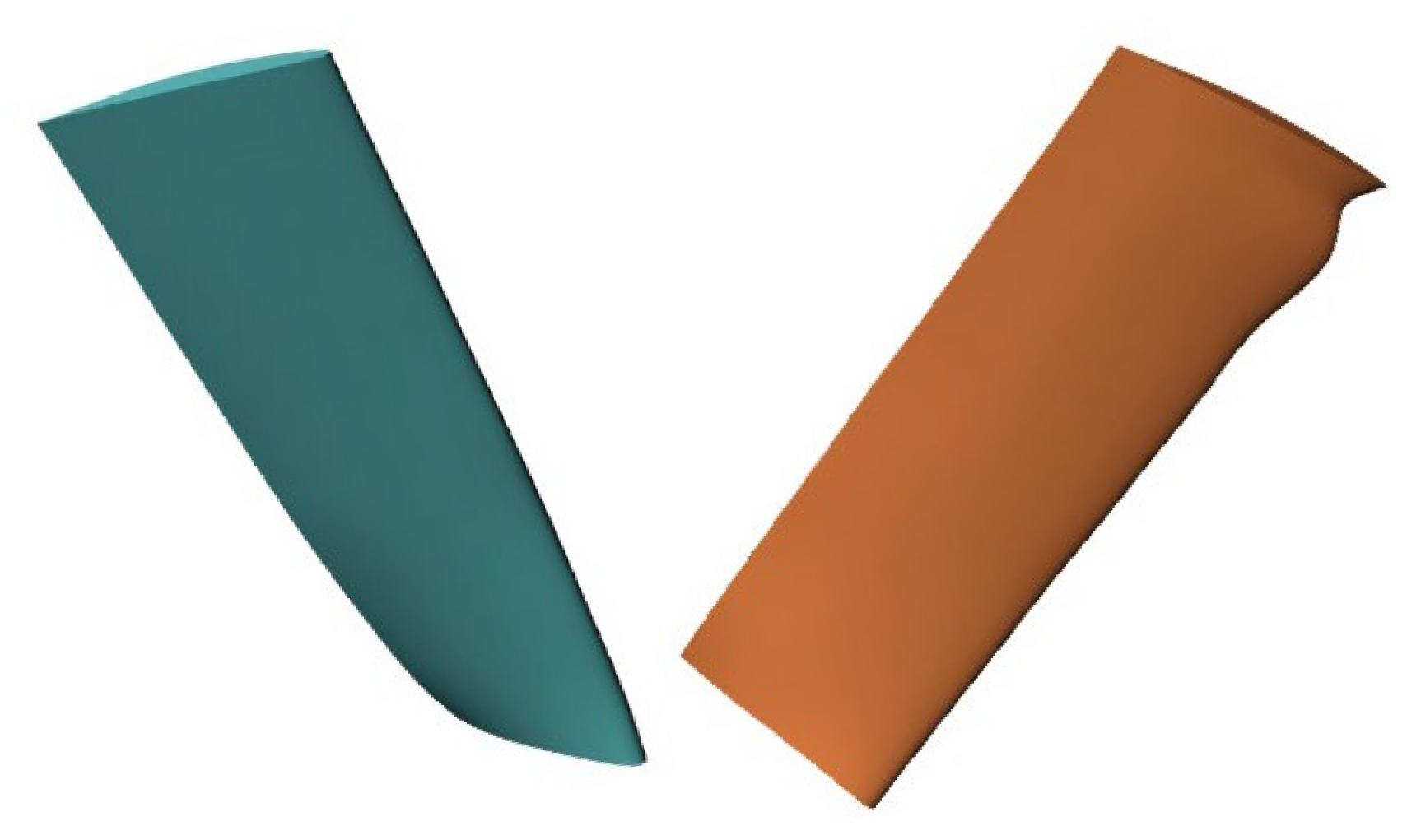
The fan is an eight-blade low-speed axial fan. Rotor diameter is 7.3 m, with a hub-to-tip ratio equal to 0.284. Tip clearance is set to 0.2% of the blade tip chord. Blade tip chord and chord-based Reynolds numbers are 825 mm and 4.65 × 10⁵, respectively. The rotational speed of the fan is 151 rpm. The fan provides 105 Pa of total-to-static pressure at the nominal volumetric flow rate of 333 m3/s. The design process of both the fan and its modified version are reported in [12]. The leading edge bumps are designed by varying the blade chord of +/−5%, following a sinusoidal law in the outer 25% of the blade span. The original blade, here labeled as datum fan, and its modified version, here labeled as whale fan, are shown in Figure 3.
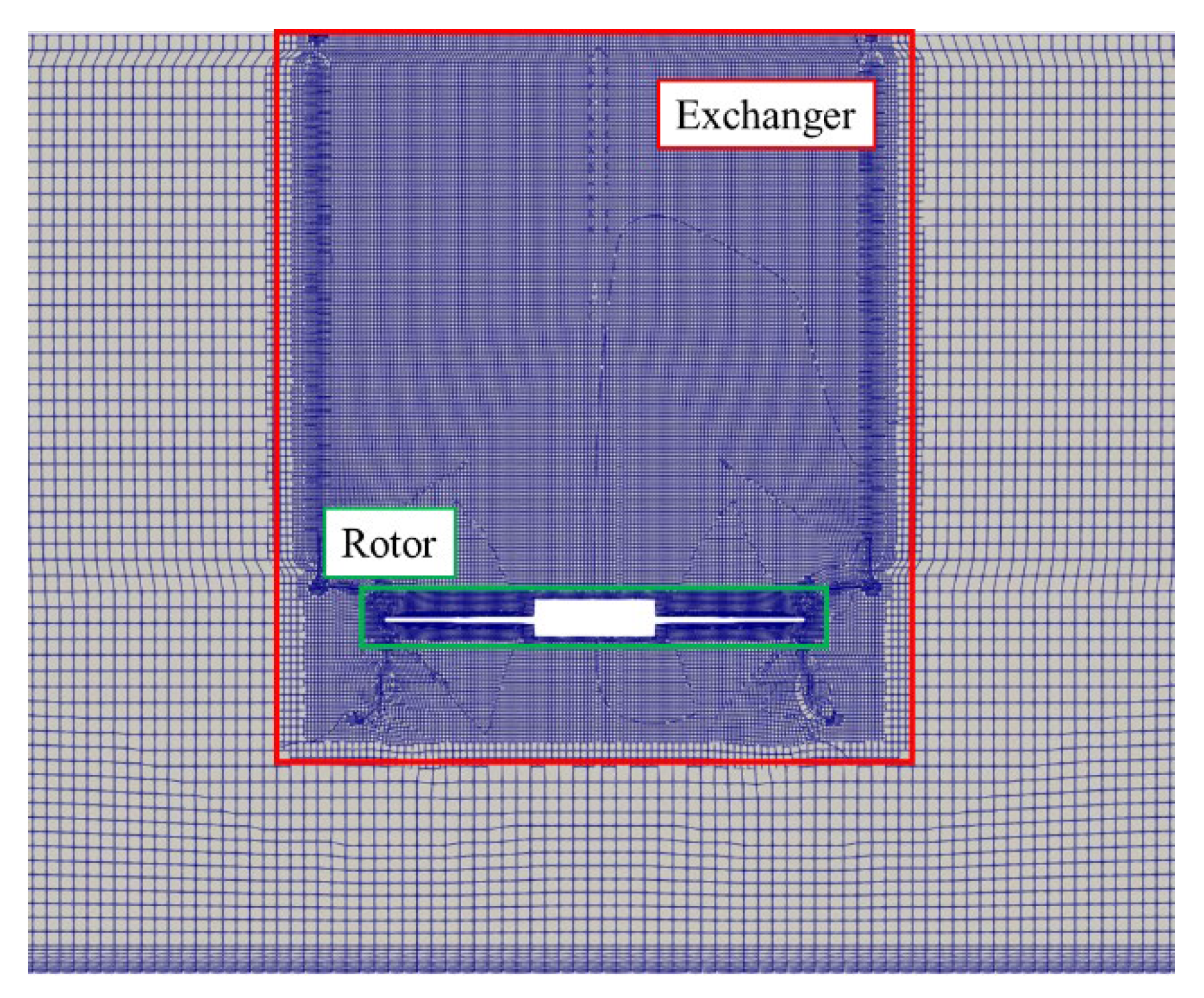
The computational grid was generated for both geometries using the snappyHexMesh utility of the OpenFOAM v2106 library. The base grid entails 0.8 million cells with unity aspect ratio and a cell size of approximately 0.13 m. The grid is sequentially refined in the whole exchanger and in the rotor region, as shown in Figure 4.
Due to the large computational domain, the grid was designed for high Reynolds computation. Therefore, the wall spacing was set to achieve a y+ = 100 on the first layer of cells.
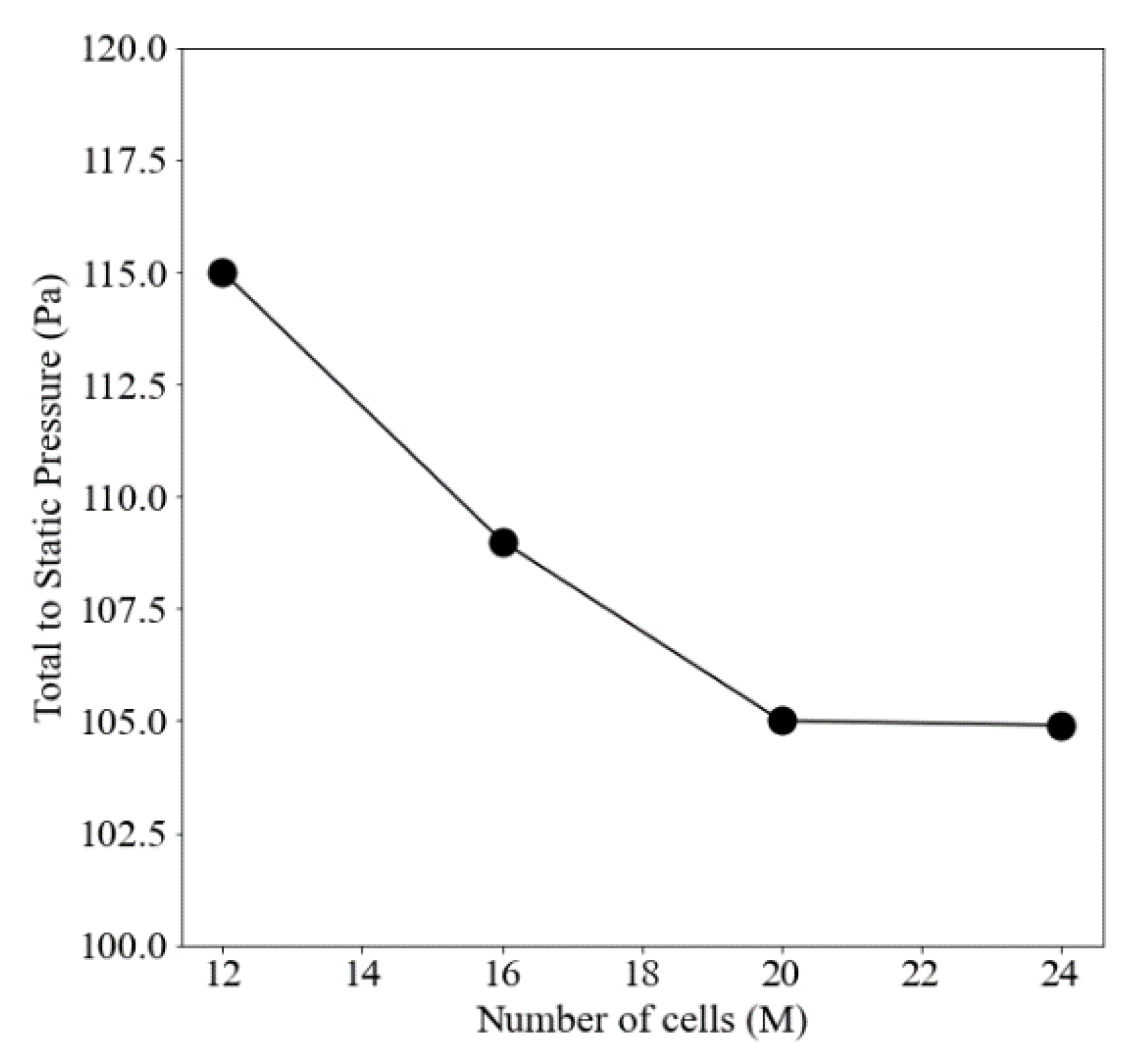
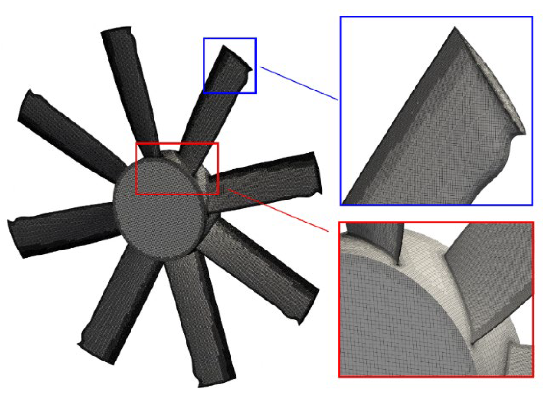
A grid sensitivity analysis on the datum fan configuration was performed using total-to-static pressure rise as convergence parameter. Results are shown in Figure 5, showing that a grid refinement of 20 million cells is sufficient for this setup. Two million cells are used to model the external atmosphere, 15 million in the rotor region, and 3 million in the heat exchanger. A visualization of the grids on the whale fan rotors is provided in Figure 6.
The porous medium is modeled using the Darcy–Forchheimer relationship for the pressure drop in the heat exchanger:
This pressure gradient acts as sink term in the momentum equation. The coefficients of Equation (1) were derived from the geometry of the squared grid in the test rig, which has a characteristic length of 5 cm, following the methodology reported in [13]. Since the flow is characterized by a predominant axial direction, the coefficients in orthogonal directions are set to 1010.
Turbulence modeling relies on the RNG k-epsilon model [14]. The steady computations are based on a frozen rotor approach and the incompressible equations are solved using the SIMPLE solver. Convergence was assessed by the torque of the fan and the velocity in probes upstream and downstream of the fan. The linearized systems of equations were solved using a smoothSolver for all the quantities except for pressure, which was solved using a conjugate gradient solver. Tolerance for convergence was set to 10−6 for all quantities except pressure, which was set to 10−4.
A scheme of the boundary conditions is shown in Figure 7. The ground is treated as a rough wall, with relative thickness of 0.1. The mass flow rate is imposed on the lateral boundaries, which is equal to 25% of the duty point of the fan. Atmosphere is treated as a slip wall for numerical stability of the simulation. At the outflow of the fan, total pressure is imposed, with zero gradient (zG) condition on velocity. On all solid surfaces, standard wall functions for turbulent kinetic energy, its dissipation rate, and turbulent viscosity are used.
3. Results
As a validation assessment of the accuracy of computations, a comparison of the TTS pressure and TTS efficiency is shown in Table 1. The pressure is averaged over two planes at 1.6 D and 1.8 D from the ground. The results show that the pressure rise capability of the two fans in ISO conditions is practically the same, with a slightly worst efficiency for the whale fan, confirming the conclusions in [15]. However, the installation inside the ACC setup leads to different behaviors: the datum geometry in fact shows a reduction in the pressure rise capability of 32%, with a negligible change in power adsorbed, while the whale fan has a reduction in both the pressure rise and power consumption of about 10%.
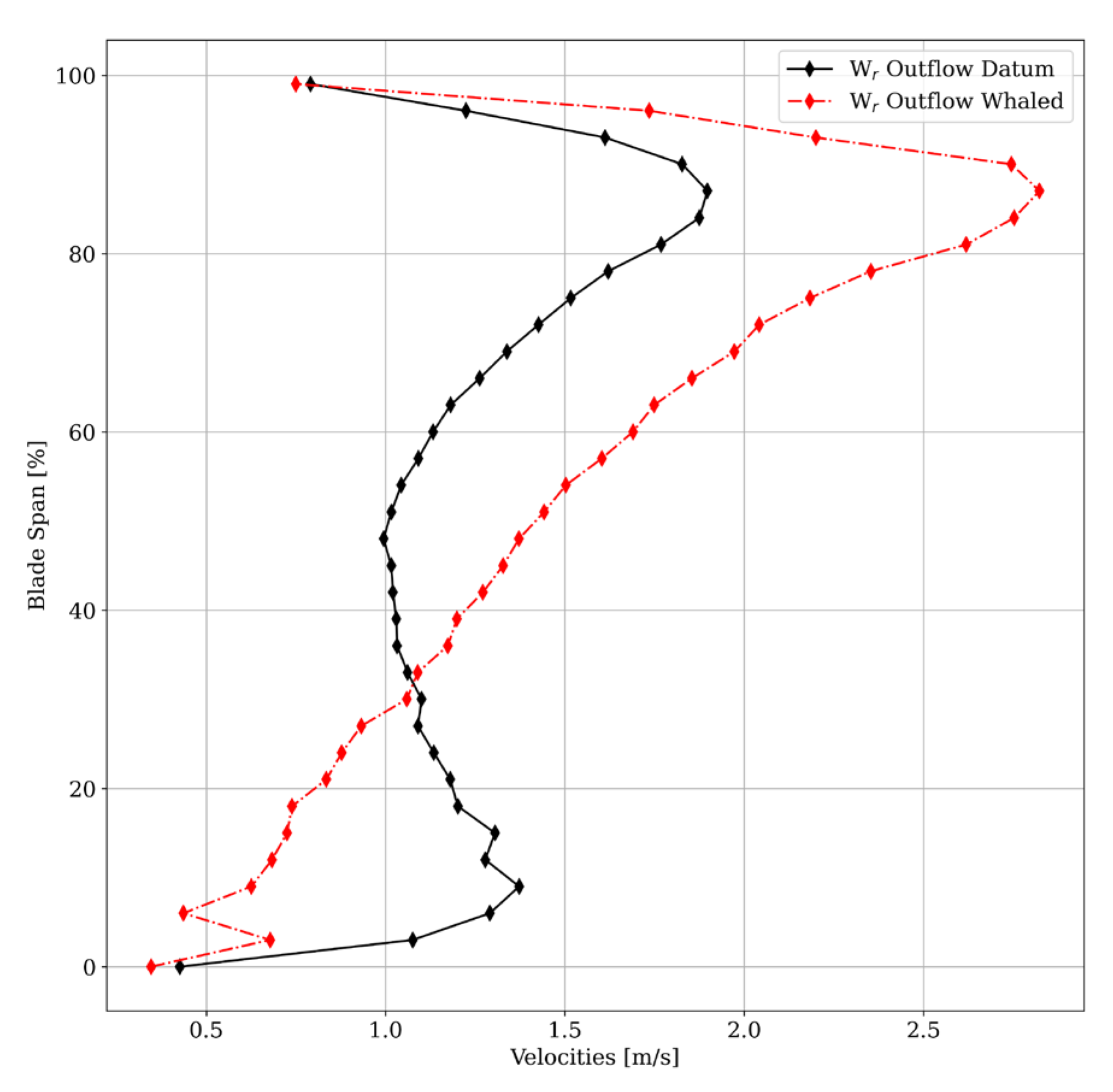
This change in performance is associated with a higher work capability in the tip region and a change in the spanwise behavior of the flow. This is shown in Figure 8, where the whale fan shows a linear trend from root to 85% of the span, while the datum geometry has a higher radial velocity value at the root of the blade and then a lower value from 1/3 of the blade span.
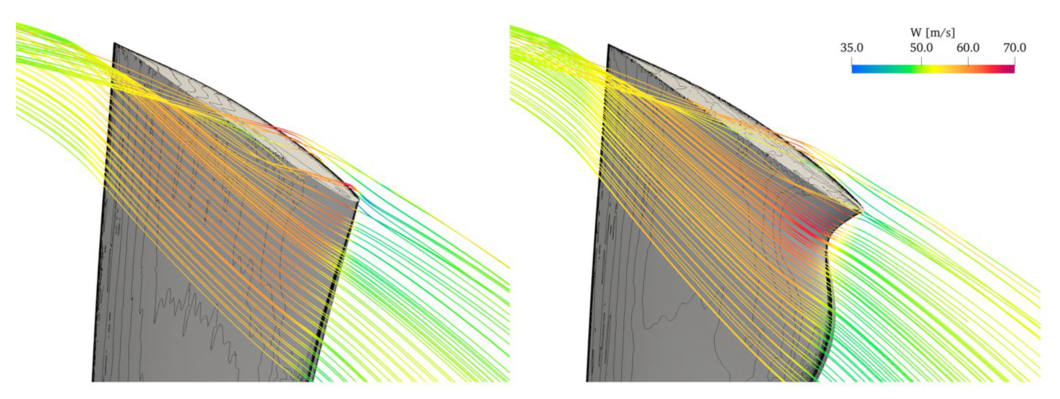
The change in performance can be associated mainly with the effect of the leading edge modification on the development of the tip leakage vortex. As shown in Figure 9, in fact, at the tip of the sinusoidal leading edge, the flow accelerates and reaches a relative velocity of over 70 m/s. The resulting jet released by this region of the rotor delays the development of the tip leakage vortex with respect to the datum fan. In fact, in the datum geometry, the leaking starts at about 10% of the chord of the tip section, with a secondary vortex released at about 50% of the chord.
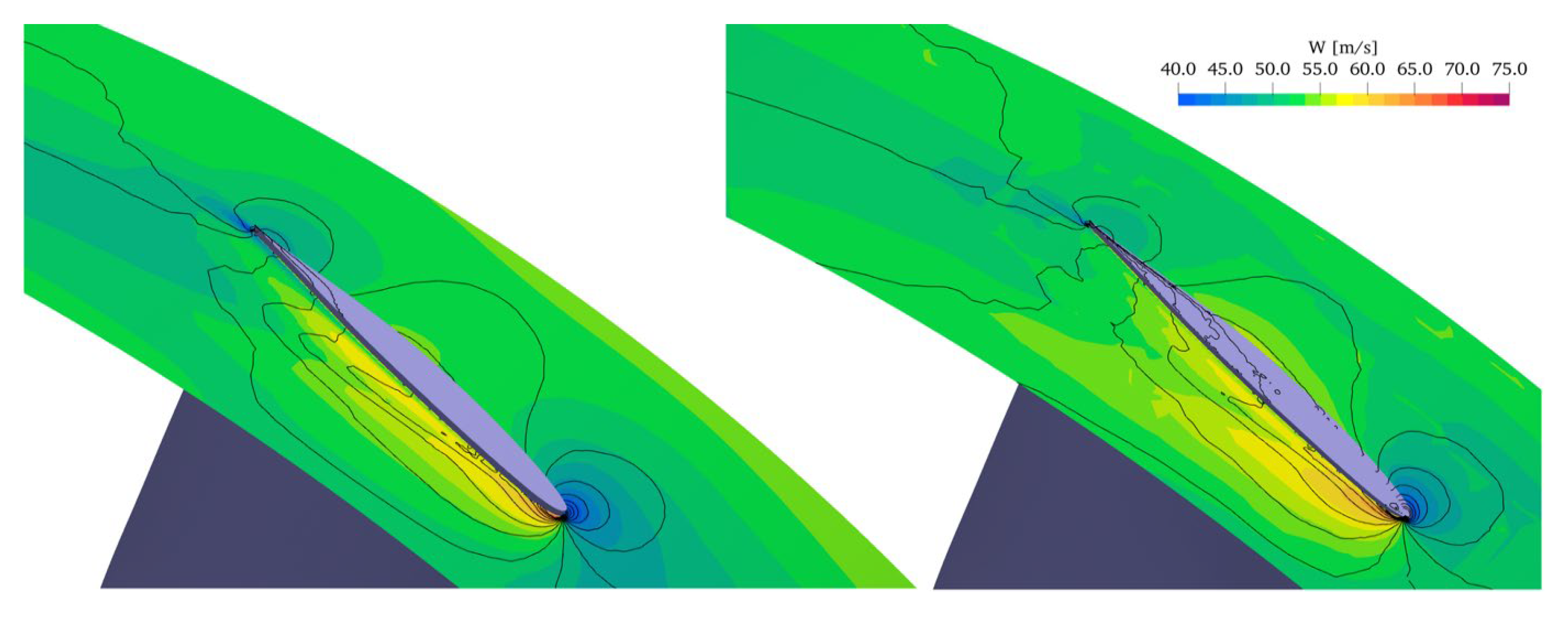
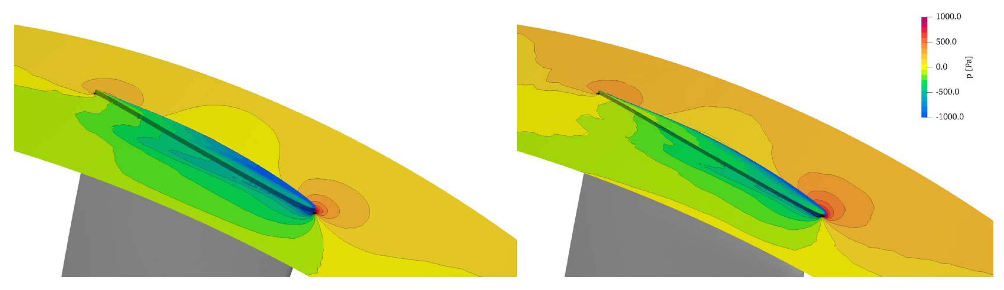
On the whale rotor, only this second structure is present, due to the counter rotating flow released by the modified leading edge that blocks the development of the first leaking structure. This is better seen in Figure 10 and Figure 11, where the relative velocity and pressure contours are plotted on an iso-radius surface at 99% of the blade span. In both figures, the trace of the tip leakage vortex system is clearly recognizable, with a delayed development for the whale rotor geometry.
4. Conclusions
Following the conclusions of previous works on modified fan rotors with sinusoidal leading edges, we tested this flow control solution on an air-cooled condenser fan for steam power plants.
In an ISO arrangement, the original blade and the whale blade have similar performances in both the total-to-static pressure rise capability and adsorbed power. When fitted in the ACC, however, there is a clear improvement, as the whale fan experiences a loss of pressure rise with respect to the ISO arrangement of about 11%, compared to a loss of 32% for the datum blade. Additionally, the absorbed power is reduced by 10%, while the datum fan experiences a negligible difference with respect to the ISO conditions.
The different behavior was then related to a radial redistribution of the flow induced by the modified rotor and its capability to control and contrast the development of the tip-leakage vortex on the suction side of the rotor. These findings are similar to those shown in [5].
Author Contributions
Conceptualization, L.T., G.D., J.v.d.S. and A.C.; Methodology, L.T., G.D., J.v.d.S. and A.C.; Software, L.T., G.D., J.v.d.S. and A.C.; Validation, L.T., G.D., J.v.d.S. and A.C.; Formal Analysis, L.T., G.D., J.v.d.S. and A.C.; Investigation, L.T., G.D., J.v.d.S. and A.C.; Resources, L.T., G.D., J.v.d.S. and A.C.; Data Curation, L.T., G.D., J.v.d.S. and A.C.; Writing—Original Draft Preparation, L.T., G.D., J.v.d.S. and A.C.; Writing—Review & Editing, L.T., G.D., J.v.d.S. and A.C.; Visualization, L.T., G.D., J.v.d.S. and A.C.; Supervision, L.T., G.D., J.v.d.S. and A.C.; Project Administration, L.T., G.D., J.v.d.S. and A.C.; Funding Acquisition, L.T., G.D., J.v.d.S. and A.C.; All authors have read and agreed to the published version of the manuscript.
Funding
This research received no external funding.
Data Availability Statement
Data, geometry and numerical setup are available upon request to the authors.
Conflicts of Interest
The authors declare no conflict of interest.
References
- Fourie, N.; Van Der Spuy, S.J.; Von Backström, T.W.; Van Der Spuy, S. Simulating the Effect of Wind on the Performance of Axial Flow Fans in Air-Cooled Steam Condenser Systems. J. Therm. Sci. Eng. Appl. 2015, 7, 021011. [Google Scholar] [CrossRef] [Green Version]
- Van der Spuy, S.J.; Els, D.N.J.; Tieghi, L.; Delibra, G.; Corsini, A.; Louw, F.G.; Zapke, A.; Meyer, C.J. Preliminary Evaluation of the 24 Ft. Diameter Fan Performance In the MinWaterCSP Large Cooling Systems Test Facility. In Turbo Expo: Power for Land, Sea, and Air; American Society of Mechanical Engineers: New York, NY, USA, 2021; p. V001T10A005. [Google Scholar]
- Van der Spuy, S.J.; von Backström, T.W.; Kröger, D.G. Performance of low noise fans in power plant air cooled steam condensers. Noise Control Eng. J. 2009, 57, 341–347. [Google Scholar] [CrossRef] [Green Version]
- Angelini, G.; Bonanni, T.; Corsini, A.; Delibra, G.; Tieghi, L.; Volponi, D. On Surrogate-Based Optimization of Truly Reversible Blade Profiles for Axial Fans. Designs 2018, 2, 19. [Google Scholar] [CrossRef] [Green Version]
- Corsini, A.; Delibra, G.; Sheard, A.G. On the Role of Leading-Edge Bumps in the Control of Stall Onset in Axial Fan Blades. J. Fluids Eng. 2013, 135, 0811041–0811048. [Google Scholar] [CrossRef]
- Zhang, M.M.; Wang, G.F.; Xu, J.Z. Aerodynamic control of low-Reynolds-number airfoil with leading-edge pro-tuberances. AIAA J. 2009, 51, 1960–1971. [Google Scholar] [CrossRef]
- Corsini, A.; Delibra, G.; Sheard, A.G. The application of sinusoidal blade-leading edges in a fan-design methodology to improve stall resistance. Proc. Inst. Mech. Eng. Part A J. Power Energy 2014, 228, 255–271. [Google Scholar] [CrossRef]
- Biedermann, T.M.; Kameier, F.; Paschereit, C.O. Successive Aeroacoustic Transfer of Leading Edge Serrations From Single Airfoil to Low-Pressure Fan Application. J. Eng. Gas Turbines Power 2019, 141, 101011. [Google Scholar] [CrossRef]
- Biedermann, T.M.; Chong, T.P.; Kameier, F.; Paschereit, C.O. Statistical–Empirical Modeling of Airfoil Noise Subjected to Leading-Edge Serrations. AIAA J. 2017, 55, 3128–3142. [Google Scholar] [CrossRef]
- The MinWaterCSP Project. Available online: http://www.minwatercsp.eu (accessed on 16 January 2023).
- Kirstein, C.F.; Von Backström, T.W.; Kröger, D.G. Flow Through a Solar Chimney Power Plant Collector-to-Chimney Transition Section. In Proceedings of the ASME 2005 International Solar Energy Conference, Orlando, FL, USA, 6–12 August 2005; pp. 713–719. [Google Scholar] [CrossRef] [Green Version]
- Volponi, D.; Bonanni, T.; Tieghi, L.; Delibra, G.; Wilkinson, M.; van der Spuy, J.; von Backström, T. CFD Simulation Results for the MinWaterCSP Cooling Fan. In Proceedings of the Fan 2018–International Conference on Fan Noise, Aerodynamics, Applications and Systems, Darmstadt, Germany, 18–20 April 2018. [Google Scholar] [CrossRef]
- Idelchik, I.E. Handbook of Hydraulic Resistance; U.S. Atomic Energy Commission: Washington, DC, USA, 1986.
- Yakhot, V.; Orszag, S.A.; Thangam, S.; Gatski, T.B.; Speziale, C.G. Development of turbulence models for shear flows by a double expansion technique. Phys. Fluids A Fluid Dyn. 1992, 4, 1510–1520. [Google Scholar] [CrossRef] [Green Version]
- Tieghi, L.; Delibra, G.; Corsini, A.; Van Der Spuy, J. Numerical investigation of CSP air cooled condenser fan. E3S Web Conf. 2020, 197, 11010. [Google Scholar] [CrossRef]
Figure 1.
A-frame arrangement for an ACC unit.

Figure 2.
Front view of the numerical domain.

Figure 3.
Datum (left) and whale (right) fan geometries.

Figure 4.
Grid refinements.

Figure 5.
TTS pressure as a function of the number of cells, datum blade.

Figure 6.
Mesh of the fan and details of the grid at blade tip and hub, whale fan design.

Figure 7.
Scheme of boundary conditions, front view.

Figure 8.
Radial velocity at the outlet of the datum fan (black) and the whale fan (red).

Figure 9.
Relative velocity streamlines on the tip region colored with relative velocity. Left: datum; right: whaled.
Figure 9.
Relative velocity streamlines on the tip region colored with relative velocity. Left: datum; right: whaled.

Figure 10.
Relative velocity contours on iso-radius surface at 99% of the blade span. Left: datum; right: whaled.
Figure 10.
Relative velocity contours on iso-radius surface at 99% of the blade span. Left: datum; right: whaled.

Figure 11.
Relative pressure contours on iso-radius surface at 99% of the blade span. Left: datum; right: whaled.
Figure 11.
Relative pressure contours on iso-radius surface at 99% of the blade span. Left: datum; right: whaled.


Table 1.
Validation of CFD results.
| Geometry | Setup | (Pa) | Power (kW) |
|---|---|---|---|
| Datum | ACC | 95 | 61.7 |
| Single Rotor | 140 | 60.4 | |
| Whale | ACC | 123.8 | 56 |
| Single Rotor | 137.6 | 62 |
Disclaimer/Publisher’s Note: The statements, opinions and data contained in all publications are solely those of the individual author(s) and contributor(s) and not of MDPI and/or the editor(s). MDPI and/or the editor(s) disclaim responsibility for any injury to people or property resulting from any ideas, methods, instructions or products referred to in the content. |
© 2023 by the authors. Licensee MDPI, Basel, Switzerland. This article is an open access article distributed under the terms and conditions of the Creative Commons Attribution (CC BY-NC-ND) license (https://creativecommons.org/licenses/by-nc-nd/4.0/).
Share and Cite
MDPI and ACS Style
Tieghi, L.; Delibra, G.; van der Spuy, J.; Corsini, A. Leading Edge Bumps for Flow Control in Air-Cooled Condensers. Int. J. Turbomach. Propuls. Power 2023, 8, 9. https://doi.org/10.3390/ijtpp8010009
AMA Style
Tieghi L, Delibra G, van der Spuy J, Corsini A. Leading Edge Bumps for Flow Control in Air-Cooled Condensers. International Journal of Turbomachinery, Propulsion and Power. 2023; 8(1):9. https://doi.org/10.3390/ijtpp8010009
Chicago/Turabian StyleTieghi, Lorenzo, Giovanni Delibra, Johan van der Spuy, and Alessandro Corsini. 2023. "Leading Edge Bumps for Flow Control in Air-Cooled Condensers" International Journal of Turbomachinery, Propulsion and Power 8, no. 1: 9. https://doi.org/10.3390/ijtpp8010009