
Exergy-Based Efficiency Assessment of Fans vs. Isentropic Efficiency

Department of Mechanical Engineering, Technische Universität Darmstadt, Otto-Berndt-Straße 2, 64287 Darmstadt, Germany
*
Author to whom correspondence should be addressed.
Int. J. Turbomach. Propuls. Power 2023, 8(1), 4; https://doi.org/10.3390/ijtpp8010004
Submission received: 5 September 2022
/
Revised: 21 December 2022
/
Accepted: 2 February 2023
/
Published: 6 February 2023
(This article belongs to the Special Issue Fan Noise, Aerodynamics, Applications and Systems)
Abstract
:The efficiency definition allows us to compare two machines with each other. In general, the efficiency is defined as the ratio of usable power to the required power. This raises the question: what is the usable power? Most engineers discuss efficiency on the basis of the energy balance, i.e., the first law of thermodynamics. In this paper, we derive the exegetic efficiency taking the second law of thermodynamics into account. Exergy analysis takes into account work and heat and is able to model reality very accurately. On this basis, a comparison between the isentropic and exergetic efficiencies is given. A high-pressure radial fan is used as an example, and the differences are discussed. Therefore, measurements of a non-adiabatic fan are evaluated, and the role of the heat flux in the environment is discussed. The investigations show that a relevant difference between the isentropic and exergetic efficiencies becomes apparent in the partial-load range with high-pressure build-up. The thermal energy contained in the flow belongs proportionally to the exergy, i.e., the working capacity of the gas relative to its environment. For a standard such as ISO 5801 “Fans—Performance testing using standardized airways”, the efficiency must not only be physically correct, it must also be simple and practical. Against this background, the outlook of this paper discusses when and which efficiency definition is appropriate and best suited for a standard.
1. Introduction
Fans and compressors are working machines that are characterized by their wide operating range and their application in every industrial sector. Their fundamental function is to deliver a volume flow of a fluid at a given pressure difference, which makes them essential for all kinds of industrial processes from simple compressed air supply to highly complex chemical reactions. Most diverse application-related requirements and gases lead to a variety of machine designs. In this regard, the physical working principles give a reasonable structure to the fans and compressors. For today’s technical applications, the two most relevant principles are the hydrodynamic and hydrostatic principles. The associated machine categories are turbomachines and positive displacement machines. In this paper we focus on the application of fans.
Besides the importance of fans and compressors for the implementation of industrial processes, their use causes costs. These costs mainly depend on the energy consumption considering their life cycle costs. This is why investments in improving the energy efficiency of working machines such as fans or compressors usually show a high-cost effectiveness with a low financial risk. However, energy consumption and its related costs not only have an impact on the users, but they also have a relevance to society. Detailed studies under the European Commission’s Ecodesign Directive have considered fans and compressors to be relevant electric energy consumers [1]. In this context, a recent study by the German Ministry of Economics and Energy shows that pumps and compressors account for 16% of the electrical energy consumption in German industry [2]. Since electricity production worldwide is still heavily dependent on fossil fuels, fans and compressors consequently contribute significantly to CO2 emissions, and thus, to climate change and the associated future costs to society.
Consequently, from the perspective of both the industry and society, an energy efficiency assessment of fans and compressors is highly relevant. The efficiency represents the dimensionless measure of the dissipative power loss of a machine. At this point, it is necessary to differentiate between machine, module and system. The task of a turbomachine or a positive displacement machine is to convert mechanical power into fluid power. The system boundaries are the shaft of the machine, as well as the inlet and outlet of the machine. A module, on the other hand, consists of more than one machine or component and is also called “extended product”. In the context of fluid working machines, a module usually includes a frequency converter, an electric motor and the pump or the compressor. Their energetic assessment is based on a load scenario including the partial load and the efficiency characteristic. It shows that operation in the partial load area is used more often than operation at the best efficiency point. Finally, technical systems usually consist of multiple machines and components realizing technical processes. In the case of fluid power systems, there exist absolute measures based on physical axioms. On the one hand, Betz law gives an energy harvesting factor for wind turbines that is defined by the ratio of the mechanical power to the available power, with an upper limit of 16/27 [3]. On the other hand, Pelz gives an upper limit for hydropower in an open-channel flow of ½ [4]. The most famous absolute measure is the Carnot efficiency, which defines the maximum efficiency of an ideal heat engine or Carnot cycle [5]. In this case, the exergy becomes the relevant quantity which measures the working capacity of a fluid relative to its environment. Exergy was first introduced by Fritsche, Hehnemann and Rant in 1956 [6]. While exergy analyses are state-of-the-art means of evaluating thermal power or working systems [7], exergy-based efficiency studies for single fluid working machines are rare [8]. Masi et al. [9] give an introduction to the performance and efficiency of industrial fans. Nakhjiri et al. [10] have demonstrated using the example of a radial compressor that using efficiency based on energy balance is not sufficient to obtain physically the correct results. This was illustrated by a drop in efficiency with an increasing speed of the radial compressor when they were not taking the heat flux into account. Exergy analysis is intended to detect non-physical trends, and thus inconsistencies in the physics [11]. Sorguven et al. [12] have studied the exergetic losses in a centrifugal pump using a large eddy simulation. They assume that both the density and the temperature do not change. For an incompressible fluid undergoing an isothermal process, both the specific internal energy and specific entropy remain constant, which significantly simplifies the analysis. The exergetic analysis makes sense especially when whole systems are considered. Mazloum et al. [13] show an exergy analysis and exergoeconomic optimization of a constant pressure adiabatic compressed energy storage system. The exergy in the compressor is also presented. With the assumption of an adiabatic machine, the heat loss is neglected here, and the calculation of the compression is also simplified with a constant isentropic efficiency.
Against this background, we make two conclusions. Firstly, the efficiency of fluid working machines is of fundamental importance for their own assessment and for the assessment of both the modules and the working systems. At the same time, despite there being countless scientific studies on the efficiency of fluid working machines, the definition of efficiency, the measuring methods and the application in standards and directives are ongoing issues, e.g., the revision of ISO 5801:2018 for fans. Secondly, an exergy-based assessment for fans and compressors is necessary and would lead to the most general definition of the efficiency. Therefore, this paper begins with the derivation of the exegetic efficiency based on the first and second laws of thermodynamics. Following this general form, we consider the application of it on a high-pressure centrifugal fan. Furthermore, the isentropic efficiency definitions are compared to the exegetic efficiency. Subsequently, we discuss reference applications and compare different efficiency definitions based on the measurement data. The paper closes with the conclusion and our outlook.
2. The Efficiency in the Light of the First and Second Laws of Thermodynamics
Most engineers discuss efficiency only on the grounds of the energy balance, i.e., the first law of thermodynamics. In this section, we derive the exegetic efficiency by also taking into account the second law of thermodynamics. For this most general definition of the efficiency, we will see that both of the axioms are indeed needed.
The first law of thermodynamics for a machine operating a steady state reads
This law is a conservation of energy, distinguishing between heat flow and work and relating them to the internal energy, comprising the mass flow rate and the difference in enthalpy .
The second law of thermodynamics (entropy theorem) states
with the difference in mass specific entropy, , on the left hand. On the right hand, the source term is the work dissipated within the system; this work does not occur outside, but it increases the internal energy as a result of friction, throttling or shock processes. The second term considers an increase or decrease in entropy as a result of heat flow across the system boundary.
Exergy is the working part of energy and the result of subtracting energy and anergy:
The interpretation of the right side of Equation (3) shows that the exergy is the fraction of the shaft power that is transmitted to the fluid and does not dissipate.
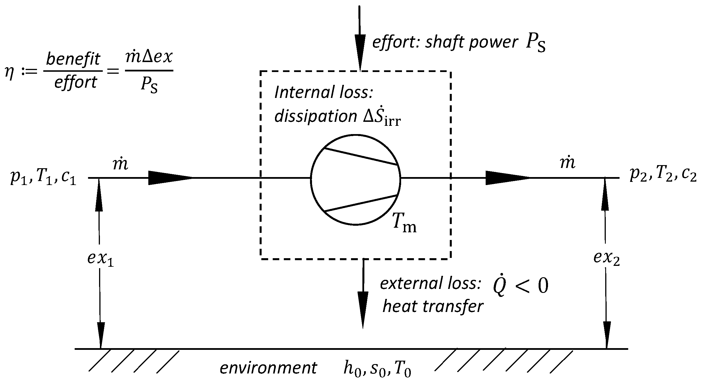
The function of a fan or compressor is to increase the exergy of the delivered gas. The exergy measures the working capacity of the gas relative to its environment. The mass-specific exergy of a fluid particle before entering the turbomachine (see Figure 1) is defined as
When they pass though the fan, the exergy of the same fluid particles is increased to be
Hence, the benefit of the machine is given by the change in the flux of exergy
The benefit is the product of a “flux” and a difference in the potential . The effort to reach this benefit is the shaft power . It is the mechanical work that is performed on the fluid per unit of time.
Hence, the most natural definition of a machine’s efficiency, a fan or a compressor, is
For the consideration of the heat flow , we go back to the 1st and 2nd laws of thermodynamics (Equations (1) and (2)). We adhere to the usual norm, where is positive as long the heat flux is transferred into the machine. However, for turbomachines, the heat flux is, in most cases, travelling from the machine to the environment, i.e., . Hence, the temperature T in the second law of thermodynamics is the temperature of the source of the heat conduction. For , the pure temperature is the machine’s average temperature, which is larger than the ambient temperature .
Replacing the total enthalpy in the 1st law of thermodynamics by the exergy and by setting , the two axioms are written as
We are now in the position where the entropy difference can be eliminated from the two axioms:
This equation, based on axiomatic grounds, is most instructive ones when we are discussing efficiency. The first and second laws of thermodynamics now provide the clear interpretation of the exergetic efficiency:
Now, the internal and external losses mentioned above take shape as follows:
It is remarkable that it is not the entire heat flow that leads to losses, but it is only a share of it
This dimensionless ratio is known as the Carnotian efficiency. Moreover, it is well known that the fluid friction results in a dissipation rate , thereby reducing the efficiency. It is not well known that heat conduction reduces the efficiency, but only the “Carnot” part of that heat flux. With the abbreviations and , and the definitions (13) and (14), the important Equation (12) may be written in an equivalent form
Models for heat transfer and dissipation are necessary for the calculation. By using the equation for heat transfer for the outer loss, the loss can be represented as follows
with the heat transfer coefficient being α and the surface of the machine being A. The dissipative losses are machine dependent. This will not be discussed in detail in this paper, and so, reference is made to other work in the literature: Pelz et al. [14] give a detailed description of the losses for fans, and Schobeiri [15] gives one for compressors. In variant (i), a separate consideration of the heat transport losses and dissipative losses can be made, but this method is rather unsuitable for practical application due to the effort involved.
For a caloric and thermal ideal gas with specific a heat , , and , the entropy is measured by measuring the temperature and the pressure [16].
The absolute enthalpy is given by
Hence, is given by
With the specific work , the exergetic efficiency is given by
For an ideal gas, we hence have
Equation (22) shows two ways to calculate the exergetic efficiency:
(i) Calculation by specifying the losses;
(ii) Determination on calculating the generated entropy.
Variant (ii) is more suitable for the calculation of the exergetic efficiency since this can be determined solely by the inlet and outlet variables and the ambient conditions.
In comparison to the isentropic efficiency, (Equation (23)) is based on isentropic compression,
It is clear that the exergetic efficiency considers not only pure fluid power, but also the relation to the environment. The application of it to a fan highlights the distinctions.
3. Application to a High-Pressure Centrifugal Fan
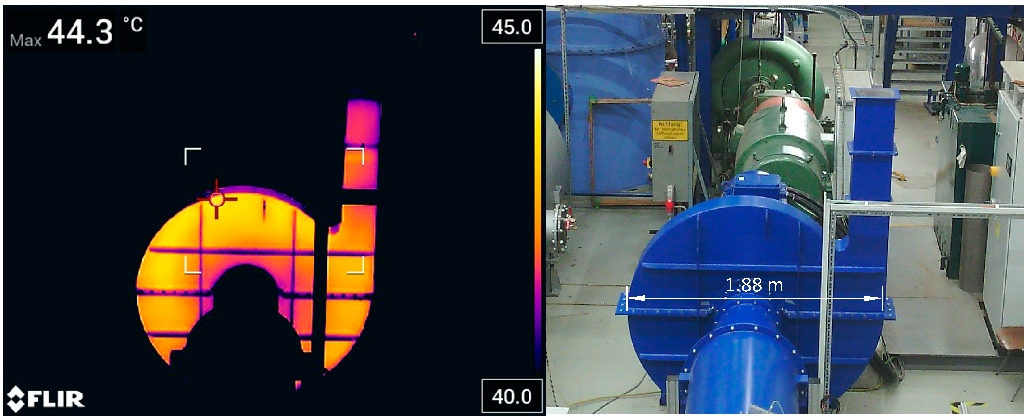
For the application of the exergetic efficiency, a high-pressure radial ventilator is chosen, as the differences are estimated to be more significant due to the higher temperature differences. The fan with an impeller diameter of is run with the rotational speed . The pressure build-up achievable with these conditions is a maximum of , and it is thus still within the scope of the ISO5801:2018 standard.
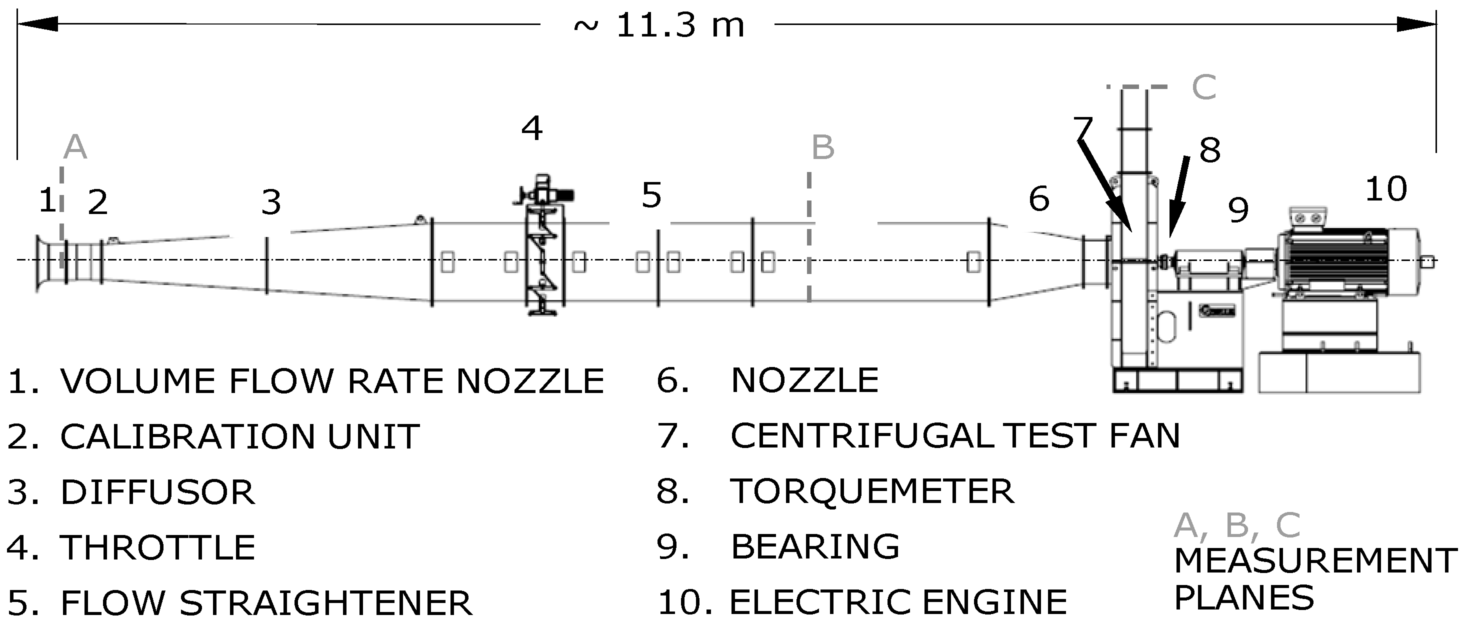
The setup of the centrifugal fan test rigs is shown in Figure 2 for the medium-scaled test rig. The flow goes from left to right and passes first through the volume flow rate nozzle (1, A). To improve the measurement accuracy, the volume flow nozzle has been calibrated with a total pressure comb (2). After the throttle (4), the flow straightener (5) is positioned to lower the turbulence and inhomogeneities. The fan inlet conditions (total temperature and static pressure) are measured in the measuring chamber at position (B). The test fan (7) is connected with a torque meter (8) to the engine (10). The torque meter is located between the impeller and the bearings. The fan blows out freely into the environment. At point (C), the static pressure can thus be assumed to be equal to the ambient pressure. Only the temperature is measured at the outlet. The ambient conditions are recorded in the experimental hall using a separate device.
Thermal images of the spiral housing were taken to quantify the machine temperature . An example is given in Figure 3, which shows the operating point of the maximum partial load. The determination of the heat flow requires the determination of the heat transfer coefficient α of the machine to the environment. The determination was complicated by the free-blowing fan. At maximum overload, mass flows of are conveyed, which corresponds to discharge velocities of . The exit flow leads to the circulation of the air in the area of the fan. The heat transfer coefficient is dependent on the flow around the machine, and thus, it was not constant in our experiments. By calculating the heat transfer coefficient backwards, based on the calculation of the heat flow by Equation (1), the coefficients could be compared with literature values, and thus, checked for plausibility.
The evaluation yielded heat transfer coefficients of for stagnant air for the partial load and for the full load, which corresponds to moderately to briskly moving air perpendicular to a metal wall according to the literature.
The example shows that calculating the exergetic efficiency on the basis of the resulting losses (Equation (12)) is impractical. Neither the dissipated work nor the heat flow can be easily determined. However, calculating the generated entropy based on the inlet and outlet conditions is possible and will be applied in the next section.
4. Comparison between Exergetic and Isentropic Efficiency
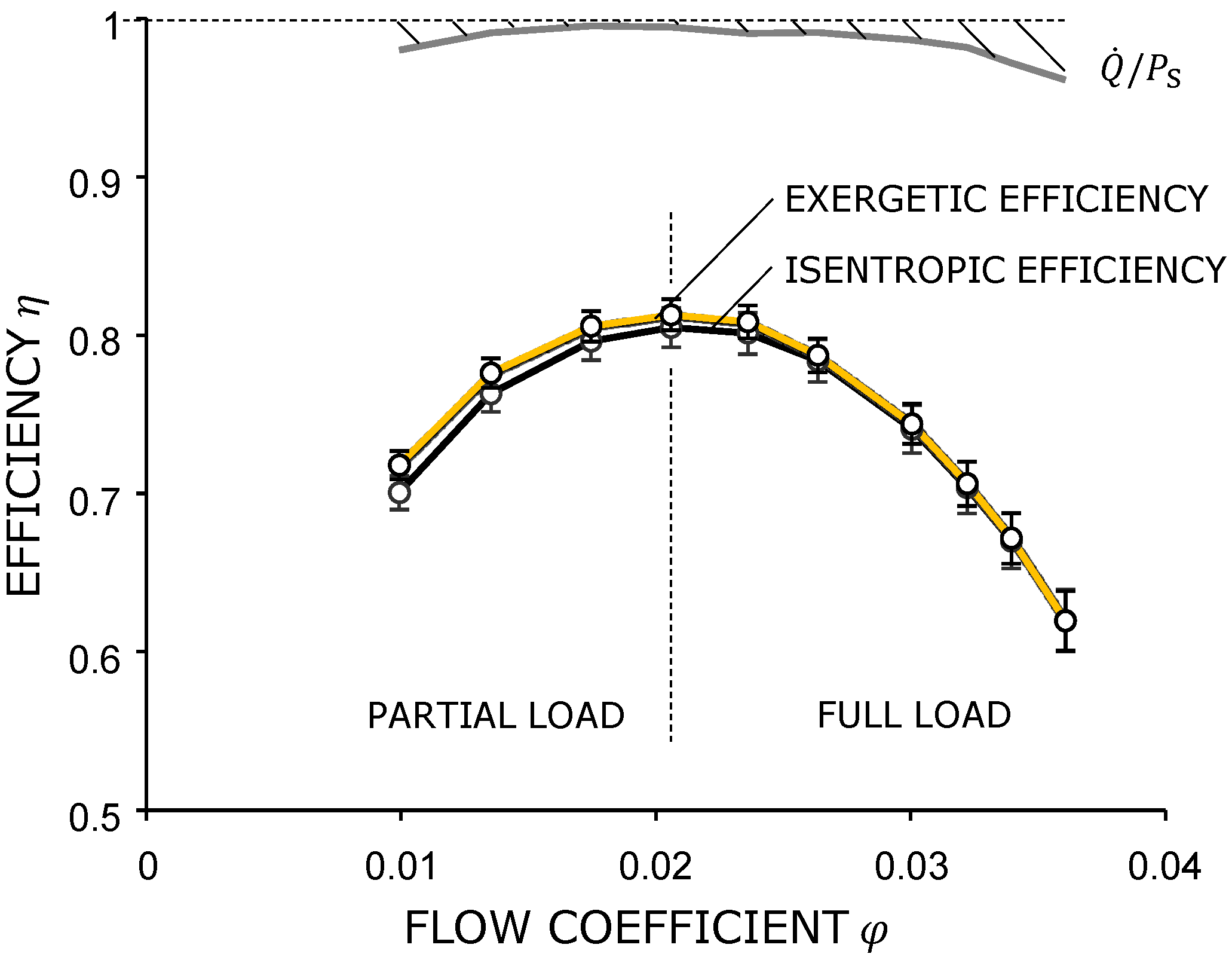
Figure 4 shows the comparison of the exergetic efficiency with the isentropic efficiency. For the isentropic efficiency, the power of the isentropic compression was set in relation to the impeller power, while for the exergetic efficiency, the calculation given in Equation (22) was used. The bars represent the uncertainty of the respective measuring points. For the calculation of each measuring point, a data set of 200 repetitions was measured, and the square of the uncertainty was derived from the sum of the squares of the statistical and systematic measurement uncertainty with a confidence interval of 95%. For the partial load, an uncertainty of about one percentage point can be seen, which increases to about two percentage points of the full load.
The differences in the overload operation between the two efficiencies are negligible. The efficiency difference increases during the partial load operation, with a maximum efficiency difference of 1.8 percentage points. This good correlation is remarkable despite the different calculation rules.
Where do the differences in efficiency come from? In the case of isentropic compression, a reversible change in state is assumed, which determines the integration path of the change in state. Since entropy is a state variable, the entropy difference does not depend on the choice of the integration path [17]. Accordingly, the exergetic efficiency is also independent of the choice of an integration path.
The exergetic efficiency includes not only the compression power, but also the reversible thermal power related to the environment. In the example that is shown, the difference between the outlet temperature and the ambient temperature is for the full load operation and for partial load operation. The usable thermal energy in relation to the environment is therefore low for the full load operation, while it makes the difference in efficiency for partial load operation. This thermal energy is caused by dissipation and is only usable from an exergetic point of view, but not from an energetic point of view.
In addition, Figure 4 shows the proportion of heat dissipation to the environment calculated using Equation (24) and verified using the thermal images. The dissipation has a minimum near the best efficiency point, and a maximum at the full load operation, with a share of about 4% points. In the partial load operation, the driving mechanism of heat transfer is heat conduction, while in the full load operation, increased heat convection is added. As the flow exits the fan into the experimental hall, the air circulates in the hall, and thus, also around the fan.
5. Conclusions
The first and second laws of thermodynamics are combined to achieve exergetic efficiency. As a result, its biggest benefit is, thus, its universal applicability. Exergetic efficiency does not only consider the fluid power from pressure build-up and delivery of a volume flow, but also the contained usable thermal energy in the environment.
The investigations show that a relevant difference between the isentropic and exergetic efficiencies becomes apparent in the partial load range with high pressure build-up. In the present application with a high-pressure centrifugal fan, an efficiency difference of 1.8% points between the exergetic and isentropic efficiencies could be found for the partial load operation.
If one considers the special case of the isothermal change in state, the exergetic efficiency almost becomes the isentropic efficiency, and only the difference of the logarithm of the pressure ratio remains. If one also assumes a pressure build-up that converges to zero, only the kinematic portion of the energy remains. This special case is found approximately in an axial fan without housing. The approximation of the mentioned limiting case can also be seen in the application example when one is looking at the full load operation.
A calculation of the exergetic efficiency based on the generated losses has proven to be impractical, but calculating the generated entropy based on the inlet and outlet conditions is possible and easy to implement. It has been shown that the exergetic efficiency can be determined with the test stands described in ISO 5801:2018.
The measurement effort increases especially when one is measuring the outlet temperature. Here, sensors with low systematic uncertainty are required in order not to worsen the overall uncertainty. The determination of the temperature of the flow also plays a relevant role for exergetic efficiency, which ought to be investigated more closely.
The thermal energy contained in the flow can be used to a certain extent. If the fan is used to ventilate buildings or tunnels, the surroundings will be heated with the thermal energy. Since fans are also used for cooling processes, such as in air conditioning systems, the exergy contained in the exhaust air flow cannot always be used, and it can even be counterproductive. The exergetic efficiency applied to fans must therefore always be considered in the system. Such system efficiency is becoming increasingly relevant today, as explained in the introduction. For the evaluation of the component, on the other hand, the isentropic efficiency is recommended, as it has a high acceptability among its users due to its simple applicability.
The investigation has shown that a relevant difference between the isentropic and exergetic efficiencies is to be expected, especially for machines with high-pressure build-up. Future useful applications will therefore be high-pressure fans, blowers and compressors, but also systems where there is a high temperature difference between the machine and the environment, e.g., a high-pressure fan in Antarctica. A further step in the investigation will be to compare diabatic and adiabatic machines.
Author Contributions
Conceptualization, J.B., C.S. and P.F.P.; validation, J.B.; writing—original draft preparation, J.B., C.S. and P.F.P. All authors have read and agreed to the published version of the manuscript.
Funding
This research received no external funding.
Institutional Review Board Statement
Not applicable.
Informed Consent Statement
Not applicable.
Data Availability Statement
Not applicable.
Conflicts of Interest
The authors declare no conflict of interest.
References
- de Almeida, A.T.; Ferreira, F.J.T.E.; Fong, J.; Fonseca, P. EUP Lot11 Motors: Final; University of Coimbra: Coimbra, Portugal, 2008. [Google Scholar]
- Arbeitsgemeinschaft Energiebilanzen e.V. Anwendungsbilanzen zur Energiebilanz Deutschland. 2023. Available online: https://ag-energiebilanzen.de/wp-content/uploads/2023/01/AGEB_21p2_V3_20221222.pdf (accessed on 5 September 2022).
- Betz, A. Wind-Energie und Ihre Ausbreitung Durch Windmühlen: Mit Zahlr. Tab; Aerodynam. Vers.-Anst: Göttingen, Germany, 1926. [Google Scholar]
- Pelz, P.F.; Metzler, M.; Schmitz, C.; Müller, T.M. Upper limit for tidal power with lateral bypass. J. Fluid Mech. 2020, 889, A32. [Google Scholar] [CrossRef]
- Carnot, S. Réflexions sur la Puissance Motrice du feu: Et sur les Machines Propres à Développer Cette Puissance; Bachelier: Paris, Italy, 1824. [Google Scholar]
- Fritzsche, A.F.; Hahnemann, H.W.; Rant, Z. Rundschau. Forsch. Im Ing. 1956, 22, 33–37. [Google Scholar] [CrossRef]
- Tsatsaronis, G. Definitions and nomenclature in exergy analysis and exergoeconomics. Energy 2007, 32, 249–253. [Google Scholar] [CrossRef]
- Sciubba, E.; Wall, G. A brief commented history of exergy from the beginnings to 2004. Int. J. Thermodyn. 2007, 10, 1–26. [Google Scholar]
- Massimo, M.; Federico, F.; Andrea, L. Proceedings of the ASME Turbo Expo: Turbomachinery Technical Conference and Exposition, Volume 8: Microturbines, Turbochargers and Small Turbomachines; Steam Turbines: On the Choice of Suitable Parameters for the Assessment of Industrial Fans Performance and Efficiency; American Society of Mechanical Engineers: New York, NY, USA, 2017. [Google Scholar]
- Nakhjiri, M.; Pelz, P.F.; Matyschok, B.; Horn, A.; Däubler, L. Apparent and Real Efficiency of Turbochargers under Influence of Heat Flow. In Proceedings of the 14th International Symposium on Transport Phenomena and Dynamics of Rotating Machinery, Honolulu, HI, USA, 27 February–2 March 2012, Verlag Nicht Ermittelbar, Honolulu, HI, USA; 2012. [Google Scholar]
- Dinçer, I.; Rosen, M. Exergy: Energy, Environment and Sustainable Development; Elsevier Science: Amsterdam, The Netherlands; Boston, MA, USA; Heidelberg, Germany; London, UK; New York, NY, USA; Oxford, UK; Paris, Italy, 2013. [Google Scholar]
- Sorguven, E.; Incir, S.; Highgate, J. Understanding loss generation mechanisms in a centrifugal pump using large eddy simulation. Int. J. Heat Fluid Flow 2022, 96, 108994. [Google Scholar] [CrossRef]
- Mazloum, Y.; Sayah, H.; Nemer, M. Exergy analysis and exergoeconomic optimization of a constant-pressure adiabatic compressed air energy storage system. J. Energy Storage 2017, 14, 192–202. [Google Scholar] [CrossRef]
- Pelz, P.F.; Saul, S.; Brötz, J. Efficiency Scaling—Influence of Reynolds and Mach Number on Fan Performance. J. Turbomach. 2021, 144, 061001. [Google Scholar] [CrossRef]
- Schobeiri, M.T. Turbomachinery Flow Physics and Dynamic Performance, 2nd ed.; Springer: Berlin, Germany, 2016. [Google Scholar]
- Gibbs, J.W. On the Equilibrium of Heterogeneous Substances; Universitätsbibliothek Heidelberg: Heidelberg, Germany, 1879. [Google Scholar]
- Baehr, H.D.; Kabelac, S. Thermodynamik: Grundlagen und Technische Anwendungen, 16th ed.; Springer: Berlin/Heidelberg, Germany, 2016. [Google Scholar]
Figure 1.
System boundaries of a turbomachine with inlet, outlet conditions and exchange with the environment.
Figure 1.
System boundaries of a turbomachine with inlet, outlet conditions and exchange with the environment.

Figure 2.
Pipe test rig according to ISO 5801:2018 with high-pressure centrifugal fan.

Figure 3.
Thermal images of the spiral housing. FST Lab., TU Darmstadt.

Figure 4.
Exergetic efficiency compared to isentropic efficiency. The calculated power loss due to heat dissipation to the environment is hatched.
Figure 4.
Exergetic efficiency compared to isentropic efficiency. The calculated power loss due to heat dissipation to the environment is hatched.

Disclaimer/Publisher’s Note: The statements, opinions and data contained in all publications are solely those of the individual author(s) and contributor(s) and not of MDPI and/or the editor(s). MDPI and/or the editor(s) disclaim responsibility for any injury to people or property resulting from any ideas, methods, instructions or products referred to in the content. |
© 2023 by the authors. Licensee MDPI, Basel, Switzerland. This article is an open access article distributed under the terms and conditions of the Creative Commons Attribution (CC BY-NC-ND) license (https://creativecommons.org/licenses/by-nc-nd/4.0/).
Share and Cite
MDPI and ACS Style
Brötz, J.; Schänzle, C.; Pelz, P.F. Exergy-Based Efficiency Assessment of Fans vs. Isentropic Efficiency. Int. J. Turbomach. Propuls. Power 2023, 8, 4. https://doi.org/10.3390/ijtpp8010004
AMA Style
Brötz J, Schänzle C, Pelz PF. Exergy-Based Efficiency Assessment of Fans vs. Isentropic Efficiency. International Journal of Turbomachinery, Propulsion and Power. 2023; 8(1):4. https://doi.org/10.3390/ijtpp8010004
Chicago/Turabian StyleBrötz, Johannes, Christian Schänzle, and Peter F. Pelz. 2023. "Exergy-Based Efficiency Assessment of Fans vs. Isentropic Efficiency" International Journal of Turbomachinery, Propulsion and Power 8, no. 1: 4. https://doi.org/10.3390/ijtpp8010004