Article

Investigations concerning the Flow Stabilization of Backward Curved Centrifugal Impellers at Low Flow Rate

1
ZIEHL-ABEGG SE, Ventilation Division, Heinz-Ziehl-Strasse, 74653 Künzelsau, Germany
2
Department of Mechanical Engineering, École de Technologie Supérieure, Université du Québec, 1100 rue Notre-Dame Ouest, Montréal, QC H3C 1K3, Canada
3
Department of Mechanical Engineering, Université de Sherbrooke, 2500 Boulevard de L’université, Sherbrooke, QC J1K 2R1, Canada
*
Author to whom correspondence should be addressed.
Int. J. Turbomach. Propuls. Power 2022, 7(4), 37; https://doi.org/10.3390/ijtpp7040037
Submission received: 22 August 2022 / Revised: 22 November 2022 / Accepted: 30 November 2022 / Published: 7 December 2022
(This article belongs to the Special Issue Fan Noise, Aerodynamics, Applications and Systems)

Abstract

:
For a backward curved centrifugal fan, reducing volume flow rate from design operating point towards part load yields an increase in noise emission together with a reduction of efficiency. The spectral content of the emerging noise emission can be characterized by a subharmonic hump with several harmonics. Based on narrow-band acoustic measurements and numerical Lattice-Boltzmann simulations, a deeper insight is sought after. Downstream unsteady flow patterns are identified to play a central role in this performance deterioration; and geometrical flow stabilization means are investigated.

Graphical Abstract

1. Introduction

It is a common observation for many fans that the noise emission increases significantly when moving on a characteristic curve starting from an optimal point with minimal noise emission towards lower volume flow rates at constant impeller rotation speed. Considering axial flow fans, Kameier and Neise [1] identified experimentally flow structures co-rotating with approximately half of the impeller rotation speed which they called “rotating instabilities”. They supposed the origin of that noise phenomena in a broader, but distinct frequency region below the blade passing frequency (BPF). Mongeau [2] describes characteristic noise sources for centrifugal turbomachines at 0.7, 1.5 and 2.1 times the BPF and relates it to a flow pattern rotating around 30% of the shaft speed. Rotating coherent flow structures as a source for narrowband noise in axial fans are described by Zhu at al. in [3]. A better understanding of these mechanisms and development of mitigation strategies could broaden the applicability of centrifugal fans towards lower volume flows and make them less sensitive to noise generation in this direction. In this paper, this kind of noise source is identified and characterized experimentally by considering a centrifugal backward-curved impeller with diameter D = 355 mm. The results are reproduced in a numerical setup with an unsteady Lattice-Boltzmann solver. Relying on the numerical results, a more profound insight into the noise generating mechanisms is generated. With this understanding, it was possible to construct and investigate modifications to improve the acoustic signature significantly. One mitigation technology is demonstrated both numerically and experimentally.

2. Experimental Investigation

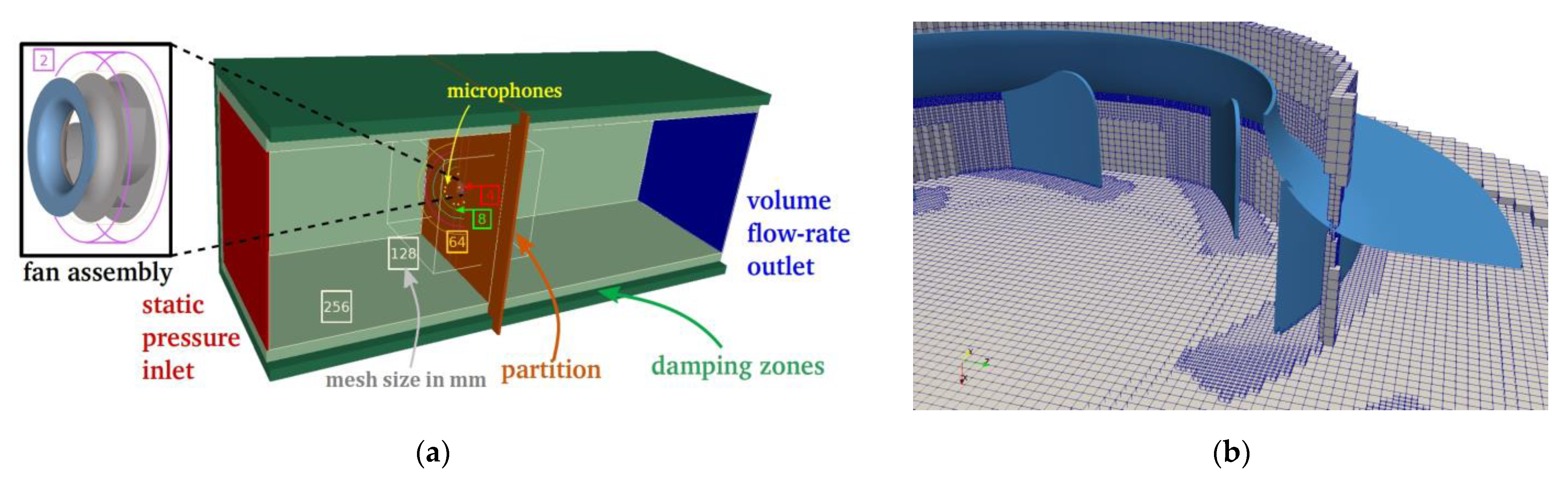
2.1. Configuration Description

The investigated centrifugal fan of diameter D = 355 mm shown in Figure 1a has seven backward curved blades made of sheet metal. The blades are circular profiles extruded perpendicularly to the flat hub. They are welded to the hub and to the curved rotating shroud. The fan is installed without housing. The ZIEHL-ABEGG anechoic facility shown in Figure 1b consists of two large anechoic rooms separated by a partition wall. A bell-mouth attached to the partition guides the flow into the fan installed in the downstream plenum (Figure 1a). The gap between the rotating shroud of the fan and the convergent intake is 3 mm. The fan is tested at constant rotational speed n = 2975 rpm for various flow rates, yielding a blade-passing frequency (BPF) of 347 Hz.

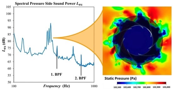
2.2. Experimental Results

Figure 2a shows the characteristic curves measured for the rotational speed n = 2975 rpm. The static pressure rise pfs as function of the volume flow rate QV is presented as a solid black line, and the sound power level LW6 measured in the pressure side plenum (downstream of the fan) as dashed black line. LW6 has a minimal value of 90 dB at QV ≈ 4000 m3/h Towards lower volume flow rates, the sound power level sharply increases up to 101 dB at QV ≈ 2000 m3/h. This kind of sound power surge in a region for low volume flows is typical of many fan designs. It is common for very different designs of backward curved centrifugal fans without housing. To investigate this behavior, the spectral content of LW6 is shown in Figure 2b for the three operation points highlighted with the vertical color lines in Figure 2a. At QV = 4440 m3/h, the spectrum is quite flat over the displayed frequency region from 100 Hz to 1000 Hz, except for some typical peaks at the blade passing frequency (BPF) and its harmonics. Moving towards lower volume flow rates, additional noise phenomenon is emerging in a large frequency range centered at approximately 80% of the BPF. The harmonics of this hump emerge as well but with a smaller amplitude. These phenomena are referred to as subharmonic humps. They are typical of (but not only) centrifugal and mixed-flow fans. Although the broadband noise grows towards lower volume flow rates as well, the mentioned steep growth of LW6 in Figure 2a can be strongly associated with this subharmonic. In the present work, a numerical investigation is performed to gain a deeper insight to the nature of the humps and the underlying sound generating mechanisms.

3. Numerical Investigation

3.1. Numerical Setup

The present simulations use the PowerFLOW solver 5.5a based on the Lattice Boltzmann Method (LBM). The approach is naturally transient and compressible providing a direct insight into hydrodynamic mechanisms responsible for the acoustic sources but also into acoustic propagation in the fan and outside in freefield. Instead of studying macroscopic fluid quantities, the LBM tracks the time and space evolution of a truncated particle distribution function on a lattice grid. The particle distribution evolution is driven to equilibrium by the so-called collision operator, approximated by the BGK (Bhatnagar–Gross–Krook) model [4]. The discrete Lattice-Boltzmann equations are solved with 19 discrete velocities for the third order truncation of the particle distribution function, which has been shown sufficient to recover the compressible Navier–Stokes equations for a perfect gas at low Mach number in isothermal conditions [5,6]. In PowerFLOW, a single relaxation time is used, which is related to the dimensionless laminar kinematic viscosity [6]. This relaxation time is replaced by an effective turbulent relaxation time that is derived from a systematic Renormalization Group procedure detailed in [7]. It captures the large structures in the anechoic room but also the small turbulent scales that develop along the blade and wall surfaces in a large eddy simulation manner. The particular extension developed for rotating machines can be found in Pérot et al. [8]. The computational domain includes the two coupled anechoic rooms, as shown in Figure 3a. The square cross section of the simulation volume has a width of 10 m, and the upstream and downstream plenums are also 30 m and 20 m long, respectively. The atmospheric pressure p = 101,325 Pa is imposed on the left red surface, while the volume flowrate Qv is imposed on the downstream red surface. The convergent inlet nozzle and detailed geometry of the fan impeller are considered. Only the motor and its shaft are discarded in the numerical setup. The mesh resolution in the domain is defined through successive embedded volumes, outlined in Figure 3, the mesh size being decreased by a factor of two between them. The resolution around the fan blades and the inlet nozzle wall is 0.5 mm, as shown on a fan cross section in Figure 3b. The volume around the fan is defined as a rotating volume at a rotational speed. Extended logarithmic wall functions to account for adverse and favorable pressure gradients [9] are applied on all wall surfaces. The total numerical domain counts 98 million cells and 7 million surface elements. Simulations are performed for several flow rates. First, the setup is initialized in two steps from pre-converged flow obtained from simulations with coarser meshes without the highest resolved refinement regions (50 revolutions computed on the mesh with maximum resolution of 2 mm and subsequently, 25 revolutions computed on the mesh with maximum resolution of 1 mm). Then, the final mesh described above (Figure 3b) is used for performance prediction. The convergence is obtained after two fan revolutions on the finest mesh, and data are acquired for further five fan revolutions. Static pressure is recorded at the exact locations of the microphones in the experiments. In addition, some cross-sections including the one at mid-blade height (midspan) and blade surface are recorded at high frequency sampling for frequency analysis. The numerical model presented above is validated through the comparison of performances with experimental measurements acquired on the certified ISO 5801 ZIEHL-ABEGG facilities.

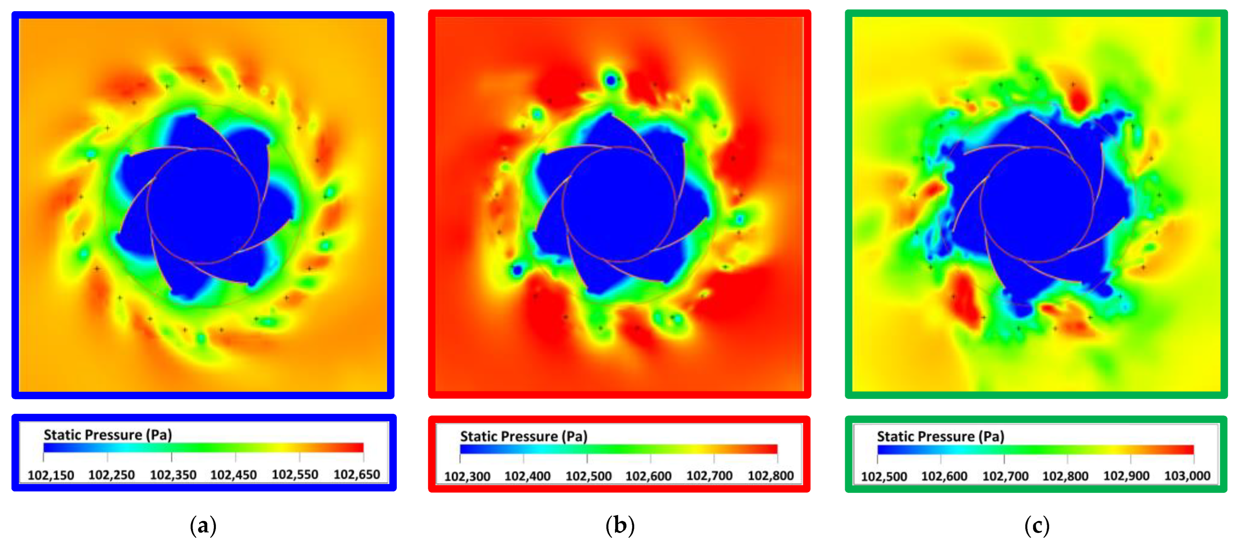
3.2. Numerical Results

The sound power levels LW6, computed in a similar manner as for experimental data in Figure 2b, are given in Figure 4b based on static pressure extracted from the LBM simulations. The main conclusion that can be drawn out of the comparison of the graphs of Figure 2b, replotted in Figure 4a, and Figure 4b is that the subharmonic humps are also the dominant noise mechanisms in the numerical method. The frequency resolution in Figure 4b is coarser than in Figure 2b due to the available sample length for the data of only about five impeller revolutions. Nevertheless, the emergence of the subharmonic humps of first and second order can clearly be observed in an equivalent way and a very similar quantitative extent as in the physical experiment. The intake distortion is the main cause of tones at BPF [10]. In addition, the inflow condition is more homogenous in the simulation than in the experiment (see for example [11]), as the flow field in the upstream plenum has not completely developed in the simulation due to the limited data acquisition period of only five impeller revolutions. Both limitations inherent in the simulations can explain the lower and wider peak at the BPF. Moreover, a first conclusion that can be drawn is that the mechanism of the generation of the subharmonic humps does basically depend on the downstream flow field generated by the impeller and corresponds therefore to a self-induced noise generating mechanism. By analyzing the unsteady flow field resulting from the LBM simulations carried out in the present model, one should be able to get some insight to this noise generation mechanism as it is well captured in the acoustic spectra.
In Figure 5, instantaneous pressure distributions at a blade mid-span cross-section are pointed out. Different flow structures downstream and radially outward of the impeller can be observed. These flow structures have different shapes (number of lobes) for each of the three flowrates. Decreasing QV, they get less symmetric, their circumferential wave numbers decrease, and they move radially inward towards the blades. It can be observed by use of unsteady visualization techniques that the flow structures correspond to vortical structures co-rotating with significantly reduced rotational speed compared with the impeller rotational speed. This is confirmed by a modal analysis in the next Section 3.3. The vortices are generated and supplied by detaching vorticity of the impeller blades, caused by flow separation phenomena at the blade suction side surfaces. It is assumed that the interaction of the impeller with the shown flow structures are the source of the subharmonic humps. The precise analysis of the noise generation mechanism inside the impeller induced by that interaction is content of future investigations. In the next section, an analysis is presented to characterize the rotating flow structures in a more tangible and quantifiable way in order to solidify the hypothesis that they are the original source of the subharmonic humps.

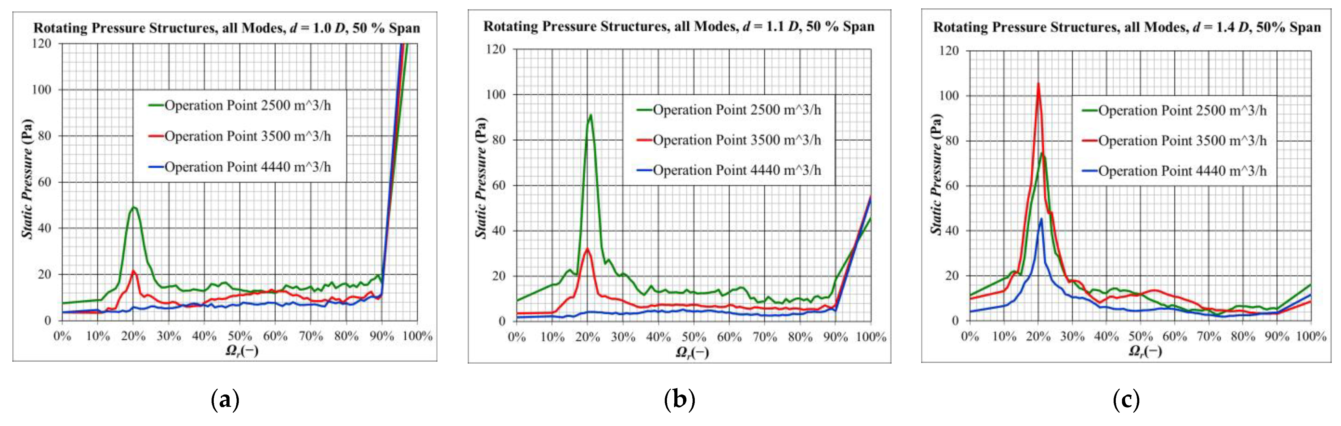
3.3. A Modal Analysis of the Flow Structures Based on Numerical Results

A somewhat intuitive analysis has been carried out to identify and characterize rotating flow structures with respect to their rotation speed and strength as function of operation point and radial and axial position. It was derived inspired by the method described in [12], with the aim to get additionally a quantitative evaluation of the amplitudes of the flow structures. In the analysis, an auxiliary “observer” grid consisting of co-axial circles with a discrete and equidistant discretization in circumferential (θ) direction is considered. This “observer” grid is rotated with arbitrary “test”-rotation speeds σi. At each instant, the unsteady flow data from a simulation is interpolated onto the “observer” grid. The flow field is then averaged in time. Note that an observer (grid) that would rotate at the same rotation speed as a spatial flow structure would observe this spatial structure as stationary. Thus, for this “synchronous” test rotation speed σi, after temporal averaging, the structures will still be present in the averaged fields. On the other hand, when the observer test rotation speed σi differs significantly from the flow structure’s rotational speed, structures will be smoothed out by the temporal averaging operator, assuming sufficiently long averaging time. So, the time-averaged flow data on each rotating observer grid represents spatial flow structures that rotate at the rotational speed σi. The described averaging has been carried out for a sufficiently high number of test rotation speeds σi. Some filtering technique has been applied in order to minimize the aliasing error in time associated with the interpolation from the cubic element grid from the simulation. The next step of the procedure consists of a circumferential Fourier transform for each test rotation speed σi in order to quantify periodic rotating modes. In Figure 6, some representative results of the analysis are presented.
The Relative Spin Ωr is defined as the ratio of test rotation speed σi and the impeller rotation speed: Ωr = σi/n. For each relative spin Ωr and flow quantity f of interest (for example, pressure or velocity), the time average over the five revolutions considered of the retarded function f ( x + Ω r · n · r · t ) is computed resulting in a spatial flow field f ˜ Ω r ( x ) = f ( x + Ω r · n · r · t ) with the time average operator · , which is subsequently analyzed by spatial Fourier analysis in circumferential direction at different axial and radial positions. The energy of all spatial pressure fluctuation modes of all wave numbers (the L2 norm of all Fourier coefficients unless the mean value as obtained by Fourier transform in circumferential direction) is shown in Figure 6 as function of Ωr. In Figure 6a, the rotating pressure fluctuation is given for a circle located at mid-span with a diameter d corresponding to the impeller outer diameter D, that is, probe locations are very close to the blade trailing edges. In Figure 6b the diameter d is 110% D; and in Figure 6c the circle diameter is 140% D. What can be observed is:
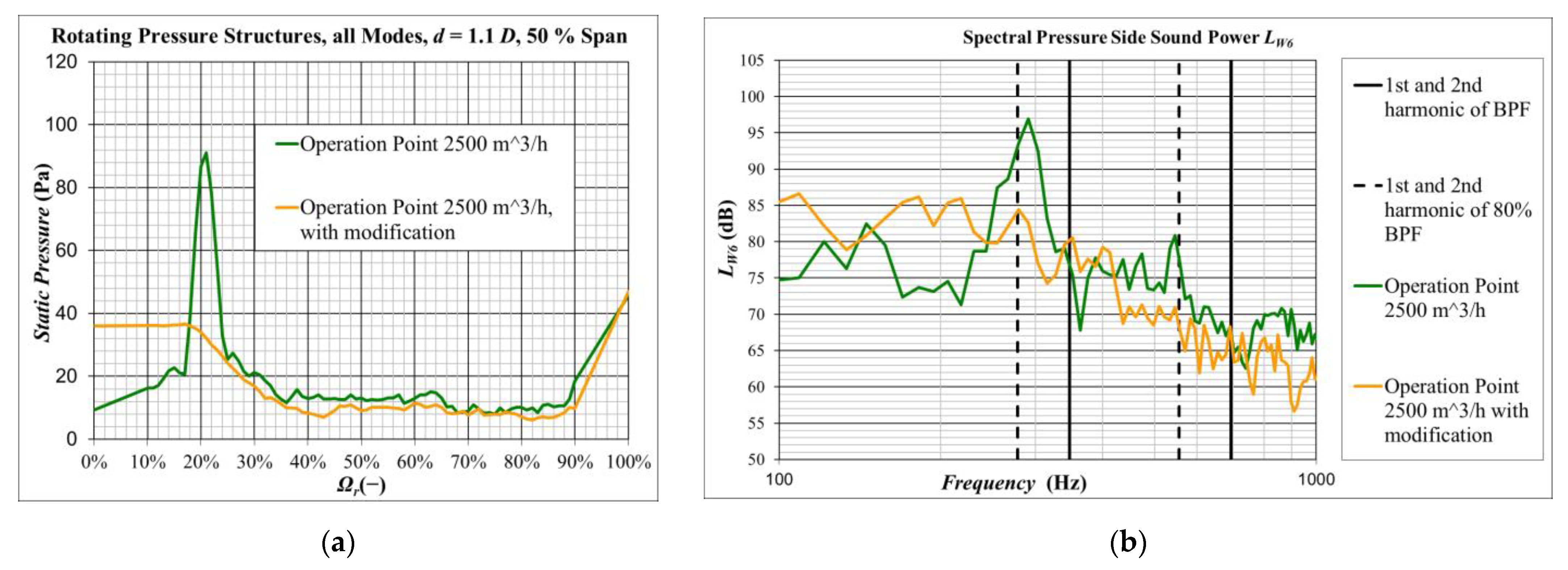
  • A 1st kind of distinct rotating structures can be observed at Ωr = 100 % (very right point in each graph). These are the expected co-rotating structures directly issued from the blades. Moving away from the blade, rotating structures at this Ωr decrease rapidly.
  • A 2nd kind of significative rotating structures can be observed, which has its maximum at Ωr ≈ 20 % (for the given particular impeller). Near the blade trailing edge at d = 1.0 D and d = 1.1 D ((a) and (b)), the amplitude of the fluctuation increases significantly with decreasing volume flow rate QV. The rotating structures have at a diameter of the blade trailing edge an important strength, especially for lower volume flow rates QV (Figure 6a, comparison of the three operation points).
  • The interaction frequency of a rotating flow structures is f0 = (1 − Ωr) · BPF. With Ωr = 20%, we get f0 = 80%∙BPF with consistency to what has been observed in Figure 2 and Figure 4.
  • Moving radially further from the blade trailing edges, the strength of the rotating fluctuations with Ωr = 20 % increases and dominates over the 1st kind of fluctuations that co-rotate with the impeller.
  • The rotating frequency of the fluctuations is not concentrated sharply at Ωr = 20 %, but has a significant dispersion, similarly to the broad shape of the subharmonic humps in the acoustic spectra.
  • At d = 1.4 D, the strength of the rotating structures for QV = 2500 m3/h already decreases, whilst the strength of the rotating structures for QV = 3500 m3/h still increases. The rotating structures come closer to the blade trailing edges when reducing the volume flow rate. This may be observed qualitatively also in Figure 4.

4. Fan Optimization

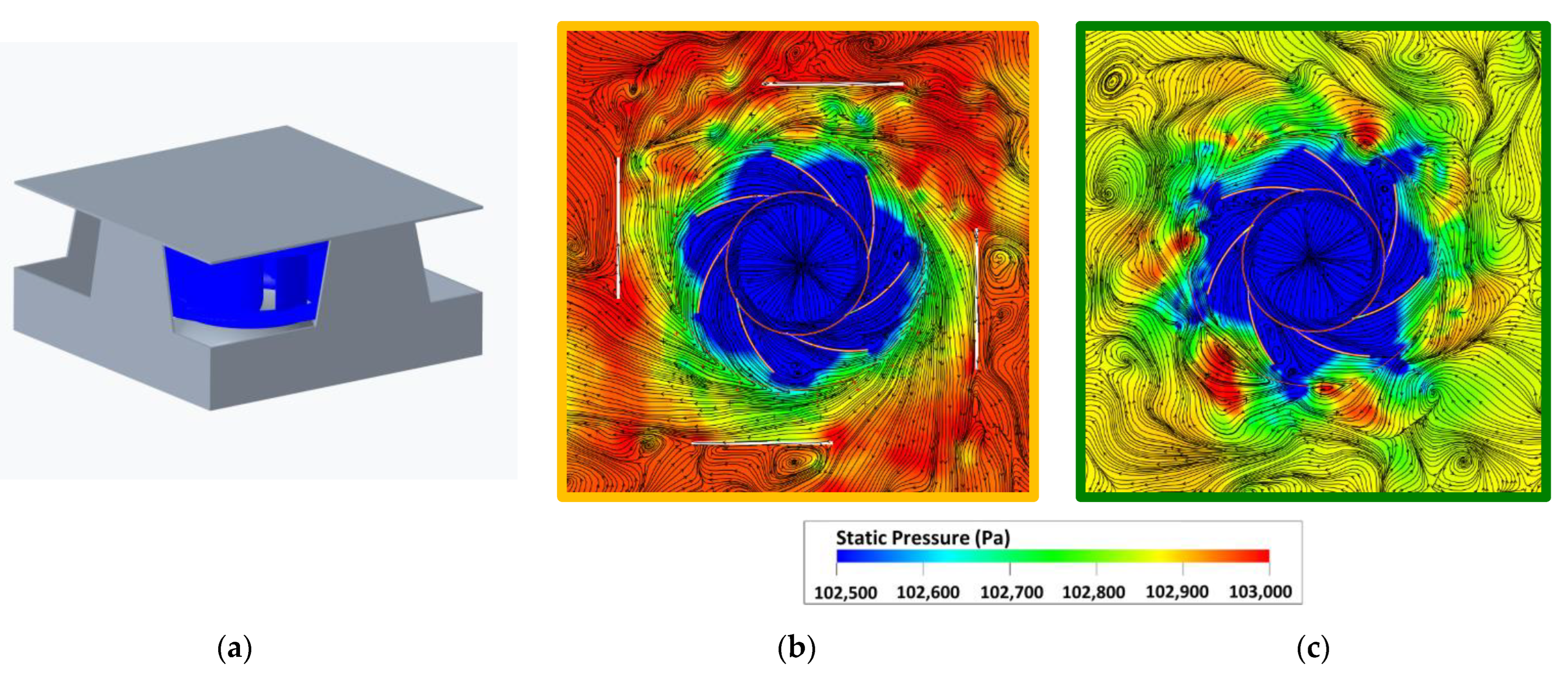
4.1. Numerical Investigations of Geometrical Modifications on the Downstream Side

Some geometrical modifications have been investigated with the objective to reduce the strength of the rotating flow structures with a relative rotational speed downstream in the vicinity of the blade trailing edges; or at least shift their appearance towards even lower volume flow rates. The investigated modifications consist of different vertical panels that result in convergent (or just moderately divergent) flow channels downstream the impeller. The result of one interesting modification is presented, whilst others showed effectiveness as well. The modified geometry leads to flow acceleration and stabilizes the flow downstream of the impeller. It may be seen as a simple kind of stator vane. Less rotating vortical structures build up or are washed further away from the blade trailing edges. This is clearly visible by comparing the flow picture on a plane midspan cut for the operation point QV = 2500 m3/h of Figure 7b, with modification, and Figure 7c, without modification. With the modification, significantly less vortical structures are present near the blade trailing edges, and more deterministic and better organized flow structures can be detected. This observation is supported by the modal analysis in Figure 8a. As presumed in the discussion of Figure 7, significantly less important rotating structures at Ωr = 20% are present with the modification. For Ωr = 0%, at the very left point of the graphs, representing the stationary spatial pressure fluctuations in circumferential direction, a clearly visible enhancement can be observed when using the modification due to the presence of a stator structure. The spectral content of the pressure side sound power LW6 is shown in Figure 8b. Clearly, the subharmonic humps are strongly reduced. As a side effect, the BPF harmonics are higher as spatial periodical stationary fluctuations are induced by the stator structure, interacting with the impeller blades.

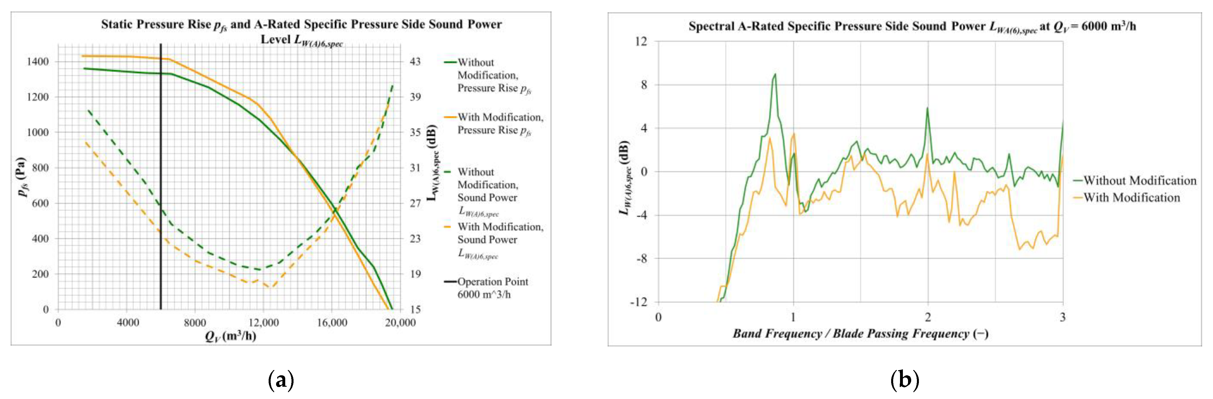
4.2. Experimental Data of an Implementation

Experimental results of the modification are shown. The geometry of the investigated pressure side optimization, which is similar to the structure investigated in the previous section and shown in Figure 7a, is depicted in Figure 9a, where it is installed on the test rig with an electrical drive. The comparison is based on measurements with a different impeller with five three dimensionally shaped blades. A wavy contour at the leading edges of the stator device has been applied in order to reduce the tonal noise resulting from rotor-stator interaction. Figure 9b shows a comparison of the characteristic curves of the measurements without and with the optimization device. Interestingly, the reachable pressure rise, and static efficiency are significantly enhanced. Similar to stator vanes, the added plates help in the pressure recovery from swirl.
In Figure 10, comparisons of the sound power levels are presented. At the left (a), the A-weighted sound power level LWA6 is shown as function of the volume flow rate QV. At the right (b), for the operation point at QV = 6000 m3/h, the spectral distribution of LWA6 can be seen. The frequencies are made dimensionless by the BPF. In Figure 10a it can be observed that the pressure side sound power is improved by the modification device at the left half of the duty curve, and the sound power reduction gets higher, up to 2 dB(A), for lower volume flow rates QV. In Figure 10b, it is clearly visible that subharmonic humps are present for this centrifugal fan both with and without modification device, especially at the first subharmonic order at about 80% of BPF. With the modification device, the humps are significantly reduced at the same volume flow rate confirming the observations obtained from the numerical investigations. The optimization is achieved by solely applying the downstream device, without modification of inflow conditions or anything in direct vicinity of the impeller, confirming the findings presented in this paper. The application of the pressure side optimization device, on the other hand, leads to an increase of tonal noise, especially at the first order, due to rotor–stator interaction, which is acceptable in the present case due to the relatively big distance (about 1.6 times of the impeller diameter) between impeller blade trailing edges and the wavy leading edges of the stator device. It is however interesting to consider that subharmonic noise is mitigated technically towards tonal noise at harmonics of the BPF, as due to the stator device, we get stationary flow structures rather than rotating flow structures interacting with the impeller blades.

5. Conclusions

Centrifugal fans without housing, amongst others, suffer from emerging subharmonic humps when decreasing volume flow rates. The sound power level increases drastically on the part load side from the optimal operation point. This is called a sound power surge. These are distinct regions in the spectra at harmonic multiples of 40–80% of the blade passing frequency (BPF), in particular the first harmonic that is largely dominating the sound power spectra. This noise phenomenon is associated with rotating flow structures downstream of the impeller, which interact with the trailing edge of the blades. For a specific fan, this was shown by using a numerical investigation using the Lattice Boltzmann method. A modal analysis has been performed on data collected downstream of the trailing edge. The dominant rotational speed of these flow structures is about 20% of the impeller rotation speed with the same rotation direction as the impeller. This result explains quantitatively the frequency regions (80% of BPF and multiples thereof, which is the basic interaction frequency between the impeller blades and the rotating structures) where the subharmonic humps occur. The rotating flow structures are self-induced by the impeller and supplied by detaching vorticity of the blade suction side surfaces. Two possible explanations can be given why the subharmonic humps grow with decreasing volume flow rate: Firstly, more vorticity is generated by the blades due to growing flow separations, and secondly, the vortices are washed away in a less effective manner due to the reduced volume flow rates. Several downstream modifications have been investigated in order to control the rotating flow structures. One example device was demonstrated both numerically and experimentally in this paper. The reduction of the rotating flow structures was proven by the numerical modal analysis model; and the resulting reduction of subharmonic noise generation was also shown by an experimental comparison. Interestingly, also the achievable pressure rises, and total-to-static efficiency is improved in regions of the duty curve, where subharmonic humps are reduced by the optimization device. This leads to the conclusion that the rotating flow structures have a negative impact on the swirl conversion into static pressure. The experimental results for the pressure side modification confirm the arguing derived from the numerical observations.

Author Contributions

Conceptualization, F.L.; methodology, F.L., S.H., M.S. and S.M.; software, S.H.; validation, F.L. and S.H.; writing—original draft preparation, F.L., S.H.; writing—review and editing, F.L., S.H., M.S., S.M.; visualization, S.H. All authors have read and agreed to the published version of the manuscript.

Funding

This research received no external funding.

Informed Consent Statement

Not applicable.

Data Availability Statement

Not applicable.

Conflicts of Interest

The authors declare no conflict of interest.

References

  1. Kameier, F.; Neise, W. Experimental Study of Tip Clearance Losses and Noise in Axial Turbomachines and Their Reduction. J. Turbomach. 1997, 119, 460–471. [Google Scholar] [CrossRef]
  2. Mongeau, L.; Thompson, D.E.; McLaughlin, D.K. Sound Generation by Rotating Stall in Centrifugal Turbomachines. J. Sound Vib. 1993, 163, 1–30. [Google Scholar] [CrossRef]
  3. Zhu, T.; Lallier-Daniels, D.; Sanjosé, M.; Moreau, S.; Carolus, T. Rotating coherent flow structures as a source for narrowband tip clearance noise from axial fans. J. Sound Vib. 2018, 417, 198–225. [Google Scholar] [CrossRef]
  4. Bhatnagar, P.L.; Gross, E.P.; Krook, M. A Model for Collision Processes in Gases. I. Small Amplitude Processes in Charged and Neutral One-Component Systems. Phys. Rev. 1954, 94, 511–525. [Google Scholar] [CrossRef]
  5. Chen, S.; Doolen, G.D. Lattice Boltzmann method for Fluid Flow. Annu. Rev. Fluid Mech. 1998, 30, 329–364. [Google Scholar] [CrossRef] [Green Version]
  6. Marié, S. Etude de la méthode Boltzmann sur Réseau pour les Simulations en Aéroacoustique. Ph.D. Thesis, Université Pierre et Marie Curie, Paris VI, Paris, France, 2008. [Google Scholar]
  7. Chen, H.; Filippova, O.; Hoch, J.; Molvig, K.; Shock, R.; Teixeira, C.; Zhang, R. Grid refinement in Lattice Boltzmann methods based on Volumetric Formulation. Phys. A Stat. Mech. Its Appl. 2006, 362, 158–167. [Google Scholar] [CrossRef]
  8. Pérot, F.; Kim, M.S.; Moreau, S.; Henner, M.; Neal, D. Direct Aeroacoustics Prediction of a Low Speed Axial Fan. In Proceedings of the 16th AIAA/CEAS Aeroacoustics Conference, Stockholm, Sweden, 7–9 June 2010. [Google Scholar]
  9. Fares, E. Unsteady flow simulation of the Ahmed ref. body using a Latt.-Boltz Approach. Comp. Fluids 2006, 35, 940–950. [Google Scholar] [CrossRef]
  10. Wolfram, D.; Carolus, T. Experimental and Numerical Investigation of the Unsteady Flow Field and Tone Generation in an Isolated Centrifugal Fan Impeller. J. Sound Vib. 2010, 329, 4380–4397. [Google Scholar] [CrossRef]
  11. Sturm, M.; Sanjosé, M.; Moreau, S.; Carolus, T. Aeroacoustic Simulation of an Axial Fan including the Full Test Rig by using the Lattice Boltzmann Method. In Proceedings of the Fan 2015 Conference, Lyon, France, 15–17 April 2015. [Google Scholar]
  12. Towne, A.; Schmidt, O.T.; Colonius, T. Spectral proper orthogonal decomposition and its relationship to dynamic mode decomposition and resolvent analysis. J. Fluid Mech. 2018, 847, 821–867. [Google Scholar] [CrossRef]
Figure 1. Experimental setup: (a) downstream view of the investigated fan; (b) anechoic test facilities at ZIEHL-ABEGG.
Ijtpp 07 00037 g001
Figure 2. Experimental results: (a) characteristic curve for static pressure rise pfs and sum pressure side sound power level LW6 at rotation speed n = 2975 rpm; (b) spectral content of pressure side sound power level LW6 for three operation points.
Ijtpp 07 00037 g002
Figure 3. Computational domain and refinement volume definitions: (a) numbers in squares provide the mesh size in mm for the outlined refinement volume; (b) and mesh resolution around the fan blades.
Ijtpp 07 00037 g003
Figure 4. Comparison of spectral results: (a) review of the experimental spectral results of Figure 2b; (b) numerical spectral results of the pressure side sound power level LW6 for the same three operation points (b).
Ijtpp 07 00037 g004
Figure 5. Instantaneous static pressure distributions at a plane cut in the middle between hub and rotating shroud (50% Span): (a) QV = 4440 m3/h; (b) QV = 3500 m3/h; (c) QV = 2500 m3/h.
Ijtpp 07 00037 g005
Figure 6. Results of modal analysis of the rotating structures downstream of the fan wheel at Midspan, for radial positions: (a) at d = 1.0 D; (b) at d = 1.1 D; (c) at d = 1.4 D.
Ijtpp 07 00037 g006
Figure 7. Results of the numerical investigation of a geometrical modification: (a) Sketch of the investigated geometrical modification; (b) instantaneous static pressure distributions with streamlines at a midspan plane cut for QV = 2500 m3/h with installed modification; (c) static pressure distributions without modification.
Ijtpp 07 00037 g007
Figure 8. Correlation of rotating structures and sound spectre: (a) modal analysis of rotating structures; (b) spectral content of Pressure Side Sound Power Level LW6.
Ijtpp 07 00037 g008
Figure 9. Experimental results for a fan with downstream modification: (a) photograph of implementation of a downstream modification on test rig; (b) and characteristic curves of static pressure rise pfs and total-to-static efficiency ηfs.
Ijtpp 07 00037 g009
Figure 10. Experimental evaluation of the impact of the downstream modification in A-weighted pressure side specific sound power LWA6 for the configuration of Figure 9: (a) sound power sum; (b) spectral distribution.
Ijtpp 07 00037 g010
Publisher’s Note: MDPI stays neutral with regard to jurisdictional claims in published maps and institutional affiliations.

