
Coulomb Spike Modelling of Ion Sputtering of Amorphous Water Ice

1
Université Paris-Saclay, CEA, Service de Recherche en Matériaux et Procédés Avancés, 91191 Gif-sur Yvette, France
2
Nuclear Science and Engineering Center, Japan Atomic Energy Agency (JAEA), Shirakata 2-4, Tokai, Ibaraki 319-1195, Japan
*
Author to whom correspondence should be addressed.
Quantum Beam Sci. 2023, 7(1), 7; https://doi.org/10.3390/qubs7010007
Submission received: 16 January 2023
/
Revised: 16 February 2023
/
Accepted: 23 February 2023
/
Published: 28 February 2023
(This article belongs to the Special Issue Quantum Beam Science: Feature Papers 2022)
Abstract
:The effects of electronic excitations on the ion sputtering of water ice are not well understood even though there is a clear dependence of the sputtering yield on the electronic stopping power of high-energy ions. Ion sputtering of amorphous water ice induced by electronic excitations is modelled by using the Coulomb explosion approach. The momentum transfer to ionized target atoms in the Coulomb field that is generated by swift ion irradiation is computed. Positively charged ions produced inside tracks are emitted from the surface whenever the kinetic energy gained in the repulsive electrical field is higher than the surface binding energy. For that, the energy loss of deep-lying ions to reach the surface is taken into account in the sputtering yield and emitted ion velocity distribution. Monte Carlo simulations are carried out by taking into account the interactions of primary ions and secondary electrons (δ-rays) with the amorphous water ice medium. A jet-like anisotropic ion emission is found in the perpendicular direction in the angular distribution of the sputtering yield for normal incidence of 1-MeV protons. This directional emission decreases with an increasing incidence angle and vanishes for grazing incidence, in agreement with experimental data on several oxides upon swift ion irradiation. The role of the target material’s properties in this process is discussed.
1. Introduction
The understanding of electronic excitation processes in solids is still a challenging issue, as regards, for instance, the radiation effects by fission fragments for nuclear applications, such as inert matrix fuels for actinide transmutation [1], or by cosmic rays for space applications, such as space travel [2,3] and satellites [4]. Among these, ion emission from surfaces induced by swift ions is an important issue [5]. Ion sputtering is known to be a very useful tool for various applications, such as thin film-controlled deposition [6] or nano-patterning of surfaces [7]. Besides, a more specific interest was also given to sputtering of water ice for astrophysics [8,9,10]. Two regimes of sputtering were found: the nuclear collision process dominates for low energy ions, below 10 keV, whereas the electronic excitation process dominates for higher energy ions [11]. The former regime is well described by Sigmund’s collisional model [8], whereas the latter one is not fully understood. The sputtering yield of water ice increases dramatically with the electronic stopping power in the latter case [12]. It deals with the transfer of electronic excitation to the kinetic energy of surface atoms which is a similar problem to ion track formation in solids. Two classical approaches were developed for tackling such problems: namely, the two-temperature model (TTM) or inelastic thermal spike (i-TS) model [13,14,15] and the Coulomb explosion model [16,17,18,19,20].
In the case of ionic-covalent solids such as crystalline LiF and UO2, huge sputtering yields were measured for swift heavy ion irradiations with a high electronic stopping power [21,22]. The broad isotropic angular distribution of the yield was interpreted on the basis of the i-TS model. However, this latter model could not account for the puzzling jet-like emission in the normal direction on top of this broad background. A similar directional sputtering was found for near-IR pulse laser sputtering of crystalline Al2O3 on time scales shorter than 1 ps [23].
Molecular dynamics (MD) simulations on the 150 fs time scale of amorphous solid Ar have also shown that such a directional sputtering could occur perpendicularly to the sample plane [24]. Other MD simulations of ion sputtering have also predicted atomic emission for time scales shorter than the Debye characteristic time (τD = ωD−1 ~1 ps) [18]. MD simulations of Coulomb explosion in silicon exposed to highly charged ions have shown that a shock wave is formed on a time scale shorter than 100 fs [18]. This is thought to occur when electrons are pumped out by the impinging ions from the surface by Coulomb interaction. In the case of ice, the H3O+ ion emission upon 100 keV Ar ion irradiation at 80 K was related to charging effects [25]. There is clear experimental evidence of space charge formation and dielectric breakdown in ice [25,26,27].
Ion sputtering was widely investigated for low and high energy heavy ions in a wide range of solids [5]. Typical cross-over behavior was found for ice from the nuclear collision regime for low energy ions and the electronic excitation regime for high energy ions [11]. A huge increase of the sputtering yield versus stopping power was found for the latter process in water ice [8,11,12] and other ionic-covalent materials such as LiF, CaF2, UO2, and Y3Fe5O12 [5,20,28]. Attempts were made to reproduce the variation of the total yield (Ytot) integrated over all emission angles versus electronic stopping power (Se) with the i-TS model for swift heavy ion irradiation [20,21]. The i-TS model was currently used to reproduce the variation of ion track radius versus Se for amorphizable as well as non-amorphizable solids [13]. A power law dependence of Ytot on Se was actually found for swift heavy ions with an exponent ranging between 2 and 4 for insulators [5,28], whereas a quadratic dependence was found for the lower energy ions [8]. The atomic collision process is well described by Sigmund’s collisional model, whereas the electronic excitation process is not convincingly modelled.
In the case of LiF, for instance, the binding energy of surface atoms deduced from the i-TS model applied to the dependence of Ytot on Se is much lower than the actual value by a factor of about two [21]. Moreover, the anisotropic jet-like emission for crystalline materials such as LiF and UO2 could not be modelled quantitatively. Note that this directional emission vanishes at high fluences for LiF in relation to the corrugation of the crystal surface [5]. However, this jet-like emission does not occur for amorphous silica (a-SiO2) [29]. The isotropic component for LiF is found to originate from the near-surface layer, whereas the jet component may be produced by deeper layers [28]. These authors claimed that this directional sputtering derives from a hydrodynamic effect on the pressurized vapor produced at high temperature in the tracks [21,22]. However, no quantitative model was given for this special feature.
Therefore, our aim was to investigate the relevance of a Coulomb spike effect on ion sputtering of amorphous water ice on very short time scales, by assuming a sustained electrical field induced by the ionizations inside ion tracks. It is a convenient way to test the likelihood of a Coulomb explosion in a solid to explain the sputtering yield. We show how ion sputtering with the jet-like emission can be explained by pure Coulomb field effects by using the RITRACKS computer code [2,3] devised for the liquid water medium that can be considered as a surrogate for amorphous water ice, as regards the ionization processes [30], electron pulse radiolysis [31], and the dielectric function [30,32]. In addition to ionization, electronic excitation, and dissociative electron attachment, RITRACKS considers vibrational and rotational excitations, which are characteristic of liquid water. Track structure calculations in ice require phonon excitation in place of the molecular excitations but, as discussed later, only ionizations are considered in this study; therefore, the differences of the excitation channels do not impact the applicability of RITRACKS. Hence, we have surmised that the sputtering of amorphous water ice can be modelled with the RITRACKS code. The impact of target material properties in this process is also discussed at length. This study can serve as a basis for addressing the ion sputtering of other dielectric materials such as oxides upon electronic excitations.
2. Method
We use the RITRACKS computer code [2,3] considering the liquid water medium at 0 °C. This Monte Carlo (MC) code can carry out the track-structure simulations of the primary ions on the basis of ionization cross section and excitation cross section of water. The secondary electrons produced by ionization reactions, the so-called δ-rays, and the valence electrons knocked out by these secondary electrons are also tracked considering reaction channels, namely, ionization, excitation, vibration–rotation, dissociative electron attachment, elastic collisions, and Bremsstrahlung until they reach 2 eV. The valence electrons knocked out by the electrons are also transported. The primary ions are transported until they reach the target surface defined as one of the setup parameters. On the other hand, electrons are tracked until they get thermalized. Unlike systematic fitting formulae [33,34], RITRACKS simulates all these reactions on an event-by-event basis by explicitly tracking every secondary electron and identifying the produced radiolytic species. Thus, RITRACKS can predict the spatial coordinates, timing, and transferred energy for each incident particle allowing the simulation of spatial and statistical fluctuation of the ionization reactions and excitation reactions. It should be noted that the RITRACKS always assumes that the target is liquid water. The cross sections and radiolytic species production are calculated on this premise.
The basic setup of the calculation performed by RITRACKS was a primary proton with kinetic energy of 1 MeV directed to a 500 nm-thick and infinite-wide water slab target. Every time the primary proton knocks out an electron from a water molecule, its spatial coordinate was dumped to an external file as a point of ionization. This feature was used by activating the “events” option of RITRACKS. Since the range of 1-MeV proton is much longer than 500 nm, it is reasonable to assume that the proton energy is constant. Calculation is conducted for 104 histories by using different random number seeds to achieve good statistical accuracy better than 10 %, except for insignificant minor events. This statistical accuracy is justified by the fact that the angular distributions of the ejected ions, the main scope of this paper presented later, have fluctuations in the order of 10%, which is small enough to analyze the distribution trends. The spatial coordinates of ionizations directly induced by the incident particle are the output at the end of all the histories and are used to calculate the electric potential between the resulted ions. We have considered that the produced ions are H3O+ [25]. The kinetic energies of ions which are driven by the potential are calculated. The kinetic energy (Ec) owing to 500 neighboring positively charged ionized atoms is computed based on the spatial coordinates of ionizations. The direction of the ions’ motion is calculated on the basis of the electric field exerted by the most neighboring ions. This calculation is justified by the fact that the electric potential is inversely proportional to the distance between charges while the electric force, which determines the direction of the kinetic motion, is inversely proportional to the square of the distance. Calculations for 2000 and 4000 neighboring ionized atoms show that the electric potential attributed to the ionized atoms beyond the 500th neighbor is negligible. Ionized atoms in the ion track are emitted from the surface if Ec ≥ Eb, where Eb is the surface binding energy. A low value of Eb = 450 meV was selected, as recommended by the literature for water ice [8]. Since no value is available for H3O+ ions, the binding energy of water molecules is used. However, the dependence of Eb on the direction of emission is not taken into account in the present simulations because the kinetic energy of the emitted H3O+ ions is in the order of eV whereas Eb is in the range of meV.
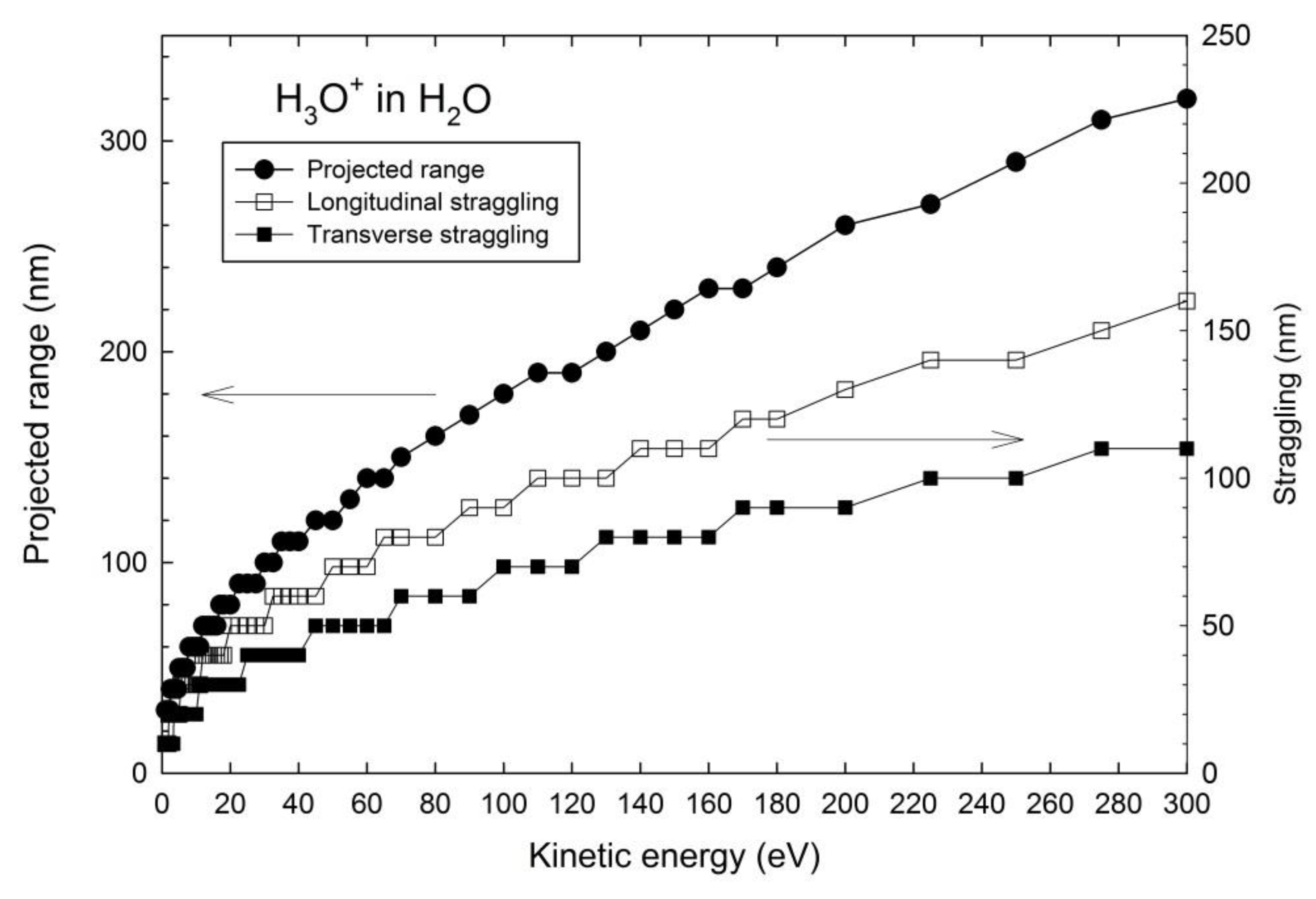
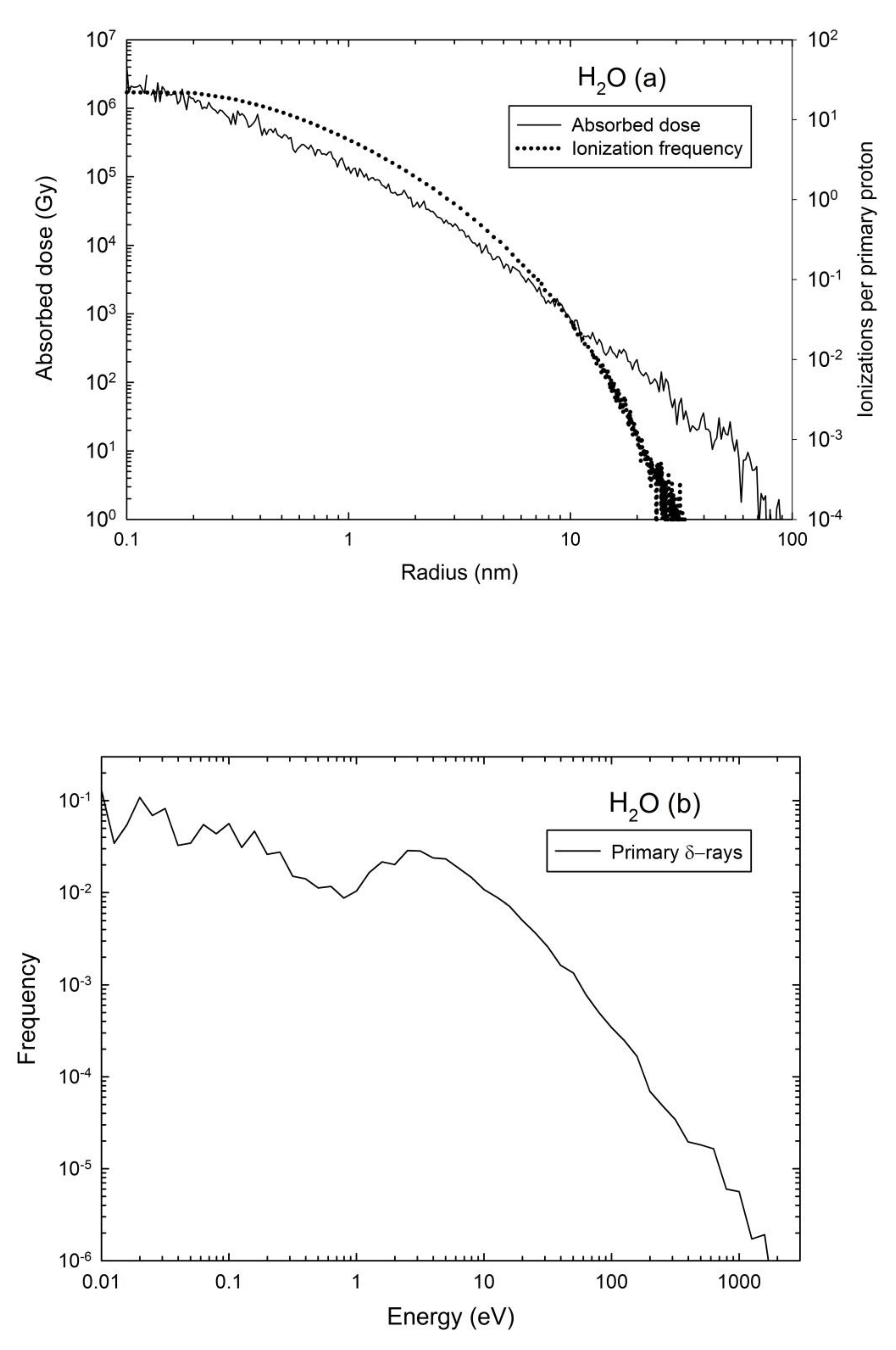
Contributions of deep layers are included with corrections to Ec due to the energy loss (ΔE) of H3O+ ions to escape from the depth to the target surface, as computed with the SRIM2013 MC codes [35]. SRIM2013 cannot calculate the range of H3O+ ions so the stopping power of 19O was used instead. The calculations of projected range and range straggling of 19O+ ions are plotted as a function of the kinetic energy below 100 eV (Figure 1, which are calculated by fitting based on LSS theory [36,37]. The calculation by SRIM of the nuclear stopping power, which is dominant at low energies, is more accurate than that by the LSS theory [38]. We assumed that those ions are one of the main emitted charged species for high-energy projectiles [8,9,25,39]. The possible emission of neutral species is of course not addressed by the present model based on Coulomb interactions. Multiple ionizations in tracks may reduce the yield of H3O+ ions for heavy ions with a higher stopping power [40] which are not taken into account in the present case for the lower density of ionizations produced by protons in tracks. Benchmark of RITRACKS code is performed against the radial distribution of deposited energy by ionization and electronic excitation for 1-MeV protons (p+) in water and number of ionizations per primary proton (Figure 2a) with reference to literature data [2,3]. The primary δ-ray spectrum is also computed (Figure 2b).
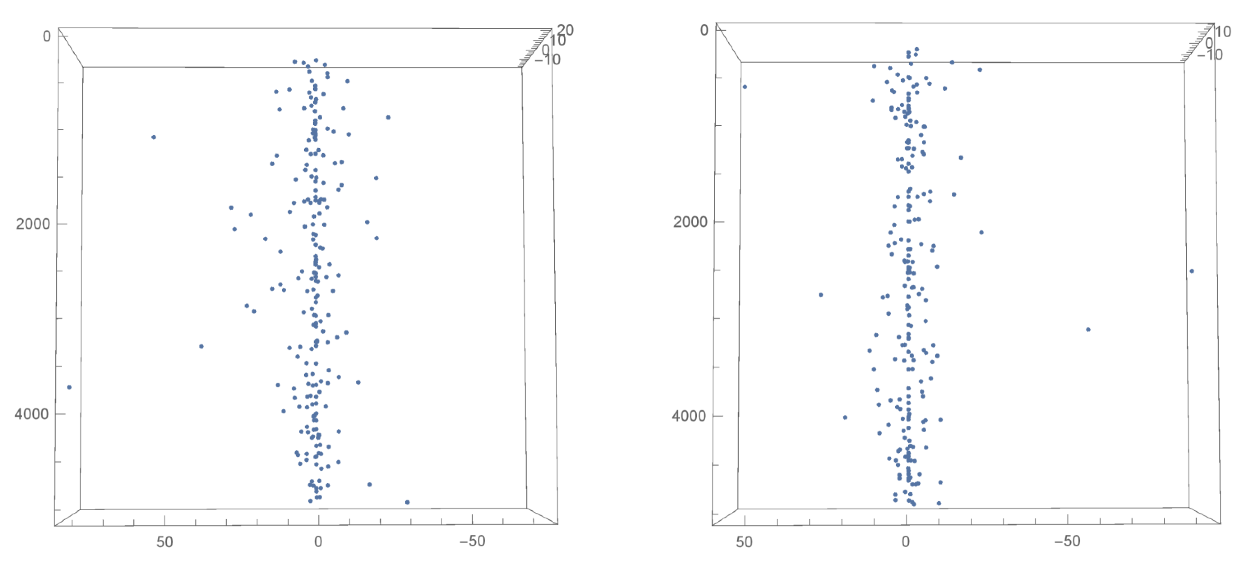
Calculations of the radial distribution of ionizations (Figure 2a) and spectrum of emitted ions are actually carried out from forces exerted on ions under impact of 1-MeV p+, with the computed radial energy deposition profile (Figure 2a). Typical 3D snapshots of ionization tracks are shown (Figure 3). Spatial distributions of ionizations are displayed for three randomly selected proton impact events. The time evolutions of the real (ε’) and imaginary (ε’’) parts of the dielectric constant show that the electric field is relaxed after ~100 fs [41,42]. Within 100 fs, a kinetic energy up to 20 eV is imparted to H3O+ ions which move less than 6.2 nm during this time step. The time step of Δt = 100 fs is large enough to calculate the kinetic energy based on the electric potential without consideration for time-dependent kinematics. The real part of the dielectric constant (ε’) is taken for calculating the electrostatic potential and electrical forces exerted on the ionized atoms for such a short time scale. The total yields (Ytot) of produced and emitted H3O+ ions are computed as a function of depth. The sputtering yield (Y) is also computed as a function of the emission angle (θ) for variable incidence angle (α).
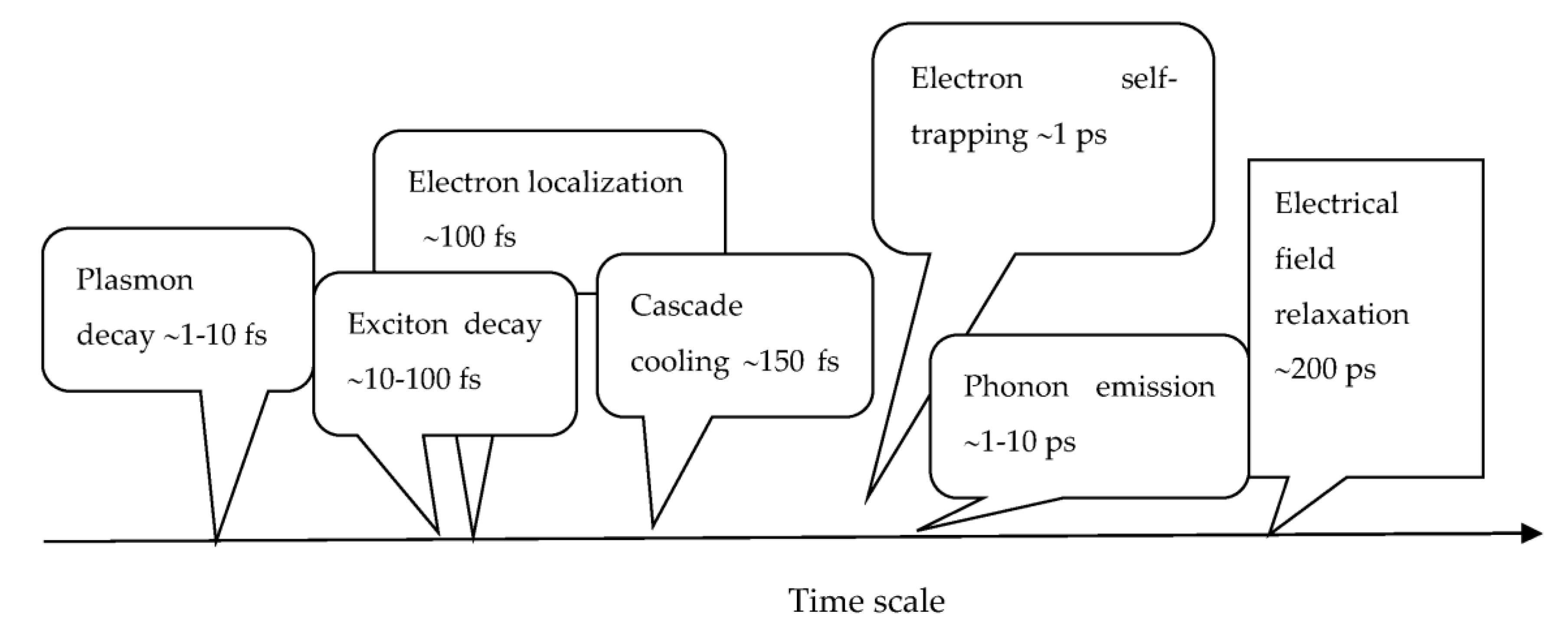
The time scales are summarized as below in Figure 4. The plasmon decay time is ~1–10 fs and exciton recombination time is ~10–100 fs. The cooling time of electronic cascade down to 1-keV kinetic energy is ~10–100 fs, and the cooling time from 1 keV to thermal energy is ~40 fs. The ion penetration takes place in ~100 fs, which is the end of electronic cascade and the time t = 0 for our calculations. The electrical field relaxation is achieved for ~200 ps, whereas the Debye relaxation time is ~1 ps and phonon emission time is ~1–10 ps.
This time scale shows that the total cooling time of the electron cascade (~150 fs) to the cutoff energy of 2 eV is longer than the time step used in the simulations, Δt = 100 fs. Moreover, the range of δ-rays is larger than the track radius of ~10 nm (Figure 2a) in our simulations. This means that the electron gas is not thermalized at this stage and spread away from the track core during Δt. Simulations of ionization cascades in both liquid water and amorphous water ice actually found that the number of secondary electrons increases as a function of time up to a saturation in ~100 fs with only small differences between the liquid and solid phase [30]. A backward motion of the thermalized electrons to the track core might take place on a longer time scale because they are strongly trapped, as discussed below.
The mobility of the solvated electron (eaq−) in amorphous water ice can be considered as very low due to self-trapping into polaronic states on polar H2O molecule clusters [43]. Two-photon pump probe laser excitation of water ice has shown that electron localization occurs in ~100 fs and self-trapping in ~1 ps [44]. Calculation of the electron transport in liquid water was computed by a time-dependent MC method [45]. The temporal distribution of the spatial probability distribution of secondary electrons showed that electrons are trapped at the radial distance of 10 nm from the parent cations within 300 fs [45]. Trapping on localized levels in ice may even take place within a shorter time (~20 fs) for two-photon pulse laser excitation [46]. As a result, it is most unlikely that the ejected electrons would travel back to the track core from where they were kicked out during Δt. Therefore, the Coulomb field inside the track is not cancelled out on this time scale, and the produced H3O+ ions are not neutralized or shielded by the negative species which are sitting far away outside the tracks. The processes of neutral species production are not in the scope of this paper, as explained above.
Therefore, our assumption that the electric field remains unchanged until the ions are fully accelerated is justified. The H3O+ ions are accelerated in the timescale of 100 fs whereas it takes 100 fs–1 ps for the electric field to be relaxed owing to the trapping of electrons by the polarization of water molecules. RITRACKS can calculate transport of secondary electrons but owing to this time sequence, in which the secondary electrons are scarcely transported in the first 100 fs, the electrons were not taken into account to calculate the electric field and the consequent ion kinetic energy because they remain in the penumbra of the proton track.
Violation of the energy conservation is checked carefully. The deposited energy is distributed amongst four channels: (i) the emitted ions for Ec − ΔE ≥ Eb, (ii) the hot trapped ions in the target for Ec − ΔE < Eb, where Ec and Eb are the kinetic energy and binding energy of H3O+ ions, respectively, (iii) the energy deposited during the transport of ions (ΔE), and (iv) the δ-rays that have been ejected from atoms inside the target. This last channel of energy deposition is stored in the attractive Coulomb interaction of the δ-rays with the ionized atoms in the track. The spatial coordinates of the ionizations are randomly sampled based on the ionization cross sections; therefore, ions are occasionally produced within a small distance yielding an electric potential in the order of GeV. Apparently, such events violate the energy conservation law and they are disregarded. This corresponds to the mean distance between water molecules, i.e., 0.31 nm.
The energy stored in the ion path is the sum of those contributions. The second and third channels are released as thermal energy and phonon emission for Δt ≥ 1 ps. This will eventually induce a thermal spike effect for these longer time scales. As will be further seen in our results, the trapped ionized atoms in the second channel are produced with high kinetic energies.
3. Results
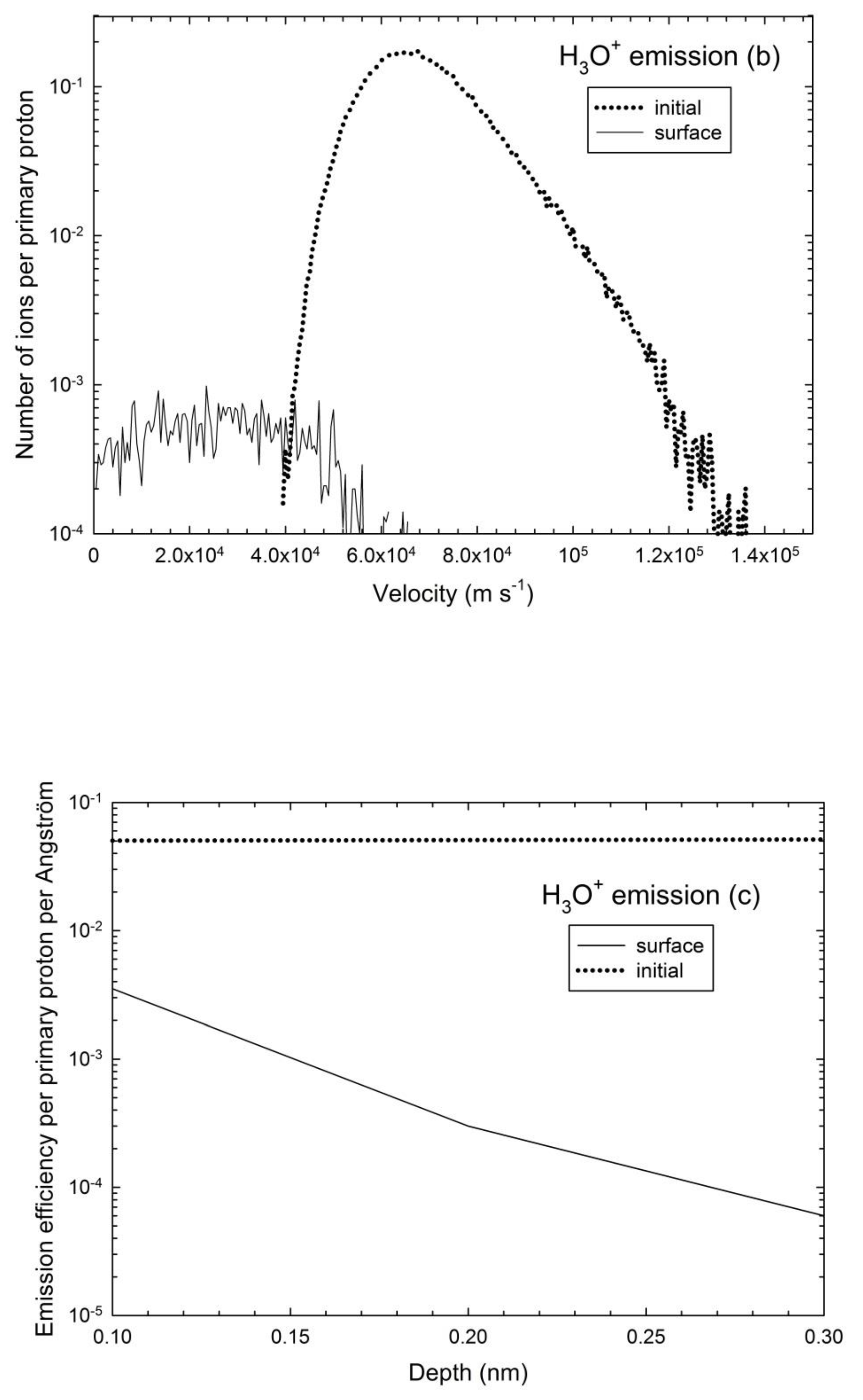
The kinetic energy and velocity spectra of sputtered H3O+ ions integrated over the whole target volume are plotted for α = 60° (Figure 5a,b). Broad in-depth (initial) and surface distributions of ions are observed as a function of Ec with a peak at low energy for the initial energy spectrum (dotted curve, Figure 5a). A clear downward shift of the energy and velocity distributions is seen from the initial distribution to the surface distribution due to slowing down of ions from the depth of target to the surface (Figure 5b). The related depth dependence of the emission efficiency or yield per incoming proton and per Å for α = 60° also exhibits a strong decay for the emitted ions whereas it is constant for the produced ions (initial depth distribution, dotted curve, Figure 5c). No ion emission occurs beyond a depth ~10 nm. The total yield of H3O+ ion emission deduced from Figure 5a is of Ytot = 0.149 (ion/primary proton). Given the high range of kinetic energies (Figure 5a), this emission yield is weakly depending on the selected value of Eb. Hence, the overall behavior of energy spectra and angular distribution will not be very much impacted by this value. Note that larger sputtering yields of ice at 10 K were measured for 95-MeV Xe ions, yet for a much higher stopping power of Se ~8 × 10³ keV µm−1 [47].
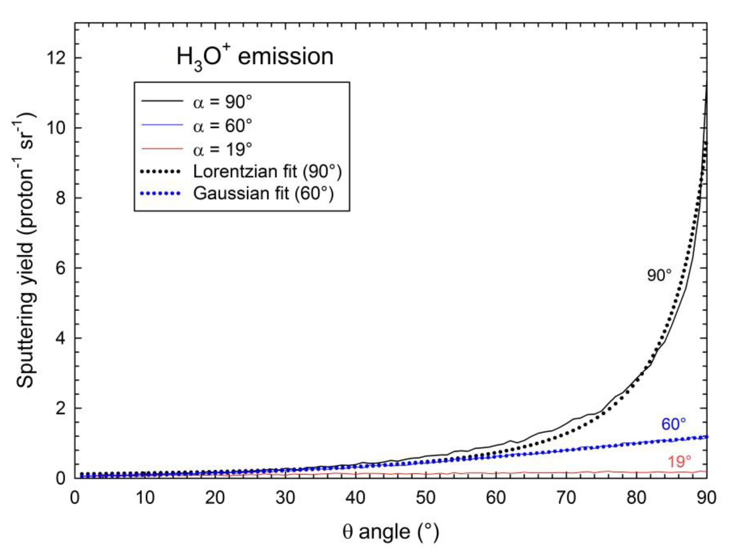
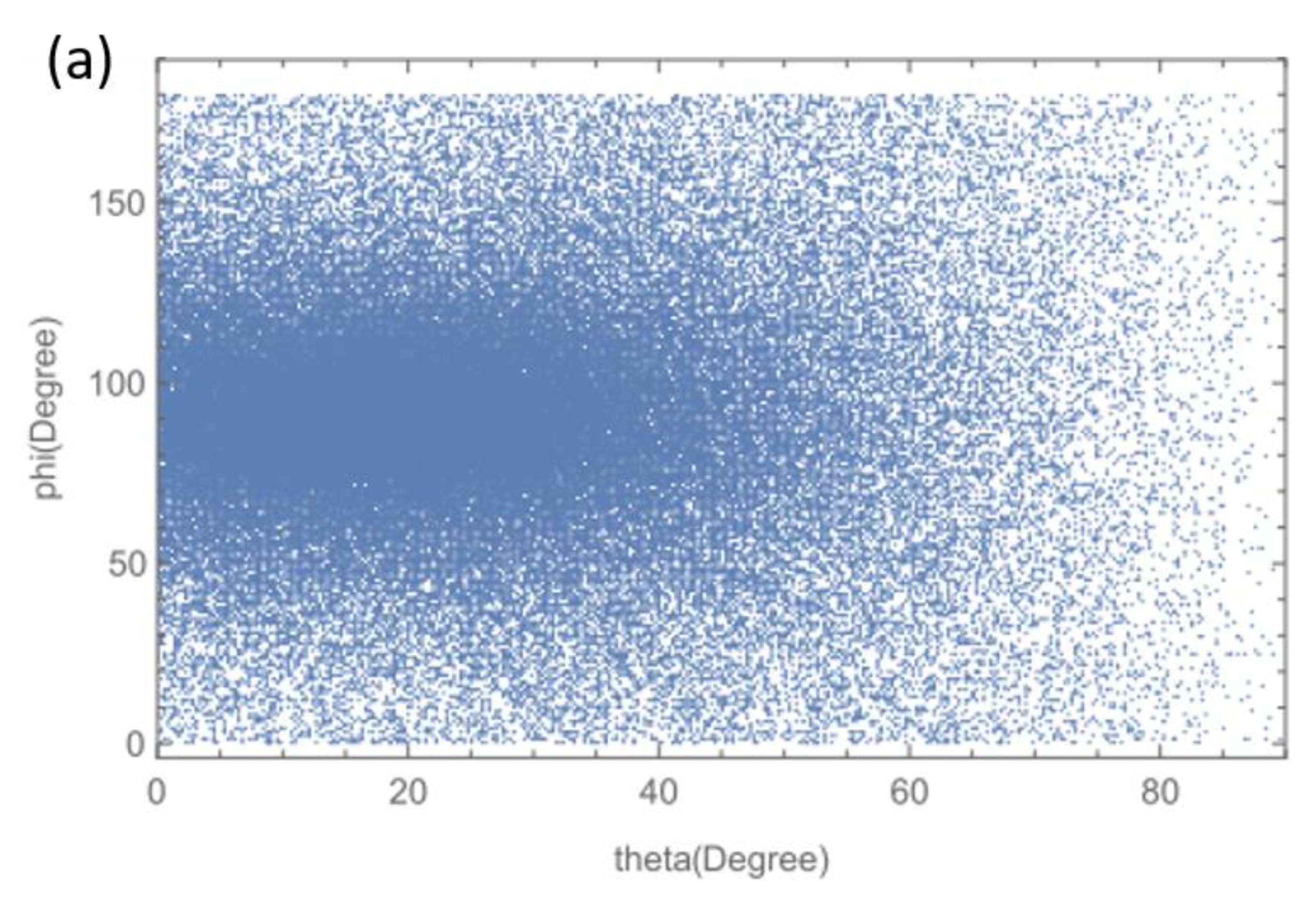
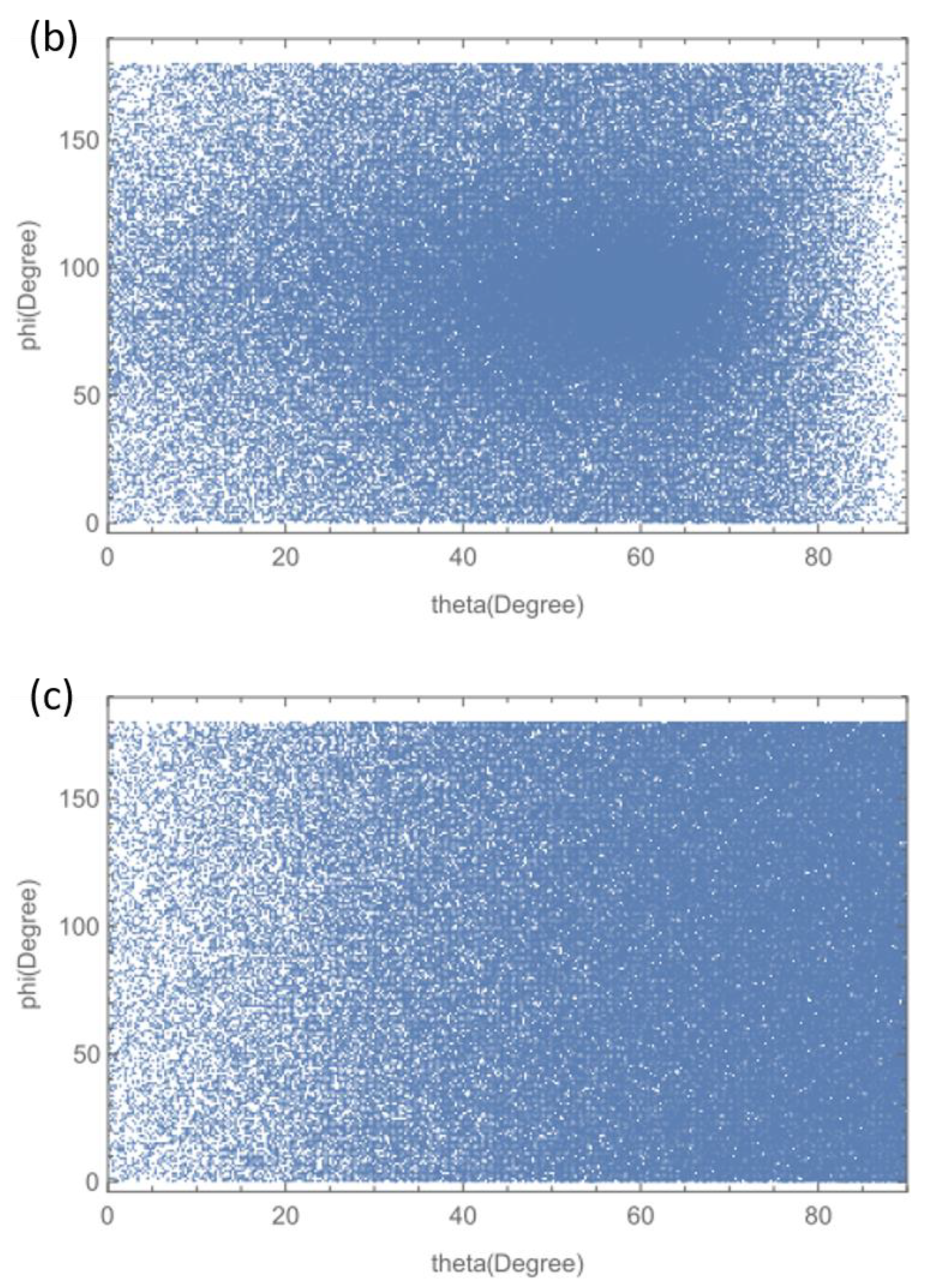
The angular distribution of yield shows a typical jet-like anisotropic emission in the normal direction (θ = 90°) for the normal incidence (α = 90°) (Figure 6). The plotted yields show the integrated yield over a polar angle variation Δθ corresponding to a ribbon detector with radius of 2 cm and width of 1 cm (Figure 7), like in experiments [21,22] Positive ions in the track are expelled perpendicularly to the target surface. The peak intensity decreases for decreasing α to 60° and is completely blurred out for near grazing incidence, i.e., α = 19° (Figure 6). A sharp Lorentzian profile is used for fitting the central part of this peak for α = 90°, and a Gaussian profile with a standard deviation of ~50° for α = 60°. Those fits are only meant to show the different shapes of the angular distributions. The width of these angular distributions is clearly larger than the angular straggling (≤15°) of emitted H3O+ ions (Figure 1b). The full θ–φ 2D angular distributions are displayed for α = 0°, α = 19°, and α = 60° (Figure 8a–c), where θ is the polar angle, α is the incident angle of the primary ion beam with respect to the target surface, and φ is the azimuthal angle in the target plane (defined in Figure 7). It is seen that the jet-like emission is only occurring for α = 90°. For the latter incidence value of 90°, a high density of blue dots is found near θ = 90°, corresponding to sputtered H3O+ ions collected on the ribbon detector (Figure 8c), whereas for α = 19°, the emission is directed toward θ = 0° in the target plane (Figure 8a). An intermediate behavior is found for α = 60°, in agreement with the angular distributions (Figure 6).
4. Discussion
4.1. Coulomb Spike Sputtering of Amorphous Water Ice
The present simulations show that ion sputtering induced by ionizations does occur during the time period in which the electric field is retained as explained above. During this short time step, a sufficient kinetic energy and momentum are transferred to the target ions to escape out from the surface. The kinetic energy spectra (Figure 5a) are in the same range as that of H3O+ ion emission with a sharp peak at ~35 eV, showing supra-thermal emission induced by 100-keV Ar ion irradiation at 45° incidence angle on an ice film of 420-nm thickness at 80 K [25]. Even though there is some contribution of sputtering induced by nuclear collisions in the latter case (~1 atom per incident ion, as computed with the SRIM2013 code), this cannot account for such a supra-thermal ion emission in the latter case.
The jet-like effect decreases for higher ion incidence angle (Figure 6), in agreement with experimental data on several insulating materials [5,21,22,28]. It is to be noted that, for such short time scales, neither thermally activated atomic motion can occur, nor any phase change such as melting or boiling, unlike for the i-TS model. No such assumptions are made since phonon emission/absorption processes are not required. Likewise, the major role of secondary electrons was shown for desorption of H2O molecules upon fs laser irradiation of liquid water, with a minor effect of phonons [48].
4.2. Role of Target Properties
Some challenging questions remain on the role of the material’s properties in this ion emission process. Actually, the jet-like anisotropic ion sputtering occurs for crystalline oxides, such as UO2, or LiF [21,22], which are not amorphizable, but not for an amorphous one, such as a-SiO2 [29]. However, this behavior also occurs for an amorphizable oxide such as Y3Fe5O12. The analysis based on a thermal effect is thus questionable for these refractory solids with similar high melting temperatures but showing quite different behaviors. The choice of Eb is indeed an important issue since it may govern the yield. However, this does not change drastically the overall behavior, except for the value of Ytot. Surface charge effects were put forward to account for the narrow jet-like emission for LiF [49] and UO2 [50].
The screening and/or neutralization of the positive ionic charge by the ejected secondary electrons are also important issues. As mentioned above, this is quite unlikely in the case of water ice owing to the strong trapping of ejected electrons on water molecule clusters [48], far outside the track cores. On the basis of X-ray emission spectroscopy data on a SiO2 aerogel irradiated with 11.4 MeV u−1 Ca ions, authors have claimed that core hole neutralization occurs on a time scale ~1 fs [51]. However, this strongly depends on the electron mobility which can be quite low in dielectric materials. This effect is certainly enhanced upon room temperature irradiations. Moreover, positive hole mobility is always very low in any case. The case of a-SiO2 is quite puzzling since fast neutralization was claimed by some authors on such a short time scale [51].
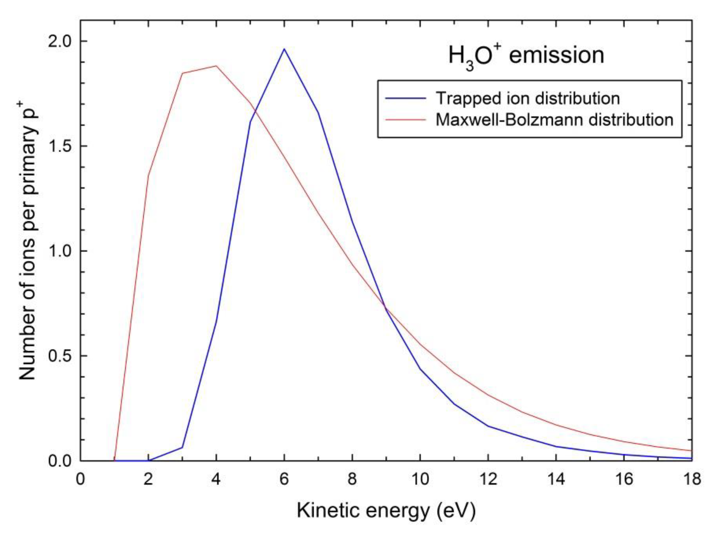
To summarize, based on simple approximations, the present simulations show that a directional ion sputtering with high-velocity ion emission from the surface can occur due to a Coulomb spike effect for very short time scales. No thermal and/or hydrodynamic effects are taking place at such short time scales. Thermal spike may occur for Δt > 1 ps and generate an isotropic sputtering background. Such a model can also serve as an input for the TS model by considering the ions with high kinetic energies trapped inside the target material. These ions will be subsequently thermalized for Δt > 1 ps and induce heating of the target material surface, as explained above in section II. The kinetic energy distribution of these ions corresponds to a temperature of 3 × 10⁴ K by using a Maxwell–Boltzmann statistical distribution (Figure 9). However, accurate fitting with such a kind of distribution is not feasible since these ions are not thermalized at this time step as for the pump-probe laser sputtering of Al2O3 [23]. Our model may be useful for understanding processes at longer time scales, such as hillock formation on surfaces of oxides after swift heavy ion-irradiation [52]. The extension of this study to the sputtering of ionic crystals induced by highly ionizing swift heavy ion irradiation is contemplated as a next step.
We are aware that our modelling, which is quite rough and simple, must be considered as preliminary. However, these MC simulations can serve as an input for a self-consistent MD simulation that calculates both the action of the Coulomb forces on the ions and the stopping of the ions by the neutral molecules in the frozen ice.
5. Conclusions
MC simulations of ion sputtering in amorphous water ice are carried out on the basis of the track-structure calculation by the RITRACKS computer code under 1-MeV protons for a time scale of 100 fs. Ionized atoms are emitted from a depth of ~10 nm to the target surface by taking into account the energy loss in the matter. A directional emission of positively charged H3O+ species is found in the angular distribution normal to the target surface for normal incidence of 1-MeV p+ due to the Coulomb field effect. This anisotropic jet-like emission is blurred out for oblique incidence of projectiles. Our calculation based on track-structure calculation suggests that the directional emission of charged species from irradiated materials is a result of the electric repulsion among the atoms ionized by the incident radiation. Moreover, our calculation showed that track-structure calculation, originally developed for radiobiology, is a unique and useful tool to understand the phenomena attributed to the electronic and molecular configurations in the material exposed to radiation.
One of the major limitations of the method used in this study is the target material. Owing to this limitation, the calculation was performed for liquid water. By using the generalized track-structure calculation code [53], the idea of this study can be applied to other materials and verified with greater variety of experimental data.
Author Contributions
J.-M.C.: conceived and designed the calculations, wrote the paper; T.O.: performed the calculations, contributed to writing the paper. All authors have read and agreed to the published version of the manuscript.
Funding
This research received no external funding.
Institutional Review Board Statement
Not applicable.
Informed Consent Statement
Not applicable.
Data Availability Statement
The data that support the findings of this study are available from the corresponding author upon reasonable request.
Acknowledgments
This work was supported by the Cross-cutting basic research program (RTA program) of the CEA energy division.
Conflicts of Interest
The authors declare no conflict of interest.
References
- Chauvin, N.; Konings, R.J.M.; Matzke, H.J. Optimisation of inert matrix fuel concepts for americium transmutation. J. Nucl. Mater. 1999, 274, 105. [Google Scholar] [CrossRef]
- Plante, I.; Cucinotta, F.A. Ionization and excitation cross sections for the interaction of HZE particles in liquid water and application to Monte Carlo simulation of radiation tracks. New J. Phys. 2008, 10, 125020. [Google Scholar] [CrossRef] [Green Version]
- Plante, I.; Cucinotta, F.A. Energy deposition and relative frequency of hits of cylindrical nanovolume in medium irradiated by ions: Monte Carlo simulation of tracks structure. Radiat. Environ. Biophys. 2010, 4, 5. [Google Scholar] [CrossRef] [PubMed]
- Velazco, R.; McMorrow, D.; Estela, J. (Eds.) Radiation Effects on Integrated Circuits and Systems for Space Applications; Springer: Berlin, Germany, 2019. [Google Scholar]
- Assmann, W.; Toulemonde, M.; Trautmann, C. Electronic Sputtering with Swift heavy Ions. In Sputtering by Particle Bombardment-Experiments and Computer Calculations from Threshold to MeV Energies; Behrisch, R., Eckstein, W., Eds.; Springer: Berlin, Germany, 2007. [Google Scholar]
- Cuomo, J.J.; Rossnagel, S.M.; Kaufman, H.R. (Eds.) Handbook of Ion Beam Processing Technology; OSTI: Albuquerque, NM, USA, 1989. [Google Scholar]
- Valbusa, U.; Boragno, C.; Buatier de Mongeot, F. Nanostructuring surfaces by ion sputtering. J. Phys. Condens. Matter 2002, 14, 8153. [Google Scholar] [CrossRef]
- Baragiola, R.A.; Vidal, R.A.; Svendsen, W.; Schou, J.; Shi, M.; Bahr, D.A.; Atteberry, C.L. Sputtering of water ice. Nucl. Instr. Meth. B 2003, 209, 294. [Google Scholar] [CrossRef]
- Baragiola, R.A.; Loeffler, M.J.; Raut, U.; Vidal, R.A.; Wilson, C.D. Laboratory studies of radiation effects in water ice in the outer solar system. Radiat. Phys. Chem. 2005, 72, 187. [Google Scholar] [CrossRef]
- Bringa, E.M.; Johnson, R.E. A new model for cosmic-ray ion erosion of volatiles from grains in the interstellar medium. Astrophys. J. 2004, 603, 159. [Google Scholar] [CrossRef]
- Fama, M.; Shi, J.; Baragiola, R.A. Sputtering of ice by low-energy ions. Surf. Sci. 2008, 602, 156. [Google Scholar] [CrossRef]
- Brown, W.L.; Lanzerotti, L.J.; Poate, J.M.; Augustyniak, W.M. "Sputtering" of Ice by MeV Light Ions. Phys. Rev. Lett. 1978, 40, 1027. [Google Scholar] [CrossRef]
- Dufour, C.; Toulemonde, M. Models for the description of track formation. Top. Appl. Phys. 2016, 61, 63. [Google Scholar]
- Nakajima, K.; Kitayama, T.; Hayashi, H.; Matsuda, M.; Sataka, M.; Tsujimoto, M.; Toulemonde, M.; Bouffard, S.; Kimura, K. Measurement of local temperature around the impact points of fast ions under grazing incidence. Nat. Sci. Rep. 2015, 5, 13363. [Google Scholar]
- Rymzhanov, R.A.; Gorunov, S.A.; Medvedev, N.; Volkov, A.E. Damage along swift heavy ion trajectory. Nucl. Instr. Meth. B 2019, 440, 25. [Google Scholar] [CrossRef]
- Fleischer, R.L.; Price, P.B.; Walker, R.M. Ion explosion spike mechanism for formation of charged-particle tracks in solids. J. Appl. Phys. 1965, 36, 3645. [Google Scholar] [CrossRef]
- Lesueur, D.; Dunlop, A. Damage creation via electronic excitations in metallic targets part II: A theoretical model. Radiat. Eff. Defects Solids 1993, 126, 163. [Google Scholar] [CrossRef]
- Cheng, H.P.; Gillaspy, J.D. Nanoscale modification of silicon surfaces via Coulomb explosion. Phys. Rev. 1997, 55, 2628. [Google Scholar] [CrossRef] [Green Version]
- Bringa, E.M.; Johnson, R.E. Coulomb explosion and thermal spikes. Phys. Rev. Lett. 2002, 88, 165501. [Google Scholar] [CrossRef] [Green Version]
- Szenes, G. Coulomb explosion at low and high ion velocities. Nucl. Instr. Meth. B 2013, 298, 76. [Google Scholar] [CrossRef]
- Toulemonde, M.; Assmann, W.; Trautmann, C.; Grüner, F. Jetlike component in sputtering of LiF induced by swift heavy ions. Phys. Rev. Lett. 2002, 88, 057602. [Google Scholar] [CrossRef]
- Toulemonde, M.; Assmann, W.; Muller, D.; Trautmann, C. Electronic sputtering of LiF, CaF2, LaF3 and UF4 with 197 MeV Au ions. Is the stoichiometry of atom emission preserved? Nucl. Instr. Meth. B 2017, 406, 501. [Google Scholar] [CrossRef]
- Stoian, R.; Ashkenazi, D.; Rosenfeld, A.; Wittmann, M.; Kelly, R.; Campbell, E.E.B. The dynamics of ion expulsion in ultrashort pulse laser sputtering of Al2O3. Nucl. Instr. Meth. B 2000, 166–167, 682. [Google Scholar] [CrossRef]
- Urbassek, H.M.; Kafeman, H.; Johnson, R.E. Atom ejection from a fast-ion track: A molecular-dynamics study. Phys. Rev. B 1994, 49, 786. [Google Scholar] [CrossRef] [PubMed]
- Baragiola, R.A.; Fama, M.; Loeffler, M.J.; Raut, U.; Shi, J. Radiation effects in ice: New results. Nucl. Instr. Meth. B 2008, 266, 3057. [Google Scholar] [CrossRef]
- Balog, R.; Cicman, P.; Field, D.; Feketeova, L.; Hoydalsvik, K.; Jones, N.C.; Field, T.A.; Ziesel, J.-P. Transmission and trapping of cold electrons in water ice. J. Phys. Chem. A 2011, 115, 6820. [Google Scholar] [CrossRef] [PubMed]
- Sagi, R.; Akerman, M.; Ramakrishnan, S.; Asscher, M. Temperature effect on transport, charging, and binding of low-energy electrons interacting with amorphous solid water films. J. Phys. Chem. C 2018, 122, 9985. [Google Scholar] [CrossRef]
- Assmann, W.; Ban-d’Etat, B.; Bender, M.; Boduch, P.; Grande, P.L.; Lebius, H.; Lelièvre, D.; Marmitt, G.G.; Rothard, H.; Seidl, T.; et al. Charge-state related effects in sputtering of LiF by swift heavy ions. Nucl. Instr. Meth. B 2017, 392, 94. [Google Scholar] [CrossRef]
- Toulemonde, M.; Assmann, W.; Trautmann, C. Electronic sputtering of vitreous SiO2: Experimental and modeling results. Nucl. Instr. Meth. B 2016, 379, 2. [Google Scholar] [CrossRef]
- Timmeanu, N.; Caleman, C.; Hajdu, J.; Van der Spoel, D. Auger electron cascades in water and ice. Chem. Phys. 2004, 299, 277. [Google Scholar] [CrossRef] [Green Version]
- Du, Y.; Price, E.; Bartels, D.M. Solvated electron spectrum in supercooled water and ice. Chem. Phys. Lett. 2007, 438, 234. [Google Scholar] [CrossRef]
- Lu, D.; Gygi, F.; Galli, G. Dielectric properties of ice and liquid water from first-principles calculations. Phys. Rev. Lett. 2008, 100, 147601. [Google Scholar] [CrossRef]
- Waligórski, M.P.R.; Hamm, R.N.; Katz, R. The radial distribution of dose around the path of a heavy ion in liquid water. Nucl. Tracks Radiat. Meas. 1986, 11, 309. [Google Scholar] [CrossRef] [Green Version]
- Sato, T.; Watanabe, R.; Niita, K. Development of a calculation method for estimating specific energy distribution in complex radiation fields. Radiat. Prot. Dosim. 2006, 122, 41. [Google Scholar] [CrossRef]
- Biersack, J.P.; Haggmark, L.G. A Monte Carlo computer program for the transport of energetic ions in amorphous targets. Nucl. Instr. Meth. 1980, 174, 257. Available online: www.srim.org (accessed on 1 January 2023). [CrossRef]
- Kabadayi, Ö.; Gümüs, H. Calculation of average projected range and range straggling of charged particles in solids. Radiat. Phys. Chem. 2001, 60, 25. [Google Scholar] [CrossRef]
- Bowyer, M.D.J.; Ashworth, D.G.; Oven, R.J. A revised version of the projected range algorithm with numerical solutions. Radiat. Eff. Defects Solids 1994, 130–131, 535. [Google Scholar] [CrossRef]
- Ziegler, J.F. The electronic and nuclear stopping of energetic ions. Appl. Phys. Lett. 1977, 31, 544. [Google Scholar] [CrossRef]
- Reeves, K.G.; Kai, Y. Electronic excitation dynamics in liquid water under proton irradiation. Nat. Sci. Rep. 2016, 7, 40379. [Google Scholar] [CrossRef] [Green Version]
- Gervais, B.; Beuve, M.; Olivera, G.H.; Galassi, M.E. Numerical simulation of multiple ionization and high LET effects in liquid water radiolysis. Radiat. Phys. Chem. 2006, 75, 493. [Google Scholar] [CrossRef]
- Yada, H.; Nagai, M.; Tanaka, K. Origin of the fast relaxation component of water and heavy water revealed by terahertz time-domain attenuated total reflection spectroscopy. Chem. Phys. Lett. 2008, 464, 166. [Google Scholar] [CrossRef]
- Tomita, H.; Kai, M.; Kusama, T.; Ito, A. Monte Carlo simulation of physicochemical processes of liquid water radiolysis: The effects of dissolved oxygen and OH scavenger. Radiat. Environ. Biophys. 1997, 36, 105. [Google Scholar] [CrossRef]
- Weiss, J. Primary processes in the action of ionizing radiations on water: Formation and reactivity of self-trapped electrons (’polarons’). Nature 1960, 4727, 751. [Google Scholar] [CrossRef]
- Bovensiepen, U.; Gahl, C.; Stähler, J.; Loukakos, P.A.; Wolf, M. Femtosecond dynamics of electron transfer, localization, and solvation processes at the ice—metal interface. Isr. J. Chem. 2005, 45, 171. [Google Scholar] [CrossRef]
- Kai, T.; Yokoya, A.; Ukai, M.; Fujii, K.; Toigawa, T.; Watanabe, R. A significant role of non-thermal equilibrated electrons in the formation of deleterious complex DNA damage. Phys. Chem. Chem. Phys. 2018, 20, 2838. [Google Scholar] [CrossRef] [PubMed]
- Stahler, J.; Deinert, J.-C.; Wegkamp, D.; Hagen, S.; Wolf, M.J. Real-time measurement of the vertical binding energy during the birth of a solvated electron. Am. Chem. Soc. 2015, 137, 3520. [Google Scholar] [CrossRef] [PubMed]
- Kolesniková, L.; Alonso, E.R.; Tercero, B.; Cernicharo, J.; Alonso, J.L. Millimeter wave spectra of ethyl isocyanate and searches for it in Orion KL and Sagittarius B2. Astron. Astrophys. 2018, 616, A173. [Google Scholar] [CrossRef] [PubMed]
- Stottrup, B.L.; Meussler, A.M.; Bibelnieks, T.A. Determination of Line Tension in Lipid Monolayers by Fourier Analysis of Capillary Waves. J. Phys. Chem. B 2007, 111, 6820. [Google Scholar] [CrossRef]
- Hijazi, H.; Rothard, H.; Boduch, P.; Alzaher, I.; Cassimi, A.; Ropars, F.; Been, T.; Ramillon, J.M.; Lebius, H.; Ban-d’Etat, B.; et al. Electronic sputtering: Angular distributions of (LiF)nLi+ clusters emitted in collisions of Kr (10.1 MeV/u) with LiF single crystals. Eur. Phys. J. D 2012, 66, 68. [Google Scholar] [CrossRef]
- Haranger, F.; Ban-d’Etat, B.; Boduch, P.; Bouffard, S.; Lebius, H.; Maunoury, L.; Rothard, H. Projectile charge and velocity effect on UO2 sputtering in the nuclear stopping regime. Eur. Phys. J. D 2006, 38, 501. [Google Scholar] [CrossRef]
- Rzadkiewicz, J.; Gojska, A.; Rosmej, O.; Polasik, M.; Słabkowska, K. Interpretation of the Si Kα x-ray spectra accompanying the stopping of swift Ca ions in low-density SiO aerogel. Phys. Rev. A 2010, 82, 012703. [Google Scholar] [CrossRef]
- Ishikawa, N.; Okubo, N.; Taguchi, T. Experimental evidence of crystalline hillocks created by irradiation of CeO2 with swift heavy ions: TEM study. Nanotechnology 2015, 26, 355701. [Google Scholar] [CrossRef]
- Ogawa, T.; Hirata, Y.; Matsuya, Y.; Kai, T. Development and validation of proton track-structure model applicable to arbitrary materials. Sci. Rep. 2021, 11, 24401. [Google Scholar] [CrossRef]
Figure 1.
Longitudinal projected range with longitudinal range straggling, and transverse straggling versus kinetic energy of 19O+ used as a surrogate of H3O+ in H2O.
Figure 1.
Longitudinal projected range with longitudinal range straggling, and transverse straggling versus kinetic energy of 19O+ used as a surrogate of H3O+ in H2O.

Figure 2.
Radial distribution of deposited energy by ionization and electronic excitation and number of ionizations per primary 1-MeV p+ (a) and spectrum of primary δ-rays (b) in water.
Figure 2.
Radial distribution of deposited energy by ionization and electronic excitation and number of ionizations per primary 1-MeV p+ (a) and spectrum of primary δ-rays (b) in water.

Figure 3.
Typical 3D snapshots of ionization tracks induced directly by one 1-MeV p+ in amorphous water ice calculated with the RITRACKS computer code [2,3]: spatial distributions of ionizations in two randomly selected proton impact events. Top is the sample surface. The proton beam axis is perpendicular to the sample surface plane. The left and right scales correspond to the depth and thickness in Å units.

Figure 4.
Schematic time scale of the various electronic processes in water ice.

Figure 5.
Spectra of generated H3O+ ions inside water ice as a function of kinetic energy (a) and velocity (b), computed for 500 neighbor atoms for incident 1-MeV p+: surface distribution (solid curves), initial in-depth distribution (dotted curves). Depth dependence of the emission efficiency or yield per incoming proton and per Å for α = 60° (c): produced ions (dotted curve), and emitted ions (solid curve).


Figure 6.
Angular distributions of the H3O+ ion sputtering yield of water ice per 1-MeV p+ and unit of solid angle for various incidence angles (α = 19°, α = 60°, and α = 90°) (solid lines), as collected on the ribbon detector (Figure 8). Solid lines are least-square fits with a Lorentzian profile for α = 90° and a Gaussian profile for α = 60°.

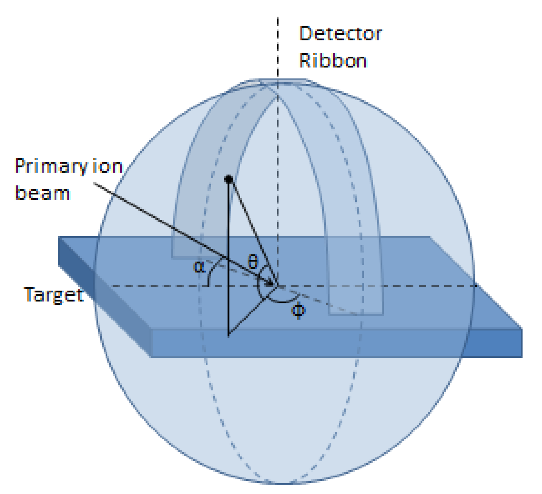
Figure 7.
Geometry of the sputtered ion ribbon detector after references [21,22]. Ions impacting the detector ribbon are counted with identification of the detection angle (θ): θ is the polar angle between the target surface and the vector from the ribbon detector center to the detection point on the ribbon, α is the incidence angle of the primary ion beam with respect to the target surface, and φ is the azimuthal angle in the target plane.

Figure 8.
Full θ-φ 2D angular distributions for α = 19° (a), α = 60° (b), and α = 90° (c): α is the incidence angle, θ is the polar angle, and φ is the azimuthal angle, as defined in Figure 7. The blue dots correspond to the H3O+ ions ejected from the sample surface.
Figure 8.
Full θ-φ 2D angular distributions for α = 19° (a), α = 60° (b), and α = 90° (c): α is the incidence angle, θ is the polar angle, and φ is the azimuthal angle, as defined in Figure 7. The blue dots correspond to the H3O+ ions ejected from the sample surface.


Figure 9.
Kinetic energy distribution of trapped ions (blue curve). The red solid line is a Maxwell–Boltzmann statistical distribution for T = 3 × 10⁴ K.
Figure 9.
Kinetic energy distribution of trapped ions (blue curve). The red solid line is a Maxwell–Boltzmann statistical distribution for T = 3 × 10⁴ K.

Disclaimer/Publisher’s Note: The statements, opinions and data contained in all publications are solely those of the individual author(s) and contributor(s) and not of MDPI and/or the editor(s). MDPI and/or the editor(s) disclaim responsibility for any injury to people or property resulting from any ideas, methods, instructions or products referred to in the content. |
© 2023 by the authors. Licensee MDPI, Basel, Switzerland. This article is an open access article distributed under the terms and conditions of the Creative Commons Attribution (CC BY) license (https://creativecommons.org/licenses/by/4.0/).
Share and Cite
MDPI and ACS Style
Costantini, J.-M.; Ogawa, T. Coulomb Spike Modelling of Ion Sputtering of Amorphous Water Ice. Quantum Beam Sci. 2023, 7, 7. https://doi.org/10.3390/qubs7010007
AMA Style
Costantini J-M, Ogawa T. Coulomb Spike Modelling of Ion Sputtering of Amorphous Water Ice. Quantum Beam Science. 2023; 7(1):7. https://doi.org/10.3390/qubs7010007
Chicago/Turabian StyleCostantini, Jean-Marc, and Tatsuhiko Ogawa. 2023. "Coulomb Spike Modelling of Ion Sputtering of Amorphous Water Ice" Quantum Beam Science 7, no. 1: 7. https://doi.org/10.3390/qubs7010007