

Automated Pulsed Magnet System for Neutron Diffraction Experiments at the Materials and Life Science Experimental Facility in J-PARC
1
Materials and Life Science Division, J-PARC Center, Japan Atomic Energy Agency (JAEA), Tokai, Ibaraki 319-1195, Japan
2
Research Institute for Interdisciplinary Science, Okayama University, Okayama 700-8530, Japan
3
Institute for Materials Research, Tohoku University, Miyagi 980-8577, Japan
*
Author to whom correspondence should be addressed.
Quantum Beam Sci. 2023, 7(1), 1; https://doi.org/10.3390/qubs7010001
Submission received: 29 November 2022
/
Revised: 21 December 2022
/
Accepted: 22 December 2022
/
Published: 27 December 2022
(This article belongs to the Special Issue Quantum Beam Science: Feature Papers 2022)
Abstract
:A pulsed magnet system has been developed as a new user-friendly sample environment equipment at the Materials and Life Science Experimental Facility in Japan Proton Accelerator Research Complex. It comprises a vacuum chamber, a 4 K closed-cycle refrigerator for samples, and a nitrogen bath made of a stainless-steel tube with a miniature solenoidal coil. The coil is cooled by liquid nitrogen supplied by an automatic liquid nitrogen supply system, and the sample is cooled by a refrigerator. This combination facilitates the automatic high magnetic field diffraction measurement for the user’s operation. A relatively large scattering angle 2θ is up to 42°, which is significantly wider than the previous setup. Neutron diffraction experiments were performed on a multiferroic TbMnO3 and the field dependence of the diffraction peaks was clearly observed. The new pulsed magnet system was established for a practical high magnetic field diffraction for the user program.
1. Introduction
Magnetic fields are one of the most beneficial environments for material research because they can directly influence the electron orbital motion and spin in materials without direct contact. Several new phase transitions and quantum phenomena have been discovered in high magnetic fields, particularly in strongly correlated electron systems. Neutron diffraction is a unique tool for directly determining the magnetic structure. Thus, magnetic fields are essential sample environments for the neutron diffraction studies of materials, such as magnetic compounds, superconductors, semiconductors, multiferroics, and others.
To meet the growing demand for high magnetic field applications for neutron diffractions, several high magnetic field environments have been developed in neutron facilities globally. Superconducting magnets have been used for neutron scattering experiments with magnetic fields of up to 17 T [1]. A 4 MW hybrid magnet comprised of superconducting and normal resistive magnets had been operated at the Extreme Magnet Field Facility (HFM) of the Helmholtz Center Berlin Institute (HZB) in Germany [2,3]. It had been generating magnetic fields of up to 26 T, but the reactor was recently shut down. There are projects to develop high Tc superconductor-based magnets beyond 20 T [4]. However, such steady field magnets necessitate a dedicated beam line for large stray fields. Thus, it may only be realized in future second target station projects in SNS and J-PARC [5,6]. Given this situation, a compact pulsed field magnet is advantageous for a practical user application because of its simple installation for the most existing beamlines, despite its restricted data accumulation capability for short pulsed widths and low repetition rates.
There have been several outcomes by pulsed magnetic field neutron diffractions in various facilities. A magnetic field of up to 30 T has been achieved using a compact pulsed magnet in a reactor neutron source at ILL by Yoshii et al. [7,8,9], a pulsed neutron source at SNS by Nojiri and Toft-Petersen [10,11], and a synchrotron source for x-ray diffraction and spectroscopy experiments by Islam and Noe II [12,13]. In these cases, the scattering angle, 2θ, is up to 30°, and a commercial liquid helium flow cryostat is used; the temperature of the samples is reduced to 2 K. A medium size coil of 42 T with a 250 kJ capacitor bank has been used to examine the successive phase transitions of multiferroics (LiNiPO4) [14,15] in J-PARC, but the scattering angle, 2θ, is confined to 22° for this setup. In addition, a pulsed magnet system with a magnetic field of up to 40 T has recently been developed in a reactor neutron source at ILL [16,17]. To generate long-pulsed fields, it employs a relatively large coil with an outer diameter of 280 mm and a 24 kV (1.15 MJ) power supply. In this instance, the use of long-pulsed fields is efficient because of the combination with the reactor neutrons. The scattering angle, 2θ, is 45°, and the temperature of the samples is cooled down to 2 K using a commercial liquid helium flow cryostat.
The highest field capability of the J-PARC medium-size pulsed magnet is very unique, but as a user facility, the wider scattering angle coverage and easy operation have been critical issues. To meet such requests, we have proceeded with the R&D program for a user-operated magnet system.
In the first step, we installed a compact capacitor bank of 16 kJ and combined it with a mini-horizontal solenoid magnet [18]. It generates a magnetic field of up to 30 T, and the maximum scattering angle, 2θ, is 30.6° for forward scattering. A commercial liquid helium flow cryostat is used to cool a sample to 2 K. The wide angle and the compactness made the experiments much easier, but it is still not suitable for the user’s operation for the necessities of the busy supply of cryogens of liquid nitrogen and liquid helium.
In the second stage of the development, we changed the sample cryostat from a bath-type cryostat to a closed-cycle Gifford–McMahon (GM) refrigerator (HE05RK, ULVAC Co., Ltd., Kanagawa, Japan) with the lowest temperature of 2.7 K [19]. This modification allows us to increase the scattering angle, 2θ, to 42° while keeping the maximum field of 30 T and operating the system automatically using the controller of the capacitor bank with minimal maintenance. Generally, liquid helium flow cryostat equipment can achieve temperatures as low as 2 K, but handling liquid helium is relatively difficult for users. This is why we developed a new pulsed magnet system using a closed-cycle refrigerator. Another critical point to consider is the automatic repetitive long-term operation. Previously, the bottleneck was manually supplying liquid nitrogen to the coil every few hours. Therefore, we recently introduced automatic liquid nitrogen supply equipment to achieve a fully automatic repetitive operation.
In this paper, we introduce the newly developed pulsed magnet system with a large scattering angle and the results of the neutron scattering experiments at the MLF in J-PARC to demonstrate the system’s utility.
2. Pulsed Magnet System
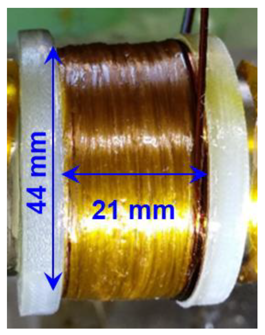
A pulsed magnet system with high magnetic pulsed fields of up to 30 T and 35 T has been developed for neutron scattering experiments. A high-tensile strength Cu–Ag alloy with 1 mmϕ (CA10-0PIWC-7, SWCC Showa Cable System Co., Ltd., Kanagawa, Japan) for the wire is used for a 30 T coil. The wire is wound around a coil bobbin made of thin enough (0.5 mmt) stainless-steel pipe to allow the magnetic field to perforate the coil’s center. It is wound with 12 layers to the bobbin, with each layer composed of 17 turns. The sum of the turns is 204. The glass cloths are wrapped to flatten the spacing between the layers, and the epoxy adhesive is applied during the winding process. Figure 1 depicts a photograph of a 30 T coil. It has inner and outer diameters of 14 and 44 mm, respectively, with an axial length of 21 mm. The wire’s ends are connected to the solid coaxial lead. The lead consists of a copper rod with a 3 mm diameter and a copper pipe with a 6 mm outer diameter with a 0.5 mm thickness. For electrical insulation, a PTFE tube is inserted between the copper rod and pipe. The lead length is approximately 1 m. The coil inductance and resistance were measured while immersed in liquid nitrogen using an LCR meter (3522–50, HIOKI) at 100 Hz and an mΩ Hi-Tester (3540, HIOKI), respectively. At 77 K, the inductance and resistance are measured to be 670 μH and 100 mΩ, respectively.
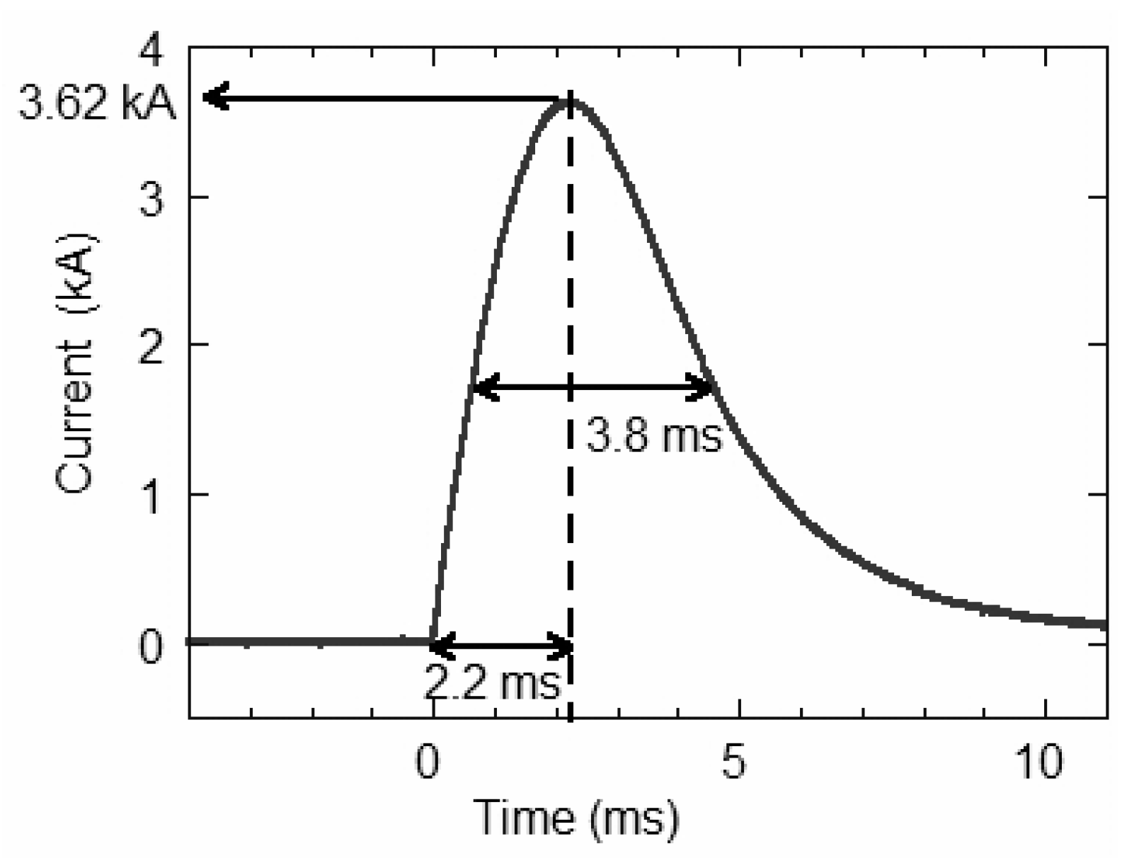
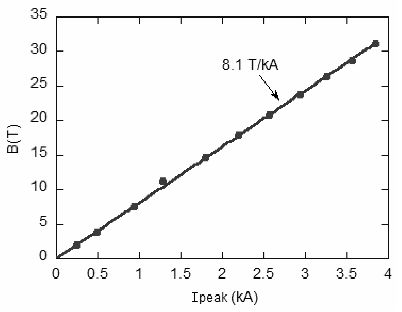
Subsequently, the magnetic field generation of the coil was tested. The magnetic field was measured with a pick-up coil [18]. The current was measured using a high-precision current transformer (Pearson, Model 1423). Figure 2 depicts a pulsed current passing through the coil. The pulse width was 3.8 ms at the half maximum. The rise time from the zero to peak current was about 2.2 ms. The peak current was 3.62 kA, corresponding to a magnetic flux density of about 30 T. Figure 3 depicts the relationship between the magnetic field (B) and peak current. The field-current coefficient is estimated to be 8.1 T/kA.
We recently developed a new pulsed coil up to 35 T that fits the same system. We used a rectangular wire of 1 × 1.5 mm2 made of Cu–Ag alloy and a Zylon fiber (Toyobo Co., Ltd., Osaka, Japan) reinforcement. It generates 35 T with 6.6 kA at 18.1 kJ charged energy. The detail of the new 35 T coil is shown elsewhere [20].
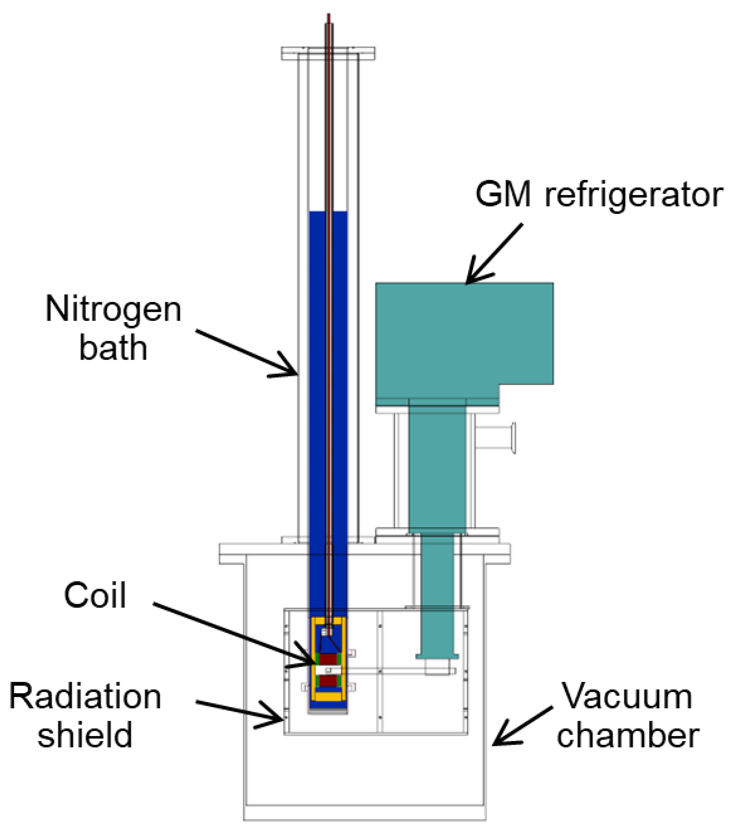
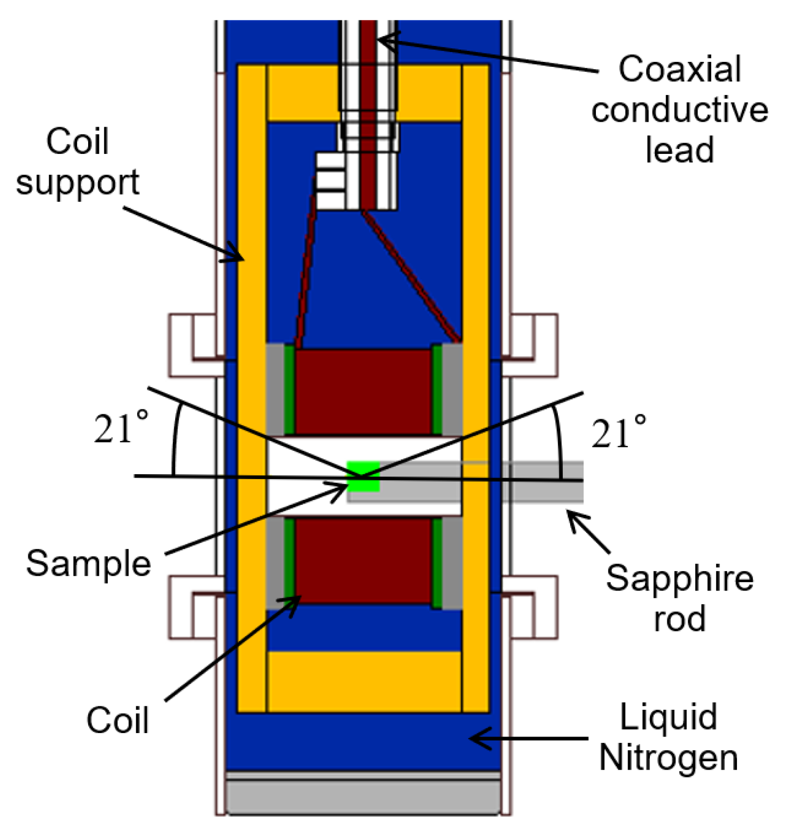
Figure 4 depicts a cross-sectional view of the pulsed magnet equipment. It comprises a vacuum chamber, a closed-cycle refrigerator for sample cooling down to 4 K, and a nitrogen bath made of a rectangular cross-section stainless-steel (SUS) tube. The coil is inserted in the nitrogen bath. The bottom part of the nitrogen bath surrounding the coil is a single wall, as opposed to the previous design of a double wall using a liquid helium flow cryostat for the first pulsed magnet [18]. It is enabled by the use of a closed-cycle refrigerator for sample cooling. This is an important factor in increasing the scattering angle. The coil in the nitrogen bath is immersed in liquid nitrogen to reduce the resistance and quickly remove the Joule heat generated by the coil’s pulsed current. Previously, it was compulsory to manually supply liquid nitrogen to the coil every few hours. Therefore, we newly introduced automatic liquid nitrogen supply equipment (LNAS, Value-impact Co., Ltd., Kanagawa, Japan) and a fully automatic repetitive operation could be achieved. The sample is attached to a 7 mmϕ single-crystalline sapphire rod that is connected to the GM refrigerator and cooled down to 4 K through heat conduction. Thermometers (Cernox, Lake Shore Cryotronics Inc., Westerville, OH, USA) are attached near the end of the sapphire rod and the second stage of the GM refrigerator. The sample and the sapphire rod are enclosed by an aluminum radiation shield of a 1 mm thickness to prevent a temperature rise. Figure 4 shows only the aluminum frame to which the shield is connected to show the inside. For the temperature control of the sample, a polyimide film insulation heater is wound around the second stage of the GM refrigerator. The temperature can be adjusted by a temperature controller (Model 336 Cryogenic Temperature Controller, Lake Shore Cryotronics, Inc., Westerville, OH, USA) which can be controlled approximately from 4 K to room temperature. We have validated that the temperature gradient between the sample and the refrigerator cold head is as small as 1.2 K. Figure 5 depicts an enlarged cross-sectional view around the coil. The sample is placed in the center of the coil. The scattering angle, 2θ, is 42°.
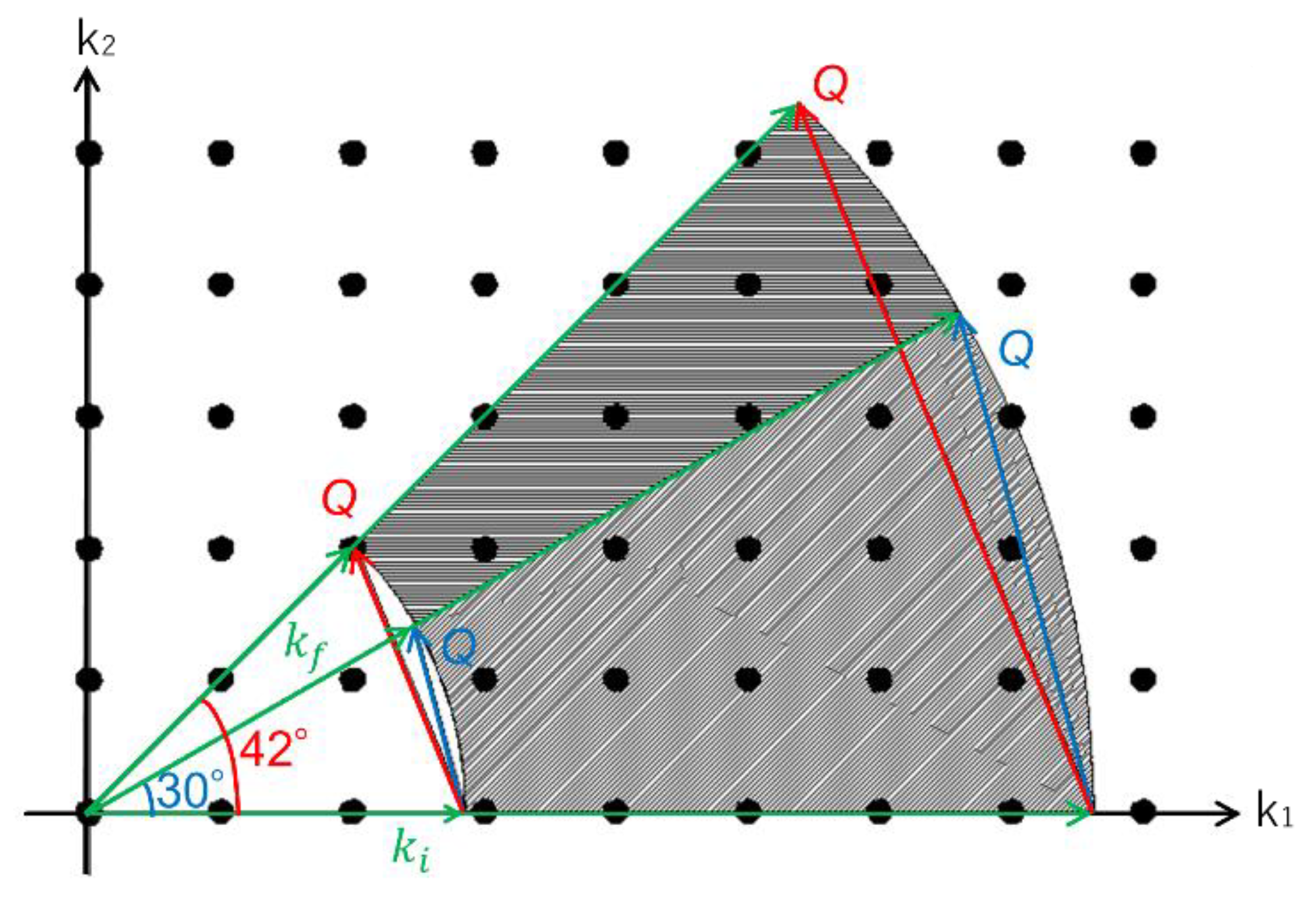
The maximum scattering angle of compact pulsed magnets in the neutron facilities as mentioned in the introduction was approximately 30°, but this equipment achieved 42°. This has the benefit of increasing the measured areas of the scattering vector, Q.
Bragg’s law is expressed using wave number of neutron, ki, as:
where is the sample’s interplanar spacing, and θ is the scattering angle.
Q can be expressed as:
The wave number, ki, can be written as follows:
where h is the Planck constant and m is the mass of a neutron, and L1 and are the distance and the time-of-flight from the neutron target to the sample, respectively.
For example, consider a neutron source diagnostic and test port (NOBORU) at the MLF. The L1 is 14 m and is about 0.5 to 40 ms since the MLF is 25 Hz.
The wavenumbers in Å−1 are calculated with the from Equation (3),
The in Å and Q in Å−1 is calculated with 2θ of 30° and 42° from Equations (1) and (2), giving the following results.
Figure 6 depicts a reciprocal space diagram. The diagonally hatched area is the measurable Q range at 30°. At 42°, it increases to the horizontal hatched area.
3. Demonstration Test of the Pulsed Magnet System on Neutron Scattering Experiments
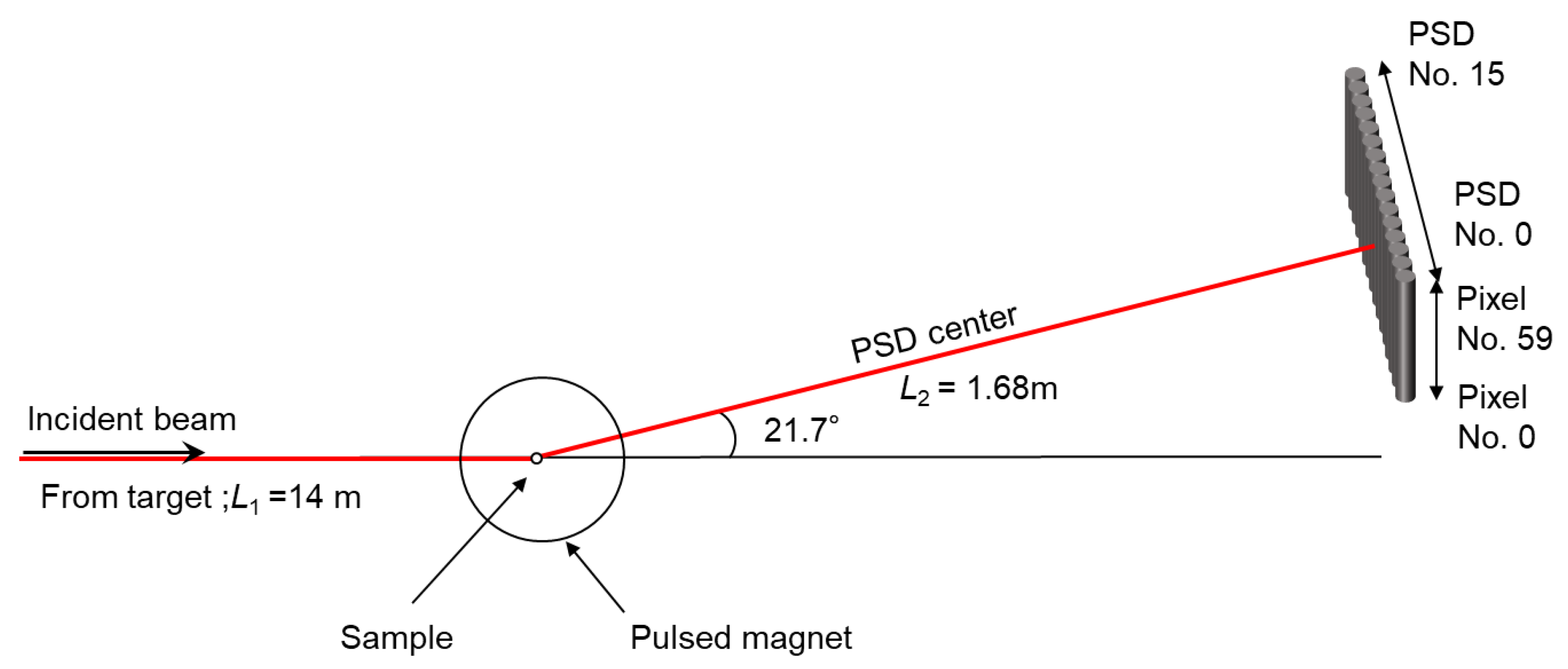
The pulsed magnet system was commissioned on NOBORU (BL10). Figure 7 depicts a schematic representation of the experimental setup. The pulsed magnet was positioned such that the neutron beam hit the sample’s center. The 3He gas position sensitive detector (PSD) tubes, which were thin cylinders with 1/2 inchϕ thickness and 0.68 m in length, were used for the neutron detector. It consists of 16 PSD tubes with 60 pixels each. It was positioned 1.68 m (L2) downstream to cover a range of approximately 21.7 3.47°. In the height direction, the center of the PSD was centered at the same height as the sample. The angle range of one PSD and pixel was about 0.43° and 0.34°, respectively.
The time-of-flight from the neutron target to the detector is defined as:
where L2, 1.68 m is the distance from the sample to the detector.
A single-crystalline multiferroic TbMnO3 [21,22,23] was used as a test sample. TbMnO3 is a multiferroic material that coexists in magnetic and ferroelectric orders. For example, it is expected to be a multifunctional and high-performance next-generation electric/magnetic device.
At zero magnetic fields, the magnetic moments of Mn in TbMnO3 are incommensurate, and the propagation wave vector (0, kMn, 1) in the Pbnm orthorhombic unit is (0, 0.28, 1) below 28 K [24,25]. In the magnetic field of 30 T, they become commensurate and show a propagation wave vector of (0, 0.25, 1). As a demonstration of the pulsed magnet system, the change in the TOF spectrum of the Mn moments with and without a magnetic field was experimentally validated. The sample size is approximately 4.5 × 4 × 3.5 mm3. It was placed such that the magnetic field was to be applied along the a-axis. A motor (DGM200R-AZMC, Oriental Motor Co., Ltd., Tokyo, Japan) attached beneath the vacuum chamber rotates the sample and cryostat horizontally. It can be rotated in 0.01° increments. The motor rotation was appropriately adjusted so that the scattered neutrons hit the PSD array near the center.
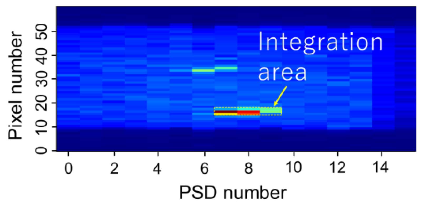
Figure 8 and Figure 9 show the detector image at 30 T and 0 T, respectively. The MLF-developed UTSUSEMI package is used to reduce and visualize the data [26]. The neutron beam power was about 620 kW. The neutron counts at 30 T are integrated for 40 identical pulsed-field shots, which took about 5 h because one shot was applied every 7 min to remove the coil heat with liquid nitrogen.
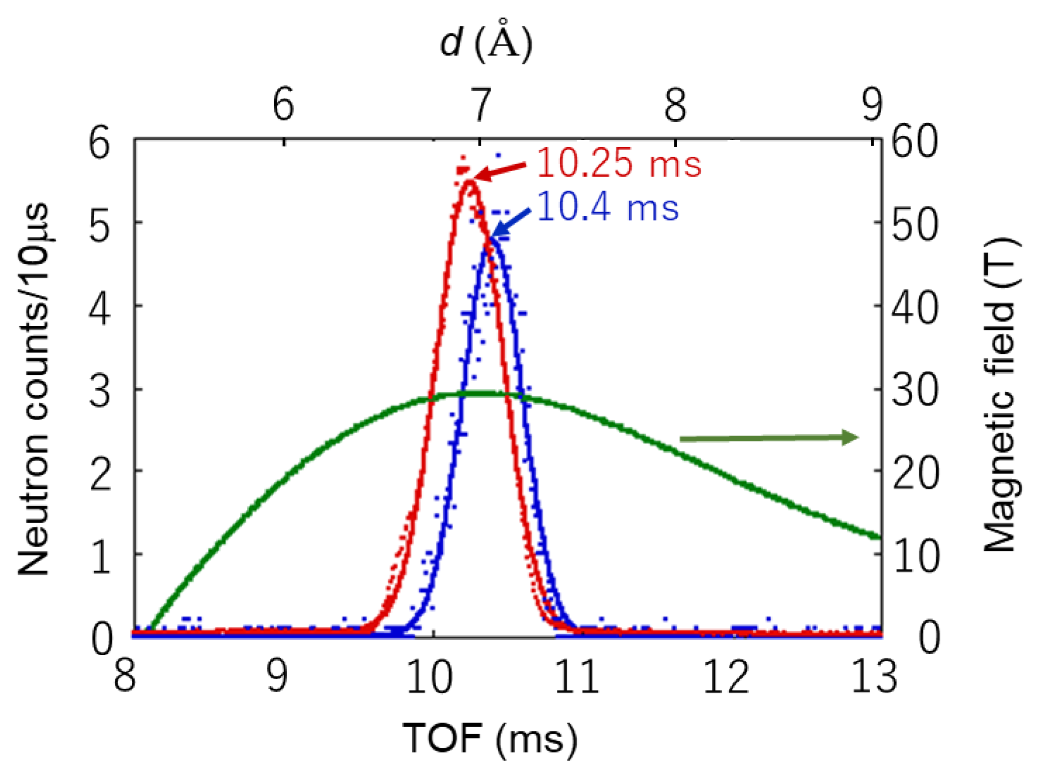
Integrating neutron counts at 30 T in the area covered by the yellow dashed line in Figure 8 yields the TOF spectrum of the blue dot, as shown in Figure 10. The horizontal axis represents the TOF and interplanar spacing (d), while the vertical axis represents the neutron counts. The TOF bin of the histogram is 10 μs. Additionally, the integrating neutron counts at 0 T in the area covered by the yellow dashed line in Figure 9 yield the TOF spectrum of the red dot, as shown in Figure 10. Because the neutron counts are integrated for approximately 10,000 incident beam pulses (approximately 7 min) at 0 T, the count number displayed in Figure 10 is reduced to 1/100 to match the count number of 40 shots at 30 T. Figure 10 is also depicted as an example of a pulsed magnetic field waveform applied to a sample. A timing controller [18] adjusts the time delay of the magnetic field pulse in the experiments so that the magnetic field peak (30 T) coincides with the Bragg peak. To make the figure easier to understand, the time of the pulsed magnetic field waveform is delayed by 1.12 ms, that is the peak of the TOF spectrum from the sample to the detector in Figure 10.
There is a Bragg peak signal in Figure 10 that corresponds to the propagation wave vector (0, 0.28, 1) of the Mn moments at 0 T. The TOF of the Bragg peak is estimated to be approximately 10.25 ms using the Gaussian function, which is represented by the solid line in red. The TOF is validated to be as follows using Bragg’s law:
where λ is the neutron wavelength, dhkl is the sample’s interplanar spacing, and θ is the scattering angle. Using Equations (4) and (5), when 2θ is 21.35°, the TOF is calculated to be approximately 10.25 ms, which is consistent with the experimental result.
There is also a Bragg peak signal that corresponds to the propagation wave vector (0, 0.25, 0) of the Mn moments at 30 T. The TOF of the Bragg peak is calculated to be approximately 10.4 ms by Gaussian fits shown as the solid line in blue in Figure 10, which is also consistent with the calculation using Equations (4) and (5).
As shown in Figure 10, the magnetic field dependence of the diffraction peaks with and without a magnetic field was clearly observed using the pulsed magnet system.
4. Conclusions
A new pulsed magnet system for high magnetic fields of up to 30 T and 35 T has been established. It comprises a vacuum chamber, a closed-cycle refrigerator for sample cooling down to 4 K, and a nitrogen bath made of a SUS tube in which a mini solenoidal coil was inserted. The relatively large scattering angle, 2θ, is up to 42°. Using automatic liquid nitrogen supply equipment, the fully automatic repetitive operation was achieved.
Neutron beam scattering experiments on a neutron source diagnostic and test port (NOBORU (BL10)) at the MLF were conducted using the pulsed magnet system to demonstrate its effectiveness. We clearly observed the magnetic field dependence of the diffraction peaks with and without the magnetic field.
Conclusively, the new pulsed magnet system has been successfully operated, allowing us to begin conducting experiments with some users.
Author Contributions
Conceptualization, M.W. and H.N.; Validation, T.K.; investigation, M.W.; writing—original draft, M.W.; writing—review and editing, T.K. and H.N.; Supervision, H.N. All authors have read and agreed to the published version of the manuscript.
Funding
This research received no external funding.
Data Availability Statement
Not applicable.
Acknowledgments
The experiments at the MLF in J-PARC were performed under the user programs (Proposal No. 2019P0201 and 2020P0201). We acknowledge the support from joint research between JAEA and Tohoku university. And we acknowledge the support from Global Institute for Materials Research Tohoku (GIMRT) in Tohoku UNiversity. (Proposals numbers are 15K0080, 16K0050, 17K0071, 18K0015, 19K0046, 20K0010, 202012-RDKGE-0046 and 202112-RDKGE-0043.) H.N. acknowledges the support from KAKENHI 19H0647&23224009 and supply of Zylon fiber by Toyobo Co., Ltd.
Conflicts of Interest
The authors declare no conflict of interest.
References
- Meissner, M.; Smeibidl, P. Neutron scattering at BENSC under extreme conditions: Up to 17 tesla and down to 25 mK. Neutron News 2001, 12, 12–18. [Google Scholar] [CrossRef]
- Steiner, M.; Tennant, D.A.; Smeibidl, P. New high field magnet for neutron scattering at Hahn-Meitner Institute. J. Phys. Conf. Ser. 2006, 51, 470–474. [Google Scholar] [CrossRef] [Green Version]
- Smeibidl, P.; Tennant, A.; Bird, H.E.M. Neutron scattering at highest magnetic fields at the Helmholtz Centre Berlin. J. Low Temp. Phys. 2010, 159, 402–405. [Google Scholar] [CrossRef]
- Awaji, S.; Watanabe, K.; Oguro, H.; Miyazaki, H.; Hanai, S.; Tosaka, T.; Ioka, S. First performance test of a 25 T cryogen-free superconducting magnet. Supercond. Sci. Technol. 2017, 30, 065001. [Google Scholar] [CrossRef]
- Second Target Station Conceptual Design Report Volume 1: Overview. Technical and Experiment Systems. 2020. Available online: https://neutrons.ornl.gov/sites/default/files/STS_CDR_Vol1_v2.pdf (accessed on 21 December 2022).
- Conceptual Design Report of 2nd Target Station of J-PARC MLF. 2020. Available online: https://j-parc.jp/researcher/MatLife/ja/publication/files/TS2CDR.pdf (accessed on 21 December 2022). (In Japanese).
- Yoshii, S.; Ohoyama, K.; Kurosawa, K.; Nojiri, H.; Matsuda, M.; Frings, P.; Duc, F.; Vignolle, B.; Rikken, G.L.J.A.; Regnault, L.P.; et al. Neutron Diffraction Study on the Multiple Magnetization Plateaus in TbB4 under Pulsed High Magnetic Field. Phys. Rev. Lett. 2009, 103, 077203. [Google Scholar] [CrossRef]
- Matsuda, M.; Ohoyama, K.; Yoshii, S.; Nojiri, H.; Frings, P.; Duc, F.; Vignolle, B.; Rikken, G.; Regnault, L.-P.; Lee, S.-H.; et al. Universal Magnetic Structure of the Half-Magnetization Phase in Cr-Based Spinels, January 2010. Phys. Rev. Lett. 2010, 104, 047201. [Google Scholar] [CrossRef] [Green Version]
- Kuwahara, K.; Yoshii, S.; Nojiri, H.; Aoki, D.; Knafo, W.; Duc, F.; Fabrèges, X.; Scheerer, G.; Frings, P.; Rikken, G.; et al. Magnetic structure of phase II in U(Ru0.96Rh0.04)2Si2 determined by neutron diffraction under pulsed high magnetic fields. Phys. Rev. Lett. 2013, 110, 216406. [Google Scholar] [CrossRef] [Green Version]
- Nojiri, H.; Yoshii, S.; Yasui, M.; Okada, K.; Matsuda, M.; Jung, J.-S.; Kimura, T.; Santodonato, L.; Granroth, G.E.; Ross, K.A.; et al. Neutron Laue Diffraction Study on the Magnetic Phase Diagram of Multiferroic MnWO4 under Pulsed High Magnetic Fields. Phys. Rev. Lett. 2011, 106, 237202. [Google Scholar] [CrossRef] [Green Version]
- Toft-Petersen, R.; Fogh, E.; Kihara, T.; Jensen, J.; Fritsch, K.; Lee, J.; Granroth, G.; Stone, M.; Vaknin, D.; Nojiri, H.; et al. Field-Induced Reentrant Magnetoelectric Phase in LiNiPO4. Phys. Rev. B 2017, 95, 064421. [Google Scholar] [CrossRef] [Green Version]
- Islam, Z.; Capatica, D.; Ruff, J.P.C.; Das, R.K.; Trakhtenberg, E.; Nojiri, H.; Narumi, Y.; Welp, U.; Canfield, P.C. A single-solenoid pulsed-magnet system for single-crystal scattering studies. Rev. Sci. Instrum. 2012, 83, 035101. [Google Scholar] [CrossRef]
- Noe, G.T., II; Nojiri, H.; Lee, J.; Woods, G.L.; Léotin, J.; Kono, J. A table-top, repetitive pulsed magnet for nonlinear and ultrafast spectroscopy in high magnetic fields up to 30 T. Rev. Sci. Instrum. 2013, 84, 123906. [Google Scholar] [CrossRef] [PubMed] [Green Version]
- Fogh, E.; Kihara, T.; Toft-Petersen, R.; Bartkowiak, M.; Narumi, Y.; Prokhnenko, O.; Miyake, A.; Tokunaga, M.; Oikawa, K.; Sørensen, M.K.; et al. Magnetic structures and quadratic magnetoelectric effect in LiNiPO4 beyond 30 T. Phys. Rev. B 2020, 101, 024403. [Google Scholar] [CrossRef] [Green Version]
- Fogh, E.; Kihara, T.; Toft-Petersen, R.; Sørensen, M.K.; Suto, H.; Matsuda, Y.; Narumi, Y.; Oikawa, K.; Nojiri, H.; Christensen, N.B. Neutron Diffraction up to 41.2 T—The New Record Established at the J-PARC NOBORU Beamline; MLF Annual Report; Materials and Life Science Division, J-PARC Center: Ibaraki, Japan, 2015; pp. 42–43. Available online: https://j-parc.jp/researcher/MatLife/ja/publication/files/MLF-AR-2015.pdf (accessed on 21 December 2022).
- Duc, F.; Tonon, X.; Billette, J.; Rollet, B.; Knafo, W.; Bourdarot, F.; Béard, J.; Mantegazza, F.; Longuet, B.; Lorenzo, J.E.; et al. 40-Tesla pulsed-field cryomagnet for single crystal neutron diffraction. Rev. Sci. Instrum. 2018, 89, 053905. [Google Scholar] [CrossRef] [PubMed] [Green Version]
- Knafo, W.; Duc, F.; Bourdarot, F.; Kuwahara, K.; Nojiri, H.; Aoki, D.; Billette, J.; Frings, P.; Tonon, X.; Lelièvre-Berna, E.; et al. Field-induced spin-density wave beyond hidden order in URu2Si2. Nat. Commun. 2016, 7, 13075. [Google Scholar] [CrossRef]
- Watanabe, M.; Nojiri, H. Pulsed magnet system at MLF in J-PARC. J. Neutron Res. 2019, 21, 39–45. [Google Scholar] [CrossRef]
- Available online: https://www.ulvac-cryo.com/products-en/refrigerator-en/cryocoolers/he05/?lang=en (accessed on 28 November 2022).
- Watanabe, M.; Nojiri, H. Development of pulsed magnet system up to 35 Tesla at MLF in J-PARC. In International Workshop at the Institute for Materials Research (IMR) in Tohoku University; High Magnetic Field Forum: Miyagi, Japan; p. 19. Available online: http://www.ahmf.sci.osaka-u.ac.jp/forum2022/HMF-workshop2022_abstract_ver01.pdf (accessed on 21 December 2022).
- Quezel, S.; Tcheou, F.; Rossat-Mignod, J.; Quezel, G.; Roudaut, E. Magnetic structure of the perovskite-like compound TbMnO3. Phys. B 1977, 86–88, 916–918. [Google Scholar] [CrossRef]
- Kimura, T.; Goto, T.; Shintani, H.; Ishizaka, K.; Arima, T.; Tokura, Y. Magnetic control of ferroelectric polarization. Nature 2003, 426, 55–58. [Google Scholar] [CrossRef]
- Kimura, T.; Lawes, G.; Goto, T.; Tokura, Y.; Ramirez, A. Magnetoelectric phase diagrams of orthorhombic RMnO3 (R = Gd, Tb, and Dy). Phys. Rev. B 2005, 71, 224425. [Google Scholar] [CrossRef]
- Strempfer, J.; Bohnenbuck, B.; Zegkinoglou, I.; Aliouane, N.; Landsgesell, S.; Zimmermann, M.v.; Argyriou, D.N. Magnetic-field-induced transitions in multiferroic TbMnO3 probed by resonant and nonresonant X-ray diffraction. Phys. Rev. B 2008, 78, 024429. [Google Scholar] [CrossRef] [Green Version]
- Senff, D.; Link, P.; Aliouane, N.; Argyriou, D.N.; Braden, M. Field dependence of magnetic correlations through the polarization flop transition in multiferroic TbMnO3: Evidence for a magnetic memory effect. Phys. Rev. B 2008, 77, 174419. [Google Scholar] [CrossRef]
- Inamura, Y.; Nakatani, T.; Suzuki, J.; Otomo, T. Development status of software ‘Utsusemi’ for Chopper Spectrometers at MLF. J. Phys. Soc. Jpn. 2013, 82, SA031. [Google Scholar] [CrossRef]
Figure 1.
Photograph of the coil.

Figure 2.
Pulsed current passing through the coil.

Figure 3.
Relationship between magnetic field (B) and peak current.

Figure 4.
Cross-sectional view of the new pulsed magnet system.

Figure 5.
Enlarged cross-sectional view around the coil.

Figure 6.
Reciprocal space map.

Figure 7.
Schematic representation of the experimental setup.

Figure 8.
Detector image at 30 T.

Figure 9.
Detector image at 0 T.

Figure 10.
TOF spectrum and interplanar spacing (d) with (30 T, in blue) and without (in red) the magnetic field and an example of the pulsed magnetic field waveform (in green) applied to the sample.
Figure 10.
TOF spectrum and interplanar spacing (d) with (30 T, in blue) and without (in red) the magnetic field and an example of the pulsed magnetic field waveform (in green) applied to the sample.

Disclaimer/Publisher’s Note: The statements, opinions and data contained in all publications are solely those of the individual author(s) and contributor(s) and not of MDPI and/or the editor(s). MDPI and/or the editor(s) disclaim responsibility for any injury to people or property resulting from any ideas, methods, instructions or products referred to in the content. |
© 2022 by the authors. Licensee MDPI, Basel, Switzerland. This article is an open access article distributed under the terms and conditions of the Creative Commons Attribution (CC BY) license (https://creativecommons.org/licenses/by/4.0/).
Share and Cite
MDPI and ACS Style
Watanabe, M.; Kihara, T.; Nojiri, H. Automated Pulsed Magnet System for Neutron Diffraction Experiments at the Materials and Life Science Experimental Facility in J-PARC. Quantum Beam Sci. 2023, 7, 1. https://doi.org/10.3390/qubs7010001
AMA Style
Watanabe M, Kihara T, Nojiri H. Automated Pulsed Magnet System for Neutron Diffraction Experiments at the Materials and Life Science Experimental Facility in J-PARC. Quantum Beam Science. 2023; 7(1):1. https://doi.org/10.3390/qubs7010001
Chicago/Turabian StyleWatanabe, Masao, Takumi Kihara, and Hiroyuki Nojiri. 2023. "Automated Pulsed Magnet System for Neutron Diffraction Experiments at the Materials and Life Science Experimental Facility in J-PARC" Quantum Beam Science 7, no. 1: 1. https://doi.org/10.3390/qubs7010001