
Numerical Investigation of Pre-Stressed Reinforced Concrete Railway Sleeper for High-Speed Application
 , , , , , ,
Abstract
:1. Background
- to sustain forces from rails and transfer them to the ballast bed with the possible highest uniform manner;
- to provide support and fixing possibilities for the rail foot and fastenings;
- to ensure suitable electrical insulation between rails;
- to guarantee track gauge and rail inclination (mainly 1:20 and 1:40);
- to be resistant to mechanical effects and weathering during their lifetime.
- to distribute and transmit forces to the ballast (perpendicular axle loads, longitudinal forces within the rails, centrifugal horizontal forces);
- to establish and maintain the track gauge;
- to hold the rails in height as well as a longitudinal direction;
- to secure the track under construction;
- to dampen rail vibrations;
- to reduce the influence of impact waves and sounds on the environment.
- twin-block sleeper;
- “longitudinal” sleeper;
- monoblock sleeper;
- slab sleeper;
- frame sleeper;
- other special sleepers, e.g., turnout sleeper, etc.
- timber (or wooden) sleepers:
- o
- hardwood sleepers (e.g., beech, oak, tropical varieties);
- o
- softwood sleepers (e.g., pinewood);
- steel sleepers;
- concrete sleepers;
- o
- reinforced concrete sleepers (RC sleepers);
- o
- pre-stressed reinforced concrete sleepers (PRESRC sleepers);
- o
- post-stressed reinforced concrete sleepers without bonding technology (POSTSRC sleepers without bonding);
- o
- post-stressed reinforced concrete sleepers with bonding technology (POSTSRC sleepers with bonding);
- plastic and/or composite sleepers [14];
- other special, modern materials.
- increasing the strength of the RC sleepers with the application of different materials such as concrete mixtures or inclusions, geometry, as well as technologies:
- o
- steel fibers and graphene oxide [15];
- o
- o
- o
- rubber-concrete [23];
- o
- macro synthetic fiber-reinforced concrete (MSFRC) [24];
- o
- metal-matrix composites [25];
- o
- steel fibers with straight and hooked geometry [26];
- o
- palm oil fuel ash as supplement material (instead) of cement [27];
- o
- preplaced aggregate concrete [28];
- o
- ladder tracks [29];
- investigation of RC sleepers in the case of an environment with high humidity [32];
- investigation of longitudinal stiffness of the ballasted railway tracks [35];
- the development of new laboratory test methods and arrangements for sleeper bending tests [36];
- the application of waste bi-block concrete sleepers for the improvement and reinforcing of railway earthwork [37];
- the consideration of changing the strength and elastic moduli of concretes during the lifespan of the sleepers [38];
- investigation of settlements of ballasted tracks with increased sleeper space [42];
- taking into consideration the noise and/or vibration reduction with different sleepers [27];
- development of RC sleepers for a 40 ton axle load [22];
- examination of environmentally friendly production technology [43];
- investigation of fault production of RC sleepers and the possible reasons for it [44];
- development and analysis of RC sleepers of tramway tracks [31];
- analysis of the debonding effect of twin-block slab tracks [45];
- analysis of the features of the stress-strain state of the dual gauge track with a special design of reinforced concrete sleepers with the simultaneous fastening of four rails [48].The methods listed below have been applied in the papers:
- numerical modeling (MATLAB, etc.) [39];
- analytical modeling [30];
2. Methods
3. Results
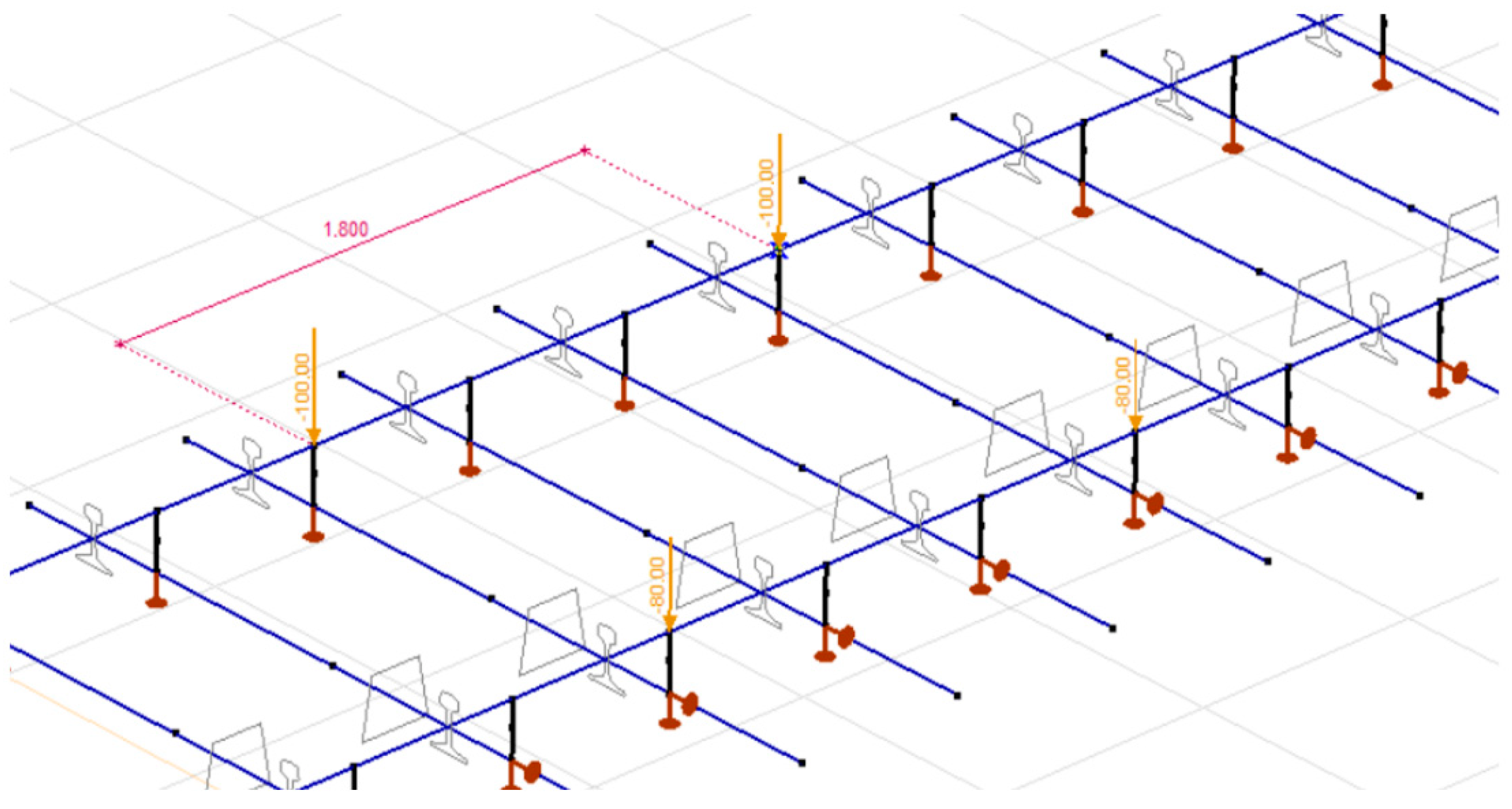
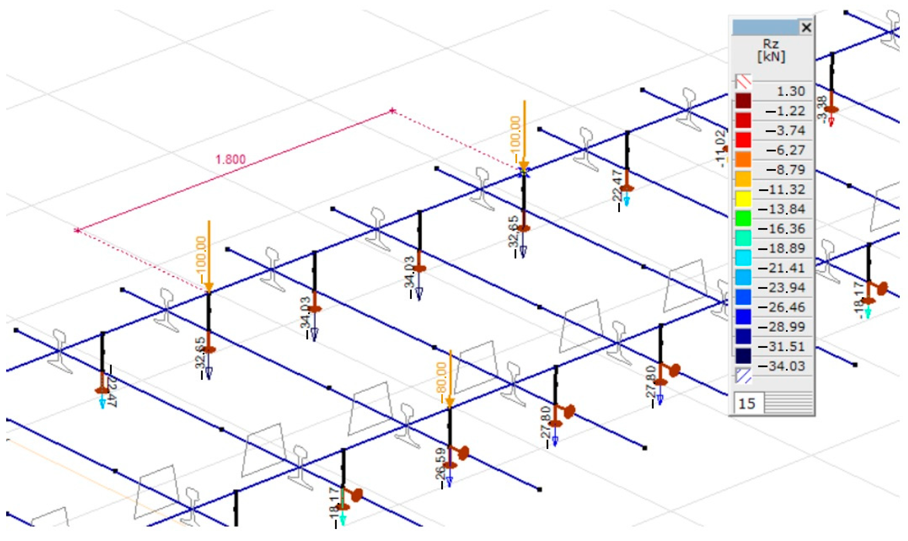
3.1. Determination of Mechanical Inner Forces of the Sleeper Using AxisVM finite Element Software
- Kz: vertical spring constant for one rail [kN/m];
- A: supporting contact area regarding one rail [mm2].
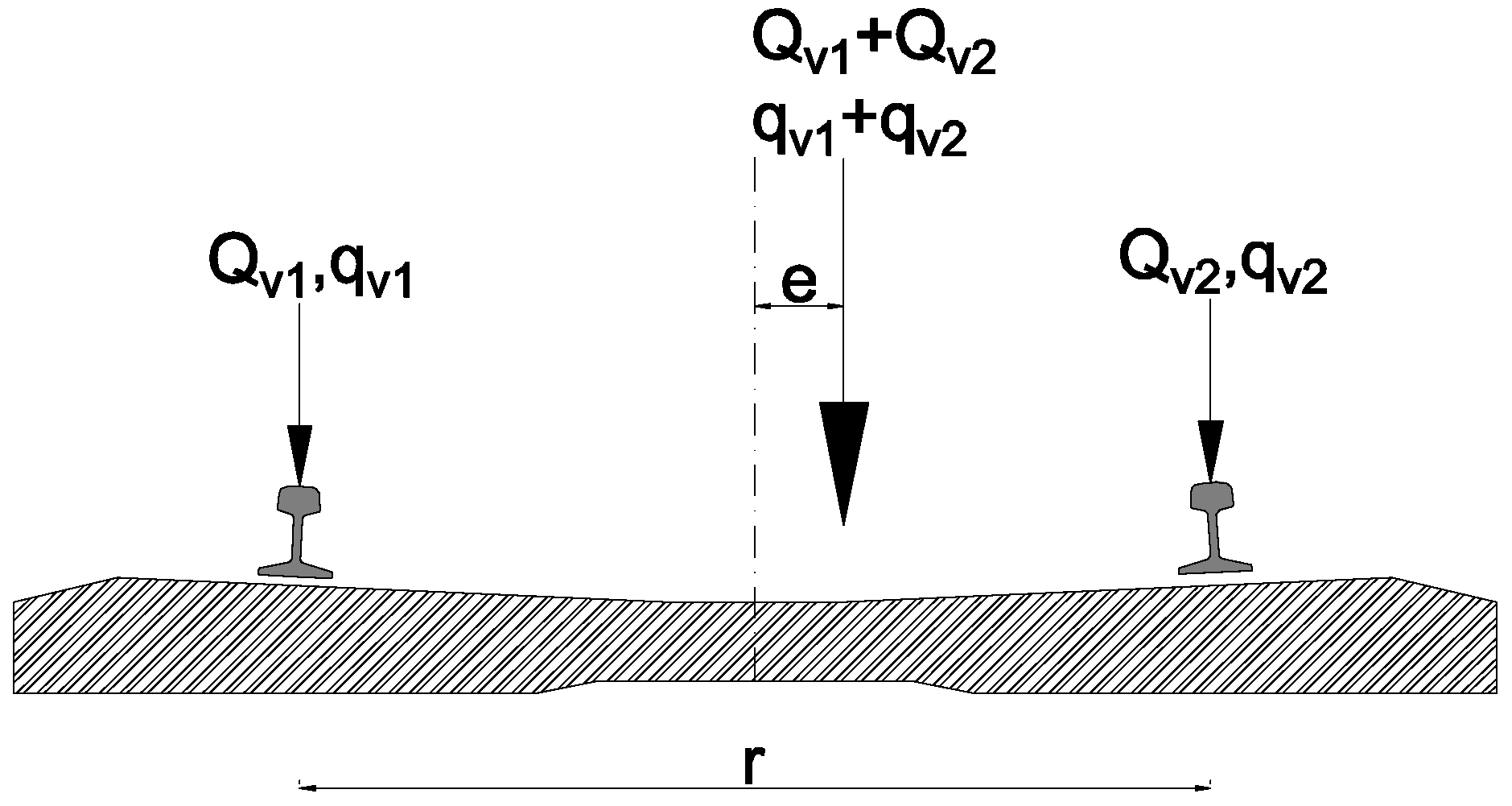
- Qv1: one of the vertical wheel forces in a wheelset [kN];
- Qv2: the other vertical wheel force in the same wheelset [kN];
- Qv1 + Qv2: vertical axle force (load) in the mentioned wheelset, the sum of them is Qv [kN].
- e: the random eccentricity in [m] or in [mm] units;
- r: distance between rail centers; its nominal value is 1.5 m if there is a standard track gauge (1.435 m);
- qv1 and qv2: vertical force acting on each rail [kN].
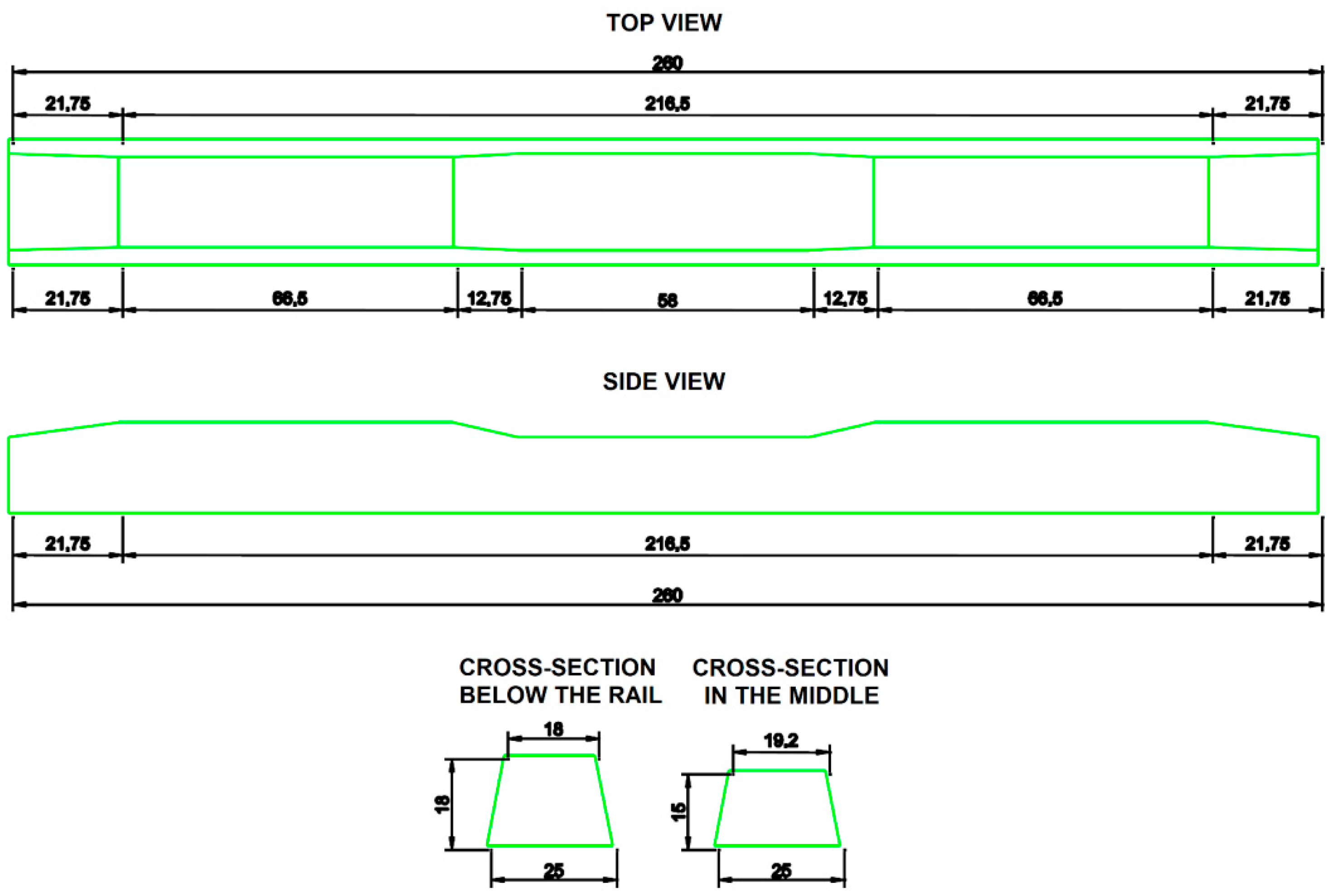
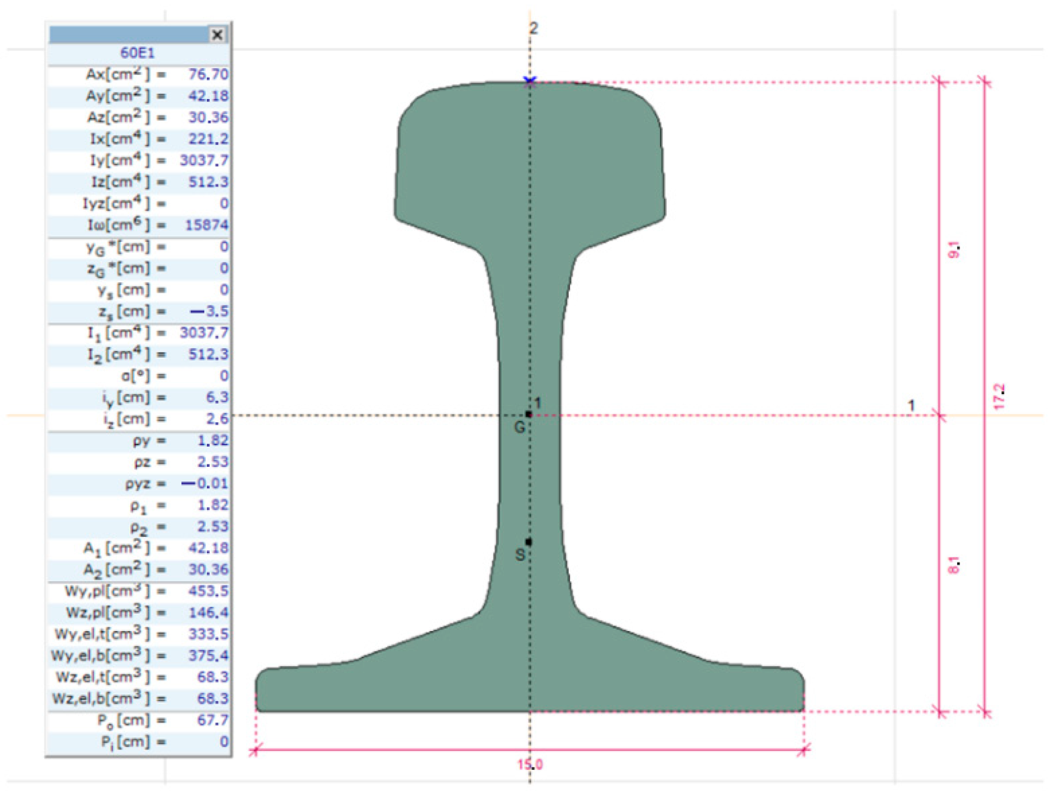
- s: the width of the rail foot in [m] unit, in the case of the 60E1 rail profile s = 0.15 m;
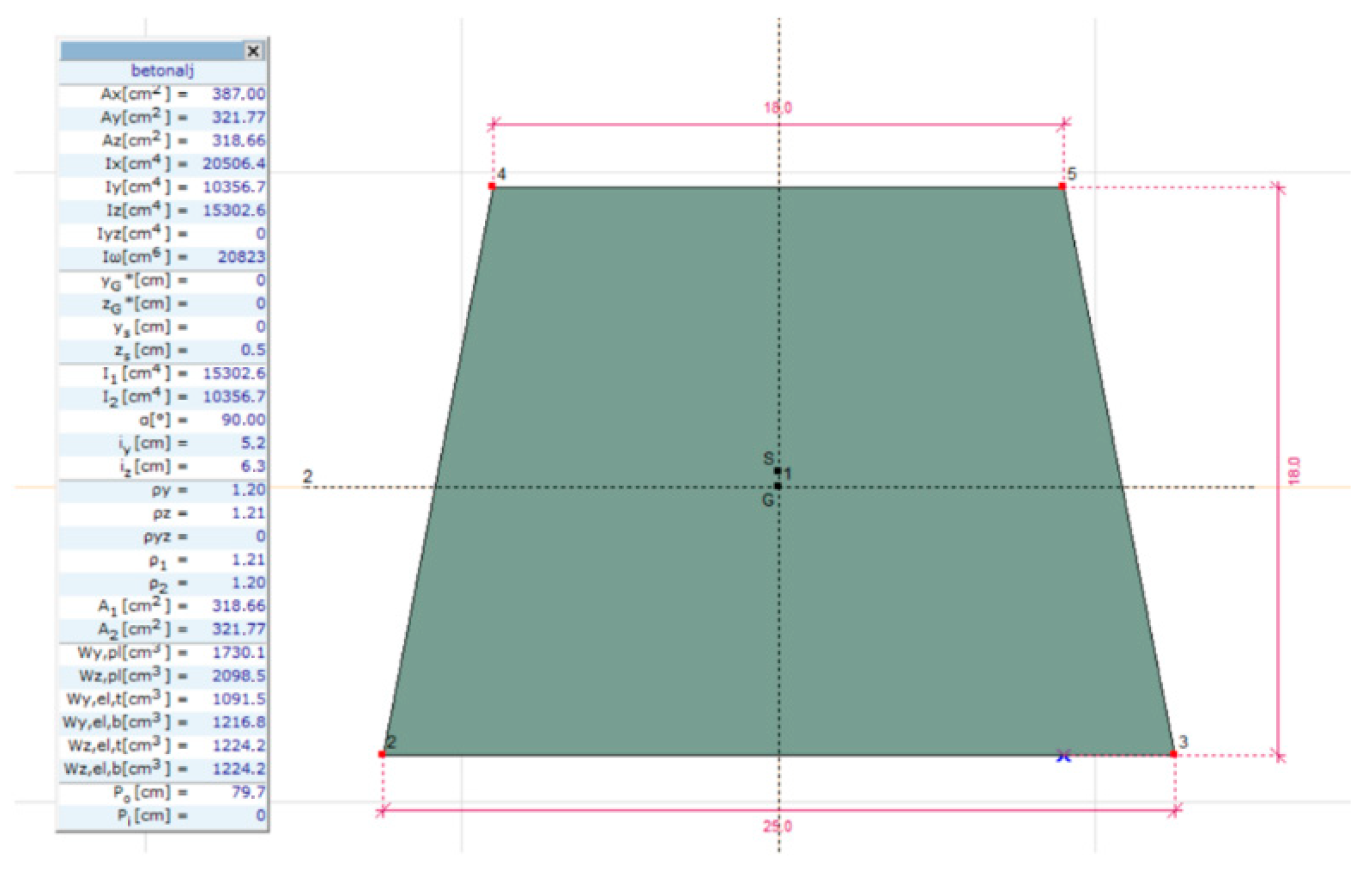
- d: the thickness of the sleeper under the rail foot’s center in [m] unit, 0.180 m was considered in this paper (this value was determined with the help of safety due to the trapezoid cross-sectional shape).
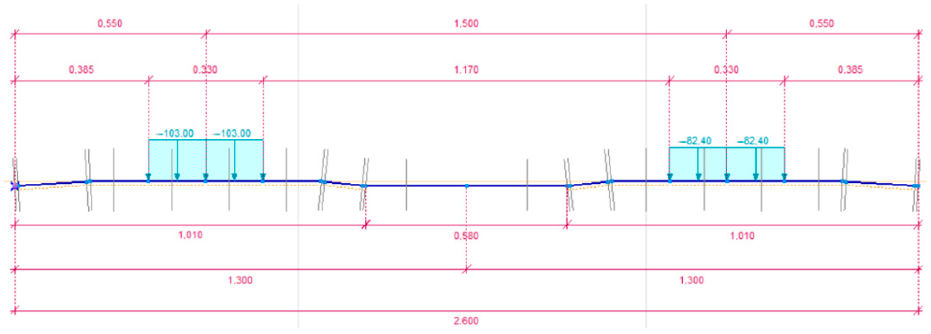
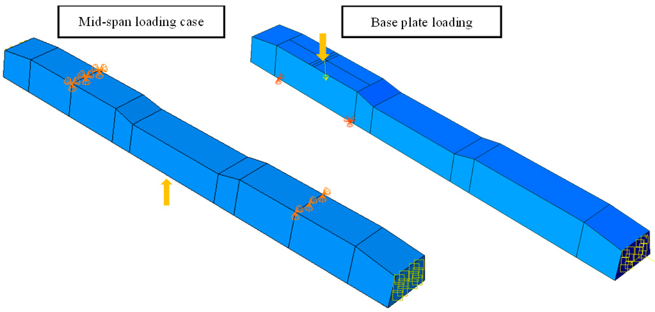
- Case #1: 90% of the specified maximum load (Qv’) is applied to both parts under the rail (central load, see Equation (8));
- Case #2: one part below the rail foot receives the maximum load, while the other gets 80% of the load (eccentric load, based on a wheel load distribution of 1.00:1.25 = 0.80:1.00).
- kz: longitudinal (or in others word, lengthwise) spring constant in the [kN/m/m] unit;
- b1: width of the sleeper bottom in [mm] unit.
- V: the allowed speed on the track in [km/h] unit.
- n: track condition parameter, n = 0.2 is considered;
- t: Student distribution parameter, 99.7% calculation accuracy is taken into consideration when t = 3.0.
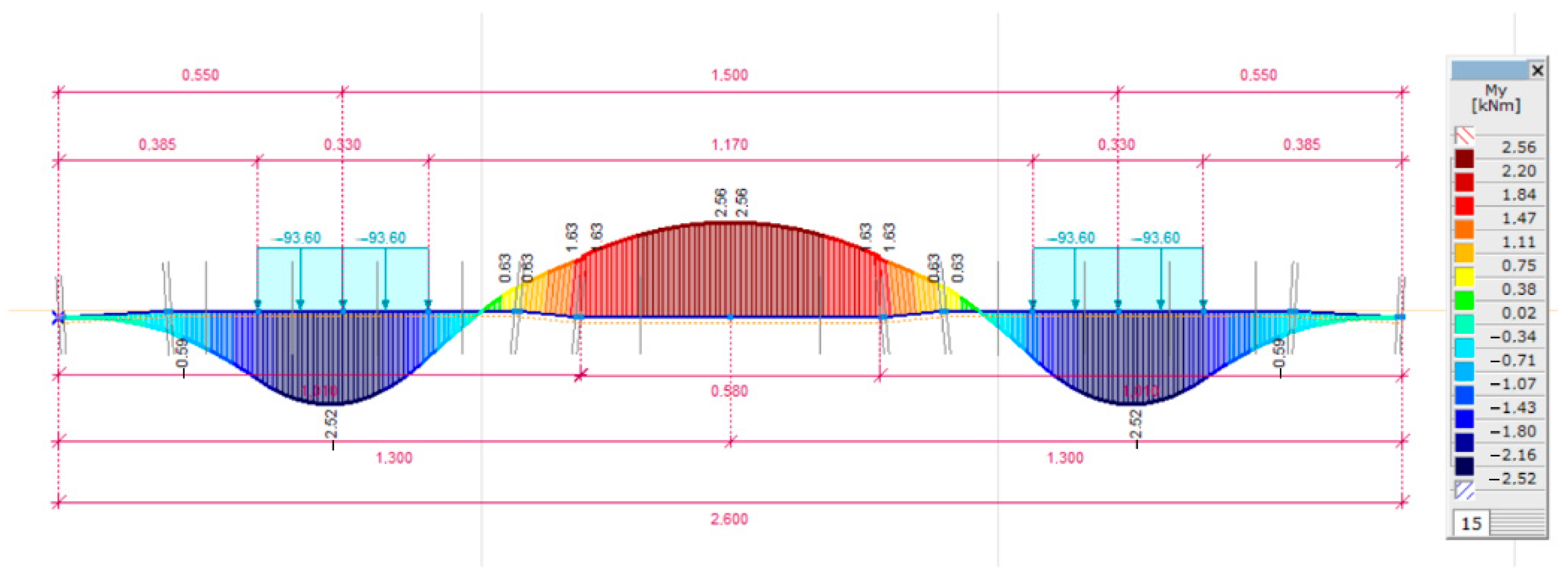
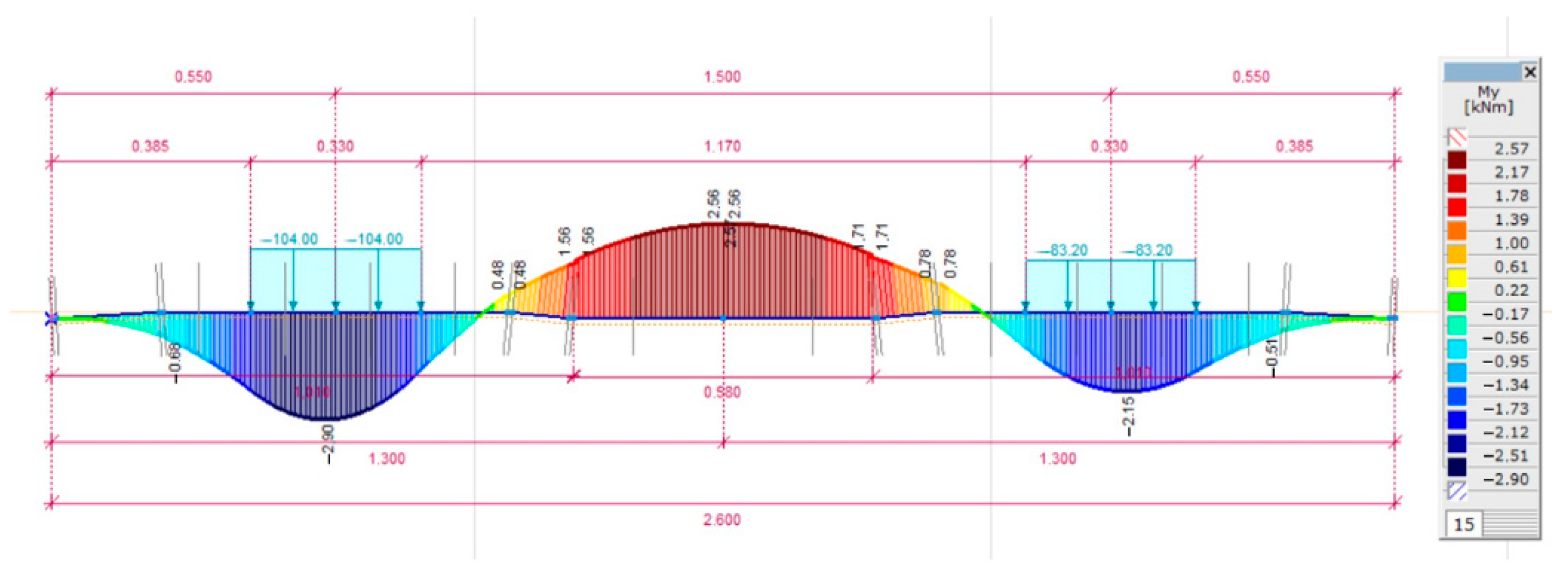
- Md: the design value of the bending moment in [kNm] units;
- M: the mean value of the bending moment in [kNm] units;
- Φ: dynamic factor based on Equation (16);
- Γ: based on Equation (10).
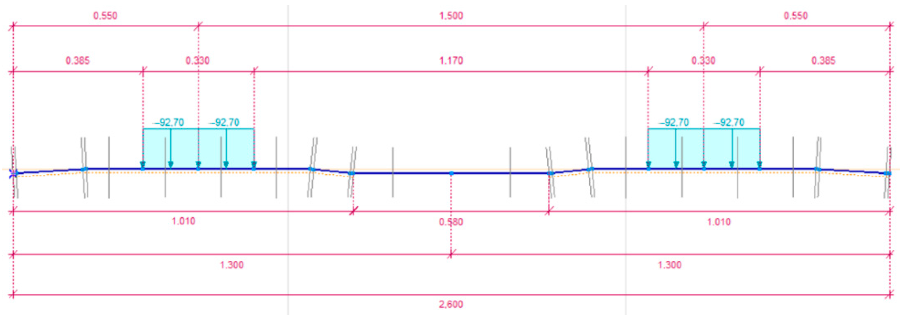
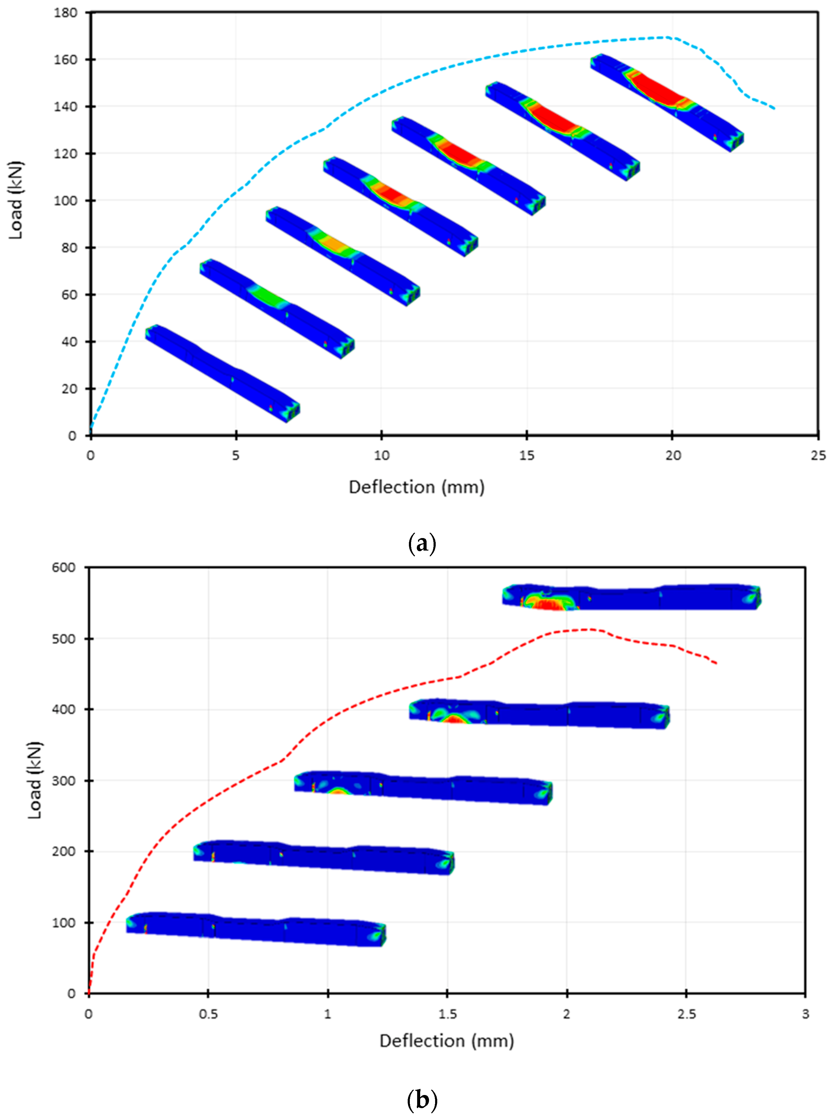
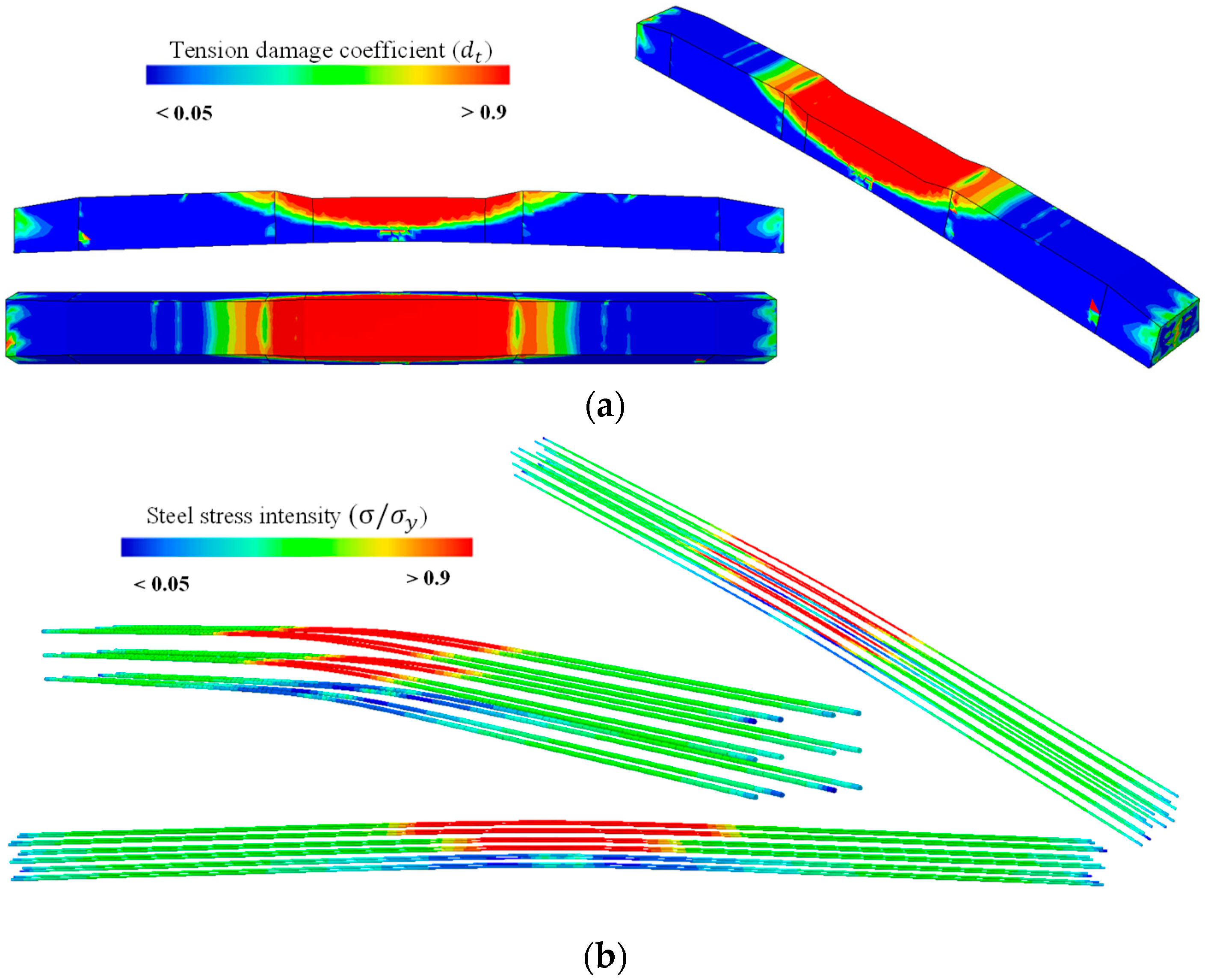
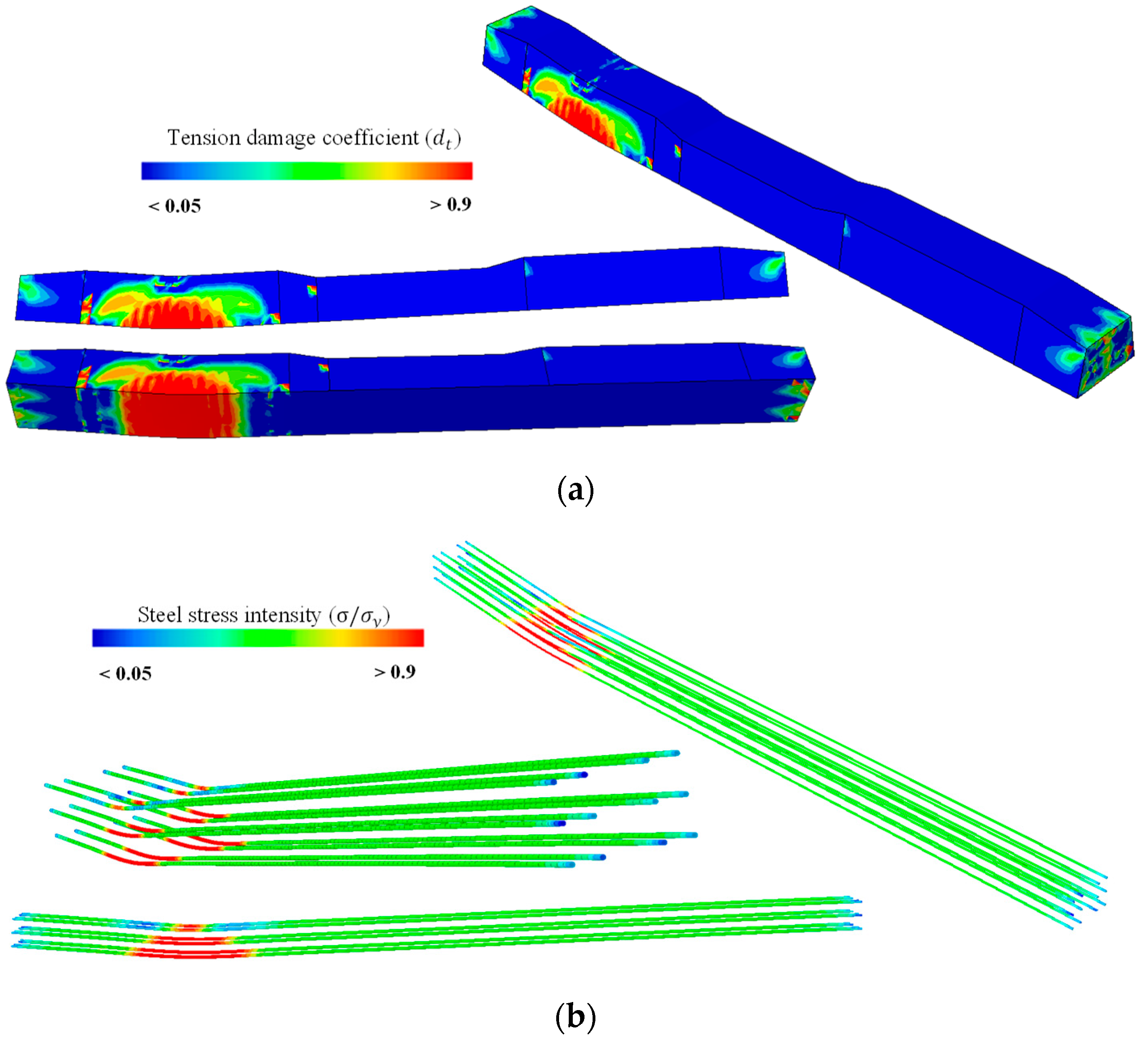
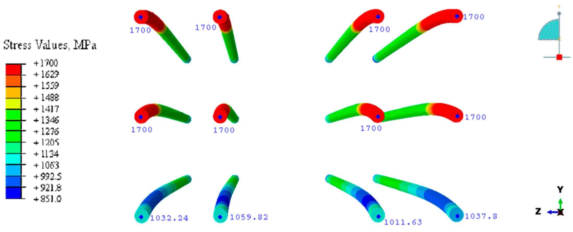
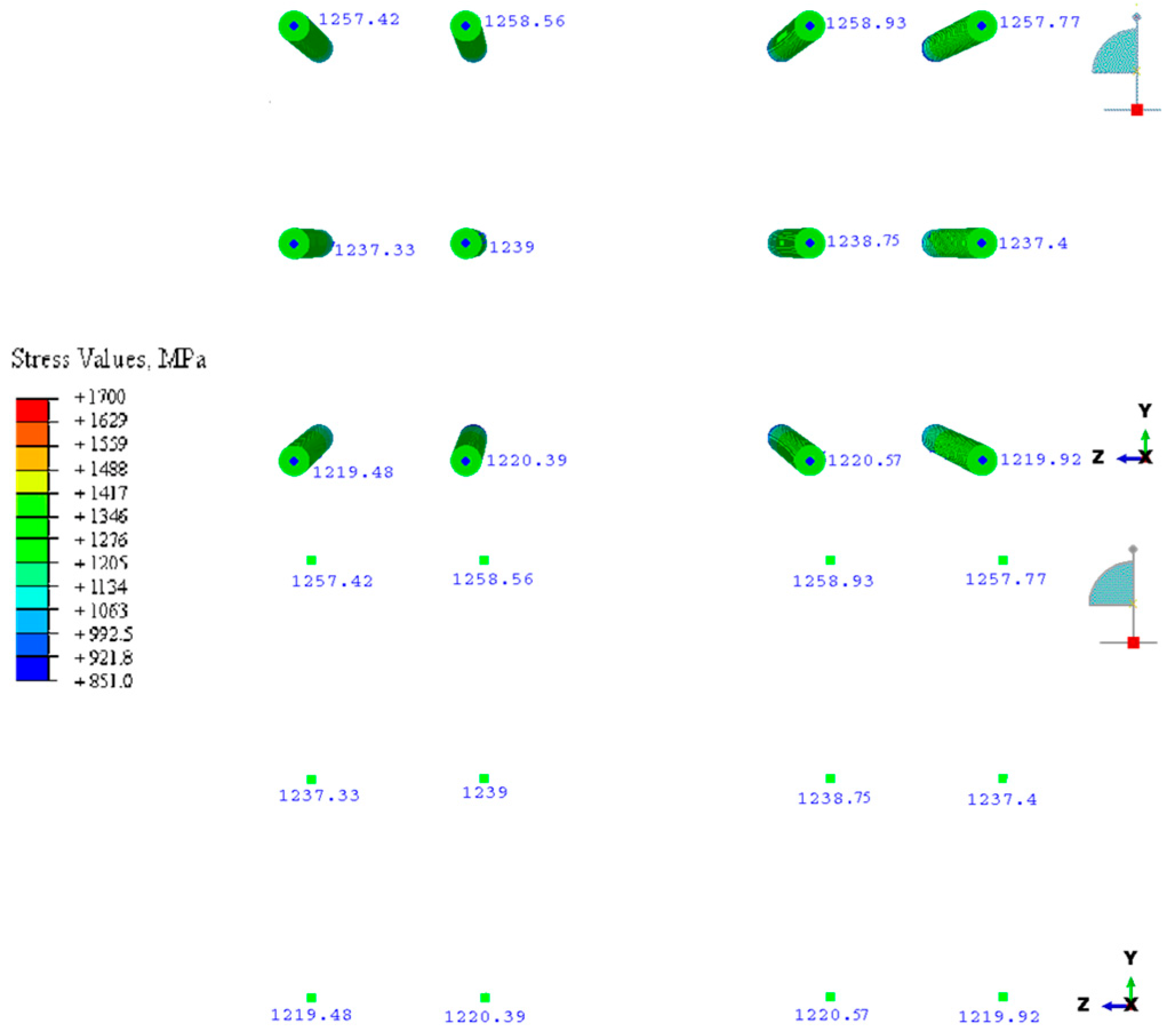
3.2. Numerical Analysis of the Designed Pre-Stressed Concrete Railway Sleepers Using ABAQUS Finite Element Software
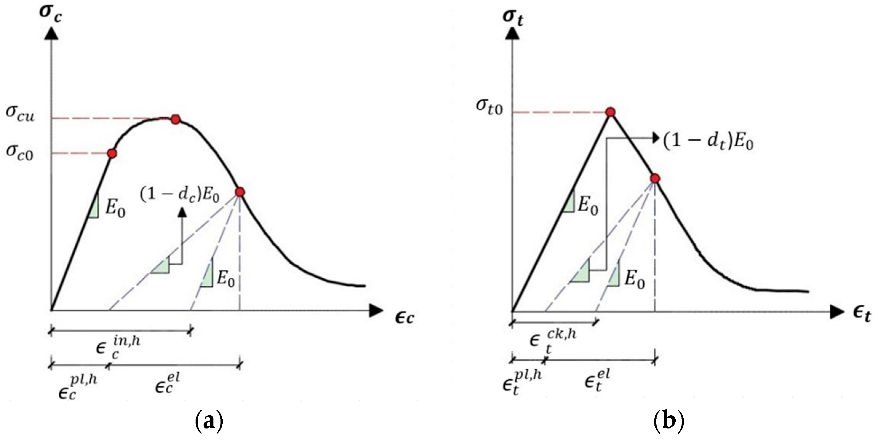
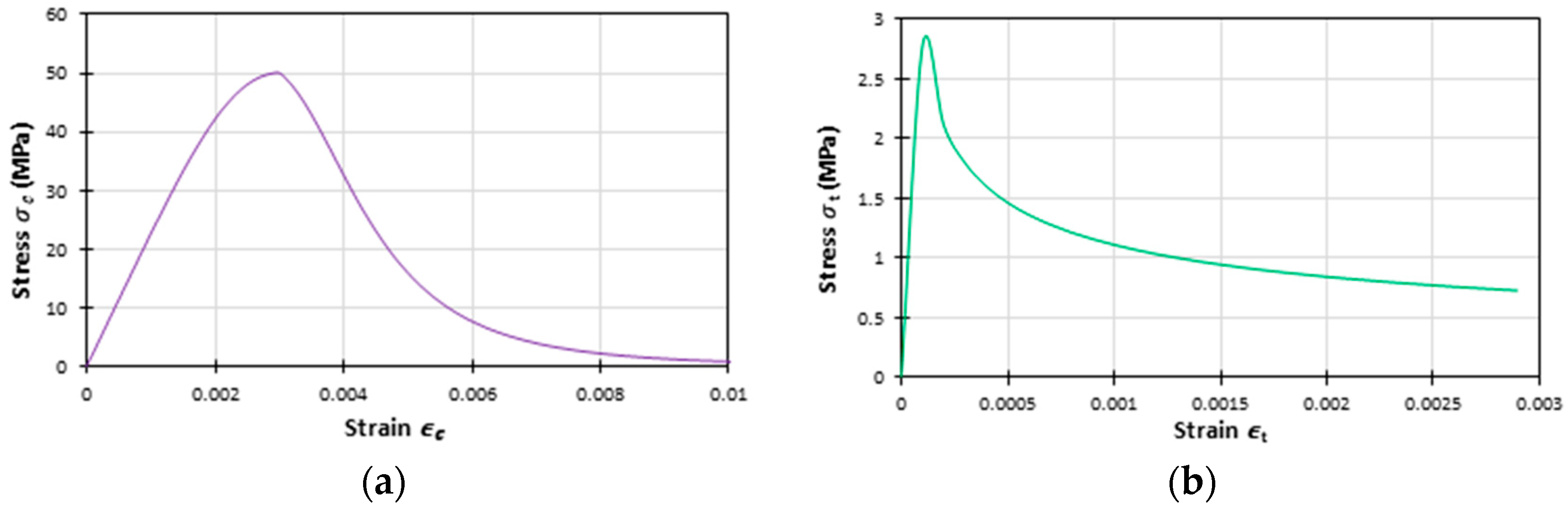
3.2.1. Concrete Damage Plasticity Constitutive Model
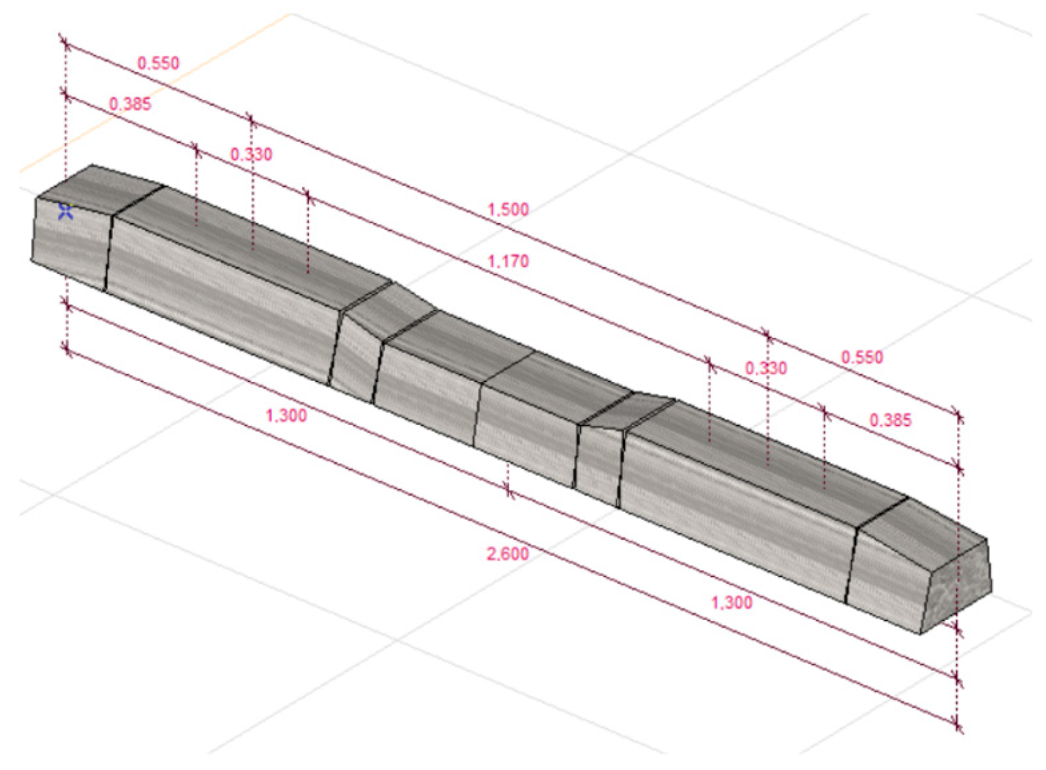
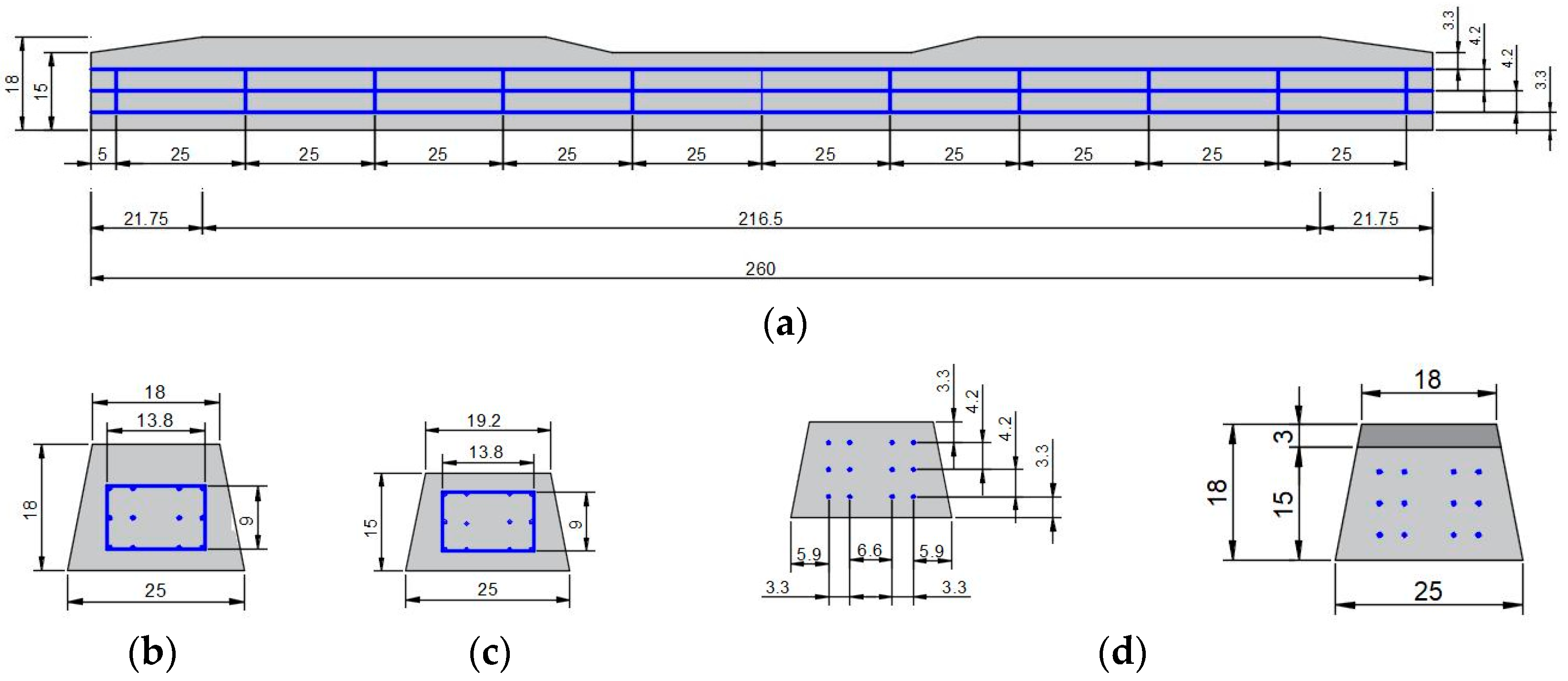
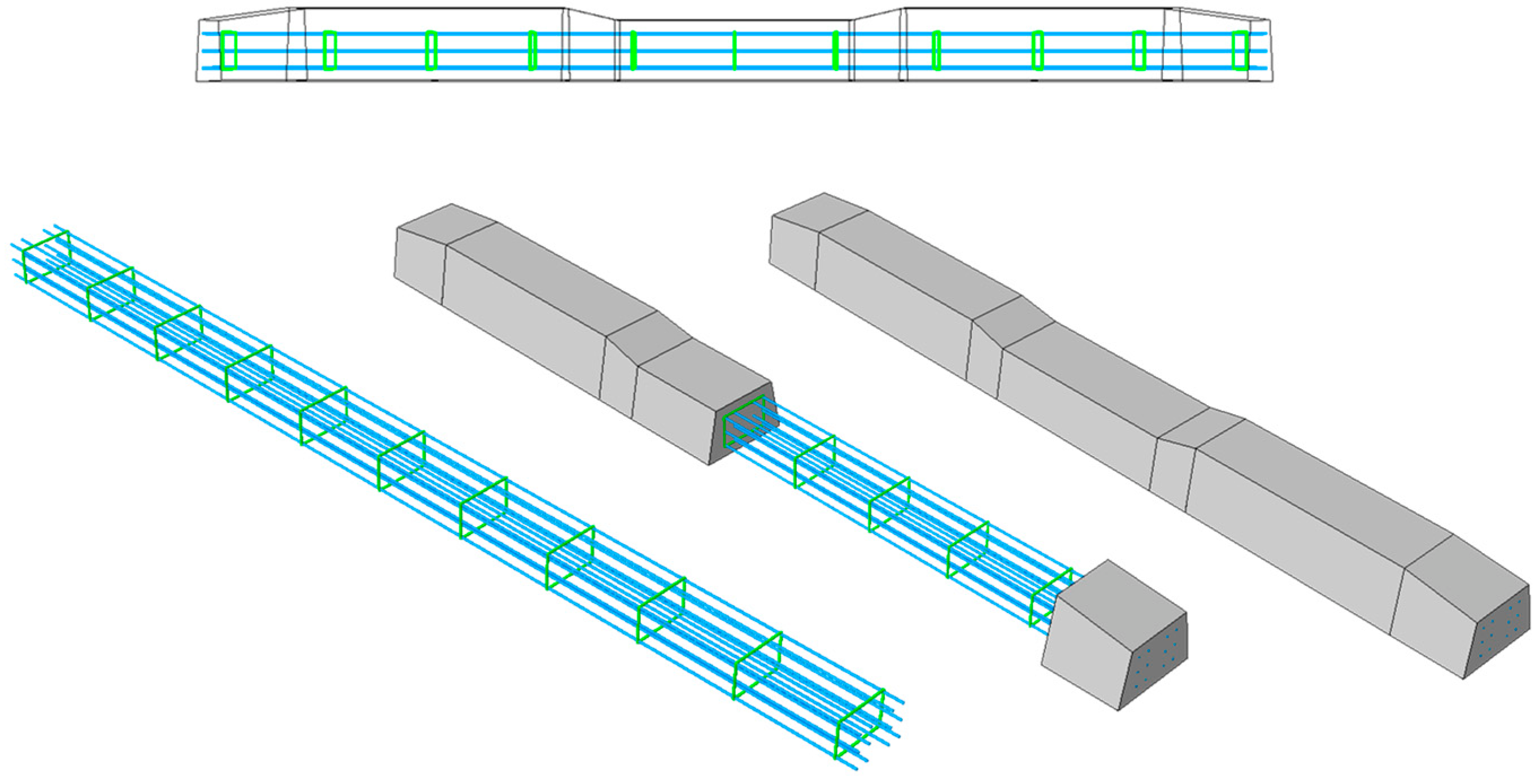
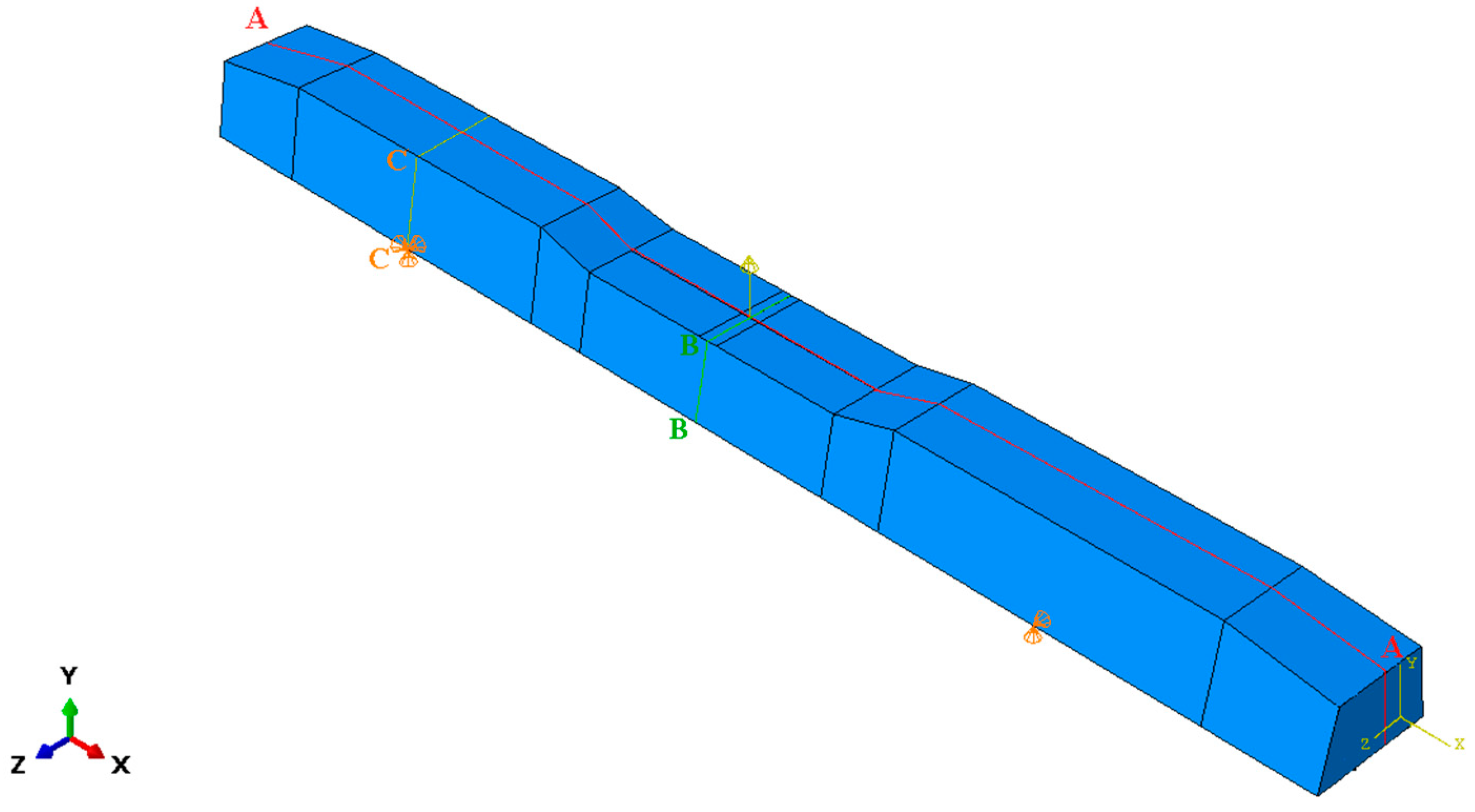
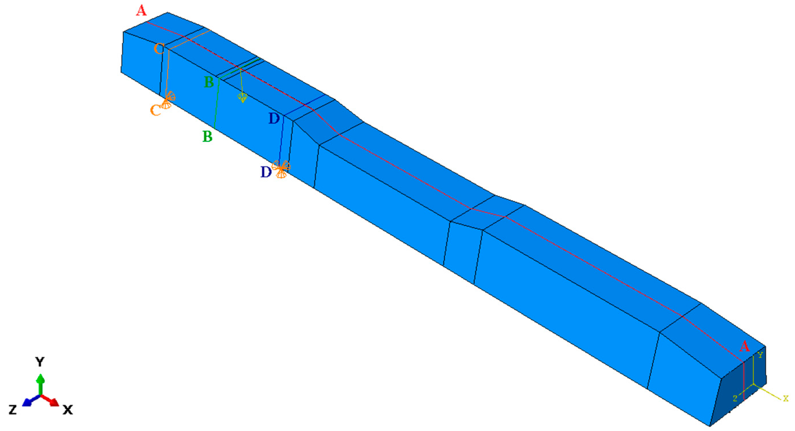
3.2.2. Details of the Pre-Stressed Sleeper
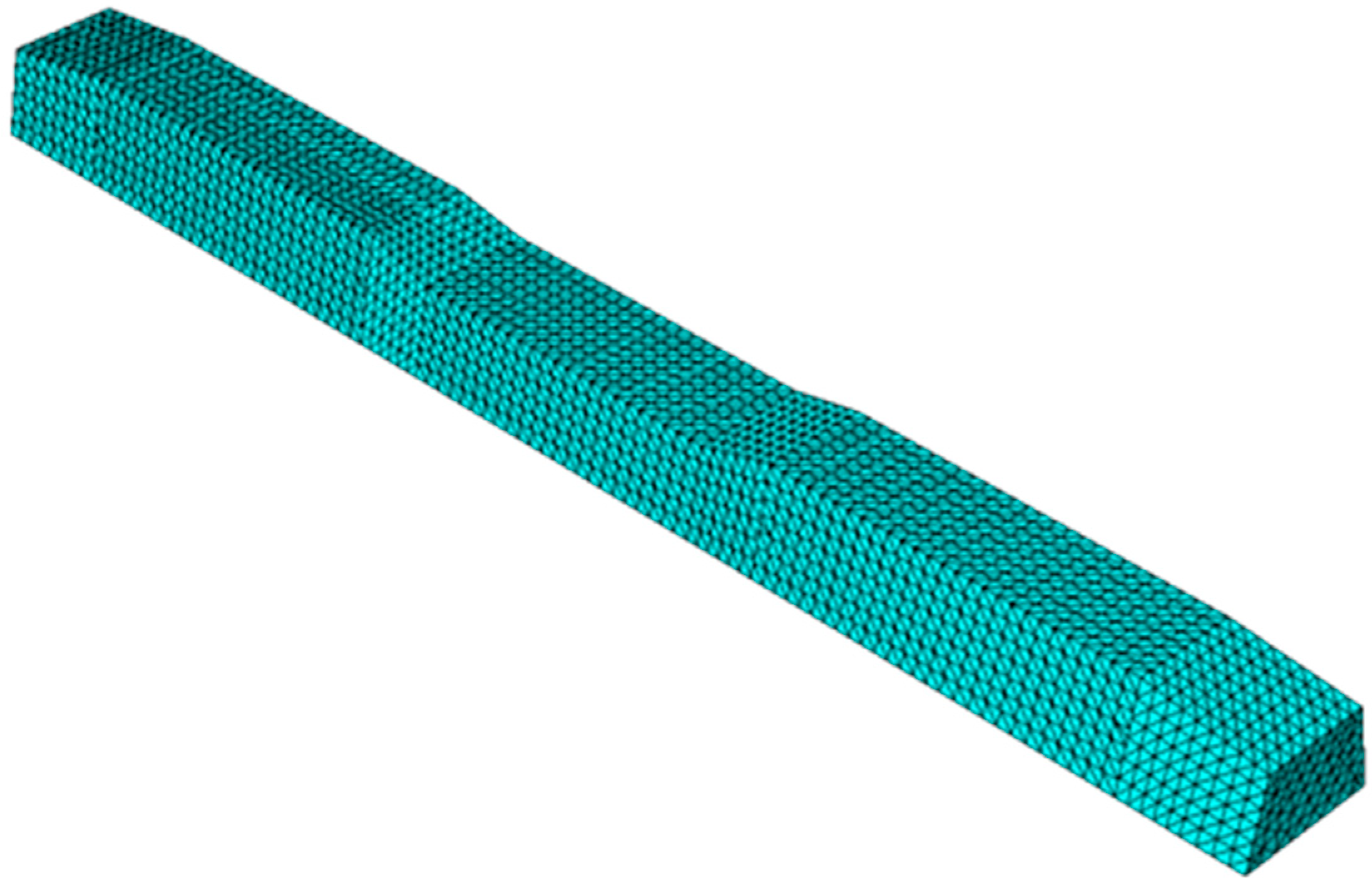
3.2.3. Numerical Modeling of the Sleeper by ABAQUS FE Software
4. Discussion
5. Conclusions
- considering real laboratory tests and validating the results from FE modeling with them;
- considering material models that allow for the calculation of crackings and their effect in the concrete, in addition to being based on measurements of real cubes and cylindrical specimens in the laboratory (compressive and splitting tensile tests);
- taking into consideration the prestressing loss more exactly instead of the approximate calculation;
- the ABAQUS model and the traditional (hand-made) calculation can be compared.
Author Contributions
Funding
Data Availability Statement
Acknowledgments
Conflicts of Interest
Abbreviations/Nomenclature
| Abbreviations | |
| 2D | two dimensions or two dimensional |
| 2.5D | two and a half dimensions or two and a half dimensional |
| 3D | three dimensions or three dimensional |
| ABAQUS | a sophisticated software based on finite element method calculation which is mainly used for research and development |
| AxisVM | a software based on finite element method calculation established in Hungary that is mainly applied for engineering design |
| CDP | Concrete Damage Plasticity |
| DE | discrete element |
| DEM | discrete element method or discrete element modeling |
| DIC | digital image correlation |
| FE | finite element |
| FEM | finite element method or finite element modeling |
| L-CFRPU | laminated carbon fiber reinforced polyurethane |
| MSFRC | macro synthetic fiber-reinforced concrete |
| POSTSRC | post-stressed reinforced concrete |
| PRESRC | pre-stressed reinforced concrete |
| RC | reinforced concrete |
| RPC | reactive powder concrete |
| SR | static risk |
| UHPC | ultra-high performance concrete |
| UHP-FRC | ultra-high performance fiber-reinforced concrete |
| USP | under sleeper pad |
| Nomenclature | |
| ν | Poisson’s ratio [−] |
| ρ | Density [kg/m3] |
| Γ | The multiply of γr and γi, introduced factor [−] |
| φ | Speed factor according to the Eisenmann equation [−] |
| Φ | Dynamic factor according to Eisenmann equation [−] |
| σ | Normal stress [MPa] or [Pa] |
| σc | Compression (compressive) stress [MPa] or [Pa] |
| σt | Tensile stress [MPa] or [Pa] |
| σy | Yield stress [MPa] or [Pa] |
| Actual internal compression force [MPa] or [Pa] | |
| Internal force tensor value [MPa] or [Pa] | |
| Actual internal force [MPa] or [Pa] | |
| Actual internal tension force [MPa] or [Pa] | |
| ∆ | Vertical deflection of the sleeper in ABAQUS modeling [mm] |
| εc | Compression strain [−] |
| εij | General strain tensor value [−] |
| εijel | Elastic part of the general strain tensor value [−] |
| εijpl | Plastic part of the general strain tensor value [−] |
| εt | Tensile strain [−] |
| Elastic strain in compression [−] | |
| Plastic strain in compression [−] | |
| Elastic strain in tension [−] | |
| Plastic strain in tension [−] | |
| A | Supporting contact area regarding one rail [mm2] |
| A1 | Shear area associated with shear forces in local 1st direction [cm2] |
| A2 | Shear area associated with shear forces in local 2nd direction [cm2] |
| Ax | Axial (cross-sectional) area [cm2] |
| Ay | Shear area in local y direction [cm2] |
| Az | Shear area in local z direction [cm2] |
| b1 | Width of sleeper bottom [mm] |
| C | Bedding modulus below the sleeper’s bottom [N/mm3] |
| d | Thickness of the sleeper under the rail foot’s center [m] |
| d’ | Scalar stiffness degradation variable [−] |
| dc | Compression damage variable [−] |
| dt | Tension damage variable [−] |
| Initial (undamaged) elastic stiffness of the material [kN/mm] | |
| Degraded elastic stiffness [kN/mm] | |
| e | Random eccentricity [m] or [mm] |
| E0 | Material initial (undamaged) Young’s modulus |
| Ex | Young’s modulus of elasticity in the local x direction [kN/cm2] |
| Ey | Young’s modulus of elasticity in the local y direction [kN/cm2] |
| f | Half of the load distribution width related to the sleeper [m] |
| fb0 | Equibiaxial compressive strength of concrete [MPa] |
| fc0 | Uniaxial compressive strength of concrete [MPa] |
| Fz | Maximal vertical forces acting onto the sleepers [kN] |
| I1 | Principal inertia about local 1st axis [cm4] |
| I2 | Principal inertia about local 2nd axis [cm4] |
| Ix | Torsional inertia [cm4] |
| Iy | Flexural inertia about local y axis [cm4] |
| iy | Radius of inertia about y axis [cm] |
| Iyz | Centrifugal inertia [cm4] |
| Iz | Flexural inertia about local z axis [cm4] |
| iz | Radius of inertia about z axis [cm] |
| Iω | Warping modulus [cm6] |
| K | Ratio of the second stress invariant on the tensile meridian in ABAQUS modeling [−] |
| Kz | Vertical spring constant for one rail [kN/m] |
| Lc | Design distance between center lines of the rail seat for the test arrangement of mid-span loading based on EN 13230-2 [62] [m] |
| Lr | Design distance between the articulated supports center lines for the test arrangement at the rail seat section based on EN 13230-2 [62] [m] |
| LS | Length of the sleeper [mm] |
| M | Mean value of bending moment [kNm] |
| Md | Design value of bending moment [kNm] |
| Mdc− | Negative extreme value of the bending moment causing cracking related to the sleeper’s center [kNm] |
| Mdc+ | Positive extreme value of the bending moment causing cracking related to the sleeper’s center [kNm] |
| Mdr− | Negative extreme value of the bending moment causing cracking under the rail foot [kNm] |
| Mdr+ | Positive extreme value of the bending moment causing cracking under the rail foot [kNm] |
| Mdc−,breakage | Negative extreme value of the bending moment causing breakage in the sleeper’s center [kNm] |
| Mdr+,breakage | Positive extreme value of the bending moment causing breakage under the rail foot [kNm] |
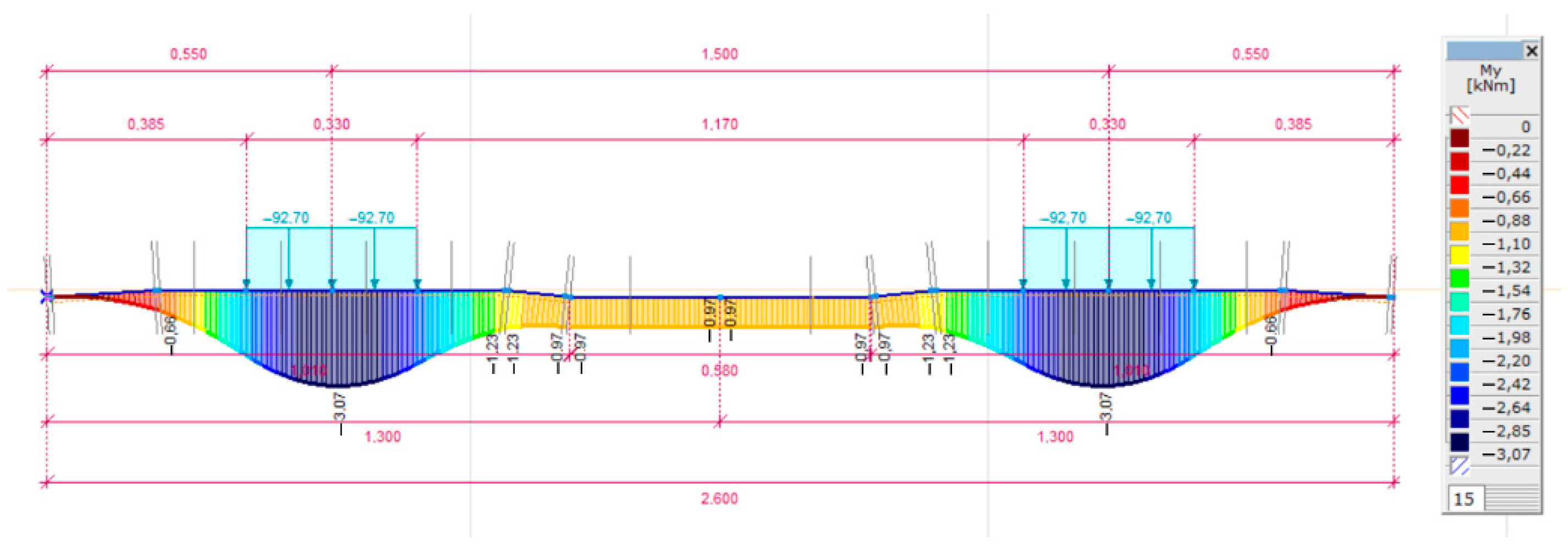
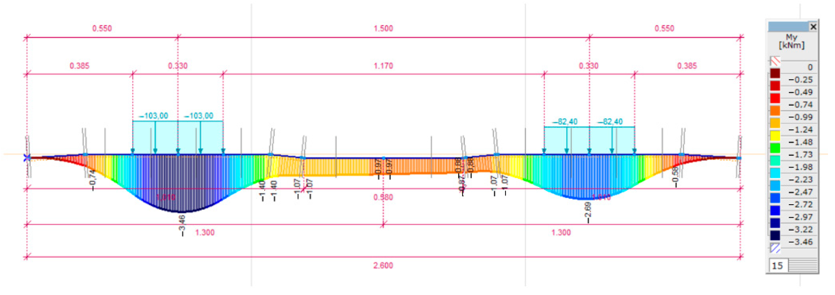
| My | Bending moment (around the y axis) [kNm] |
| n | Track condition parameter according to the Eisenmann equation [−] |
| P | Vertical load acting on the sleeper in ABAQUS modeling [kN] |
| Pi | Inner circumference (holes) [cm] |
| Po | Outer circumference (cross-section contour) [cm] |
| Qv’ | Specified maximum of the Qv [kN] |
| Qv1 | One of the vertical wheel forces in a wheelset [kN] |
| qv1 | Vertical force acting on the one rail [kN] |
| Qv2 | The other vertical wheel force in the same wheelset [kN] |
| qv2 | Vertical force acting on the other rail [kN] |
| qz | Linear distributed vertical forces acting onto the sleepers [kN] |
| r | Distance between rail centers, its nominal value is 1.5 m if there is a standard track gauge (1.435 m) |
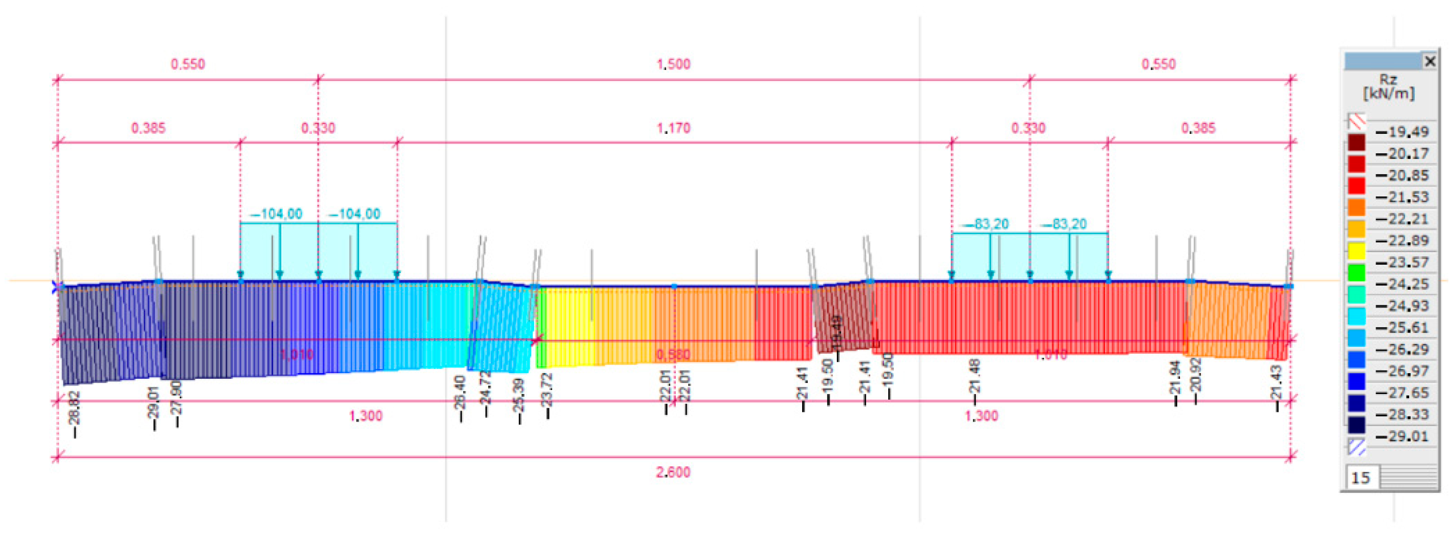
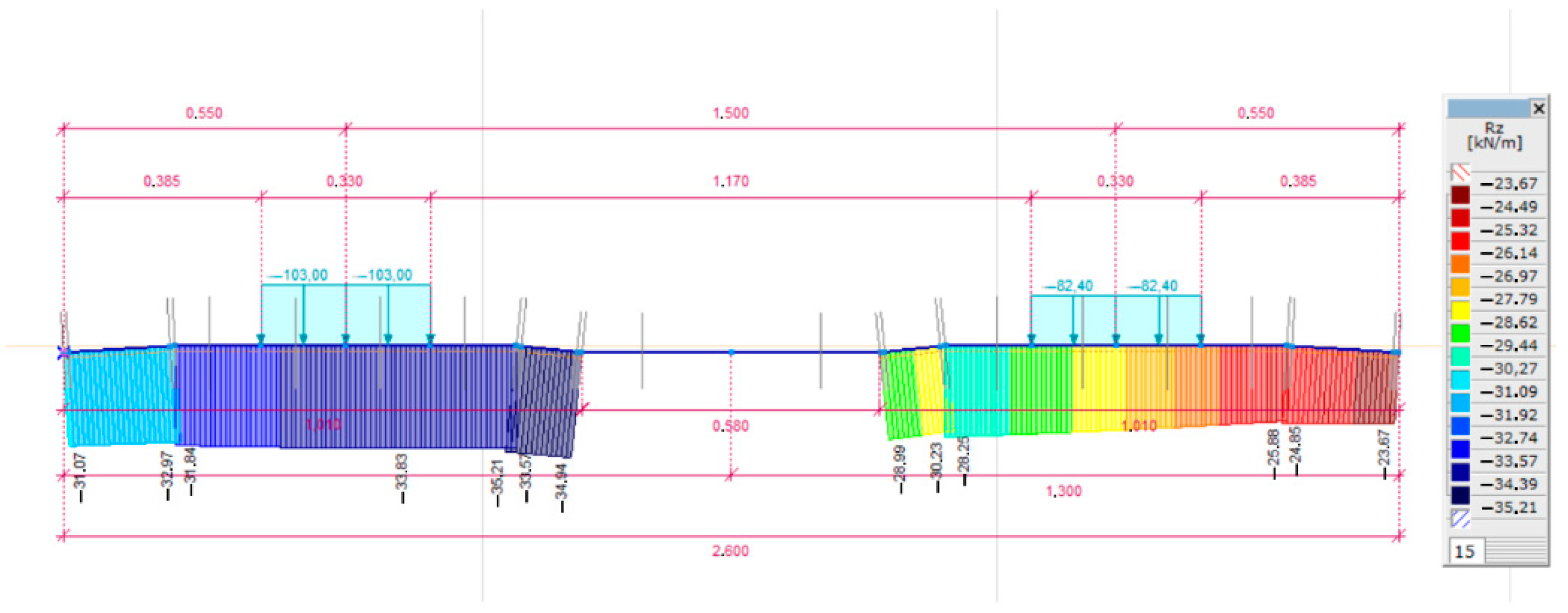
| Rz | Line support force of the sleeper [kN/m] |
| s | Width of the rail foot [m] |
| t | Student distribution parameter according to the Eisenmann equation [−] |
| tR | Distance between the track rail axes [mm] |
| V | Allowed speed on the track [km/h] |
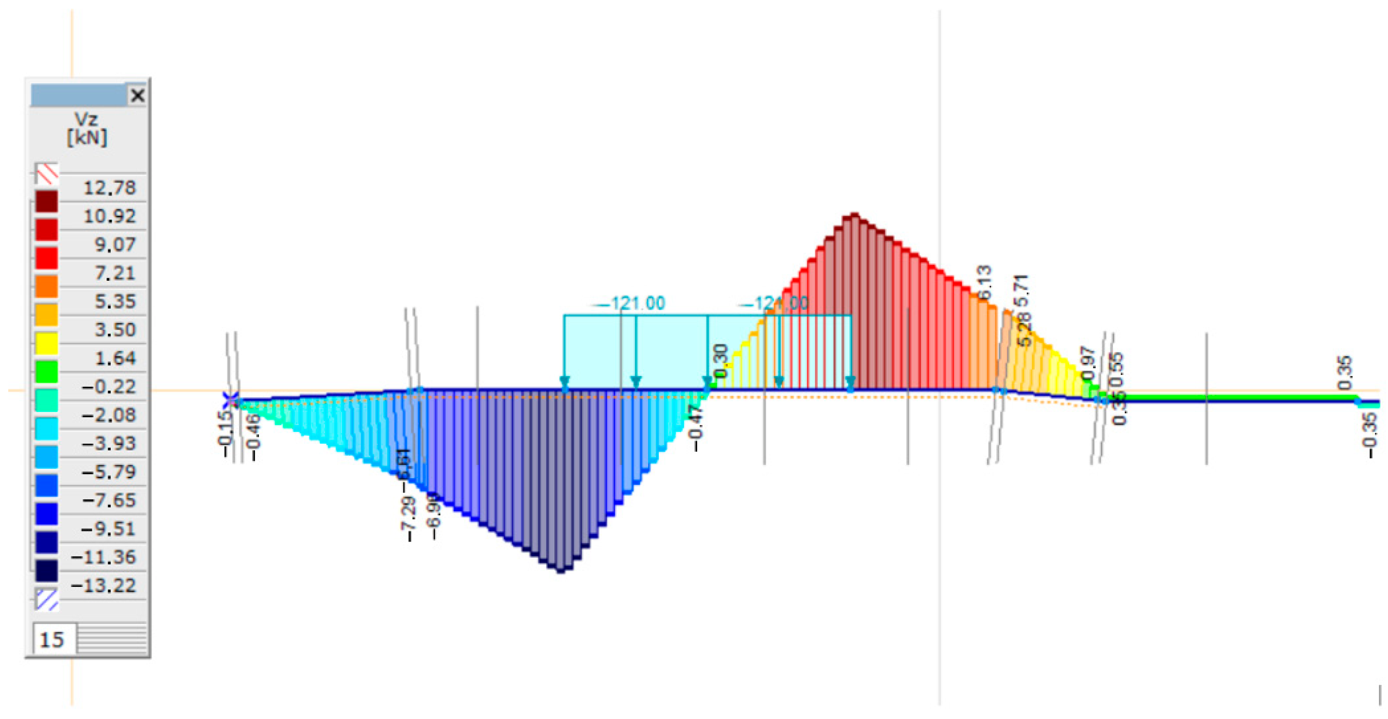
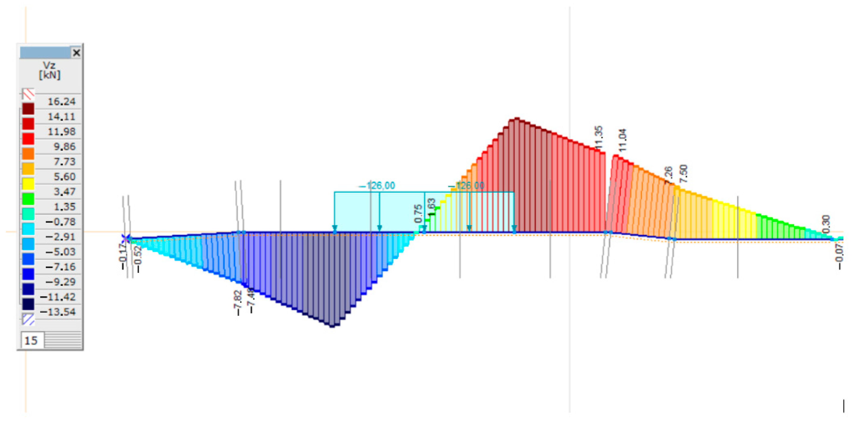
| Vz | Shear force of the sleeper [kN] |
| Vz,Ed | Design value of the shear force of the sleeper [kN] |
| Wy,el,b | Elastic cross-section modulus, regarding to y axis, bottom [cm3] |
| Wy,el,t | Elastic cross-section modulus, regarding to y axis, top [cm3] |
| Wy,pl | Plastic cross-section modulus regarding to y axis [cm3] |
| Wz,el,b | Elastic cross-section modulus, regarding to z axis, bottom [cm3] |
| Wz,el,t | Elastic cross-section modulus regarding the z axis, top [cm3] |
| Wz,pl | Plastic cross-section modulus regarding the z axis [cm3] |
| yG * | Position of the center of gravity of the cross-section in local y direction relative to the lower-left corner of the circumscribed rectangle [cm] |
| ys | Position of the shear center in local y directions relative to the center of gravity [cm] |
| zG * | Position of the center of gravity of the cross-section in local z direction relative to the lower-left corner of the circumscribed rectangle [cm] |
| zs | Position of the shear center in local z directions relative to the center of gravity [cm] |
| αT | Linear thermal expansion ratio [1/°C] |
| γd | Safety factor due to the load distribution [−] |
| γi | Safety factor due to the support faults [−] |
| γp | Safety factor due to the damping effect of the rail pad [−] |
| γr | Safety factor due to the geometrical faults [−] |
| γV | Safety factor due to the speed [−] |
| α | Angle between local 1st axis and the local y axis [°] |
| ρ1 | Shear factor for local 1st direction [−] |
| ρ2 | Shear factor for local 2nd direction [−] |
| ρy | Shear factor in local y direction [−] |
| ρyz | Shear factor for local y–z cross [−] |
| ρz | Shear factor in local y direction [−] |
References
- Geurs, K.T.; Van Wee, B. Accessibility evaluation of land-use and transport strategies: Review and research directions. J. Transp. Geogr. 2004, 12, 127–140. [Google Scholar] [CrossRef]
- Limao, N.; Venables, A.J. Infrastructure, geographical disadvantage, transport costs, and trade. World Bank Econ. Rev. 2001, 15, 451–479. [Google Scholar] [CrossRef] [Green Version]
- Ramazan, B.; Mussaliyeva, R.; Bitileuova, Z.; Naumov, V.; Taran, I. Choosing the logistics chain structure for deliveries of bulk loads: Case study of the Republic Kazakhstan. Natl. Hirnychyi Univ. Nauk. Visnyk 2021, 3, 142–147. [Google Scholar] [CrossRef]
- Nugymanova, G.; Nurgaliyeva, M.; Zhanbirov, Z.; Naumov, V.; Taran, I. Choosing a servicing company’s strategy while interacting with freight owners at the road transport market. Sci. Bull. Natl. Min. Univ. 2021, 1, 204–210. [Google Scholar] [CrossRef]
- Macura, D.; Laketić, M.; Pamučar, D.; Marinković, D. Risk Analysis Model with Interval Type-2 Fuzzy FMEA—Case Study of Railway Infrastructure Projects in the Republic of Serbia. Acta Polytech. Hung. 2022, 19, 103–118. [Google Scholar] [CrossRef]
- Fischer, S.; Kocsis Szürke, S. Detection Process of Energy Loss in Electric Railway Vehicles. Facta Univ. Ser. Mech. Eng. 2023, 11368. [Google Scholar] [CrossRef]
- Fischer, S. Traction Energy Consumption of Electric Locomotives and Electric Multiple Units at Speed Restrictions. Acta Tech. Jaurinensis 2015, 8, 240–256. [Google Scholar] [CrossRef] [Green Version]
- Fischer, S.; Harangozó, D.; Németh, D.; Kocsis, B.; Sysyn, M.; Kurhan, D.; Brautigam, A. Investigation of Heat-Affected Zones of Thermite Rail Weldings. Facta Univ. Ser. Mech. Eng. 2023. [Google Scholar] [CrossRef]
- Kuchak, A.; Marinkovic, D.; Zehn, M. Parametric Investigation of a Rail Damper Design Based on a Lab-Scaled Model. J. Vib. Eng. Technol. 2021, 9, 51–60. [Google Scholar] [CrossRef]
- Kuchak, A.; Marinkovic, D.; Zehn, M. Finite Element Model Updating—Case Study of a Rail Damper. Struct. Eng. Mech. Int. J. 2020, 73, 27–35. [Google Scholar] [CrossRef]
- Fischer, S. Geogrid reinforcement of ballasted railway superstructure for stabilization of the railway track geometry—A case study. Geotext. Geomembr. 2022, 50, 1036–1051. [Google Scholar] [CrossRef]
- Sysyn, M.; Nabochenko, O.; Kovalchuk, V.; Przybyłowicz, M.; Fischer, S. Investigation of Interlocking Effect of Crushed Stone Ballast during Dynamic Loading. Rep. Mech. Eng. 2021, 2, 65–76. [Google Scholar] [CrossRef]
- Fischer, S.; Eller, B.; Kada, Z.; Németh, A. Railway Construction; Universitas-Győr Nonprofit Kft.: Győr, Hungary, 2015. [Google Scholar]
- Siahkouhi, M.; Li, X.; Han, X.; Kaewunruen, S.; Jing, G. Experimental and finite element assessments of the fastening system of fiber-reinforced foamed urethane (FFU) composite sleepers. Eng. Fail. Anal. 2022, 141, 106693. [Google Scholar] [CrossRef]
- Liu, C.; Hunag, X.; Wu, Y.Y.; Deng, X.; Zheng, Z.; Yang, B. Studies on mechanical properties and durability of steel fiber reinforced concrete incorporating graphene oxide. Cem. Concr. Compos. 2022, 130, 104508. [Google Scholar] [CrossRef]
- Çeçen, F.; Aktaş, B.; Öztürk, H.; Öztürk, İ.Ş.; Navdar, M.B. Comparative modal analysis of B70 and LCR-6 type railway sleepers after repeated impact loads. Constr. Build. Mater. 2022, 336, 127563. [Google Scholar] [CrossRef]
- Çeçen, F.; Aktaş, B.; Öztürk, H.; Öztürk, İ.Ş.; Navdar, M.B. Comparison of new LCR and ordinary prestressed concrete railway sleepers with LUR tests. Constr. Build. Mater. 2022, 321, 126414. [Google Scholar] [CrossRef]
- Çeçen, F.; Aktaş, B.; Öztürk, H.; Navdar, M.B.; Öztürk, İ.Ş. Behaviour of new LCR and ordinary prestressed concrete railway sleepers under repeated impact loads. Constr. Build. Mater. 2022, 319, 126151. [Google Scholar] [CrossRef]
- Aktaş, B.; Çeçen, F.; Öztürk, H.; Navdar, M.B.; Öztürk, İ.Ş. Comparison of prestressed concrete railway sleepers and new LCR concrete sleepers with experimental modal analysis. Eng. Fail. Anal. 2022, 131, 105821. [Google Scholar] [CrossRef]
- Çeçen, F.; Aktaş, B. Incremental LUR tests of new LCR concrete railway sleepers. Eng. Fail. Anal. 2021, 130, 105793. [Google Scholar] [CrossRef]
- Ahmed, S.; Atef, H.; Husain, M. Improvement of mechanical properties of railway track concrete sleepers using ultra high performance concrete (UHPC). Frat. E Integrita Strutt. 2022, 60, 243–264. [Google Scholar] [CrossRef]
- Shakeri, A.; Remennikov, A.M.; Sheikh, M.N. Development of fibre-reinforced concrete mix for manufacturing non-prestressed concrete sleepers. Structures 2022, 37, 588–599. [Google Scholar] [CrossRef]
- Jing, G.; Yunchang, D.; You, R.; Siahkouhi, M. Comparison study of crack propagation in rubberized and conventional prestressed concrete sleepers using digital image correlation. Proc. Inst. Mech. Eng. Part F J. Rail Rapid Transit 2021, 236, 350–361. [Google Scholar] [CrossRef]
- Camille, C.; Hewage, D.K.; Mirza, O.; Clarke, T. Full-scale static and single impact testing of prestressed concrete sleepers reinforced with macro synthetic fibres. Transp. Eng. 2022, 7, 100104. [Google Scholar] [CrossRef]
- Kumar, M.H.; Rangappa, S.M.; Siengchin, S. A Comprehensive Review on Metal Matrix Composites for Railway Applications. Appl. Sci. Eng. Prog. 2022, 15, 5790. [Google Scholar] [CrossRef]
- Wang, J.; Siahkouhi, M.; Astaraki, F.; Uuganbayar, S.; Jing, G.; Movahedi Rad, M. Modification of Concrete Railway Sleeper Mix Design, Using a Hybrid Application of Steel Fibers. Acta Polytech. Hung. 2022, 19, 119–130. [Google Scholar] [CrossRef]
- Sulaiman, N.A.; Adnan, S.H.; Izaan, A.H.; Osman, M.H.; Jeni, M.L.A.; Jusoh, W.A.W.; Jamellodin, Z.; Hamid, N.A.A.; Salleh, N. The Sound Absorption Coefficient of Railway Concrete Sleepers Containing Palm Oil Fuel Ash (POFA) As a Cement Replacement Material. J. Phys. Conf. Ser. 2021, 2129, 012032. [Google Scholar] [CrossRef]
- Esmaeili, M.; Amiri, H. Laboratory Investigation into the Flexural Behavior of Embedded Concrete Sleepers in Two-Stage Concrete with Preplaced Ballast Aggregate. Int. J. Concr. Struct. Mater. 2022, 16, 12. [Google Scholar] [CrossRef]
- Watanabe, T.; Goto, K.; Matsuoka, K.; Minoura, S. Verification of Longitudinal Level Irregularity Suppression Effect at the Structural Boundary by Ballasted Ladder Track. Appl. Sci. 2022, 12, 4150. [Google Scholar] [CrossRef]
- Li, D.; Kaewunruen, S.; You, R.; Liu, P. Fatigue life modelling of railway prestressed concrete sleepers. Structures 2022, 41, 643–656. [Google Scholar] [CrossRef]
- Dung, T.A.; Tham, M.V. Numerical Simulation in the Assessment Fatigue Life of Prestressed Concrete Sleeper on the Urban Railway. Lect. Notes Civ. Eng. 2022, 203, 421–430. [Google Scholar] [CrossRef]
- César Bastos, J.; Dersch, M.S.; Edwards, J.R. Degradation Mechanisms of Concrete Due to Water Flow in Cracks of Prestressed Railroad Sleepers under Cyclic Loading. J. Mater. Civ. Eng. 2022, 34, 04022025. [Google Scholar] [CrossRef]
- Wang, M.; Han, X.; Jing, G.; Wang, H. Experimental and numerical analysis on mechanical behaviour of steel turnout sleeper. Constr. Build. Mater. 2022, 329, 127133. [Google Scholar] [CrossRef]
- Koyama, E.; Ito, K.; Hayano, K.; Momoya, Y. A new approach for evaluating lateral resistance of railway ballast associated with extended sleeper spacing. Soils Found. 2021, 61, 1565–1580. [Google Scholar] [CrossRef]
- Nobakht, S.; Zakeri, J.A.; Safizadeh, A. Investigation on longitudinal resistance of the ballasted railway track under vertical load. Constr. Build. Mater. 2022, 317, 126074. [Google Scholar] [CrossRef]
- Salih, C.; Manalo, A.; Ferdous, W.; Yu, P.; Heyer, T.; Schubel, P. Behaviour of timber-alternative railway sleeper materials under five-point bending. Constr. Build. Mater. 2022, 316, 125882. [Google Scholar] [CrossRef]
- Másmela, C.; Teixeira, E.; Tinoco, J.; Matos, J.C.E.; Mateus, R. Viability Study of the Application of Bi-Block Concrete Sleepers as a Solution for Technical Landfills. Appl. Sci. 2022, 12, 3065. [Google Scholar] [CrossRef]
- Li, D.; You, R.; Kaewunruen, S. Crack Propagation Assessment of Time-Dependent Concrete Degradation of Prestressed Concrete Sleepers. Sustainability 2022, 14, 3217. [Google Scholar] [CrossRef]
- Idczak, W.; Lewandrowski, T.; Pokropski, D.; Rudnicki, T.; Trzmiel, J. Dynamic Impact of a Rail Vehicle on a Rail Infrastructure with Particular Focus on the Phenomenon of Threshold Effect. Energies 2022, 15, 2119. [Google Scholar] [CrossRef]
- Sañudo, R.; Jardí, I.; Martínez, J.C.; Sánchez, F.J.; Miranda, M.; Alonso, B.; dell’Olio, L.; Moura, J.L. Monitoring Track Transition Zones in Railways. Sensors 2021, 22, 76. [Google Scholar] [CrossRef]
- Kaewunruen, S.; Fu, H.; Ye, C. Numerical studies to evaluate crack propagation behaviour of prestressed concrete railway sleepers. Eng. Fail. Anal. 2022, 131, 105888. [Google Scholar] [CrossRef]
- Momoya, Y.; Ito, K.; Kikkawa, S. Settlement of Ballasted Track with Large Sleeper Spacing. Lect. Notes Civ. Eng. 2022, 165, 77–86. [Google Scholar] [CrossRef]
- You, R.; Wang, J.; Kaewunruen, S.; Wang, M.; Ning, N. Comparative Investigations into Environment-Friendly Production Methods for Railway Prestressed Concrete Sleepers and Bearers. Sustainability 2022, 14, 1059. [Google Scholar] [CrossRef]
- Markulik, Š.; Petrík, J.; Šolc, M.; Blaško, P.; Palfy, P.; Sütőová, A.; Girmanová, L. Analysis of Fault Conditions in the Production of Prestressed Concrete Sleepers. Appl. Sci. 2022, 12, 928. [Google Scholar] [CrossRef]
- Du, W.; Deng, S.J.; Ren, J.J.; Zhao, Z.M.; Wei, Z.; Zhang, K.Y.; Ye, W.L. Debonding Analysis and Identification of the Interface between Sleeper and Track Slab for Twin-Block Slab Tracks. Int. J. Struct. Stab. Dyn. 2021, 21, 2140011. [Google Scholar] [CrossRef]
- Gondhalekar, T.M.; Panigrahi, S.K. Transient Analysis of Railway Sleeper using Three-Dimensional Finite Element Method. J. Inst. Eng. India Ser. A 2021, 102, 1113–1128. [Google Scholar] [CrossRef]
- El–sayed, H.M.; Zohny, H.N.; Riad, H.S.; Fayed, M.N. Structural response of monoblock railway concrete sleepers and fastening systems subject to coupling vertical and lateral loads: A numerical study. Structures 2021, 34, 995–1007. [Google Scholar] [CrossRef]
- Kurhan, M.; Kurhan, D.; Brazhnyk, M.; Kovalskyi, D. Features of stress-strain state of the dual railway gauge. Sci. Transp. Prog. 2019, 1, 51–63. [Google Scholar] [CrossRef]
- Kurhan, D.; Kurhan, M. Modeling the Dynamic Response of Railway Track. IOP Conf. Ser. Mater. Sci. Eng. 2019, 708, 012013. [Google Scholar] [CrossRef]
- Kurhan, D.; Fischer, S. Modeling of the Dynamic Rail Deflection using Elastic Wave Propagation. J. Appl. Comput. Mech. 2022, 8, 379–387. [Google Scholar] [CrossRef]
- Woodward, P.K.; Brennan, A.; Laghrouche, O.; Esen, A.; Connolly, D.; Mariot, T. Geotechnical Centrifuge and Full-Scale Laboratory Testing for Performance Evaluation of Conventional and High-Speed Railway Track Structures. Lect. Notes Civ. Eng. 2022, 165, 957–968. [Google Scholar] [CrossRef]
- Landgraf, M.; Zeiner, M.; Knabl, D.; Corman, F. Environmental impacts and associated costs of railway turnouts based on Austrian data. Transp. Res. Part D Transp. Environ. 2022, 103, 103168. [Google Scholar] [CrossRef]
- de Souza Lima, E.H.; Carneiro, A.M.P. A Review of Failures of Railway Monoblock Prestressed Concrete Sleepers. Eng. Fail. Anal. 2022, 137, 106389. [Google Scholar] [CrossRef]
- Li, X.; Doh, S.I.; Jing, G.; Chong, B.W.; Suil, A.L.; Chin, S.C. A comparative review on American, European and Chinese standard for railway concrete sleeper. Phys. Chem. Earth Parts A B C 2021, 124, 103073. [Google Scholar] [CrossRef]
- Bihary, K.; Kutasy, L.; Erdős, L.; Szikszay, G.; Csutor, J.; Lengyel, J. Vasúti Betonaljak (Concrete Railway Sleepers, In Hungarian); Műszaki Könyvkiadó: Budapest, Hungary, 1965. [Google Scholar]
- Beluzsár, J. LW-60, a nagysebességű vasúti pályák betonalja (LW-60, the concrete sleepers of high-speed railways, in Hungarian). Vasbetonépítés 1999, 1, 100–105. [Google Scholar]
- Fischer, R. Feszített betonaljak az ÖBB hálózatán (Tensioned concrete sleepers on the network of Austrian Railways, in Hungarian). Innorail Mag. 2015, 2, 26–29. [Google Scholar]
- Kormos, G.; Lógó, J.; Pintyőke, G. Betonaljak új modellezése (New modeling of concrete sleepers, in Hungarian). Innorail Mag. 2015, 2, 30–36. [Google Scholar]
- UIC 713; Design of Monoblock Concrete Sleepers. International Union of Railways (UIC): Paris, France, 2004.
- Jankó, L. Vasbeton Hídszerkezetek I-II. Műegyetemi Nyomda: Budapest, Hungary, 1998. Available online: https://antikva.hu/epiteszet/vasbeton-hidszerkezetek-i-ii-kotet/janko-laszlo (accessed on 9 February 2023).
- Csellár, Ö.; Kálmán, T.; Dulácska, E. Statikusok Könyve; Műszaki Könyvkiadó: Budapest, Hungary, 1974; Available online: https://www.antikvarium.hu/konyv/dr-csellar-odon-karman-tamas-statikusok-konyve-28766-0 (accessed on 9 February 2023).
- EN 1991-2:2003/AC:2010; Actions on Structures—Part 2: Traffic Loads on Bridges. European Committee for Standardization (CEN): Brussels, Belgium, 2006.
- Freudenstein, S.; Geisler, K.; Mölter, T.; Mißler, M.; Stolz, C. BetonKalender—Ballastless Track; Wilhelm Ernst & Sohn Verlag: Berlin, Germany, 2018. [Google Scholar]
- EN 13230-1:2006; Railway Applications—Track—Concrete Sleepers and Bearers General Requirements. European Committee for Standardization (CEN): Brussels, Belgium, 2006.
- EN 13230-2:2016; Railway Applications—Track—Concrete Sleepers and Bearers Prestressed Monoblock Sleepers. European Committee for Standardization (CEN): Brussels, Belgium, 2016.
- Liu, J.; Sysyn, M.; Liu, Z.; Kou, L.; Wang, P. Studying the Strengthening Effect of Railway Ballast in the Direct Shear Test due to Insertion of Middle-size Ballast Particles. J. Appl. Comput. Mech. 2022, 8, 1387–1397. [Google Scholar] [CrossRef]
- Strzalka, C.; Marinkovic, D.; Zehn, M.W. Stress mode superposition for a priori detection of highly stressed areas: Mode normalisation and loading influence. J. Appl. Comput. Mech. 2021, 7, 1698–1709. [Google Scholar] [CrossRef]
- Szalai, S.; Kocsis Szürke, S.; Harangozó, D.; Fischer, S. Investigation of Deformations of a Lithium Polymer Cell Using the Digital Image Correlation Method (DICM). Rep. Mech. Eng. 2022, 3, 206–224. [Google Scholar] [CrossRef]
- Kocsis Szürke, S.; Dineva, A.; Szalai, S.; Lakatos, I. Determination of Critical Deformation Regions of a Lithium Polymer Battery by DIC Measurement and WOWA Filter. Acta Polytech. Hung. 2022, 19, 113–134. [Google Scholar] [CrossRef]
- Szalai, S.; Dogossy, G. Speckle pattern optimization for DIC technologies. Acta Tech. Jaurinensis 2021, 14, 228–243. [Google Scholar] [CrossRef]
- Szalai, S.; Eller, B.; Juhász, E.; Movahedi, R.M.; Németh, A.; Harrach, D.; Baranyai, G.; Fischer, S. Investigation of Deformations of Ballasted Railway Track during Collapse Using the Digital Image Correlation Method (DICM). Rep. Mech. Eng. 2022, 3, 258–282. [Google Scholar] [CrossRef]
- Szalai, S.; Fehér, V.; Kurhan, D.; Németh, A.; Sysyn, M.; Fischer, S. Optimization of Surface Cleaning and Painting Methods for DIC Measurements on Automotive and Railway Aluminum Materials. Infrastructures 2023, 8, 27. [Google Scholar] [CrossRef]
- Szalai, S.; Szívós, B.F.; Kurhan, D.; Németh, A.; Sysyn, M.; Fischer, S. Optimization of surface preparation and painting processes for railway and automotive steel sheets. Infrastructures 2023, 8, 28. [Google Scholar] [CrossRef]
- Szalai, S.; Csótár, H.; Kurhan, D.; Németh, A.; Sysyn, M.; Fischer, S. Testing of lubricants for DIC tests to measure the forming limit diagrams of aluminum thin sheet materials. Infrastructures 2023, 8, 32. [Google Scholar] [CrossRef]
- Szalai, S.; Bálint, H.; Kurhan, D.; Németh, A.; Sysyn, M.; Fischer, S. Optimization of 3D printed rapid prototype deep drawing tools for automotive and railway sheet material testing. Infrastructures 2023. accepted manuscript. [Google Scholar]


| Material | Type | National Standard | Material Standard | Model | Young Modulus Ex [kN/cm2] = Ey [kN/cm2] | Poisson Ratio ν [−] | Linear Thermal Expansion Ratio αT [1/°C] | Density ρ [kg/m3] |
|---|---|---|---|---|---|---|---|---|
| C50/60 | concrete | Eurocode-H | EN 206 | linear | 3730 | 0.20 | 1 × 10⁻⁵ | 2500 |
| S 235 | steel | Eurocode-H | 10025-2 | linear | 21,000 | 0.30 | 1.2 × 10⁻⁵ | 7850 |
| C [N/mm3] | Kz [kN/m] Tamped Sleeper Where A = 252,500 [mm2] (250 × 1010) | Kz [kN/m] Irregular Supported Sleeper Where A = 325,000 [mm2] (250 × 1300) |
|---|---|---|
| 0.05 | 12,625 | 16,250 |
| 0.10 | 25,250 | 32,500 |
| 0.15 | 37,875 | 48,750 |
| 0.20 | 50,500 | 65,000 |
| C [N/mm3] | Fz [kN] Tamped Sleeper | Fz [kN] Irregular Supported Sleeper |
|---|---|---|
| 0.05 | 34.03 | 34.33 |
| 0.10 | 35.69 | 37.02 |
| 0.15 | 37.91 | 39.53 |
| 0.20 | 39.78 | 41.67 |
| C [N/mm3] | Qz [Kn] Tamped Sleeper | qz [kN] Irregular Supported Sleeper |
|---|---|---|
| 0.05 | 103.0 | 104.0 |
| 0.10 | 108.0 | 112.0 |
| 0.15 | 115.0 | 120.0 |
| 0.20 | 121.0 | 126.0 |
| C [N/mm3] | kz [kN/m/m] |
|---|---|
| 0.05 | 12,500 |
| 0.10 | 25,000 |
| 0.15 | 37,500 |
| 0.20 | 50,000 |
| C [N/mm3] | Under Rail Foot | In the Center of the Sleeper | ||
|---|---|---|---|---|
| My [Knm] Tamped Sleeper | My [kNm] Irregular Supported Sleeper | My [Knm] Tamped Sleeper | My [kNm] Irregular Supported Sleeper | |
| 0.05 | 3.46 | 2.90 | 0.97 | −2.56 |
| 0.10 | 3.44 | 3.21 | 0.74 | −2.44 |
| 0.15 | 3.52 | 3.47 | 0.57 | −2.40 |
| 0.20 | 3.58 | 3.67 | 0.43 | −2.36 |
| Parameters | Recommendation of UIC [kNm] | FE Modeling [kNm] | Deviation [%] |
|---|---|---|---|
| Mdr+ | +14.87 | +15.85 | 6.6 |
| Mdr− | −7.44 | −7.93 | 6.6 |
| Mdr+,breakage | +37.18 | +39.63 | 6.6 |
| Mdc− | −10.71 | −11.06 | 3.3 |
| Mdc+ | +7.50 | +7.74 | 3.3 |
| Mdc−,breakage | −26.78 | −27.65 | 3.3 |
| C [N/mm3] | Under Rail Foot | |
|---|---|---|
| Vz [kN] Tamped Sleeper | Vz [kN] Irregular Supported Sleeper | |
| 0.05 | 12.24 | 14.24 |
| 0.10 | 12.39 | 14.93 |
| 0.15 | 12.84 | 15.69 |
| 0.20 | 13.22 | 16.24 |
| C [N/mm3] | Rz [kN/m] Tamped Sleeper | Rz [kN/m] Irregular Supported Sleeper |
|---|---|---|
| 0.05 | 35.21 | 29.01 |
| 0.10 | 37.97 | 31.84 |
| 0.15 | 41.14 | 34.45 |
| 0.20 | 43.80 | 36.67 |
| Dilation Angle | Eccentricity | fb0/fc0 | K |
|---|---|---|---|
| 31 | 0.2 | 1.16 | 0.667 |
Disclaimer/Publisher’s Note: The statements, opinions and data contained in all publications are solely those of the individual author(s) and contributor(s) and not of MDPI and/or the editor(s). MDPI and/or the editor(s) disclaim responsibility for any injury to people or property resulting from any ideas, methods, instructions or products referred to in the content. |
© 2023 by the authors. Licensee MDPI, Basel, Switzerland. This article is an open access article distributed under the terms and conditions of the Creative Commons Attribution (CC BY) license (https://creativecommons.org/licenses/by/4.0/).
Share and Cite
Major, Z.; Ibrahim, S.K.; Rad, M.M.; Németh, A.; Harrach, D.; Herczeg, G.; Szalai, S.; Kocsis Szürke, S.; Harangozó, D.; Sysyn, M.; et al. Numerical Investigation of Pre-Stressed Reinforced Concrete Railway Sleeper for High-Speed Application. Infrastructures 2023, 8, 41. https://doi.org/10.3390/infrastructures8030041
Major Z, Ibrahim SK, Rad MM, Németh A, Harrach D, Herczeg G, Szalai S, Kocsis Szürke S, Harangozó D, Sysyn M, et al. Numerical Investigation of Pre-Stressed Reinforced Concrete Railway Sleeper for High-Speed Application. Infrastructures. 2023; 8(3):41. https://doi.org/10.3390/infrastructures8030041
Chicago/Turabian StyleMajor, Zoltán, Sarah Khaleel Ibrahim, Majid Movahedi Rad, Attila Németh, Dániel Harrach, Géza Herczeg, Szabolcs Szalai, Szabolcs Kocsis Szürke, Dóra Harangozó, Mykola Sysyn, and et al. 2023. "Numerical Investigation of Pre-Stressed Reinforced Concrete Railway Sleeper for High-Speed Application" Infrastructures 8, no. 3: 41. https://doi.org/10.3390/infrastructures8030041