1. Introduction
This paper is about coupling and how it drives design for interaction. The concept of coupling is a recurring theme in the knowledge domain of embodied interaction. In previous work [
1], we formulated a definition of coupling based on the MCRpd interaction model [
2] and the Interaction Frogger Framework [
3]. In our definition, coupling is the relationship between different events that make up a user-product interaction routine. Events are representations of digital phenomena in the real world. These representations can have a physical or a digital character. For example, a display hangs on the wall and shows an image of a landscape. The display is controlled via a physical button, which is mounted next to it. When the user pushes the button, another landscape appears on the display. This interaction routine contains two events: the pushing of the button and the changing of the images on the display. It is clear that the two events are related, since pushing the button causes the display to change its scenery. The successive pictures on the display feel digital because they are visible but intangible, can easily be replaced, and can disappear instantly. They form a digital event. The user’s pushing of the button is a physical, tactile interaction. The button is pushed, and the user feels this movement. The physical button is persistent. Unlike the on-screen images, it will not suddenly vanish or change its appearance. The movement of the button forms a physical event. The relationship between both events is referred to as coupling. In this paper, we aim to further define our understanding of coupling, and its different aspects, against the background of embodied interaction. We complete this task by presenting a Research through Design (RtD) project [
4] that we conducted in the area of industrial workplaces and Spatial Augmented Reality.
1.1. Embodied Interaction
Embodied interaction is a perspective on human interaction with digital phenomena and has roots in phenomenology [
5,
6] and ecological psychology [
7]. It advocates a deep integration of digital phenomena into the physical world through giving them material form, i.e., embodying them. In this way, these digital phenomena become tangible [
8] and graspable [
9]. In a large part of literature, the rationale for embodied interaction starts from the idea that people are familiar with the physical world [
10], i.e., they have highly developed knowledge and skills for interacting in and with it. The purpose of embodied interaction is, thus, to leverage this familiarity in their interaction with digital products and systems. As such, this interaction becomes more natural and intuitive than interacting with today’s generation of PCs or tablet computers [
11].
In this paper, we apply a particular perspective from the embodied interaction research agenda. This perspective deals with strong specific products [
12], i.e., digital products that are specifically designed to fulfil one single function. Buxton [
13] claims that the design of single-purpose products has more merit than the “one-size-fits-all” approach of the personal computer. The reason for this merit is specialization [
10]. When a product is dedicated to a specific task, its user interface can be designed around that task and its design can reflect a physical commitment to it [
14]. For the design process of these products, this approach means that both physical and digital components can be developed simultaneously, i.e., as one whole. Such a design process works radically against the common design practice of today’s consumer electronics, where the physical and the digital are designed separately from each other and sequentially. In this process, a generic hardware structure is created (a PC, a smartphone or a tablet; only after that are software applications are designed and added.
1.2. Spatial Augmented Reality in Workplace Design
Augmented Reality (AR) [
15] is driving the vision of industrial workplaces for maintenance [
16] and manufacturing [
17,
18,
19]. The aim of AR in these workplaces is to increase the accessibility of work instructions for the operator or service engineer through providing an augmented layer with real-time, task-relevant information within their field of view [
20]. In our Research through Design project, we focused on a measuring workplace with Spatial Augmented Reality (SAR) [
21]. SAR uses one or more projectors to project digital images directly onto a physical object, environment or, in this context, workplace.
The workplaces in industry today that employ SAR mainly consider the design of the augmented layer as something that happens only after the design of the workplace itself is completed, and only after the workplace is realized. We value the versatility and flexibility that this design methodology offers; however, we believe that the resulting operator interaction is far from natural and intuitive. We started our Research through Design project with a speculative view of the design of such workplaces [
22,
23]. We wanted to apply embodied interaction in the design process and, in particular, the perspective of strong specific products described above. In other words, we wanted to conduct an in-context exploration [
24] of the strong specific workplace: a workplace with a limited set of functions, the physical and digital form of which are designed in conjunction with each other. Our initial research question was as follows: what coupling possibilities emerge when a strong specific workplace is enriched with SAR? Our research goal was to seamlessly integrate projected images in the physical workplace, and design an interaction with these images that feels natural, rather than detached or stuck on [
25]. Our use case was provided by Audi Brussels and Kuka. They proposed a workplace for a specific measuring task, which was augmented with projection.
1.3. Objectives and Structure of This Paper
In this paper, we present three demonstrators that we built during our RtD process, and discuss the insights that the demonstrators gave us regarding the concept of coupling in spatially augmented workplaces. We define coupling as a relationship that groups and connects different events that occur in the interaction between the operator and different components of the workplace. We advocate that the design of this relationship is a key part of the overall design process. The number of coupled events can be more than two, and whether these events are physical or digital, or product or user related, is not important. What is important, however, is the added value for the operator that the coupling brings to the interaction flow. This added value has a dual nature, as we propose a taxonomy of different couplings consisting of two main groups: couplings of meaning, related to ease of use; and couplings of expression, related to emotional well-being.
This paper is divided into eight sections. In the second section, we put our research into perspective through positioning it between several areas of knowledge about coupling. In the next three sections, we present three demonstrators of spatially augmented cobot workplaces, each representing a stage of our RtD process. For each demonstrator, we present its functionality and interaction routine, and discuss the different coupling themes each demonstrator reveals. In the discussion, we look back on our work, and articulate our key findings. In our conclusion, we come full circle by showing what our initial research question and the subsequent work add to the current notion of coupling and the design of spatially augmented workplaces. Finally, we outline directions for future research.
2. Coupling in Perspective
In this section, we discuss three frameworks on coupling, including our own.
2.1. The MCRpd Interaction Model
In 1997, tangible interaction, which was an early precursor to embodied interaction, was established [
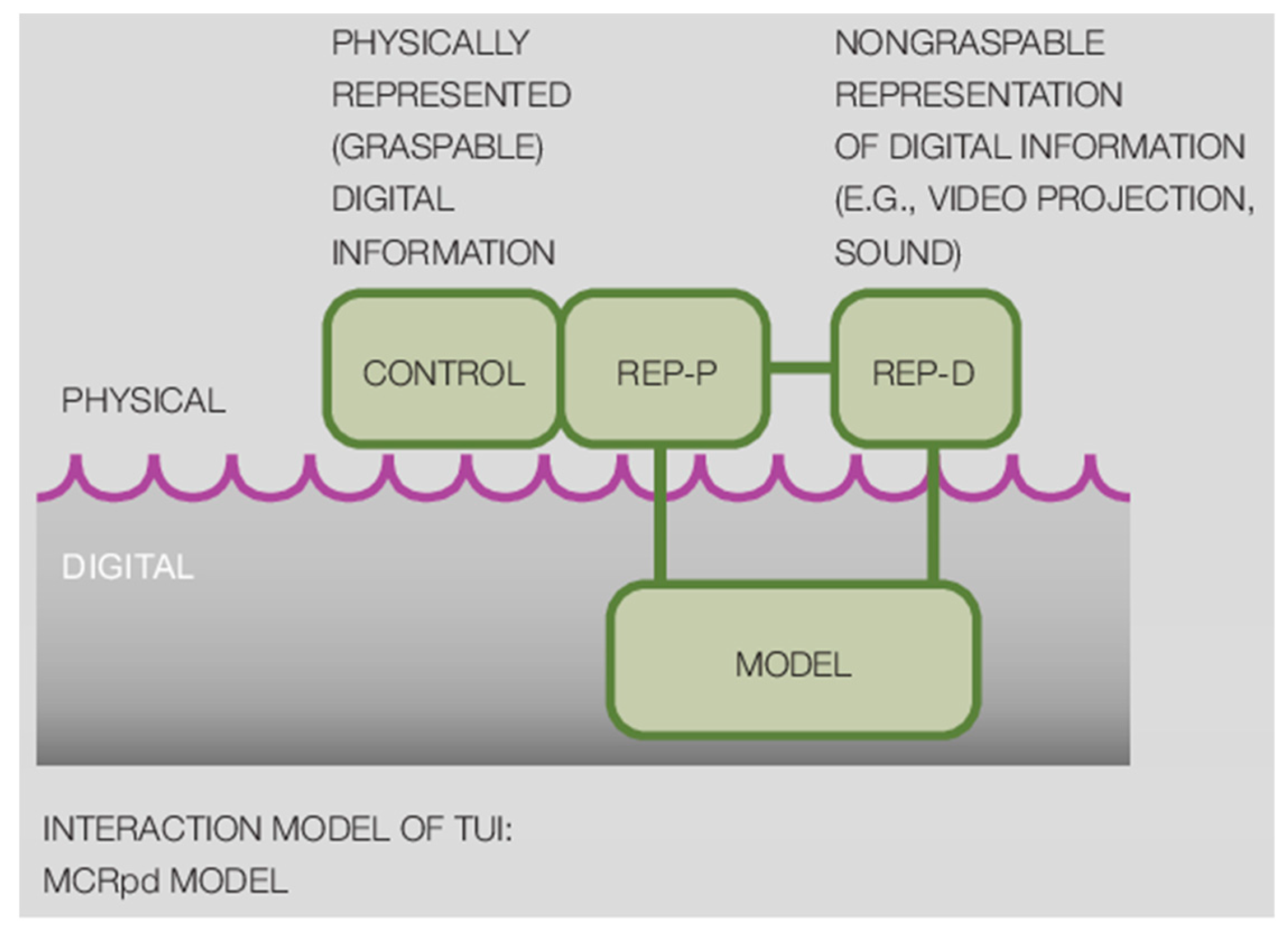
8]. In order to articulate ideas about representation and control of digital phenomena in an interactive system, the MCRpd (Model-Control-Representation, physical and digital,
Figure 1) interaction model is proposed [
2]. The MCRpd makes the following distinction. On one hand, there is the underlying digital information, i.e., the bits and bytes, referred to as model in the diagram. On the other hand, there are different representations of this model in the real world. These representations can take two forms: physical (REP-P) and digital (REP-R) representations. Physical representations are artifacts that embody digital information. Digital representations are computationally mediated entities without physical form (e.g., video projection and audio). Both physical and digital representations are said to be perceptually coupled. This coupling is indicated via the horizontal line in the diagram.
From this model, we have inherited the idea that digital phenomena are represented in the physical world through two kinds of representations. These representations are those that feel physical, and those that feel digital. We called them physical events and digital events. The coupling between them—the green horizontal line on the diagram—is the coupling that we investigate in our research.
2.2. The Interaction Frogger Framework
Wensveen et al. [
3] translated the concept of coupling into a framework for product designers. The interaction frogger framework was developed to make people’s interaction with digital products natural and intuitive. The reference for natural interaction is the interaction with simple mechanical products (e.g., cutting paper with a pair of scissors). The framework focuses on the coupling between user action and product function. In an interaction routine, the two factors constantly alternate. A user action results in a product function, and vice versa. The coupling is the mutual relationship between the two factors. It describes how user action and product function are related to each other, and to what extent the user perceives them as similar. The framework suggests that when user action and product function are united on six aspects, they are experienced as naturally coupled. In the context of this paper, we retain three of these six aspects. These three aspects are:
Time: User action and product function coincide in time;
Location: User action and product function occur in the same location;
Direction: User action and product function have the same direction of movement.
2.3. The Aesthetics of Coupling
In our previous work, we deepened the concept of coupling by considering it as a source of aesthetic experience [
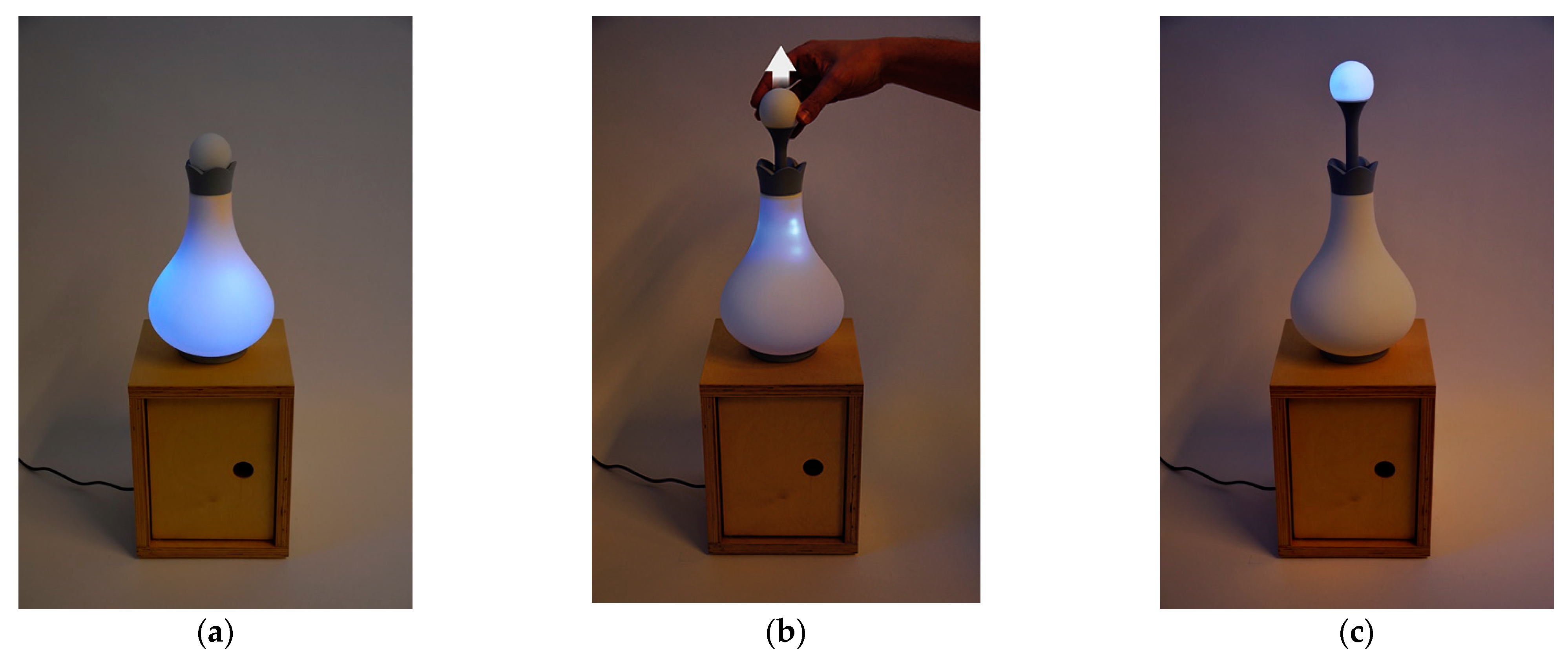
1]. As described earlier in this paper, we distinguish physical and digital events. Whether these events are initiated by the user or the product, as emphasized by the Interaction Frogger Framework, is of secondary importance to us. We argued that the aesthetics of coupling uniquely play between two events: physical and digital events. The intrinsic difference in the nature of both events makes up the essence of the aesthetics. Physical events are persistent and static, while digital events are temporal and dynamic. The designer brings both events very close to one another, so that they are perceived by the user as one coherent, harmonious user experience. At the same time, the user is very aware of the different natures of the two events, which clearly makes a complete unification impossible. This inherent paradox, which is the tension field between being apart and together at the same time, causes feelings of surprise and alienation that constitute the aesthetics of coupling. The first author, together with Floor Van Schayik, designed a night lamp that illustrated this concept (
Figure 2). A video of this night lamp can be found in
Supplementary Material: Video S1-NightLamp. When the user pulls up the sphere at the top of the lamp, the light inside the lamp moves with it and jumps into the sphere at the end of the movement. As such, the reading lamp becomes a night lamp. In this example, the aesthetics of coupling lie in the contrast between the physicality of the sphere and the intangibility of the light inside the lamp.
3. The Audi Demonstrator
3.1. Background
We explored SAR in a human–cobot workplace [
26]. A cobot, or collaborative robot, is a relatively small industrial robot designed for direct human–robot interaction. The context for our research project was provided by Audi Brussels (
https://www.audibrussels.be, accessed on 17 May 2023) and Kuka (
https://www.kuka.com, accessed on 17 May 2023). In the production line for the body panels of the Audi A1 in Brussels, Audi needed a workplace that could measure and inspect the adhesion quality of the fold glue joints for each panel (doors, hood and trunk). In this workplace, a single operator works together with a cobot: the Kuka LBR iiwa. This cobot tracks the contour of the body panel using contact force feedback, and checks the adhesion quality of the fold glue joints through means of an ultrasonic sensor.
We conducted a few preliminary ideations on the operator’s interaction with the workplace and the cobot. We adopted the stance that interaction with projected content in workplaces is not going to replace today’s interaction styles, but will coexist with and complement them [
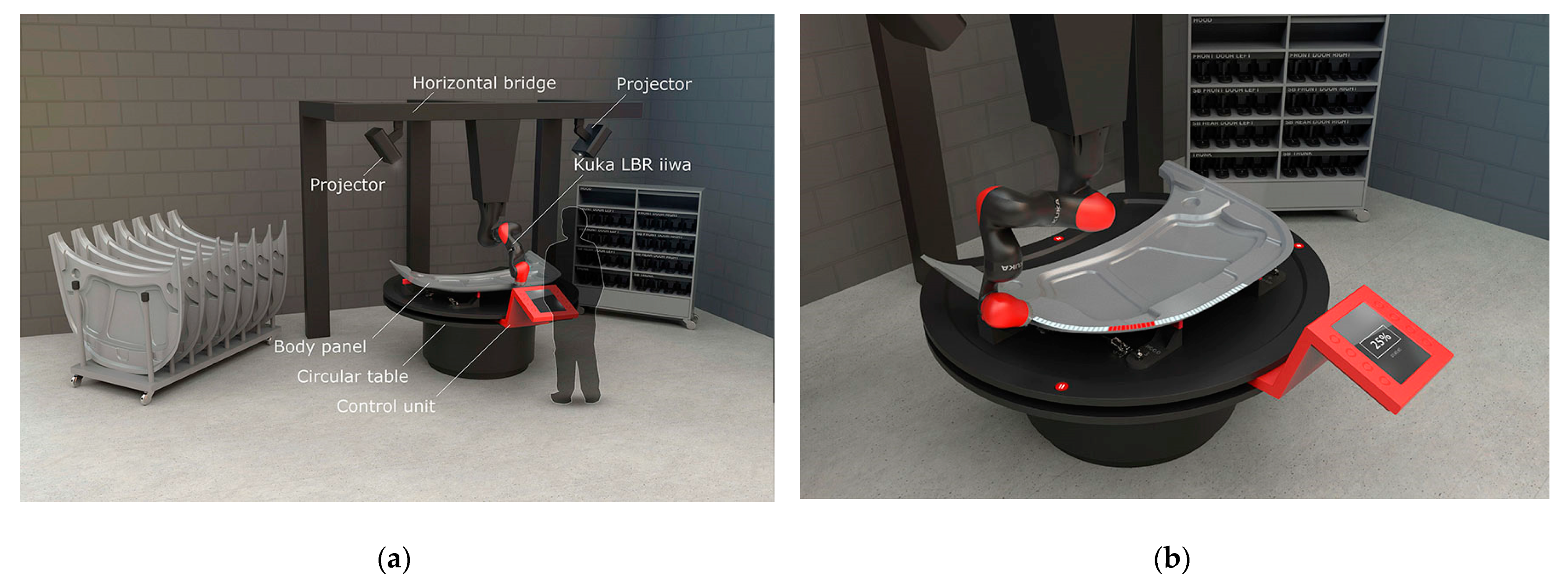
21]. This assumption resulted in a preliminary concept for the Audi workplace, defined in 3D CAD (
Figure 3). The concept consisted of a circular table and a control unit, containing a display-button setup. The Audi A1 body panels are placed manually on the table, one at a time. Above them, a Kuka LBR iiwa cobot hangs upside down from a horizontal bridge, with its work envelope covering the entire table surface. On either side of the cobot, two projectors are mounted on the bridge, augmenting the table and body panels with projected images. The idea is that the operator steers and controls the cobot with the control unit. The cobot moves over the body panel while touching its contour and ultrasonically senses the adhesion quality of the glue joints. Relying on several SAR studies [
27,
28,
29], we decided that the visual feedback on this measurement should be projected in real time on the body panel itself, rather than appearing on a separate, isolated display.
3.2. Description of the Demonstrator
We designed and built a 1/6 scale model of the Audi workplace (
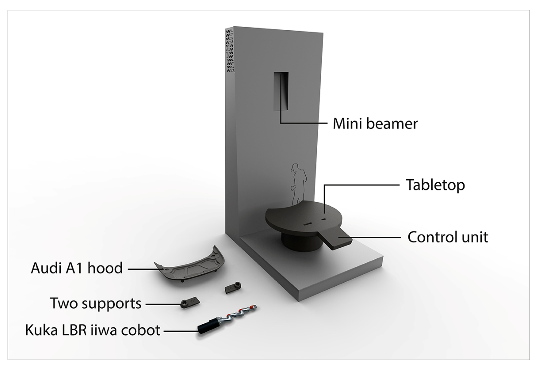
Figure 4). The purpose of this scale model was to inform and inspire people from the Flemish manufacturing industry. With this model, demonstrations are given by one operator to an audience of around ten people. The setup is made of sheet metal and SLS (Selective Laser Sintering) parts. It features a horizontal surface, on which the circular tabletop is mounted, and a vertical wall containing a mini beamer. Adjacent to the circular tabletop, a rectangular surface represents the control unit. The beamer simulates the control unit’s multi-touch display and projects images onto the table surface and the objects that are placed on it: an adapted replica of the Audi A1 hood and two positioning supports. Finally, the setup includes an adapted scale model of the Kuka LBR iiwa, which is used by the operator as a puppet in a theatre.
3.3. Description of the Interaction
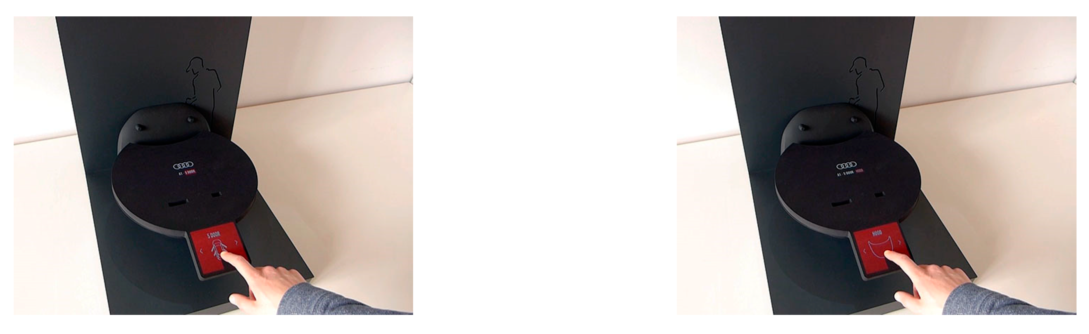
The interaction starts at the control unit. The operator stands in front of it and performs menu navigation actions on the multi-touch display. He/she selects the type of car, in this case a five-door Audi A1, and the body panel, in this case the hood (
Figure 5).
When the hood is selected, the hood icon moves upwards, leaves the display, and slides onto the augmented tabletop, where it grows into a full-scale positioning contour (
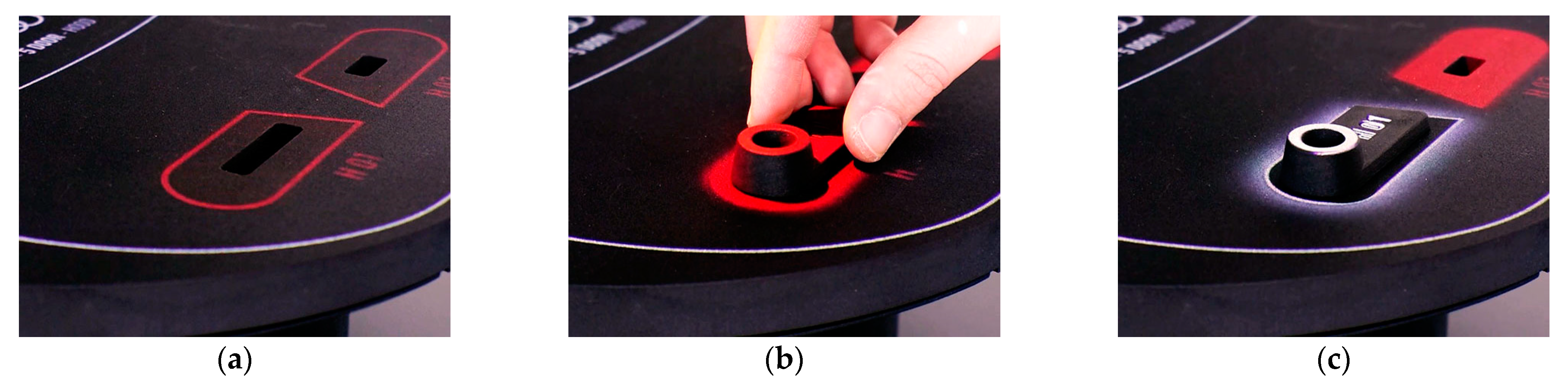
Figure 6). The operator moves along with this motion, leaves the control unit, and stands at the tabletop. From there on, he/she is guided through projected work instructions. The contours of both supports are shown in red (
Figure 7a). The operator positions both supports on the table (
Figure 7b). When the system detects the correct placement of each support, the red pulsating projection turns white and adapts to the shape of the supports (
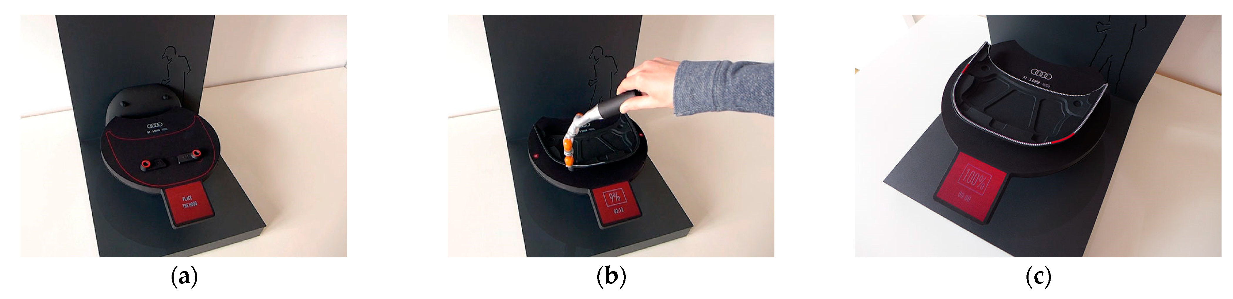
Figure 7c). Next, the outline of the hood is projected in red (
Figure 8a). The operator places the hood on both supports, which help to ensure a correct positioning. Next, the operator presses a start button on the control unit, and the cobot begins to track the hood contour and measures the adhesion quality of the glue joints (
Figure 8b). The result of this measurement is projected in real time onto the hood itself: white dots indicate good adhesion quality, while red dots indicate poor quality (
Figure 8c).
3.4. Discussion
The Audi demonstrator combines two interaction styles: interaction with a multi-touch display, and interaction with a spatially augmented tabletop. We see novelty in the way the demonstrator couples these two interaction styles. We focus on two particular couplings, which are further developed in the demonstrators presented in the next two sections.
3.4.1. Coupling 1-On-Screen Event and Projected Event
The demonstrator is divided into two distinct working zones: the control unit with a multi-touch display, and the tabletop with SAR (
Figure 4). This split-up determines the form semantics of the workplace. The square shape of the multi-touch display is adjacent to the circular shape of the SAR tabletop, forming a continuous surface. This continuity is further extended in the coupling of both on-screen and projected events. This coupling is clearly visible in the following moment. When the user selects the hood by touching the icon on the display, this icon moves upwards and slides onto the augmented tabletop (
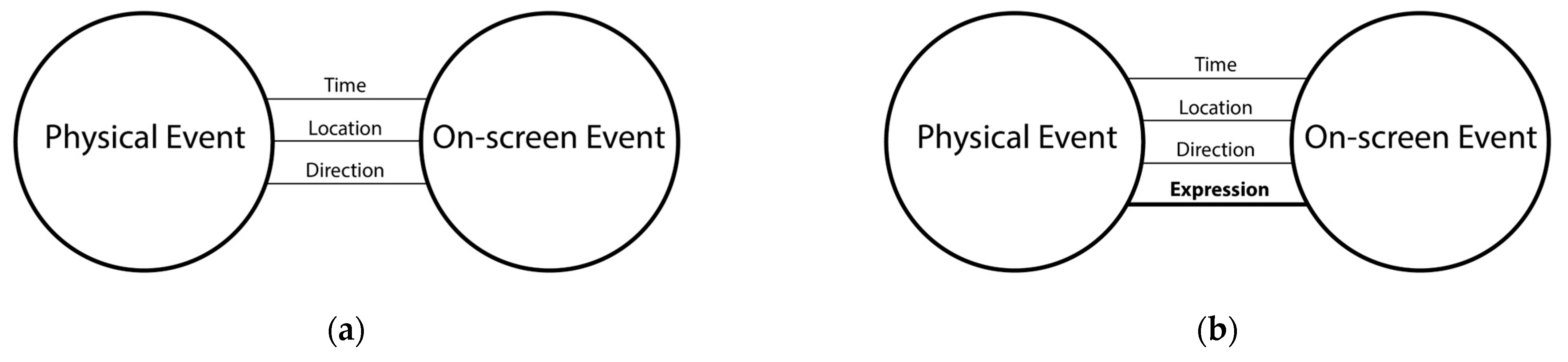
Figure 6). At this point, the projection takes over the on-screen imagery. The transition between the on-screen event and the projected event leads the operator from the control unit to the tabletop. In the design process, we relied on the rules of the Interaction Frogger Framework [
3]. Both events are coupled on the aspects of time, location, and direction (
Figure 9).
They happen one after the other, thus in the same time span;
Where the icon leaves the display, it is projected onto the tabletop; thus, both events have the same location;
The direction of the icon’s movement on the display is the same as the direction of its movement on the tabletop.
It is important to note that the three different couplings combine aspects that are already present in each event separately. Each event occurs at a particular time, on a particular location, and has a movement with a particular direction. Designing the coupling between them is clear and straightforward because the goal is clear: to ensure that the three aspects of both events are in line with each other. The benefit of these three couplings lies in the domain of ease of use. Unity of time, location, and direction between different events makes the events resonate with each other. These couplings create uniformity, coherence, and order in different movements and actions, and promote the naturalness of interaction, as already implied through the Interaction Frogger Framework. They make the functioning of the workplace logical and, as such, easy to read. They reveal the meaning of the workplace to the operator. We call them couplings of meaning.
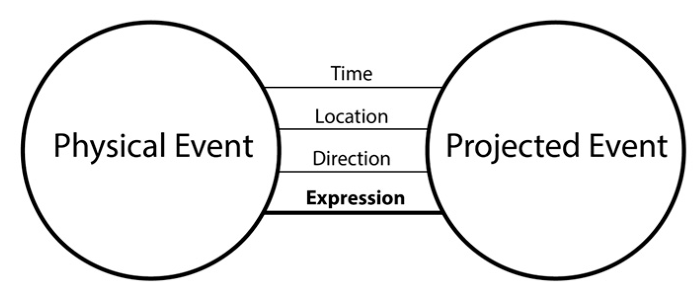
However, there is another factor involved. The transition between the two different interaction styles, i.e., multi-touch interaction on a display and in situ projection on an augmented tabletop, is emphasized through the movement of the hood icon. The icon literally leaves the display and the GUI paradigm and enters the real world, where it grows into a full-scale work instruction. This transformation is not already present in each event separately. It emerges from the coexistence and interplay of the three other couplings. Its merit lies in the fact that it adds expression and engagement to the interaction, as it touches on aesthetics and emotional values. In former work, we referred to this phenomenon as the aesthetics of coupling. In this paper, we want to deepen our thinking. We state that both events show unity on a fourth aspect, next to time, location, and direction. We call this aspect expression (
Figure 9). We call the coupling on this aspect coupling of expression.
We want to note that our definition of coupling of expression should not be confused with Wensveen’s definition [
3], in which the user expresses him- or herself during the interaction with a product. This expression is then reflected in the product’s function. For example, cutting paper with a pair of scissors while feeling nervous and rushed will result in sloppy incisions.
3.4.2. Coupling 2: Physical Event and Projected Event
Another form of coupling occurs when the contours of both supports are projected onto the tabletop in real scale and all in white. At a certain point, the contour of the first support starts to pulsate slowly in red (
Figure 7a). This event nudges the operator to place the first support. Once the operator has completed this task (
Figure 7b), the projection changes color from red to white and adapts to the shape of the support (
Figure 7c). The projection highlights the support’s identification number, as well as its peg hole, in which the hood will eventually be positioned. The placement of the support by the operator is a physical event that is coupled to a projected event. This coupling occurs on two aspects: time and location (
Figure 10).
The moment the operator positions the support on the tabletop, the projection appears;
The projection appears on the support itself, not next to or near it.
3.4.3. Learnings for the Next Iteration
After building the demonstrator, and presenting it to people from Audi, Kuka and the Flemish make industry, we came to the conclusion that the demonstrator indeed elicited the aspects of coupling mentioned above, but did not exploit their full potential. We saw three angles to further explore the design space. Firstly, we wanted to build a real scale setup to enhance the sense of reality and immersion. Secondly, we wanted to create a real multi-touch display, rather than a simulated one, to increase the contrast between on-screen and projected events. Thirdly, we wanted to further explore coupling 2, i.e., the coupling between the supports and the projection. We decided to build a second installation, together with Kuka, in order to fulfil these intentions.
4. The Kuka Mockup
4.1. Background
At this point in the research project, the plan rose to build a real demonstrator with a working cobot. In order to understand this idea, we decided to first construct a mockup out of wood, 3D printed components and spare parts. Since our focus was on interaction and coupling, rather than on force-based contour tracking and echolocation, we chose an artefact with a less complex 3D contour than the Audi A1 hood: a wooden longboard.
4.2. Description of the Mockup
The demonstrator was more an experience prototype or mockup than a full-blown demonstrator (
Figure 11). It consisted of two ladders on which we mounted an aluminum beam with two projectors, and a full-scale wooden mockup of the Kuka LBR iiwa cobot. We built a wooden tabletop and a control unit with a working multi-touch display, and placed it under the beam structure. We designed specific supports for the longboard, which could be placed on the tabletop.
4.3. Description of the Interaction
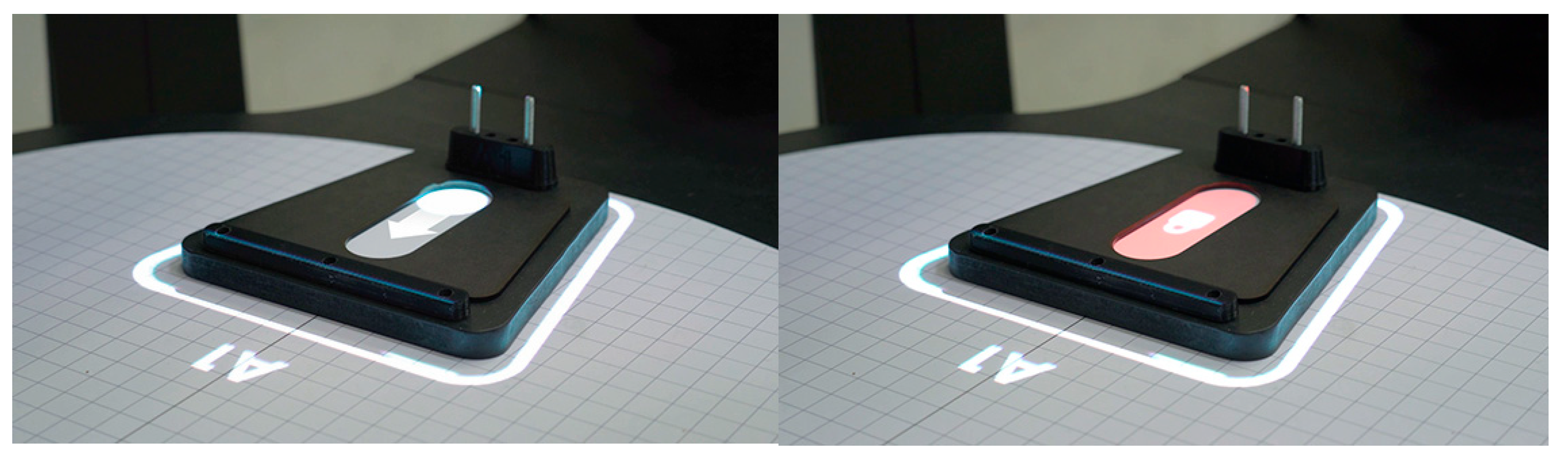
The interaction routine is very similar to that of the Audi demonstrator. The idea is that the cobot measures the contour of a longboard instead of the Audi A1 hood and compares it with a reference contour. Another difference lies in the supports. Both longboard supports contain a dedicated projection surface, which is in the form of a pill-shaped cavity, printed on cardboard. Once the support is placed on the work surface, an identically shaped icon is projected into this cavity (
Figure 12 and
Figure 13). The projected icon contains a slider that moves from one side of the printed cavity to the other, naturally guided via its boundary, informing the operator that the system has locked the support to the work surface (
Figure 14). When the cobot has completed its measurement task, the zones with form deviations are indicated by a red light (
Figure 15b), and the operator marks the zones with physical stickers (
Figure 15c).
4.4. Discussion
During the design of this demonstrator, we developed the two coupling themes that we had begun to explore in the Audi demonstrator.
4.4.1. Coupling 1–On-Screen Event and Projected Event
The transition from on-screen to projected event is realized literally through the presence of an operational multi-touch display on the control unit. The coupling between the two events is now a transition between two different media, which reinforces the transformative aspect of the interaction routine and, thus, the expressive power of the coupling. As soon as the icon disappears from the top of the display, it reappears as a projection on the tabletop, continuing the same movement (
Figure 12). This process creates the effect of the icon literally crawling out of the display and into the real world. The sense of magic and surprise [
3] that this process creates is the result of coupling of expression (
Figure 9). We want to emphasize that, in our previous work, we stated that this form of aesthetic was only possible in the coupling between physical and digital events. In this demonstrator, both coupled events are digital in nature.
4.4.2. Coupling 2–Physical Event and Projected Event
We further explored Coupling 2 from the Audi demonstrator. The result of this exploration is visible in the placing of the longboard supports on the work surface (
Figure 13). The manual placement of the support causes the appearance and movement of a projected element in the support’s cardboard cavity, reflecting the status change in the support from unlocked to locked (
Figure 14). With respect to the Audi demonstrator, we added coupling of direction to the concept, as the projected element follows the physical contour of the cavity. As a result of this design intervention, something remarkable happens: the support, which is a physical and inanimate object, suddenly has a moving part and seems to be brought to life through the projection. We consider this event to be coupling of expression (
Figure 16).
4.5. Learnings for the Next Iteration
As the cobot in the Kuka mockup was just a static wooden dummy, its movement capabilities remained underexposed, as do its coupling possibilities with other events. In our final demonstrator, we wanted to include a real, working cobot.
5. The Kuka Demonstrator
5.1. Background
Together with the people from Kuka, we designed and built a workplace around a limited set of cobot tasks, the most important of which was to measure the contour of a longboard deck and compare it to a reference contour. The envisaged workplace would contain a real Kuka LBR iiwa, real force-based contour tracking, and real-time projection of the measurement results onto the longboard itself.
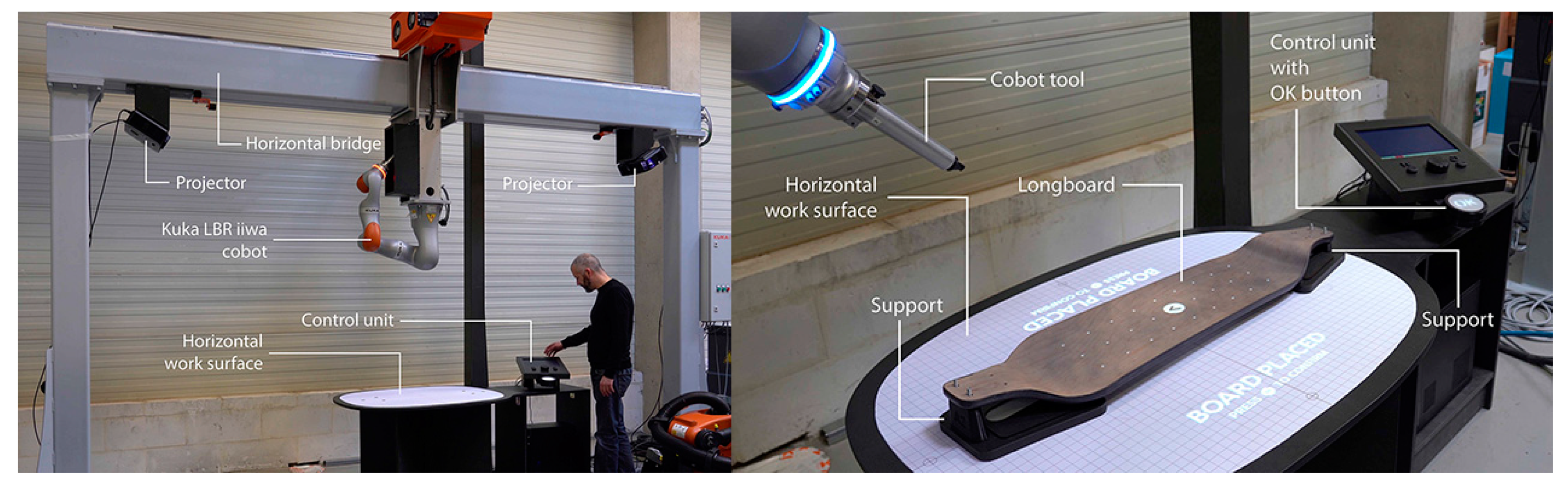
5.2. Description of the Demonstrator
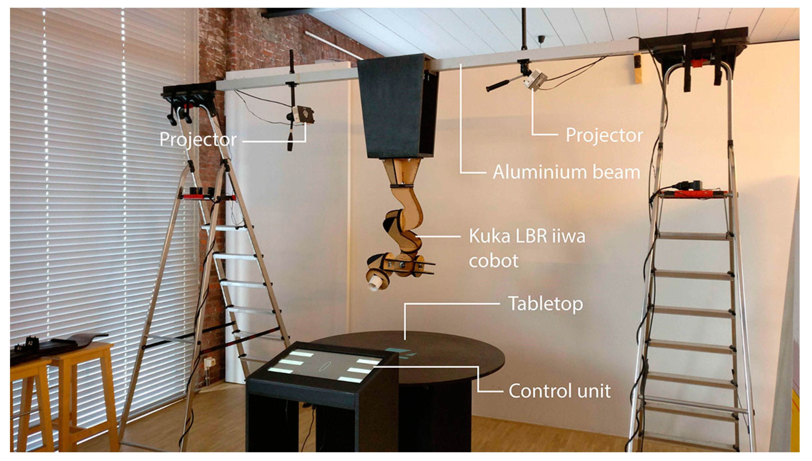
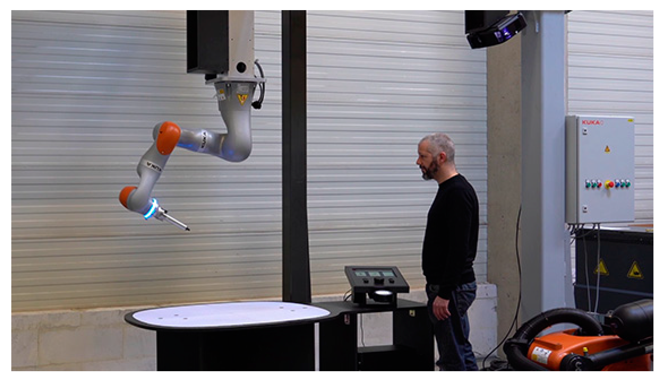
The demonstrator features a horizontal bridge of approximately 3m high (
Figure 17). Beneath the bridge is a workbench containing two different work zones: a control unit with a display-button setup and a horizontal work surface. On the work surface, a longboard can be positioned and mounted by the operator using two supports. Above it, a Kuka LBR iiwa cobot hangs upside down from the bridge, with its movement envelope covering the entire work surface. On opposite sides of the cobot, two projectors are mounted on the bridge. We designed a special tool, which is mounted on the cobot itself, that allows it to physically touch and track the contour of the longboard, thereby sensing and processing the applied force. The two work zones involve different operator tasks. The zone with the control unit serves to select tasks through menu navigation. The work surface with the cobot and the projection is conceived to perform physical tasks, in cooperation with the cobot. Both work zones are connected via the large OK button below the control unit. This large button is located between the two different work zones and always remains accessible, whether the operator is working at the control unit or the work surface.
5.3. Description of the Interaction
5.3.1. Interaction with the Control Unit
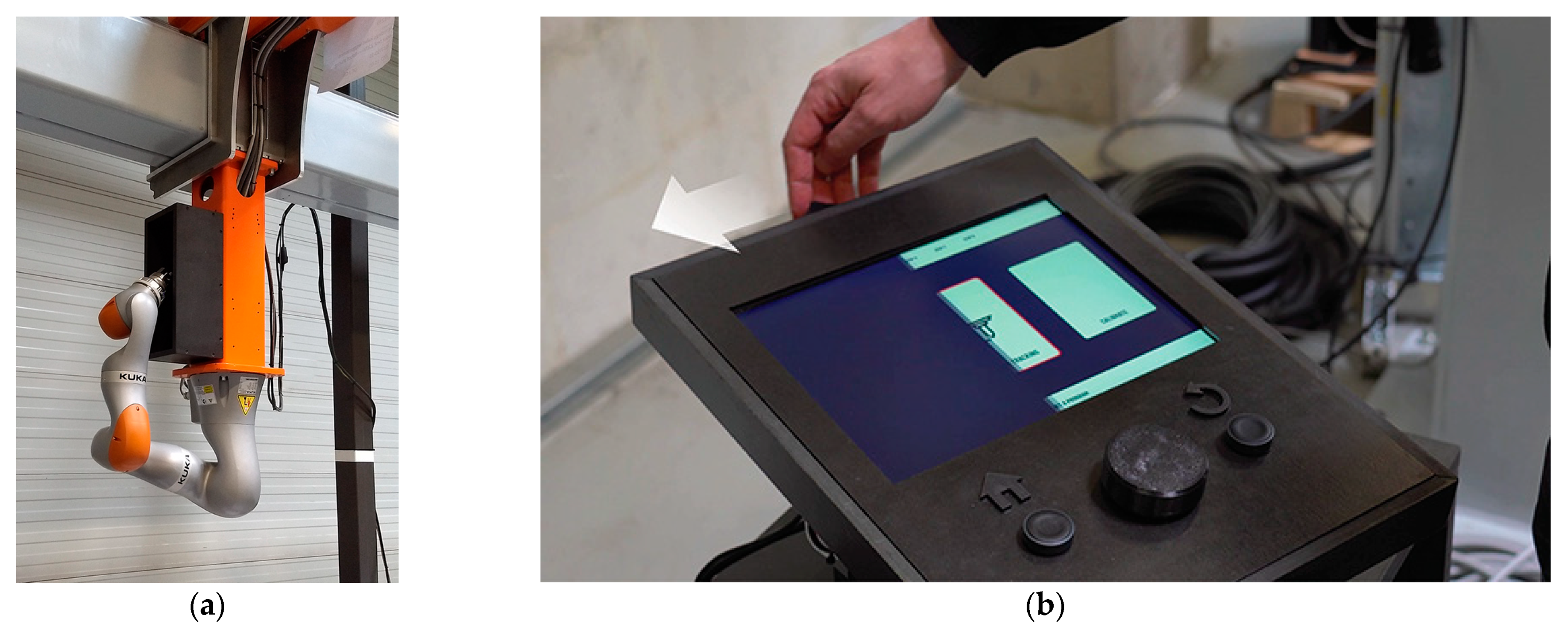
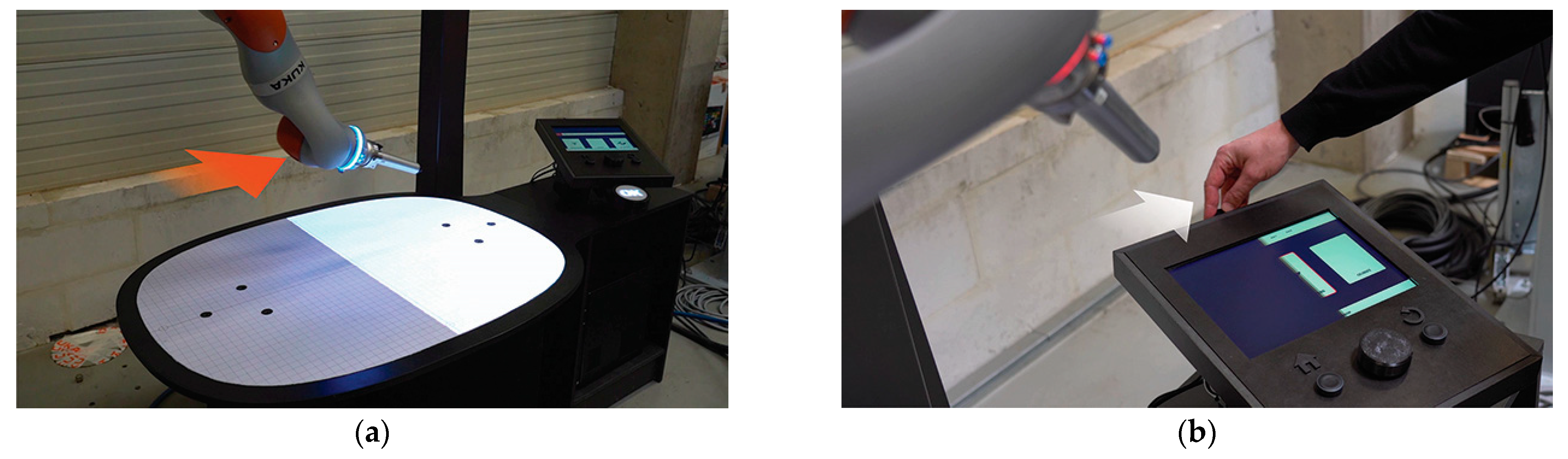
In a first phase, the cobot is in sleep mode (
Figure 18a). We provided a box, attached to the bridge, into which the cobot can retreat, portraying a clear image of being at rest. The operator walks to the control unit and activates the system by pushing the slider button on the control unit to the left (
Figure 18b). On-screen, a black curtain slides away together with the button, and the control unit is activated. As a result, the cobot above the work surface wakes up and moves towards the control unit. It adopts an attentive posture, as it seems to be looking at the display, together with the operator. We call this dialogue mode (
Figure 19a). The operator navigates through the menus using a traditional rotary dial and push button interface (
Figure 19b). As he/she turns the dial, the menus move horizontally.
5.3.2. Transition between Two Work Zones
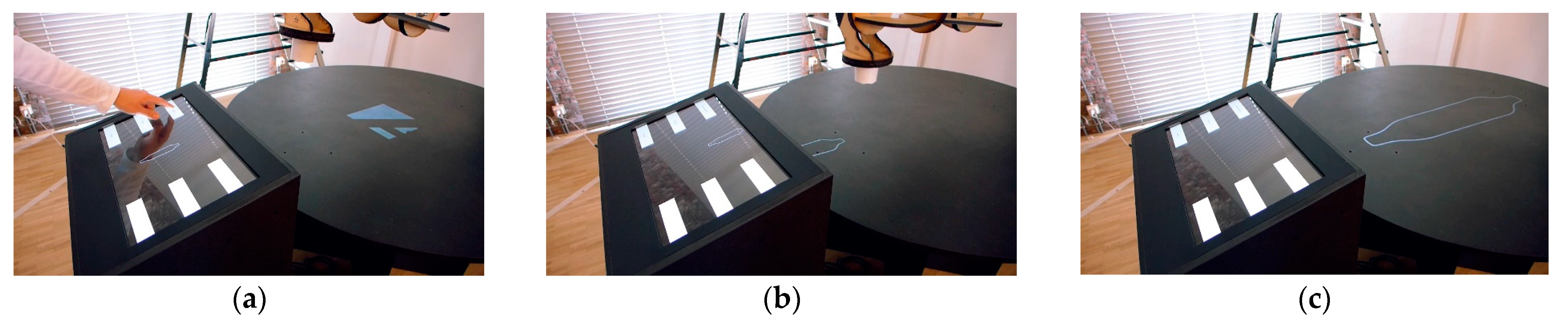
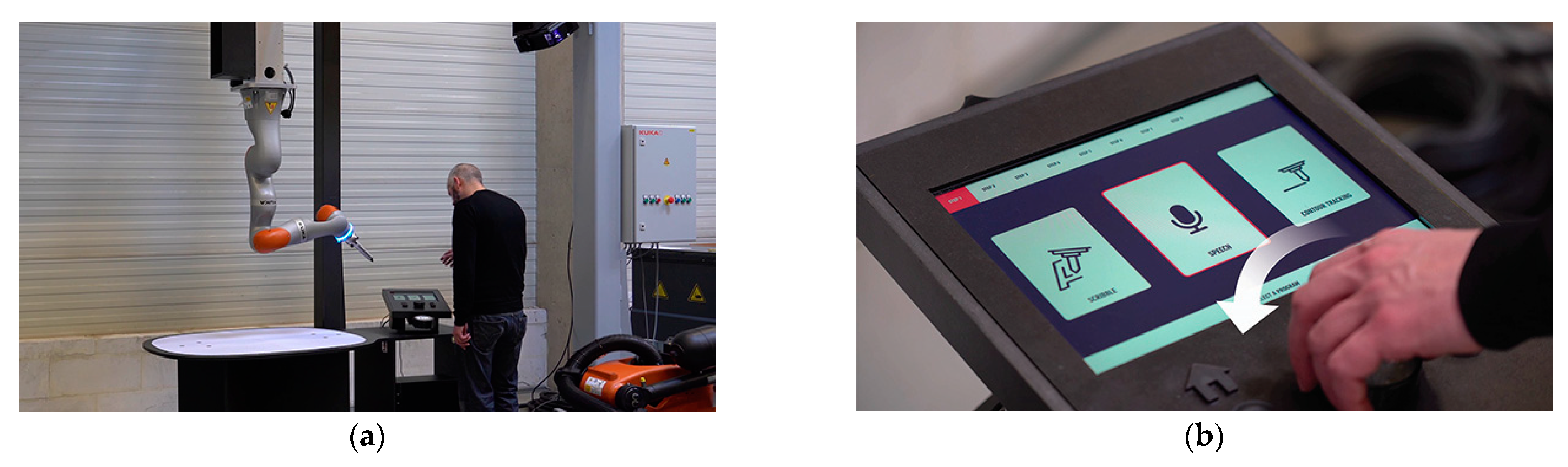
The operator selects to perform a contour tracking task, and confirms this selection by pushing the rotary dial (
Figure 20a). The cobot then moves away from the control unit towards the work surface. At this point, the on-screen images on the control unit’s display move downwards, as if they flow onto the table below. At the same time, a projection is generated on the work surface, showing a sliding image that moves away from the control unit and fills the entire work surface. The cobot appears to “pull” the on-screen image out of the control unit onto the tabletop (
Figure 20b). The operator is guided from one work zone towards the other based on the physical movements of the cobot and the movements of on-screen and projected images. The cobot is now looking at the work surface, and is in standby mode. Work instructions are projected onto the work surface (
Figure 21).
5.3.3. Manual Mounting of the Supports and the Longboard
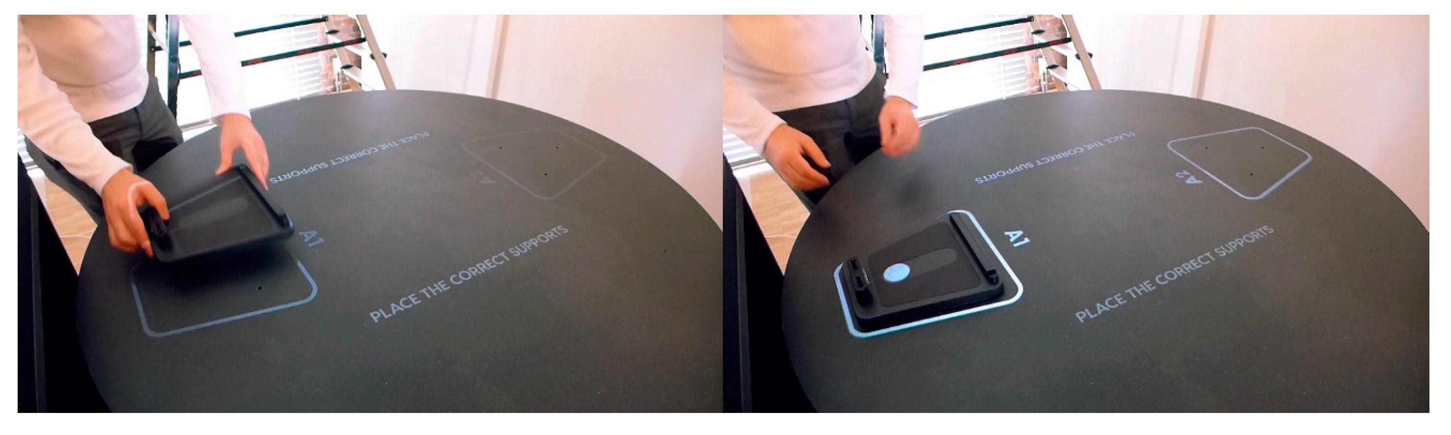
The operator follows the instructions on the work surface and mounts the supports (
Figure 22a). After each support is mounted, the operator pushes the OK button (
Figure 22b), and a moving icon is projected into a cavity on each support, indicating that the system has locked the support (
Figure 23). The operator then places the longboard on the supports. This action is detected via the system, which responds with a projection on the longboard itself (
Figure 24). The operator continues to follow the work instructions and manually bolts the longboard in place. When this task is completed, he/she pushes the OK button. The cobot approaches the longboard.
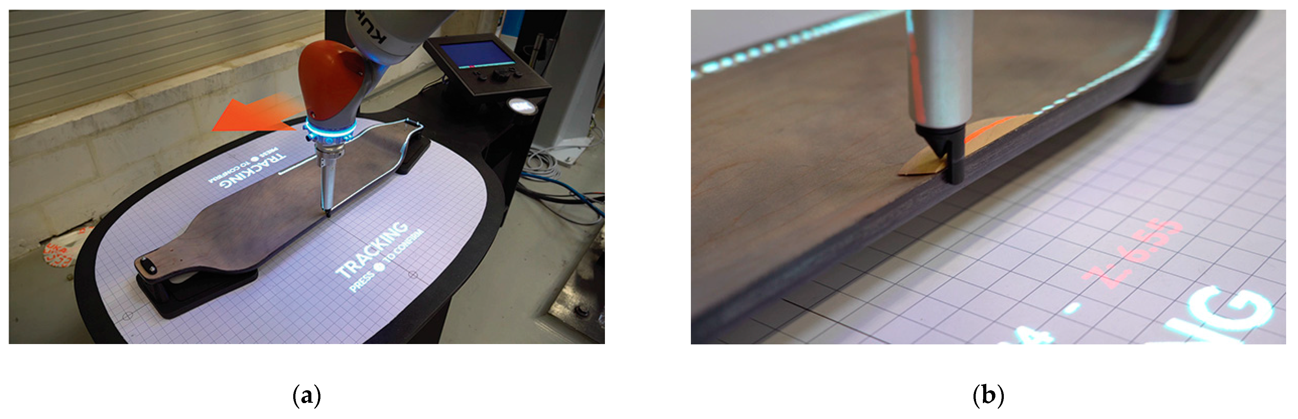
5.3.4. Force-Based Contour Tracking
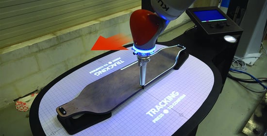
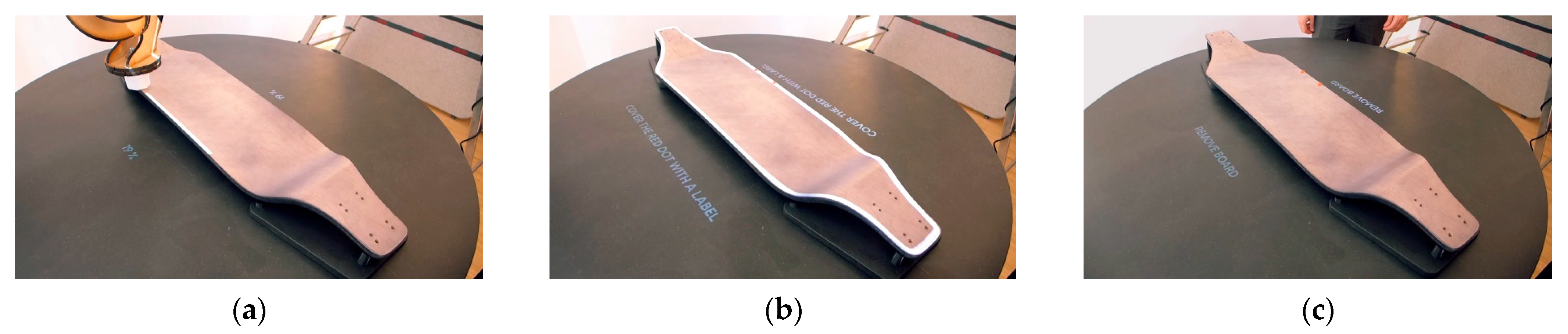
The operator pushes the OK button, and the cobot begins to track the contour of the longboard. The tracked path is projected onto the longboard in real time (
Figure 25a). The cobot is now in scan mode. In a first pass, the cobot recognizes the longboard contour and uses it as a reference for other longboards. When a longboard with a deviating contour is checked via the system (in the video, the deviation is added by the operator), the deviation is detected and marked with a red projection image on the longboard itself (
Figure 25b). Correspondingly, the deviation value is projected on the work surface. After tracking, the operator pushes the OK button.
5.3.5. Clearing the Work Surface and Shutting down the System
The operator removes the longboard and the supports, following the instructions on the work surface. When the work surface is empty, the OK button is pushed, and the cobot guides the projected images into the control unit with a physical movement (
Figure 26a). The control unit is reactivated, and the cobot is back in dialogue mode. To deactivate the system, the operator moves the slider on top of the control unit to the right, and the on-screen image reacts accordingly (
Figure 26b). The cobot returns to sleep mode (
Figure 18a).
5.4. Discussion
The fact that we had the possibility to conceive and craft a semi-functional demonstrator on real scale, with a fully-functioning cobot, gave us the chance to further explore Coupling 1, which had already appeared in the two earlier demonstrators. Coupling 2 was refined, though its concept remained the same. In addition, we added a display-button setup as control unit, with specific couplings.
5.4.1. Coupling 1: On-Screen, Projected and Cobot Event
We considered the movements and postures of the cobot not only as a functional given, but also as a crucial part of the workplace’s form semantics and affordances. We realized this intention by relying on the concept op Mode of Use Reflected in the Physical State (MURPS) [
30]. This means that we designed the different postures of the cobot in such a way that they non-verbally express the state of the workplace’s operating system. In this respect, we distinguish between sleep mode (
Figure 18a), dialogue mode (
Figure 19a), standby mode (
Figure 21), and scan mode (
Figure 25a). Moreover, the movements of the cobot are coupled to projected events. This coupling is most prominent in scan mode (
Figure 25a), where the cobot tracks the contour of the longboard, and the result of the measurement is projected onto the longboard’s surface.
We further explored Coupling 1 by enriching it with cobot movements. This approach led to a new insight. When the operator ends the dialogue mode by pushing the rotary dial (
Figure 20a), three events are coupled: a cobot event, an on-screen event, and a projected event (
Figure 27). The three events occur at the same time and at the same location, and share the same speed and direction. In addition, the couplings create the impression that the cobot is actually pulling the image out of the display and spreading it onto the tabletop (
Figure 20b). A similar coupling occurs at the end of the contour tracking task. The projected images slide back from the work surface in the control unit (
Figure 26a), seemingly being pushed by the cobot. This effect, where the cobot appears to pull images out of the display onto the tabletop and back, surpasses the three couplings of meaning and reinforces the coupling of expression. The cobot becomes an expressive medium that grasps intangible elements and moves them from one physical place to another.
5.4.2. Additional Couplings of the Control Unit: Physical Event and On-Screen Event
What coupling of expression entails is clearly illustrated by the difference between two interaction routines on the control unit of the Kuka demonstrator. The first meaning is the turning of the rotary dial, which causes the different task icons on the display to move sideways, either to the left or to the right (
Figure 19b). The rotary dial is positioned near the display with the task icons, its rotation is immediately translated into a lateral movement of the icons, and the icons move left or right, according to its direction of rotation. As such, there is coupling on the aspects of time, location, and direction (
Figure 28a). However, the interaction feels rather plain and barely expressive. This outcome is because the coupling of direction is not very strong: the dial rotates, while the icons translate. The fact that a rotary dial allows this degree of randomness makes it a popular control element in many commercial GUIs, but it also makes its interaction standardized and generic. This method is very different to the second routine. This routine involves pushing the slider button at the top of the display, which causes a black curtain to slide across the display, activating or deactivating it (
Figure 18b and
Figure 26b). Again, there is coupling on the aspects of time, location, and direction. In this case, however, the coupling of direction is strong. Both the slider button and the on-screen curtain translate in the same direction, over almost the same distance. For the user, it feels as if the slider button is directly attached to the on-screen curtain, as if he/she were dragging a physical curtain across the display. The specific design and coupling of the two events, the pushing of the slider button, and the movement of the on-screen curtain results in coupling of expression (
Figure 28b).
6. Discussion
In this section, we look back at the delivered work. We discuss the couplings that emerged across the three demonstrators, and reflect on how they have refined our understanding of coupling.
6.1. A Wealth of Events
In our previous work, we assumed two types of events—physical events and digital events—with coupling being the relationship between them. During the conception and creation of the three demonstrators, it became clear that this division was not sufficiently fine-grained. We encountered two types of digital events: on-screen events and projected events. It is to be expected that, as different forms of AR (tablet-based AR, SAR, head-mounted display-based AR) are adopted in workplaces, the number of digital event types will increase. In this scenario, we are thinking of holographic events, sound events, etc. Physical events can also be categorized in more detail. During our research, we already came across the cobot event; however, a further classification of physical events urges itself. Event classifiers include user movements, physical events performed with control elements, actuated events, etc. Digital events can be coupled to physical events, but also to other digital events. This fact clearly surfaced in our RtD process: in the three demonstrators, we defined couplings between on-screen and projected events, which were both digital in nature. Similarly, couplings between physical events are already commonplace. Any kitchen appliance that connects the pushing of a button to the activation of an electric motor couples two physical events.
In addition, coupling is not necessarily limited to two events. In the Kuka demonstrator, we coupled three events instead of two: an on-screen event, a projected event, and a cobot event. Four or five events may also be coupled together. Whether these events are physical or digital in nature is less important.
As digital technology evolves, and as digital phenomena break free from displays and enter the physical world in projected or holographic form, the dichotomy between the digital and the physical, which has been the blueprint for embodied interaction to date, becomes less dominant [
31]. We want to open the door to an understanding of coupling that transcends the traditional bridging of the physical and the digital. Designers of digital products and systems need to be primarily concerned with the intuitive and engaging coupling of different events, regardless of their nature, rather than making interaction with digital phenomena more physical.
6.2. From Meaning to Expression
We defined four aspects of coupling. Three of them came directly from the Interaction Frogger Framework: time, location, and direction. We called them couplings of meaning. In the discussion about the Audi demonstrator, we stated that they are relatively easy for designers to understand and employ, as they only require the organization and alignment of aspects that are already present in each event separately.
The fourth aspect of coupling—expression—is more difficult to grasp, because it is not already present in each individual event. Instead, it emerges as a result of the other couplings and the design of the workplace in general. Coupling of expression stems from the aesthetics of coupling, which we discussed in
Section 2.3. However, the aesthetics of coupling, as well as the MCRpd interaction model, relied on the dichotomy between the physical and the digital realms. If this dichotomy fades into the background, then how can we define coupling of expression and its relation to coupling of meaning?
Coupling of expression emerges as a consequence of, and as a contrast to, coupling of meaning [
32]. In order to set the stage on which coupling of expression can perform, at least some realization of couplings of meaning is necessary. Couplings of meaning form, as it were, a reference, i.e., a background against which coupling of expression is perceived and felt by the operator. This stage or background has an orderly, logical, and natural character, as the various coupled events resonate with familiar, often Newtonian laws and common sense knowledge about the physical world [
33]. However, when coupling of expression appears on the stage, this familiar character is challenged and transcended, as the coupling appears to violate the established laws. The resulting user experience enters the realm of magic, beauty, and surprise, and appeals to the operator’s emotions, rather than to his/her reasoning. We give three examples:
In the Kuka mockup, the movement of the on-screen longboard icon is adopted using the projected longboard icon; thus, it appears to leave the display and slide across the tabletop (
Figure 12). Both icons appear to be one, which is an effect created via the couplings of time, location, and direction. The expressive appeal of the interaction routine lies in the fact that the operator clearly realizes that the two icons are not the same. They have inherently different aspects. In the Kuka demonstrator, this movement is reinforced through the cobot movements. The effect is that the cobot pulls the on-screen content out of the display and spreads it across the tabletop (
Figure 20b).
In the Kuka mockup and the Kuka demonstrator, the pill-shaped cavity of the support is filled with a projected slider (
Figure 14 and
Figure 23). Couplings of time, location, and direction ensure that the slider carefully follows the contours of the physical cavity, as if it were a real slider. The expression comes into play when the operator realizes that the slider is not real.
In the Kuka demonstrator, pushing the slider button on the control unit causes the on-screen curtain to slide simultaneously in the same direction at almost the same pace (
Figure 18b and
Figure 26b). For the operator, it feels as if the curtain is physically attached to the slider, although he/she clearly sees that the curtain is only an on-screen representation, rather than a real one.
Why should designers bother to create couplings of expression? Apparently, unlike couplings of meaning, coupling of expression does not contribute to the ease of use or intuitive readability of an augmented workplace. Therefore, what is the point? We believe that coupling of expression enhances the quality perception of the workplace. It creates an interaction that is aesthetically pleasing, harmonious, and engaging for the operator, and as such heightens his/her appreciation of the workplace [
34]. In other words, coupling of expression serves the operator’s emotional well-being.
We see a parallel between our concept of coupling and Hassenzahl’s theory of User Experience, which is specifically aimed at digital products and systems [
35]. Couplings of meaning generate what Hassenzahl calls pragmatic quality. They concern the utility and usability of a digital product, and describe how well the product fulfils a particular function or completes a particular task. Coupling of expression generates hedonic quality [
36], and determines how the operator feels when he/she performs a task in the workplace. The most radical aspect of Hassenzahl’s theory, in our view, is the relationship between pragmatic and hedonic quality. Pragmatic quality, according to Hassenzahl, is never a goal in itself. It should be considered as an enabler of hedonic quality. The fact that a digital product fulfils the task for which it was designed is taken for granted by the user, and does not contribute to his/her well-being. A product that aims to provide pleasure and engagement should have hedonic quality, and its pragmatic quality is subordinate to this. This relationship between pragmatic and hedonic quality corresponds to how we position couplings of meaning in relation to coupling of expression. The former couplings are merely enablers of the latter type. The ultimate goal of the designer should be to design an augmented workplace in which the operator feels good and thrives. Coupling of expression is directly related to this goal. Couplings of meaning allow coupling of expression to flourish.
7. Conclusions
We started our investigation by formulating the following research question: what coupling possibilities emerge when a strong specific workplace is enriched with SAR? Our goal was to design a workplace as one holistic, integrated entity, combining physical and SAR components. During the conception and crafting of three demonstrators, several themes within the embodied interaction research agenda were addressed and explored.
Firstly, we believe that the traditional dichotomy between the physical and the digital is becoming less prominent as a driver in the design of digital products and systems. For years, this dichotomy prevailed in tangible interaction; the embodiment framework we briefly described in
Section 2.1; and our own research on the aesthetics of coupling (
Section 2.3). With the development of digital technology, the number of digital events in people’s daily lives is increasing dramatically. Moreover, digital events are abandoning the traditional, detached display. Instead, they are taking on new forms, such as 2D projections or 3D holograms, which are better integrated into the physical world. As a result, the traditional distinction between the digital and the physical is fading and becoming less important. Together with this evolution, the concept of coupling is also changing. Coupling, which we previously defined as the connection between physical and digital events, can also occur between two digital events, for example between graphics on a display and projected images on a real object. Moreover, coupling should not be reduced to the connection between two events. Our research shows several action routines where coupling occurs between three events, and it is likely that the number of coupled events can be increased.
Secondly, we set the stage for a new taxonomy of couplings. As the amount of events in digital products and systems increases, the design of the coupling between these events, be they digital or physical, product or user-related, becomes more important. We propose to divide couplings into two groups by making the distinction between coupling of time, location, and direction on one hand, and coupling of expression on the other. The first three couplings, which we called couplings of meaning, are related to ease of use and pragmatic usability, while coupling of expression resides in the domain of psychological wellbeing. Bu writing this paper, we want to stress the importance of coupling in the practice of industrial and interaction design. It is our aim to establish the concept of coupling as a full-blown design theory, just like 2D and 3D composition, color theory, and affordance theory.
Lastly, from our point of view, the speculative view that we formulated in
Section 1.2, i.e., the strong-specific workplace, opens up new possibilities for the design of spatially augmented workplaces. Throughout the three demonstrators, we designed a workplace that was fully tailored to a limited number of tasks. This allowed us to design the projected images in conjunction with the physical workplace itself. The potential benefits of this approach are best reflected in the design of the supports. In all three demonstrators, the design of both the supports and the projected images on them were created simultaneously by the same designer. As such, the physical shape of these supports and the projection onto them were allowed to influence each other, to the point where both were designed as a single system. As a result, the supports have multiple physical reference points that channel projected images. These physical reference points are persistent, meaning that they are always present and provide the operator with information about the projected images on the support. Even when there is no projected image present, the operator knows where on the support it will appear. The idea of imposing physical restrictions on projected content may seem counterintuitive, given the innate freedom of projection. However, we advocate this approach, because we believe that a workplace that physically channels its projected content makes that content more structured and predictable for the operator working within it. This approach might reduce the operator’s chance of missing a projected message and contribute to his/her sense of control over the workplace.
8. Future Research
The work described in this paper opens the door to further research. In the demonstrators we built for Audi and Kuka, we encountered different types of events: physical, on-screen, projected, and cobot events. With the advent of head-mounted display-based AR, holographic objects emerge as a new event type. As holographic objects are not tied to a display or projection surface, their coupling possibilities with other event types offer a great deal of design freedom, and form a new and promising research space.
The dual approach to coupling that we established in this paper can be further elaborated. Where does meaning end, and where does expression begin? How can coupling of meaning support coupling of expression and the other way round?
Finally, this research is situated in the field of industrial workplaces. Further research is needed to show that the result of this work—the coupling framework—is relevant to a wider application area: digital products and systems in general.
Given the exploratory nature of this future research, we believe that Research through Design is a valuable method to tackle this research gap. We hope that this paper will inspire design researchers and design students to adopt this method and put it into practice.
Author Contributions
Conceptualization, L.V.C., W.V. and I.D.; methodology, L.V.C. and I.D.; validation, L.V.C. and W.V.; investigation, L.V.C. and W.V.; writing—original draft preparation, L.V.C.; writing—review and editing, L.V.C. and I.D.; visualization, L.V.C. and W.V.; supervision, L.V.C.; project administration, L.V.C.; funding acquisition, L.V.C. All authors have read and agreed to the published version of the manuscript.
Funding
This research was funded by VLAIO–AGENTSCHAP INNOVEREN EN ONDERNEMEN-BELGIUM, grant number HBC.2016.0461.
Data Availability Statement
The pictures presented in this study are available in the article. The presented videos are available in the
supplementary material.
Acknowledgments
We want to thank the relevant people from Audi Brussels for offering us the opportunity to explore what embodied interaction could mean for their particular use case. Moreover, we want to thank the people from Kuka for their part in building the Kuka demonstrator.
Conflicts of Interest
The authors declare no conflict of interest.
References
- Van Campenhout, L.; Frens, J.; Vaes, K.; Hummels, C. The Aesthetics of Coupling: An Impossible Marriage. Int. J. Des. 2020, 14, 1–16. [Google Scholar]
- Ullmer, B.; Ishii, H. Emerging Frameworks for Tangible User Interfaces. IBM Syst. J. 2000, 39, 915–931. [Google Scholar] [CrossRef]
- Wensveen, S.A.G.; Djajadiningrat, J.P.; Overbeeke, C.J. Interaction Frogger: A Design Framework to Couple Action and Function through Feedback and Feedforward. In Proceedings of the 2004 Conference on Designing Interactive Systems Processes, Practices, Methods, and Techniques-DIS ’04, Cambridge, MA, USA, 1–4 August 2004; ACM Press: New York, NY, USA, 2004; p. 177. [Google Scholar] [CrossRef]
- Zimmerman, J.; Stolterman, E.; Forlizzi, J. An Analysis and Critique of Research through Design: Towards a Formalization of a Research Approach. In Proceedings of the 8th ACM Conference on Designing Interactive Systems, Aarhus, Denmark, 16–20 August 2010. [Google Scholar]
- van Dijk, J.; Moussette, C.; Kuenen, S.; Hummels, C. Radical Clashes: What Tangible Interaction Is Made of. In Proceedings of the 7th International Conference on Tangible, Embedded and Embodied Interaction-TEI ’13, Barcelona, Spain, 10–13 February 2013; ACM Press: New York, NY, USA, 2013; p. 323. [Google Scholar] [CrossRef]
- van Dijk, J. Designing for Embodied Being-in-the-World: A Critical Analysis of the Concept of Embodiment in the Design of Hybrids. MTI 2018, 2, 7. [Google Scholar] [CrossRef]
- Gibson, J.J. The Ecological Approach to Visual Perception: Classic Edition, 1st ed.; Psychology Press: London, UK, 2014. [Google Scholar] [CrossRef]
- Ishii, H.; Ullmer, B. Tangible Bits: Towards Seamless Interfaces between People, Bits and Atoms. In Proceedings of the ACM SIGCHI Conference on Human Factors in Computing Systems, Atlanta, GA, USA, 22–27 March 1997; ACM: New York, NY, USA, 1997; pp. 234–241. [Google Scholar] [CrossRef]
- Fishkin, K.P. A Taxonomy for and Analysis of Tangible Interfaces. Pers. Ubiquit. Comput. 2004, 8, 347–358. [Google Scholar] [CrossRef]
- Dourish, P. Where the Action Is: The Foundations of Embodied Interaction; The MIT Press: Cambridge, MA, USA, 2001. [Google Scholar] [CrossRef]
- Hornecker, E.; Buur, J. Getting a Grip on Tangible Interaction: A Framework on Physical Space and Social Interaction. In Proceedings of the SIGCHI Conference on Human Factors in Computing Systems, Montreal, QC, Canada, 22–27 April 2006. [Google Scholar]
- Van Campenhout, L.D.E.; Frens, J.; Hummels, C.; Standaert, A.; Peremans, H. Touching the Dematerialized. Pers. Ubiquit. Comput. 2016, 20, 147–164. [Google Scholar] [CrossRef]
- Buxton, W. Less Is More (More or Less). In The Invisible Future: The Seamless Integration of Technology in Everyday Life; McGraw Hill: New York, NY, USA, 2001; pp. 145–179. [Google Scholar]
- Follmer, S.; Leithinger, D.; Olwal, A.; Hogge, A.; Ishii, H. InFORM: Dynamic Physical Affordances and Constraints through Shape and Object Actuation. In Proceedings of the 26th Annual ACM Symposium on User Interface Software and Technology, St. Andrews, UK, 8–11 October 2013; ACM: New York, NY, USA, 2013; pp. 417–426. [Google Scholar] [CrossRef]
- Nikolaidis, A. What Is Significant in Modern Augmented Reality: A Systematic Analysis of Existing Reviews. J. Imaging 2022, 8, 145. [Google Scholar] [CrossRef] [PubMed]
- Palmarini, R.; Erkoyuncu, J.A.; Roy, R.; Torabmostaedi, H. A Systematic Review of Augmented Reality Applications in Maintenance. Robot. Comput.-Integr. Manuf. 2018, 49, 215–228. [Google Scholar] [CrossRef]
- Nee, A.Y.C.; Ong, S.K.; Chryssolouris, G.; Mourtzis, D. Augmented Reality Applications in Design and Manufacturing. CIRP Ann. 2012, 61, 657–679. [Google Scholar] [CrossRef]
- Xi, N.; Chen, J.; Gama, F.; Riar, M.; Hamari, J. The Challenges of Entering the Metaverse: An Experiment on the Effect of Extended Reality on Workload. Inf. Syst. Front. 2022, 25, 659–680. [Google Scholar] [CrossRef] [PubMed]
- Reljić, V.; Milenković, I.; Dudić, S.; Šulc, J.; Bajči, B. Augmented Reality Applications in Industry 4.0 Environment. Appl. Sci. 2021, 11, 5592. [Google Scholar] [CrossRef]
- Henderson, S.J.; Feiner, S. Evaluating the Benefits of Augmented Reality for Task Localization in Maintenance of an Armored Personnel Carrier Turret. In Proceedings of the 2009 8th IEEE International Symposium on Mixed and Augmented Reality, Orlando, FL, USA, 19–22 October 2009; IEEE: Piscataway, NJ, USA, 2009; pp. 135–144. [Google Scholar] [CrossRef]
- Kipper, G.; Rampolla, J. Augmented Reality: An Emerging Technologies Guide to AR, 1st ed.; Syngress/Elsevier: Amsterdam, The Netherlands; Boston, MA, USA, 2013. [Google Scholar]
- Boer, L.; Jenkins, T. Fostering Creative Confidence with SCD in Interaction Design Education. IxD&A 2021, 51, 270–302. [Google Scholar] [CrossRef]
- Ellen, L. Stimulating Critical Thinking about the Self-Sustaining Network of Relations Which Reinforce Smartphone Use: A Critical Design Study. Master’s Thesis, University of Twente, Enschede, The Netherlands, 2019. [Google Scholar]
- Stienstra, J.; Bogers, S.; Frens, J. Designerly Handles: Dynamic and Contextualized Enablers for Interaction Designers. In Proceedings of the Conference on Design and Semantics of Form and Movement, Milano, Italy, 13–17 October 2015; pp. 86–94. [Google Scholar]
- Djajadiningrat, T.; Wensveen, S.; Frens, J.; Overbeeke, K. Tangible Products: Redressing the Balance between Appearance and Action. Pers. Ubiquit. Comput. 2004, 8, 294–309. [Google Scholar] [CrossRef]
- Khamaisi, R.K.; Prati, E.; Peruzzini, M.; Raffaeli, R.; Pellicciari, M. UX in AR-Supported Industrial Human–Robot Collaborative Tasks: A Systematic Review. Appl. Sci. 2021, 11, 10448. [Google Scholar] [CrossRef]
- Uva, A.E.; Gattullo, M.; Manghisi, V.M.; Spagnulo, D.; Cascella, G.L.; Fiorentino, M. Evaluating the Effectiveness of Spatial Augmented Reality in Smart Manufacturing: A Solution for Manual Working Stations. Int. J. Adv. Manuf. Technol. 2018, 94, 509–521. [Google Scholar] [CrossRef]
- Rupprecht, P.; Kueffner-McCauley, H.; Trimmel, M.; Schlund, S. Adaptive Spatial Augmented Reality for Industrial Site Assembly. Procedia CIRP 2021, 104, 405–410. [Google Scholar] [CrossRef]
- Mengoni, M.; Ceccacci, S.; Generosi, A.; Leopardi, A. Spatial Augmented Reality: An Application for Human Work in Smart Manufacturing Environment. Procedia Manuf. 2018, 17, 476–483. [Google Scholar] [CrossRef]
- Frens, J. Designing for Rich Interaction-Integrating Form, Interaction and Function. Ph.D. Thesis, Eindhoven University of Technology, Eindhoven, The Netherlands, 2006. [Google Scholar]
- Scholz, R. Sustainable Digital Environments: What Major Challenges Is Humankind Facing? Sustainability 2016, 8, 726. [Google Scholar] [CrossRef]
- Djajadiningrat, T.; Matthews, B.; Stienstra, M. Easy Doesn’t Do It: Skill and Expression in Tangible Aesthetics. Pers. Ubiquit. Comput. 2007, 11, 657–676. [Google Scholar] [CrossRef]
- Jacob, R.J.K.; Girouard, A.; Hirshfield, L.M.; Horn, M.S.; Shaer, O.; Solovey, E.T.; Zigelbaum, J. Reality-Based Interaction: A Framework for Post-WIMP Interfaces. In Proceedings of the Twenty-Sixth Annual CHI Conference on Human Factors in Computing Systems-CHI ’08, Florence, Italy, 5–10 April 2008; ACM Press: New York, NY, USA, 2008; p. 201. [Google Scholar] [CrossRef]
- Ross, P.R.; Wensveen, S.A.G. Designing Behavior in Interaction: Using Aesthetic Experience as a Mechanism for Design. Int. J. Des. 2010, 4, 3–13. [Google Scholar]
- Hassenzahl, M.; Diefenbach, S.; Göritz, A. Needs, Affect, and Interactive Products–Facets of User Experience. Interact. Comput. 2010, 22, 353–362. [Google Scholar] [CrossRef]
- Diefenbach, S.; Kolb, N.; Hassenzahl, M. The “hedonic” in Human-Computer Interaction: History, Contributions, and Future Research Directions. In Proceedings of the 2014 Conference on Designing Interactive Systems, Vancouver, BC, Canada, 14–18 June 2014; ACM: New York, NY, USA, 2014; pp. 305–314. [Google Scholar] [CrossRef]
| Disclaimer/Publisher’s Note: The statements, opinions and data contained in all publications are solely those of the individual authors and contributors and not of MDPI and/or the editors. MDPI and/or the editors disclaim responsibility for any injury to people or property resulting from any ideas, methods, instructions or products referred to in the content. |
Figure 1.
MCRpd Interaction Model. Reprinted with permission from [
2], Tangible Media Group, MIT Media Lab, 2000.
Figure 1.
MCRpd Interaction Model. Reprinted with permission from [
2], Tangible Media Group, MIT Media Lab, 2000.
Figure 2.
(a) Lamp in reading mode. (b) user pulls the sphere upwards. (c) Lamp in night mode.
Figure 2.
(a) Lamp in reading mode. (b) user pulls the sphere upwards. (c) Lamp in night mode.
Figure 3.
(a) Preliminary concept for Audi workplace. (b) Projection on table and body panel.
Figure 3.
(a) Preliminary concept for Audi workplace. (b) Projection on table and body panel.
Figure 4.
A 1/6 scale model of Audi workplace.
Figure 4.
A 1/6 scale model of Audi workplace.
Figure 5.
Operator selects type of car and body panel.
Figure 5.
Operator selects type of car and body panel.
Figure 6.
Hood icon slides from multi-touch display onto tabletop and grows to actual size.
Figure 6.
Hood icon slides from multi-touch display onto tabletop and grows to actual size.
Figure 7.
(a) Support contours are shown in red. (b) Operator places the left support. (c) Projection adapts to placed support and highlights its identification number and peg hole.
Figure 7.
(a) Support contours are shown in red. (b) Operator places the left support. (c) Projection adapts to placed support and highlights its identification number and peg hole.
Figure 8.
(a) Hood contour is projected in red. (b) Cobot tracks the hood contour. (c) Measurement result is projected onto hood.
Figure 8.
(a) Hood contour is projected in red. (b) Cobot tracks the hood contour. (c) Measurement result is projected onto hood.
Figure 9.
Coupling scheme representing movement of hood icon from on-screen environment to tabletop.
Figure 9.
Coupling scheme representing movement of hood icon from on-screen environment to tabletop.
Figure 10.
Coupling scheme representing placement of and projection on supports.
Figure 10.
Coupling scheme representing placement of and projection on supports.
Figure 11.
The Kuka mockup.
Figure 11.
The Kuka mockup.
Figure 12.
(a) Operator chooses longboard. (b) Longboard leaves display and slides on tabletop. (c) Longboard contour at full size.
Figure 12.
(a) Operator chooses longboard. (b) Longboard leaves display and slides on tabletop. (c) Longboard contour at full size.
Figure 13.
Operator places first support.
Figure 13.
Operator places first support.
Figure 14.
A moving slider is projected in support’s cavity.
Figure 14.
A moving slider is projected in support’s cavity.
Figure 15.
(a) Cobot tracks contour of longboard. (b) Deviating zones are marked with red light. (c) Operator marks zones with stickers.
Figure 15.
(a) Cobot tracks contour of longboard. (b) Deviating zones are marked with red light. (c) Operator marks zones with stickers.
Figure 16.
Coupling scheme representing placement of and projection on supports.
Figure 16.
Coupling scheme representing placement of and projection on supports.
Figure 17.
Main components of Kuka demonstrator.
Figure 17.
Main components of Kuka demonstrator.
Figure 18.
(a) Cobot in sleep mode. (b) Operator activates system by pushing the slider.
Figure 18.
(a) Cobot in sleep mode. (b) Operator activates system by pushing the slider.
Figure 19.
(a) Cobot in dialogue mode. (b) Operator navigates through menus by turning the rotary dial.
Figure 19.
(a) Cobot in dialogue mode. (b) Operator navigates through menus by turning the rotary dial.
Figure 20.
(a) Operator pushes rotary dial. (b) Cobot “pulls” images out of display and spreads them across work surface.
Figure 20.
(a) Operator pushes rotary dial. (b) Cobot “pulls” images out of display and spreads them across work surface.
Figure 21.
Cobot in standby mode.
Figure 21.
Cobot in standby mode.
Figure 22.
(a) Operator manually mounts supports. (b) After mounting of each support, operator pushes OK button.
Figure 22.
(a) Operator manually mounts supports. (b) After mounting of each support, operator pushes OK button.
Figure 23.
A slider is projected into physical cavity of mounted support and moves to other side of this cavity.
Figure 23.
A slider is projected into physical cavity of mounted support and moves to other side of this cavity.
Figure 24.
Operator places longboard on supports, and system reacts with a projection directly on longboard.
Figure 24.
Operator places longboard on supports, and system reacts with a projection directly on longboard.
Figure 25.
(a) Scan mode. Cobot tracks contour of longboard, and measurement results are projected onto it in real time. (b) Cobot detects a deviation in contour of longboard, and marks it with red light.
Figure 25.
(a) Scan mode. Cobot tracks contour of longboard, and measurement results are projected onto it in real time. (b) Cobot detects a deviation in contour of longboard, and marks it with red light.
Figure 26.
(a) Cobot moves towards the control unit, takes projection with it, and “pushes” images in display. (b) Operator deactivates system by moving slider to right.
Figure 26.
(a) Cobot moves towards the control unit, takes projection with it, and “pushes” images in display. (b) Operator deactivates system by moving slider to right.
Figure 27.
Coupling scheme representing cobot manipulating images on display and tabletop.
Figure 27.
Coupling scheme representing cobot manipulating images on display and tabletop.
Figure 28.
(a) Coupling scheme representing movement of rotary dial and its effect on on-screen menu. (b) Coupling scheme representing movement of slider button and on-screen curtain.
Figure 28.
(a) Coupling scheme representing movement of rotary dial and its effect on on-screen menu. (b) Coupling scheme representing movement of slider button and on-screen curtain.
| Disclaimer/Publisher’s Note: The statements, opinions and data contained in all publications are solely those of the individual author(s) and contributor(s) and not of MDPI and/or the editor(s). MDPI and/or the editor(s) disclaim responsibility for any injury to people or property resulting from any ideas, methods, instructions or products referred to in the content. |
© 2023 by the authors. Licensee MDPI, Basel, Switzerland. This article is an open access article distributed under the terms and conditions of the Creative Commons Attribution (CC BY) license (https://creativecommons.org/licenses/by/4.0/).


