
A Novel Feature-Based Manufacturability Assessment System for Evaluating Selective Laser Melting and Subtractive Manufacturing Injection Moulding Tool Inserts

Abstract
:1. Introduction
2. System Development
2.1. Recognising System Specifications and Limitations
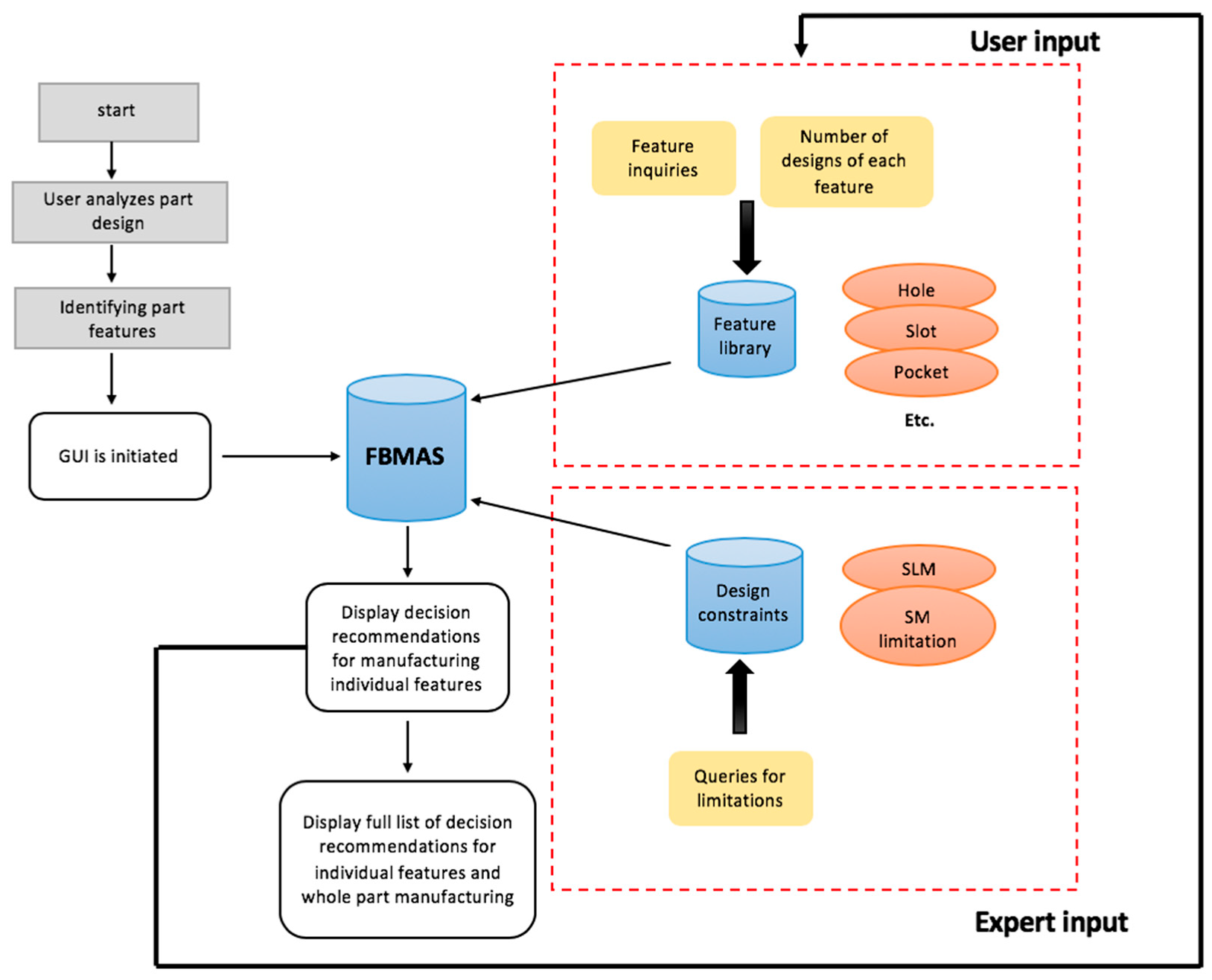
- Applying the feature-based system to assist users in defining and evaluating manufacturability limitations of a given tool insert based on a set of predetermined features criteria;
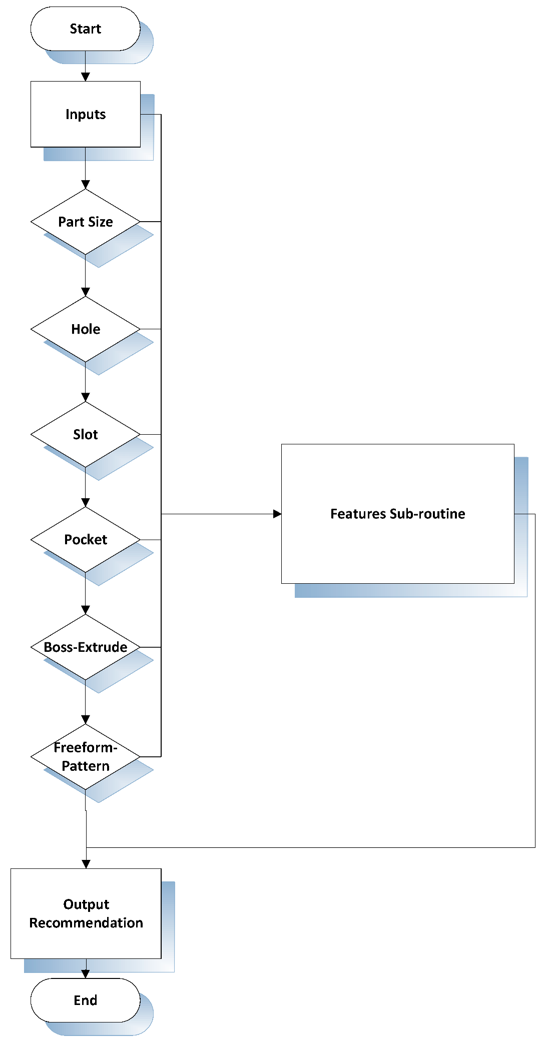
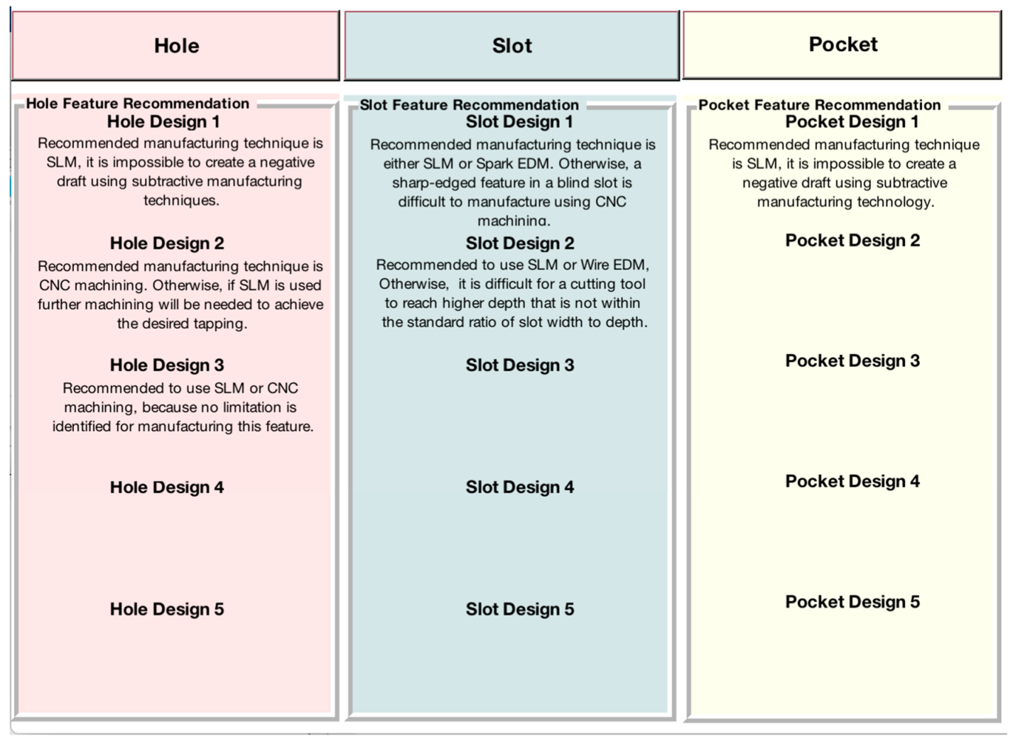
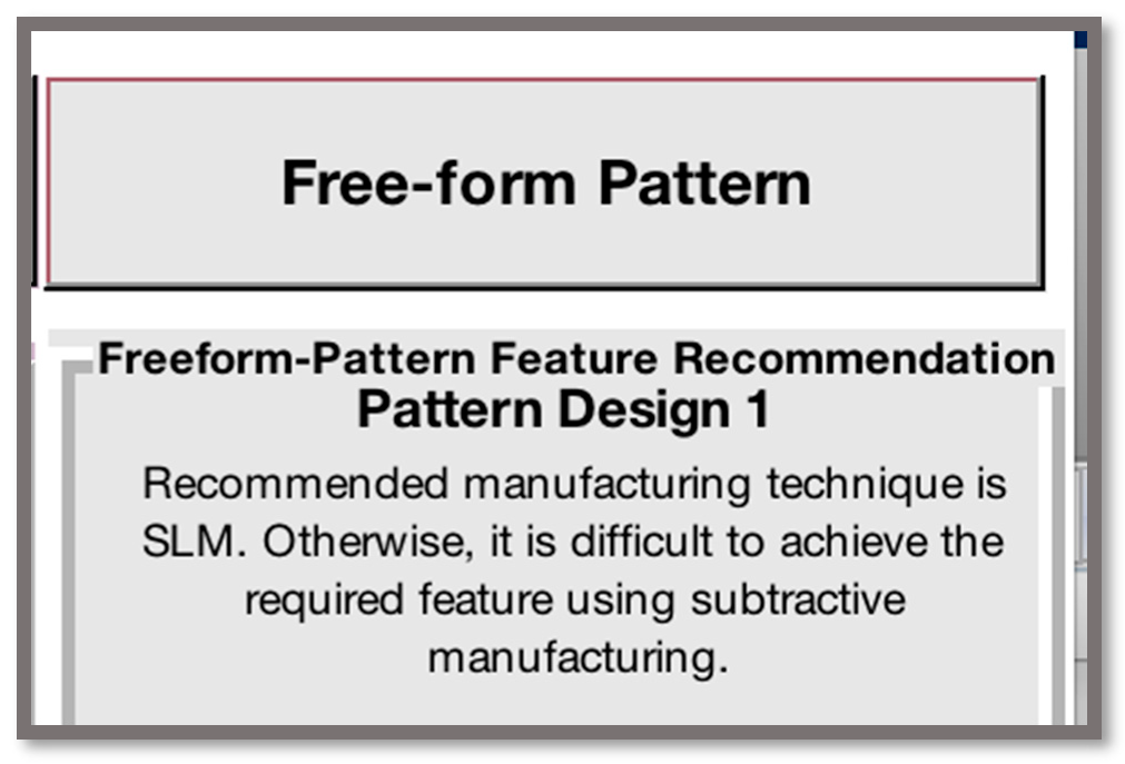
- The system is feature-based, evaluating the tool insert as multiple features and providing recommendations according to rules in the “IF-THEN” format that are constructed in the knowledge base. The “IF” part includes the condition clauses and the “THEN” part includes the resulting sentences;
- The separate feature recommendations are processed to provide the user with a generic part recommendation;
- The system is interactive in assisting the user to assess the feature-based manufacturability limitations and provide recommendations for which manufacturing technique to use.
- The only technologies that the FBMAS can be applied (i.e. will be limited) to are SLM for AM, CNC machining, die-sink electric discharge machining (EDM) and wire EDM for subtractive manufacturing;
- The rules set for the system were constructed on the basis of individualisation, with overlapping features being outside the scope of this research;
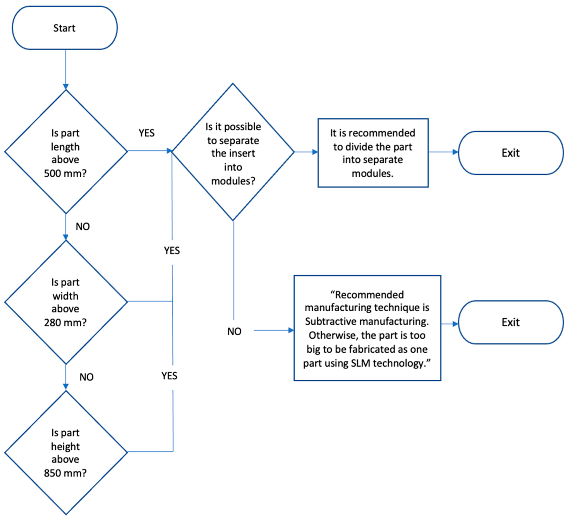
- The maximum part size allowed for this system is associated with the maximum volume of commercially acknowledged SLM machine systems (e.g., SLM Solutions [23]; 500 mm × 280 mm × 850 mm). The build platform wall allowance is understood based on technical user experience;
- The critical features identified for this study are limited to hole, slot, pocket, boss extrude, and freeform pattern (refer to Table 1);
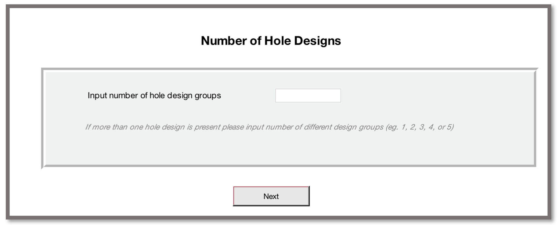
- The maximum number of designs of a feature allowed for this system is five designs—this rule applies to each of the features individually;
- Economic cost factors were disregarded in this research.
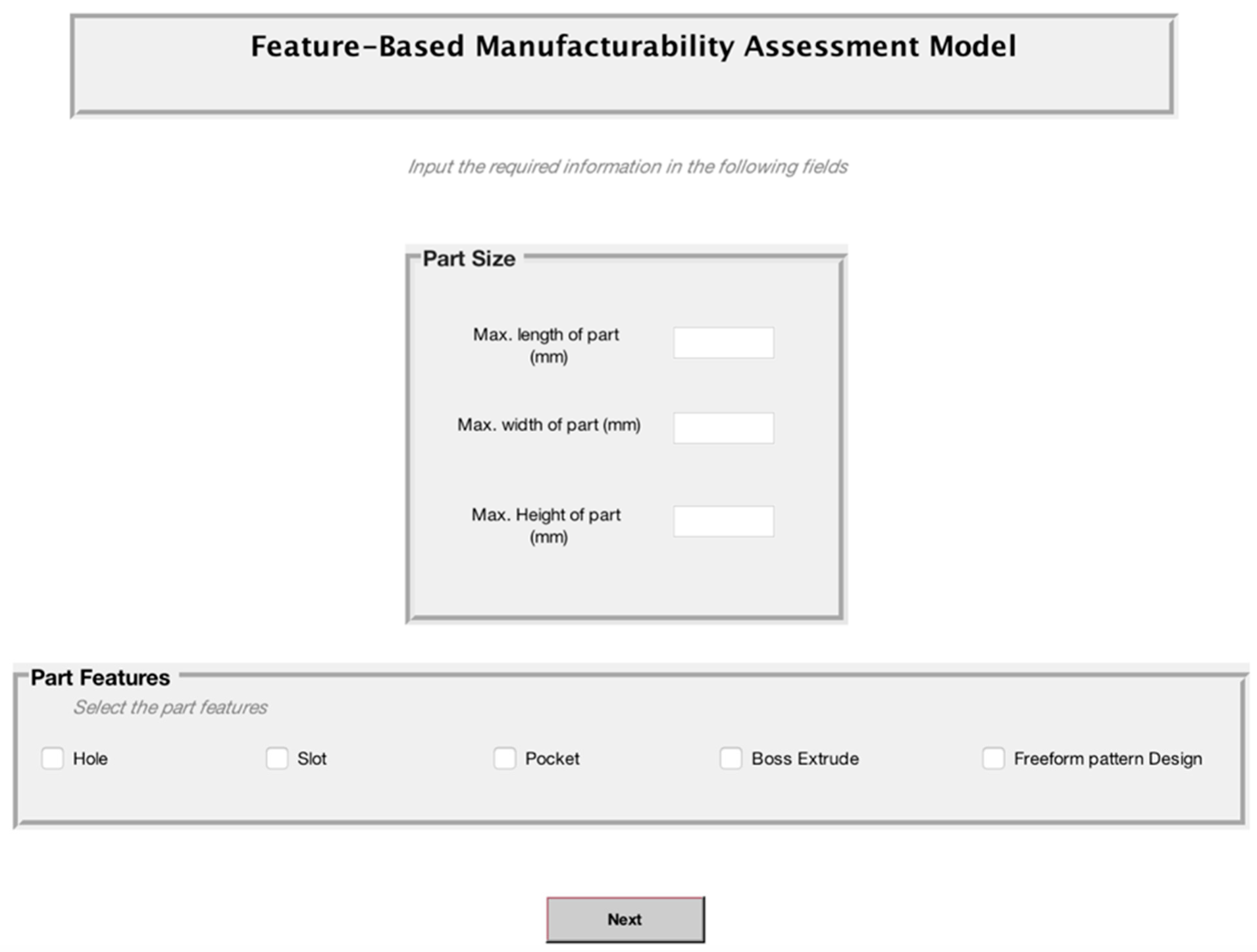
2.2. Graphical User Interface
2.2.1. FBMAS Main Initialisation
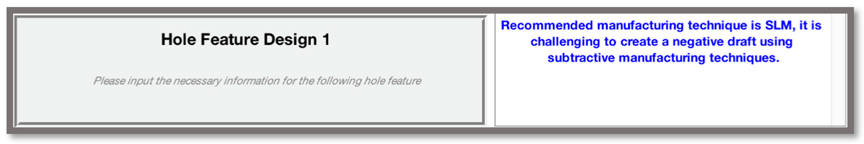
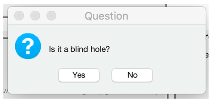
2.2.2. Design Features
2.2.3. Feature and Part Decision Recommendations
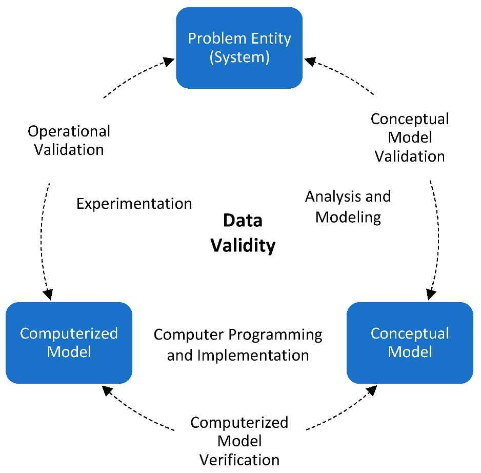
3. System Verification and Validation
3.1. System Verification
3.2. System Validation
4. Discussion
4.1. Manufacturability Assessment
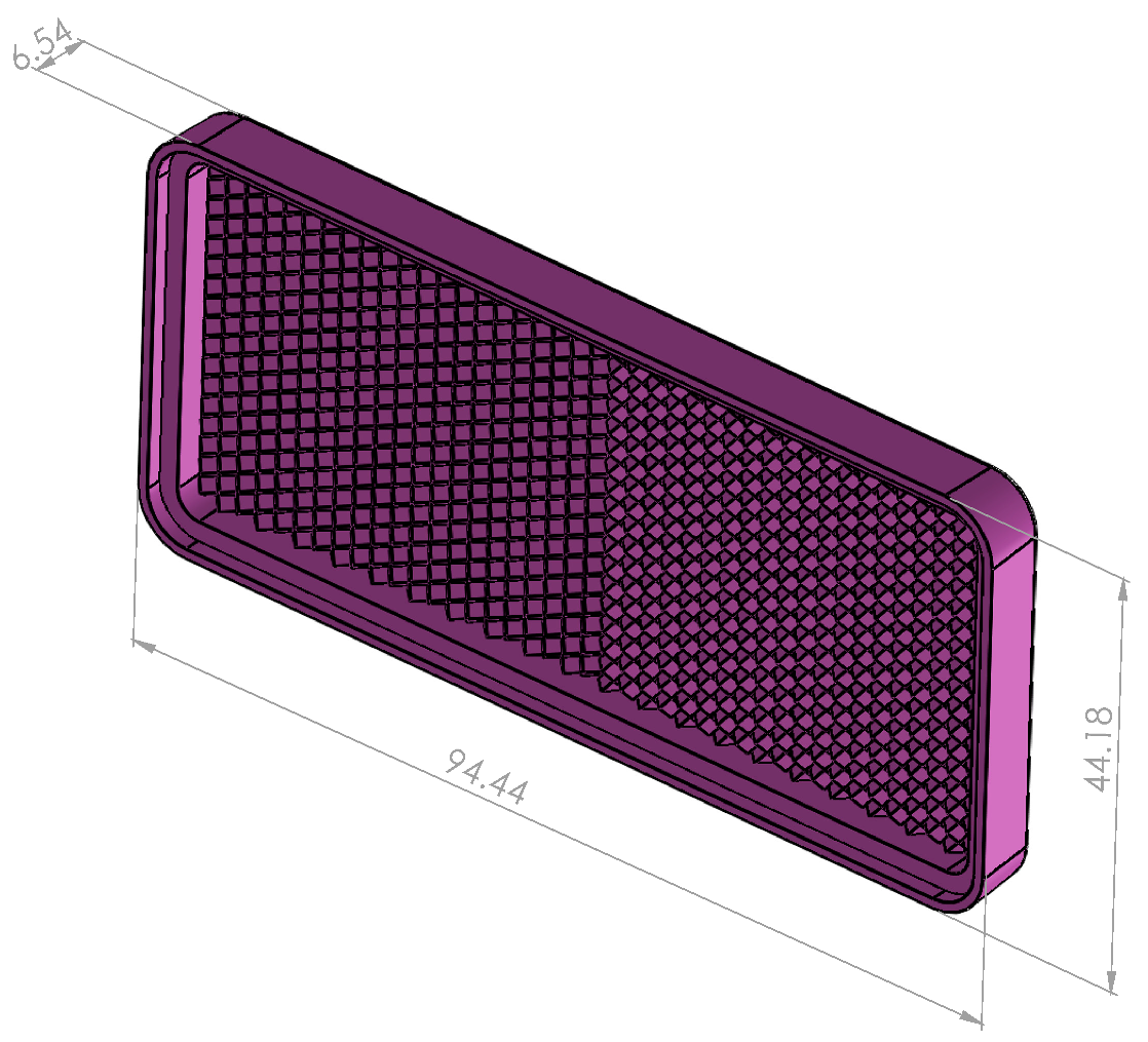
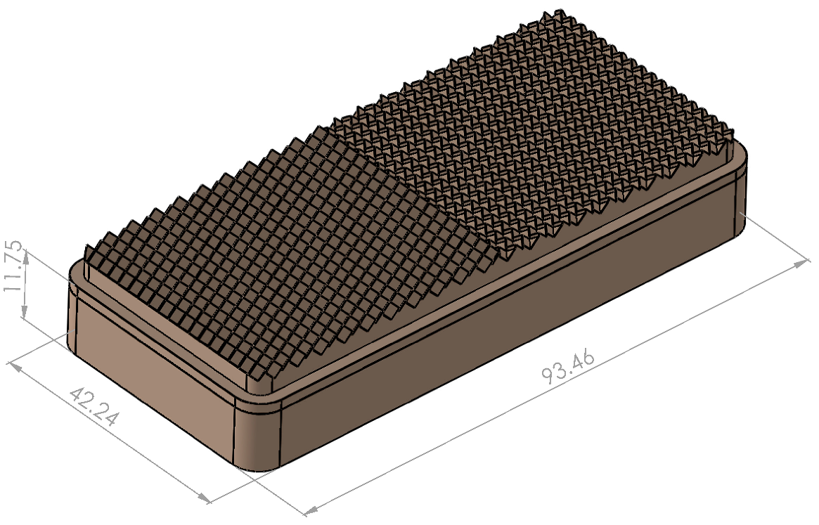
4.2. Core Insert Features Evaluation Using FBMAS
5. Conclusions
Author Contributions
Funding
Data Availability Statement
Acknowledgments
Conflicts of Interest
References
- Kumar, S.P.L. Knowledge-based expert system in manufacturing planning: State-of-the-art review. Int. J. Prod. Res. 2018, 57, 4766–4790. [Google Scholar] [CrossRef]
- Chen, Y.; Hsu, C.Y.; Liu, L.; Yang, S. Constructing a nutrition diagnosis expert system. Expert Syst. Appl. 2012, 39, 2132–2156. [Google Scholar] [CrossRef]
- Başak, H.; Gülesin, M. A feature based parametric design program and expert system for design. Math. Comput. Appl. 2004, 9, 359–370. [Google Scholar] [CrossRef]
- Pal, D.K.; Ravi, B.; Bhargava, L.S. Rapid tooling route selection for metal casting using QFD-ANP methodology. Int. J. Comput. Integr. Manuf. 2007, 20, 338–354. [Google Scholar] [CrossRef]
- Nagahanumaiah; Ravi, B.; Mukherjee, N.P. Rapid tooling manufacturability evaluation using fuzzy-AHP methodology. Int. J. Prod. Res. 2007, 45, 1161–1181. [Google Scholar] [CrossRef]
- Stavropoulos, P.; Tzimanis, K.; Souflas, T.; Bikas, H. Knowledge-based manufacturability assessment for optimization of additive manufacturing processes based on automated feature recognition from CAD models. Int. J. Adv. Manuf. Technol. 2022, 122, 993–1007. [Google Scholar] [CrossRef]
- Nagahanumaiah; Subburaj, K.; Ravi, B. Computer aided rapid tooling process selection and manufacturability evaluation for injection mold development. Comput. Ind. 2008, 59, 262–276. [Google Scholar] [CrossRef]
- Nagahanumaiah; Ravi, B. Effects of injection molding parameters on shrinkage and weight of plastic part—Produced by DMLS mold. Rapid Prototyp. J. 2009, 15, 179–186. [Google Scholar] [CrossRef]
- Kerbrat, O.; Mognol, P.; Hascoet, J.Y. Manufacturing complexity evaluation at the design stage for both machining and layered manufacturing. CIRP J. Manuf. Sci. Technol. 2010, 2, 208–215. [Google Scholar] [CrossRef]
- Townsend, V.; Urbanic, J. Relating additive and subtractive processes in a teleological and modular approach. Rapid Prototyp. J. 2012, 18, 324–338. [Google Scholar] [CrossRef]
- Ponche, R.; Kerbrat, O.; Mognol, P.; Hascoet, J.-Y.Y. A novel methodology of design for Additive Manufacturing applied to Additive Laser Manufacturing process. Robot. Comput. Integr. Manuf. 2014, 30, 389–398. [Google Scholar] [CrossRef]
- Zhang, Y.; Bernard, A.; Gupta, R.K.; Harik, R. Evaluating the Design for Additive Manufacturing: A Process Planning Perspective. Procedia CIRP 2014, 21, 144–150. [Google Scholar] [CrossRef]
- Sormaz, D.N.; Khoshnevis, B. Modeling of manufacturing feature interactions for automated process planning. J. Manuf. Syst. 2000, 19, 28–45. [Google Scholar] [CrossRef]
- Wang, L. An overview of function block enabled adaptive process planning for machining. J. Manuf. Syst. 2015, 35, 10–25. [Google Scholar] [CrossRef]
- Givehchi, M.; Haghighi, A.; Wang, L. Generic machining process sequencing through a revised enriched machining feature concept. J. Manuf. Syst. 2015, 37, 564–575. [Google Scholar] [CrossRef]
- Le, V.T.; Paris, H.; Mandil, G. Extracting features for manufacture of parts from existing components based on combining additive and subtractive technologies. Int. J. Interact. Des. Manuf. 2018, 12, 525–536. [Google Scholar] [CrossRef]
- Zhang, Y.; Bernard, A.; Gupta, R.K.; Harik, R. Feature based building orientation optimization for additive manufacturing. Rapid Prototyp. J. 2016, 22, 358–376. [Google Scholar] [CrossRef]
- LaCourse, D. What is Feature Detection Machining; MecSoft Corporation: Irvine, CA, USA, 2017. [Google Scholar]
- Thornton, V. Glossary of CAD Terms. In Material, Reference; Goodheart-Willcox Co., Inc.: Tinley Park, IL, USA, 2017. [Google Scholar]
- Solidworks Essential Manual; Dassault Systémes SolidWorks Corporation: Waltham, MA, USA, 2012; pp. 1–512.
- SECO. Catalog & Technical Guide 2019.2 Solid End Mills; SECO: Fagersta, Sweden, 2019. [Google Scholar]
- SECO. Catalog & Technical Guide 2019.2 Holemaking; SECO: Fagersta, Sweden, 2019. [Google Scholar]
- SLM Solutions Group. SLM 800—Large Format Selective Laser Melting; SLM Solutions Group: Lübeck, Germany, 2017. [Google Scholar]
- EPMA. Introduction to Additive Manufacturing Technology; EPMA: Chantilly, France, 2013. [Google Scholar]
- Renishaw PLC. Educational Article—Design for Metal AM—A Beginner’s Guide; Renishaw PLC: Gloucestershire, UK, 2017; Volume 44. [Google Scholar]
- Diegel, O.; Nordin, A.; Motte, D. Design for Metal AM; VTT Technical Research Centre of Finland Ltd.: Espoo, Finland, 2017. [Google Scholar]
- Drake, P.J., Jr. Dimensioning and Tolerancing Handbook; McGraw-Hill: New York, NY, USA, 1999. [Google Scholar]
- Henzold, G. Geometrical Dimensioning and Tolerancing for Design, Manufacturing and Inspection, 2nd ed.; Elsevier Ltd.: Amsterdam, The Netherlands, 2006; ISBN 0-7506-6738-9. [Google Scholar]
- Sargent, R.G. Advanced Tutorials: Verification and Validation of Simulation Models. In Proceedings of the 2011 Winter Simulation Conference, Phoenix, AZ, USA, 11–14 December 2011; pp. 183–198. [Google Scholar]
- El Kashouty, M.F. Development of a Novel Feature Based Manufacturability Assessment System for High-Volume Injection Moulding Tool Inserts. Ph.D. Thesis, Lancaster University, Lancaster, UK, 2020. [Google Scholar]
- Kashouty, M.F.E.; Rennie, A.E.W.; Ghazy, M.; Aziz, A.A.E. Selective laser melting for improving quality characteristics of a prism shaped topology injection mould tool insert for the automotive industry. Proc. Inst. Mech. Eng. Part C J. Mech. Eng. Sci. 2021, 235, 7021–7032. [Google Scholar] [CrossRef]


| Design Feature | Illustration | Definition |
|---|---|---|
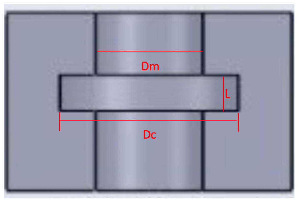
| Hole |  | A hole feature originates from a rounded profile. Hole types include ‘through’, ‘blind’, and ‘tapered’. |
| Slot |  | A slot is a perimeter that has a constant centre line and width. Slot types include ‘blind’, which are contoured with two ends, and ‘through’, which pass completely through the part. |
 | A pocket is a feature with an open or a closed perimeter often called an open pocket or a closed pocket. Pocket types include ‘through’ and ‘blind’. | |
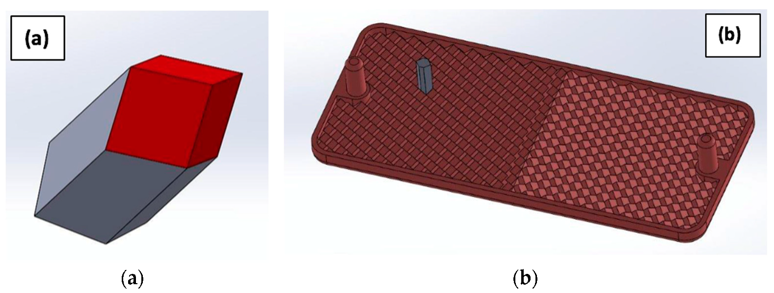
| Boss Extrude |  | A boss extrude feature adds to the area of the surface through extrudes above the planar surface. |
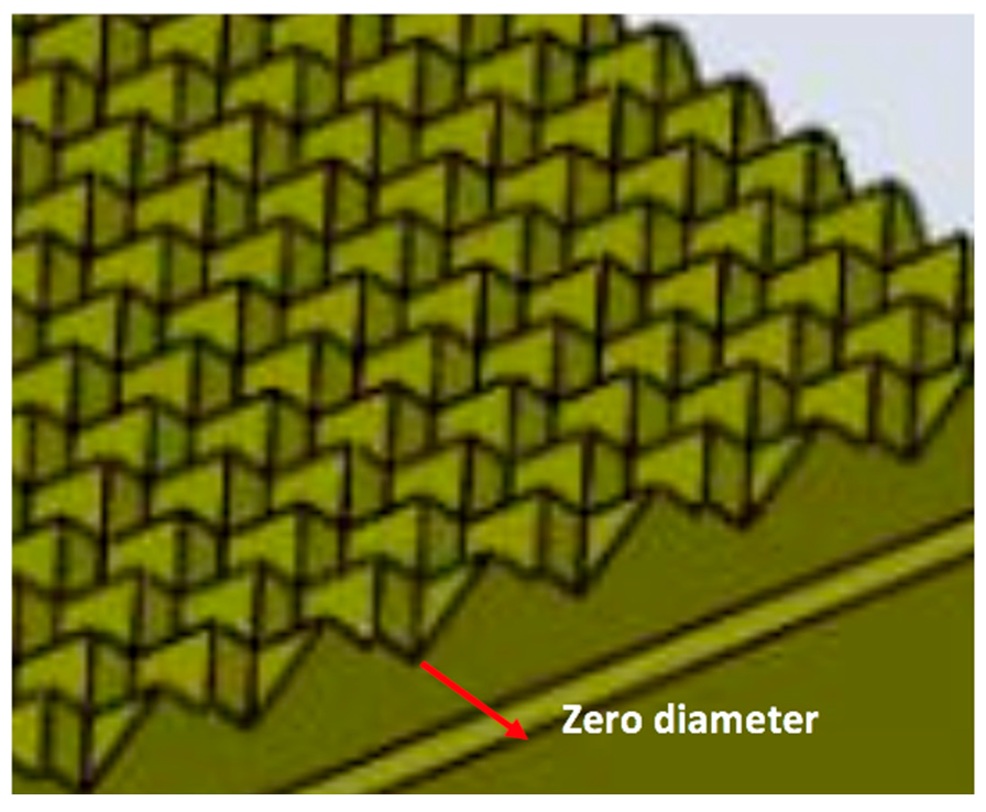
| Freeform Pattern |  | Any feature that has multiples that can be grouped together to create a pattern design. They can be machined as individual features or as a pattern. |
| Fillet |  | Fillets are rounded corners. A curve created at the intersection of two or more faces. |
| Sharp Edge |  | A sharp edge on the external side of a body. |
| Undercut |  | An undercut refers to a feature that is described as a non-visible recessed surface that is inaccessible using a straight tool. |
| Tapping |  | Tapping is responsible for creating screw threads in a hole. |
| Negative draft |  | In a part viewed from a plan view, the side walls are tapered towards the bottom; the internal dimension at the bottom has a larger dimension compared to the top. |
Disclaimer/Publisher’s Note: The statements, opinions and data contained in all publications are solely those of the individual author(s) and contributor(s) and not of MDPI and/or the editor(s). MDPI and/or the editor(s) disclaim responsibility for any injury to people or property resulting from any ideas, methods, instructions or products referred to in the content. |
© 2023 by the authors. Licensee MDPI, Basel, Switzerland. This article is an open access article distributed under the terms and conditions of the Creative Commons Attribution (CC BY) license (https://creativecommons.org/licenses/by/4.0/).
Share and Cite
El Kashouty, M.F.; Rennie, A.E.W.; Ghazy, M. A Novel Feature-Based Manufacturability Assessment System for Evaluating Selective Laser Melting and Subtractive Manufacturing Injection Moulding Tool Inserts. Designs 2023, 7, 68. https://doi.org/10.3390/designs7030068
El Kashouty MF, Rennie AEW, Ghazy M. A Novel Feature-Based Manufacturability Assessment System for Evaluating Selective Laser Melting and Subtractive Manufacturing Injection Moulding Tool Inserts. Designs. 2023; 7(3):68. https://doi.org/10.3390/designs7030068
Chicago/Turabian StyleEl Kashouty, Mennatallah F., Allan E. W. Rennie, and Mootaz Ghazy. 2023. "A Novel Feature-Based Manufacturability Assessment System for Evaluating Selective Laser Melting and Subtractive Manufacturing Injection Moulding Tool Inserts" Designs 7, no. 3: 68. https://doi.org/10.3390/designs7030068