Article

Control over Grid Reactive Power by Using a Powerful Regenerative Controlled-Speed Synchronous Motor Drive

by
Aleksandr S. Maklakov
1,*,
Aleksandr A. Nikolaev
2 and
Tatyana A. Lisovskaya
3
1
Project Activity Center, Scientific Activity Sector, Moscow Polytechnic University, 107023 Moscow, Russia
2
Research and Development Department, Nosov Magnitogorsk State Technical University, 455000 Magnitogorsk, Russia
3
Department of Automation and Control, Moscow Polytechnic University, 38 Bolshaya Semyonovskaya Street, 107023 Moscow, Russia
*
Author to whom correspondence should be addressed.
Designs 2023, 7(3), 62; https://doi.org/10.3390/designs7030062
Submission received: 11 April 2023 / Revised: 26 April 2023 / Accepted: 4 May 2023 / Published: 8 May 2023

Abstract

:
The authors propose a technique for reactive power compensation using a powerful regenerative controlled-speed synchronous motor drive (SMD) based on a three-level (3L) neutral point clamped (NPC) active front-end rectifier (AFE) and a voltage source inverter (VSI). The review of technical solutions for reactive power compensation showed that the limitations on the transmitted reactive power in the system under consideration still have not been studied. The paper provides a mathematical description and proposes synthesis-friendly block diagrams of the mathematical 3L-NPC-AFE-VSI and SMD models. The developed models allow defining the instantaneous values of the total 3L-NPC-AFE power consumed from the grid depending on the SMD load diagram. It is noted that the 3L-NPC-AFE-VSI-SMD system is designed without considering the opportunities for reactive power generation. It was determined that the limit value of reactive power generated by a 3L-NPC-AFE depends on the DC link voltage, the grid current consumption and the modulation index. The possibility of reactive power compensation by the SMD system through a 3L-NPC-AFE was experimentally tested on the main drive of a metal plate hot rolling mill. The analysis of the results obtained showed that during the breakdown, an SMD can generate reactive power equal to 16% of the total rated power using a 3L-NPC-AFE at a rated DC link voltage and without overcurrent. It was shown that generating reactive power is expedient in low-load SMD operation modes or at idle. Research in this area is promising due to the widespread use of high-power SMD based on a 3L-NPC-AFE-VSI and the tightening of requirements for energy saving and efficiency and supply voltage quality. The proposed reactive power control technique can be used as part of an industrial smart grid.

1. Introduction

The increase in the global demand for energy resources resulted in the emergence of new engineering systems based on power conversion equipment that can control large active and reactive power flows producing minimum adverse impacts on the environment and featuring high efficiency. Reactive power compensation technologies allow improving the energy quality and efficiency of various electrical complexes and systems. Most reactive power problems in the grid can be mitigated or solved with passive inductive or capacitive filters, static thyristors (STC) or synchronous reactive power compensators (STATCOM). However, this is expensive and may cause additional EMC problems.
Medium-voltage AC regenerative electric drives (AC RED), based on three-level neutral point clamped (3L-NPC) active front ends (AFE) and voltage source inverters (VSI), have similar opportunities to STATCOMs. These systems were widely introduced in metal plate rolling mills, excavators, electric trains, etc. [1,2,3]. Modern AC REDs have a number of advantages over the previous generation electric drives featuring thyristor rectifier modules, namely: (1) the capacity to regenerate the power to the grid in the generating modes of the electric drive with minimum distortion; (2) the capacity to adjust the cos(φ); and (3) the improved harmonic composition of the power consumed from the grid due to the use of specialized AFE pulse width modulation (PWM) algorithms [4,5]. Today, no full understanding has been formed of the reactive power compensation possibilities using high-power AC REDs with an AFE considering the possible limitations and associated problems. However, such modes are used ubiquitously and prove their efficiency.
Gonzalo Alonso Orcajo et al. [6,7,8] demonstrated the possibility of reactive power compensation in the grid via the modernization of several main electric drives of hot rolling mill stands. New electric drives feature three-level NPC AFE converters facilitating the electric motors’ consumption of active power to maintain the required rolling process and compensate for some of the reactive power consumed by neighboring devices. In terms of their practical significance, the solutions presented in the articles are straightforward and can be recommended for any other similar systems. However, these works do not cover in detail the issues of determining the possible limitations for reactive power compensation under the maximum current and voltage in the DC bus of the frequency converter. These problems require a deeper theoretical analysis to spread the suggested solutions to a wider class of objects.
In the article [9] by Pandit et al., an excavator power system was reviewed, with the power coefficient in the point of common connection (PCC) selected to provide the maximum reduction of voltage fluctuations on the high-voltage bushing of the excavator. To get the desired cos(φ), the high-power AC RED system used an AFE to compensate for the reactive power consumption from the auxiliary loads of the excavator. Note that this was achieved when the voltage in the DC link was two times higher than the voltage in the secondary winding of the transformer. This solution poses some questions about the operating conditions of the AC motor because the high voltage in the DC link has an adverse effect on the electromagnetic processes on the VSI side (low modulation index, higher harmonics, in-phase currents/voltages, etc.).
Brovanov et al. [10] provide a detailed analysis of electromagnetic processes occurring in the power circuit of a three-level converter with the NPC topology in autonomous electric power generation systems. As mentioned before, during the reactive power generation or consumption mode operation, the loads on the semiconductor converter modules become even more unequally distributed while the voltage in the DC link becomes more unbalanced, and the quality of converter power decreases insignificantly. However, these factors do not affect the converter operation if there is proper cooling provided, proper DC link voltage rectification algorithms are used, and proper sine filter parameters are selected.
This paper studies the possibilities and defines limitations in reactive power control using a powerful regenerative controlled-speed synchronous motor drive (SMD) based on a 3L-NPC-AFE. The paper has the following structure. Section 1 reviews the current research and formulates the study problem and objective. Section 2 covers the SMD model development for considering the load diagram impact on reactive power compensation modes. Section 3 analyzes vector diagrams of AFE operation modes. Section 4 gives the mathematical description of a 3L-NPC-AFE-VSI and analyzes the reactive power compensation mode. Section 5 provides the experimental study results. Finally, general conclusions are formulated.

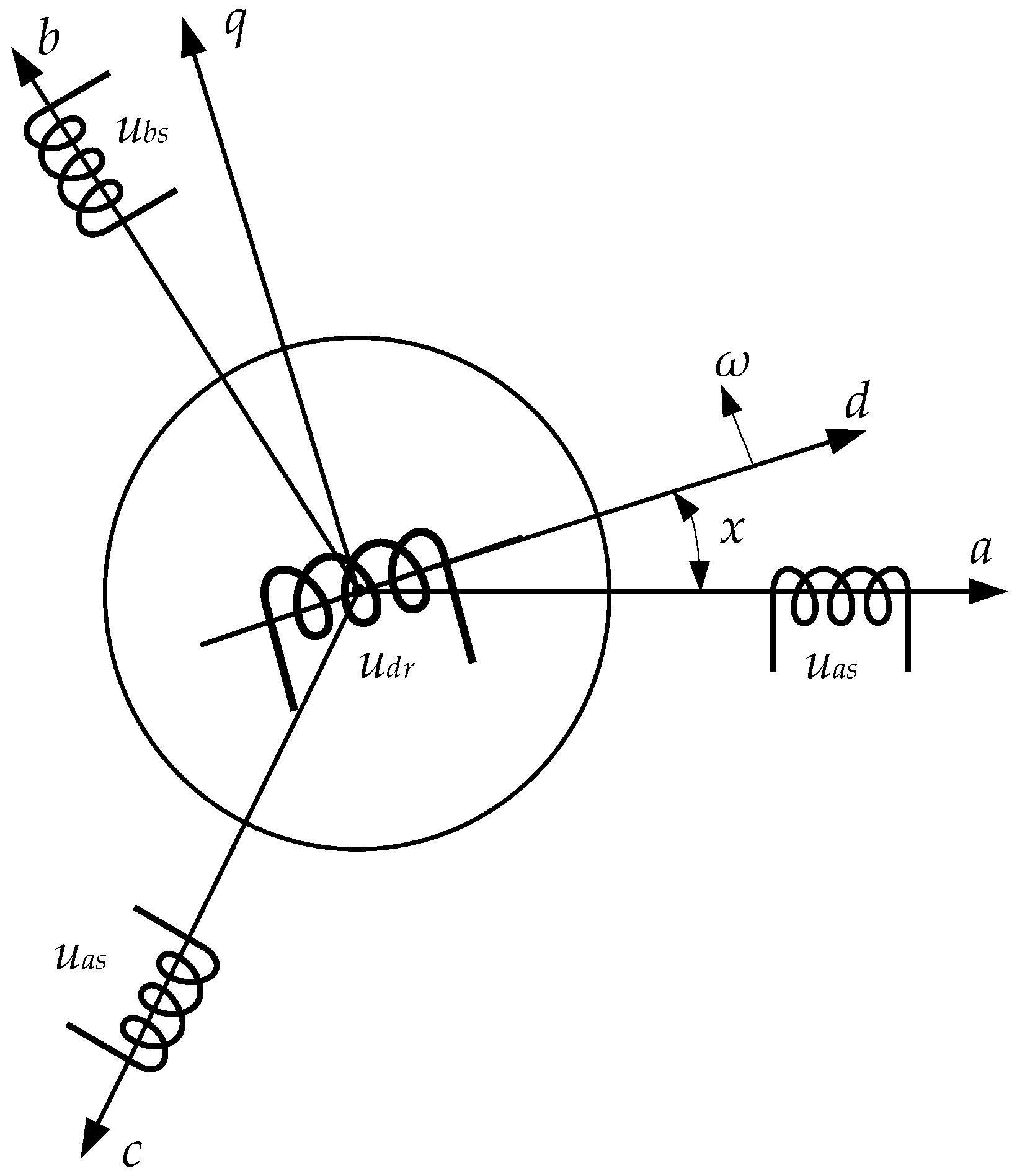
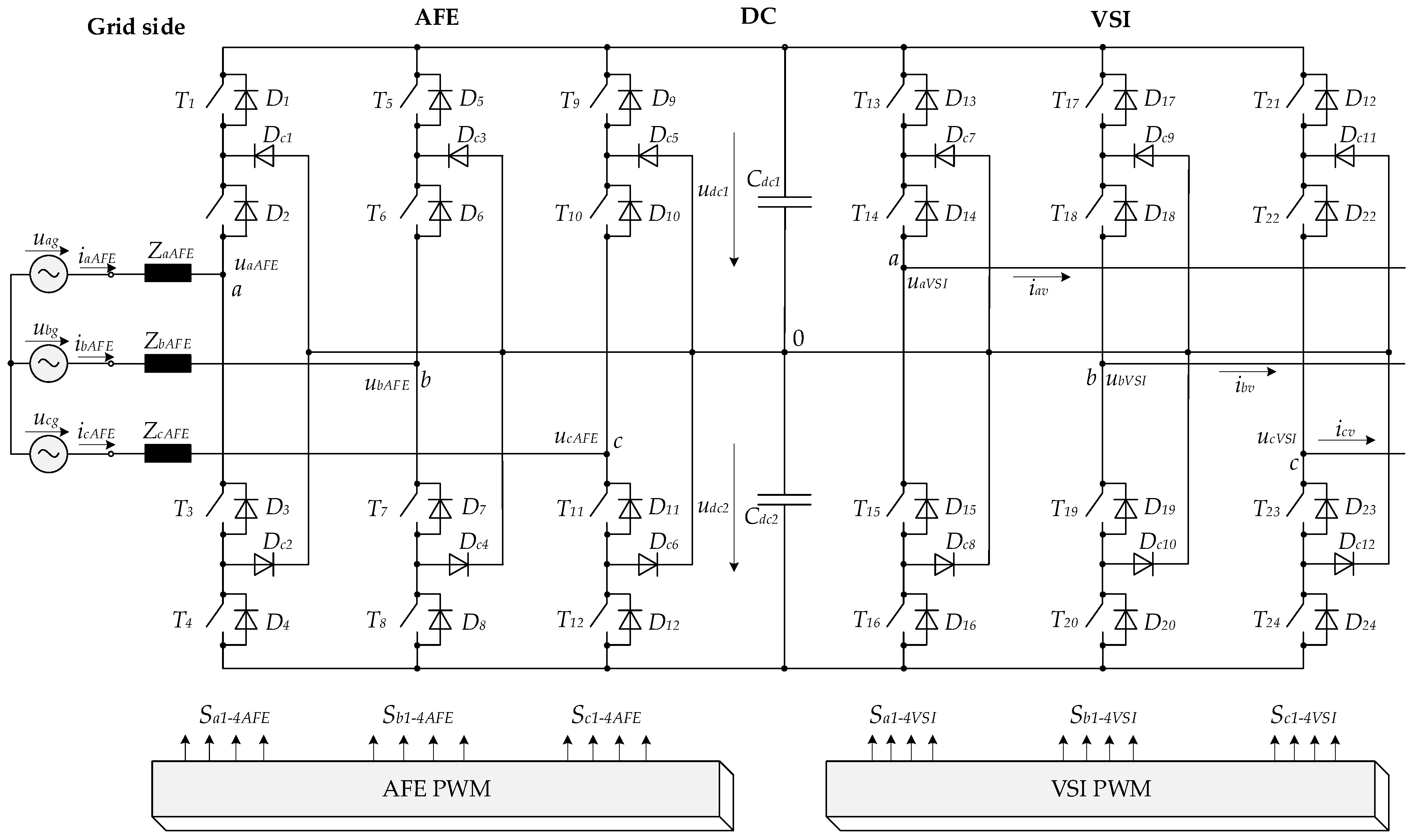
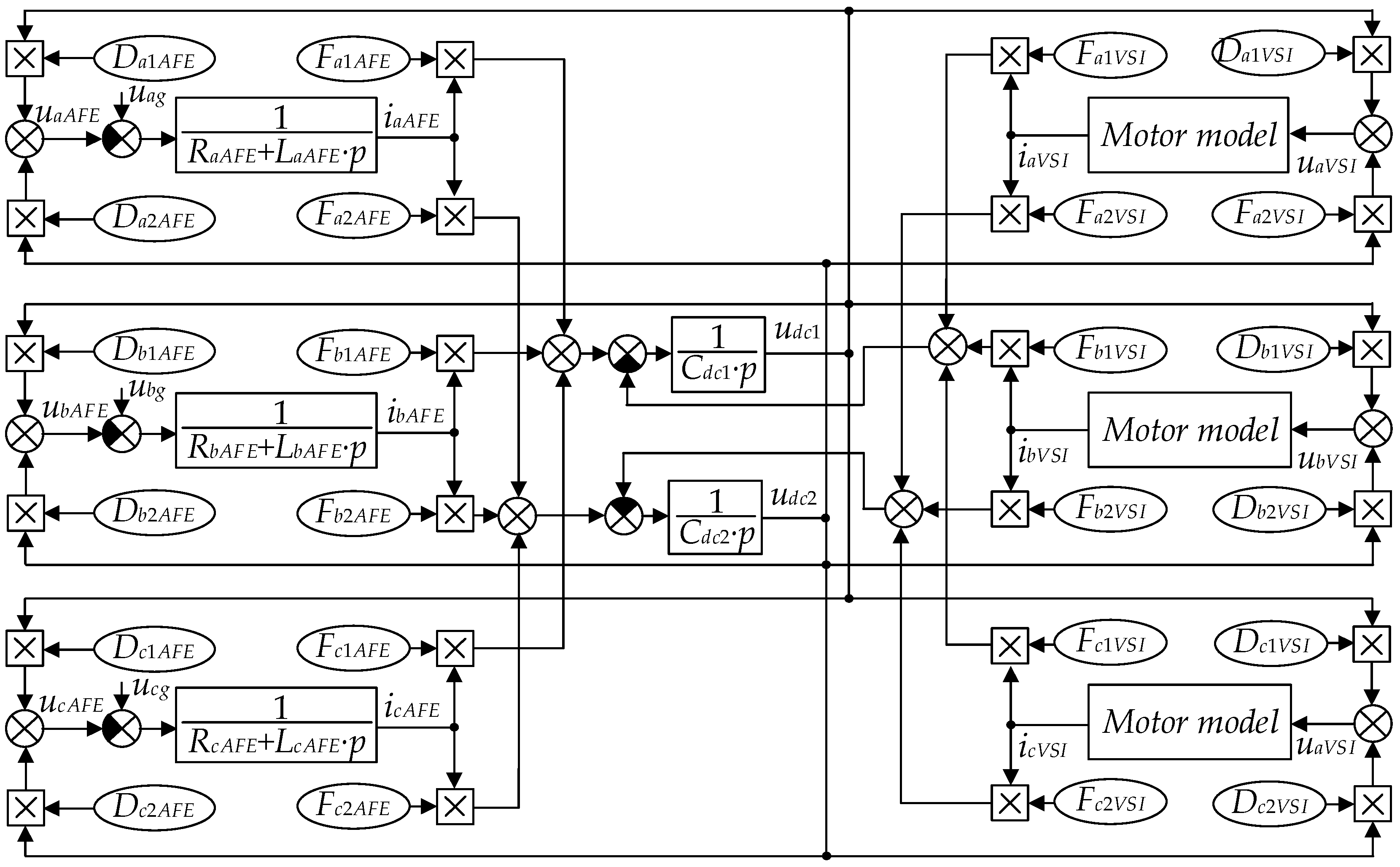
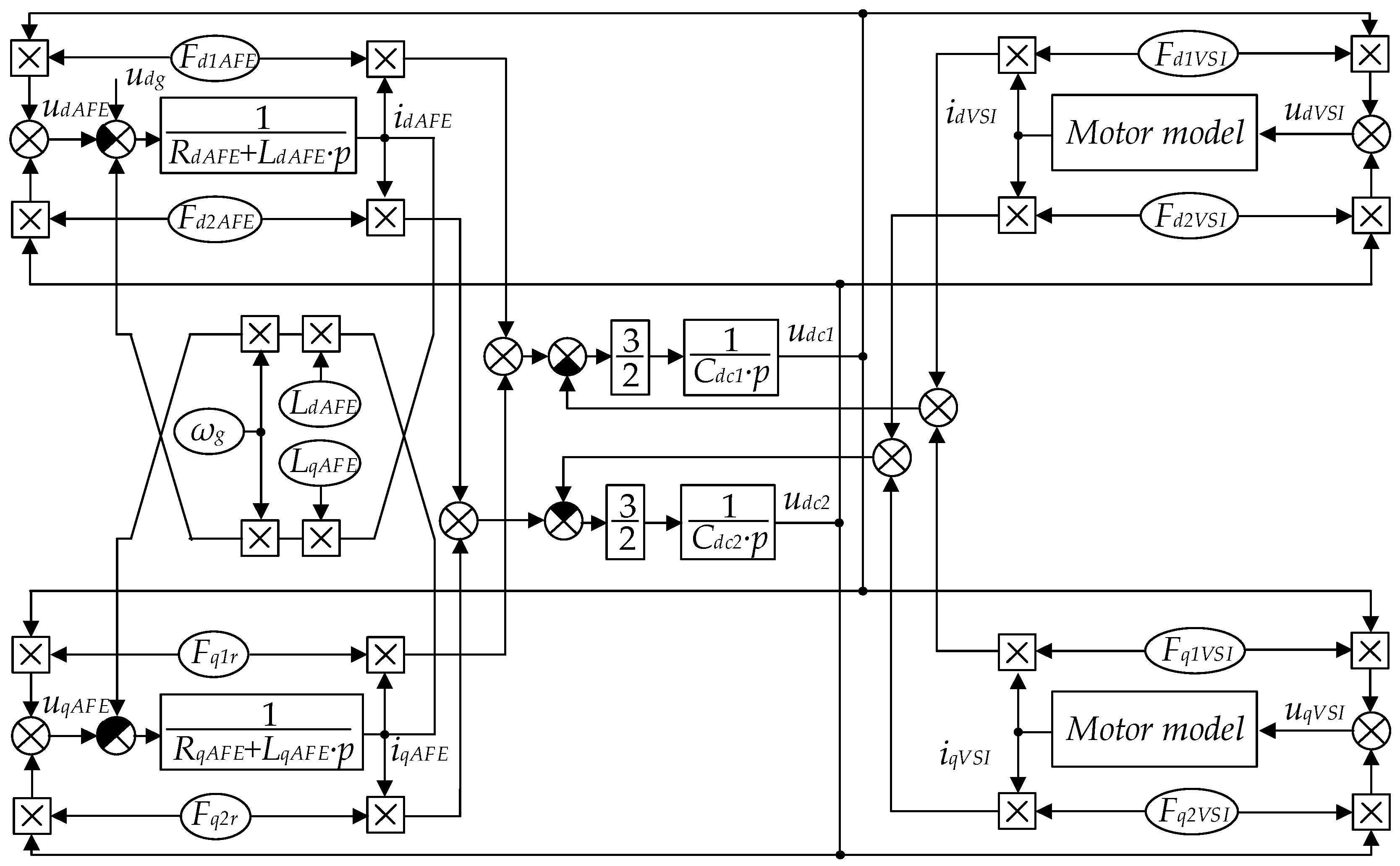
2. Developing a Mathematical Model of the SMD System

The SMD’s mathematical model is required to calculate the current consumption when operating in compliance with a process load diagram. The obtained data are used to form a disturbing effect in the DC voltage maintaining the circuit of the 3L-NPC-AFE control system.
All things considered, 3L-NPC-AFE-VSI-SMD systems are widely applied in the low-speed drives of metallurgical equipment characterized by increased requirements to the response, overload capacity and speed control quality, in wind turbines and traction drives, as well as in high-performance grinding units in the mining, cement and chemical industries. A simplified diagram of the SMD system is shown in Figure 1.
The decisive SMD advantages are the lack of power, overload capacity and current slew rate limitations, as well as the possibility of a significant improvement in dynamics by changing the synchronous motor design. SMDs are developed, as a rule, using custom-made high-torque synchronous motors. A high rate of electromagnetic use is decisive for developing their control systems, which predetermined high requirements for the response of the internal stator current control loops [11].
The equivalent circuit of a synchronous machine is derived from a generalized AC machine; the stator and rotor windings are fed with AC and DC, respectively. In the steady state, the rotor rotates simultaneously with the field in the air gap. A diagram of the SM model for mathematical derivations is presented in Figure 2.
As a rule, rotors have a single excitation winding along the longitudinal axis. In some cases, one observes the use of compensated SMs containing an additional transverse excitation winding. In a frequency-controlled drive, this winding is not required; moreover, it has an adverse effect, making it difficult to boost transients. Therefore, it is further assumed that the rotor has a single longitudinal excitation winding. Furthermore, the SM is assumed to be laminated, so the impact of eddy currents in the massive core parts can be neglected. The voltage equilibrium equation for the stator windings is as follows:
u s = R s i s + d d t ψ s
where u s = u s a u s b u s c is the stator voltage; i s = i s a i s b i s c is the stator current.
The stator flux linkages are as follows:
ψ s = L s s i s + M s r i f
where if is the excitation winding current.
The stator inductance matrix is expressed as follows:
L s s = L a a L a b L a c L b a L b b L b c L c a L c b L c c = L a v e + L m cos 2 x M a v e + L m cos ( 2 x 2 π 3 ) M a v e + L m cos ( 2 x + 2 π 3 ) M a v e + L m cos ( 2 x 2 π 3 ) L a v e + L m cos ( 2 x + 2 π 3 ) M a v e + L m cos 2 x M a v e + L m cos ( 2 x + 2 π 3 ) M a v e + L m cos 2 x L a v e + L m cos ( 2 x 2 π 3 )
where Lave and Mave are the average values of the self-inductance of the stator phase and the mutual inductance between two stator phases.
The matrix of mutual inductances of the stator phase and the excitation winding is as follows:
M s r = L a f L b f L c f = M f cos x M f cos ( x 2 π 3 ) M f cos ( x + 2 π 3 )
The flux linkage of the excitation winding is as follows:
ψ f = M f cos x M f cos ( x 2 π 3 ) M f cos ( x + 2 π 3 ) i s + L f f i f
where Lff is the self-inductance of the excitation winding; Mf is the maximum mutual inductance between the excitation winding and the stator phase.
Due to the synchronous (magnetic and electric) machine rotor asymmetry, equations with constant coefficients can only be obtained when transformations are conducted in the dq0 reference frame, the axes of which are rigidly connected to the rotor. The matrix of this transformation for the stator equation is as follows:
A s = 2 3 cos x cos ( x 2 π 3 ) cos ( 2 x + 2 π 3 ) sin x sin ( x 2 π 3 ) sin ( x + 2 π 3 ) 1 2 1 2 1 2
The formulas for transforming stator currents into the dq0 axis components obtained from the equation i d q 0 = A s i s , have the following form:
{ i d = 2 3 ( i s a cos x + i s b cos ( x 2 π 3 ) + i s c cos ( x + 2 π 3 ) ) ; i q = 2 3 ( i s a sin x + i s b sin ( x 2 π 3 ) + i s c sin ( x + 2 π 3 ) ) ; i 0 = 1 3 ( i s a + i s b + i s c ) .
Both parts of Equation (1) are multiplied by the As matrix on the left to obtain, in the expanded form, the following:
u d = i d R s + d ψ d d t + ω ψ q ; u q = i q R s + d ψ q d t + ω ψ d ; u 0 = i 0 R s + d ψ s 0 d t .
A similar operation conducted with Equation (2) gives the following equations for the stator flux linkages:
ψ d = i d L d + i f M f ; ψ q = i q L q ; ψ s 0 = i 0 L 0 ,
where L d = L a v e + M a v e + 3 2 L m ;   L q = L a v e + M a v e 3 2 L m ;   L 0 = L a v e 2 M a v e .
Considering the first Equation (7), the excitation winding flux linkage Equation (5) can be represented as follows:
ψ f = 3 2 i d M f + i f L f f .
The rotor winding equation is as follows:
u f = i f R f + d ψ f d t .
The SM electromagnetic torque is expressed as follows:
M = 3 2 Z p ( ψ d i q ψ q i d ) .
The rotor motion equation is as follows:
M M s = J Z p d ω d t ,
where J is mass moment of inertia; Zp is a pair of poles.
Equations (8)–(13) form a complete system of equations for a synchronous machine. It can be transformed into a form suitable for the synthesis of an automated control system. Considering Equations (10) and (11), the following is obtained:
u f = i f R f + L f f d i f d t + 3 2 M f d i d d t ,
from which, d i f d t = 1 L f f ( u f + i f R f 3 2 M f d i d d t ) .
From Equations (8) and (9), we obtain the following:
u d = i d R s + L d d i d d t ω L q i q + M f d i f d t .
Substituting Equation (14) into Equation (15) and considering that d/dt = p, we obtain the following:
u d = R s ( 1 + p T s d ) i d + K f U f K f R f i f ω ψ q ,
where T s d = L d R s ;   L d = L d 3 M f 2 2 L f f ;   K f = M f L f f .
From Equations (8) and (9), we obtain the following:
u q = R s ( 1 + p T s q ) i q + ω ψ d ;
where T s q = L q R s .
From Equations (9) and (14), we obtain the following:
u f = R f ( 1 + p T d 0 ) i f + K d p ψ d ,
where T d 0 = L f R f ;   L f = L f f 3 M f 2 2 L d ;   K d = 3 M f 2 L d .
The vector–matrix system of equations is synthesized based on the SM block diagram with the main controlled coordinates id, iq and ψf.
From Equation (11), considering Equation (10), we obtain the following:
u f = 1 + p T d o T d o ψ f 3 2 K f R f i d ,
where T d o = L f f R f .
In this case, the longitudinal stator flux linkage can be represented as follows:
ψ d = i d L d + K f ψ f .
The block diagram with the main controlled coordinates id, iq and ψf was built using Equations (9), (12), (13) and (16)–(20) and is shown in Figure 3. This diagram is convenient for the synthesis of a vector control system.
The SM control algorithm in the reference frame associated with the rotor and the main conditions for implementing it can be formulated if we assume that the stator windings are powered by a VSI operating in the AC power source mode.
The requirements for the optimal use of the SM power-to-size ratio and the installed capacity of the 3L-NPC-AFE-VSI necessitate meeting the following conditions:
  • Providing the SM operation with a rated stator flux linkage within the entire load change and speed control range (except for the field weakening mode with two-zone control):
    ψ s r e f ψ s r a t e
  • Providing the SM operation with a power factor equal to (or close to) unity:
    Q s = 3 2 ( ψ d i d + ψ q i q ) = 0 .
Based on Equations (21) and (22), the synchronous motor’s electromagnetic torque is determined as follows:
M = 3 2 Z p ψ s r a t e i s .
When conditions (21)–(23) are fulfilled, the stator’s full flux linkage vector is always perpendicular to the I ~ s vector, i.e., Re ( ψ ~ s * I ~ s ) = 0 . Since the SM’s electromagnetic torque is always proportional to the stator and rotor flux linkages, this solves the problem of optimal use of its power-to-size ratio. For vector control of a synchronous motor using Equation (23), the following dependencies were obtained:
i d = L q ψ s 1 + M 2 ( 3 2 Z p ψ s ) 2 L q 2 ψ s 2 M 2 ( 3 2 Z p ψ s ) 2
i q = L q 1 + M 2 ( 3 2 Z p ψ s ) 2 L q 2 ψ s 2 M 3 2 Z p ψ s
ψ f = 1 1 + M 2 ( 3 2 Z p ψ s ) 2 L q 2 ψ s 2 [ L f f I f 0 + L d L q K f ψ s M 2 ( 3 2 Z p ψ s ) 2 ]
where I f 0 is the excitation current according to the no-load characteristic.
Figure 1 shows the block diagram of a closed-loop control system. The controllers are synthesized in the dq0 coordinate system: the speed control loop with a PI controller is an outer control loop, and the control loops of the stator current components id and iq and the rotor winding flux linkage ψf are the inner control loops. The three aforementioned loops in the aggregate make a multidimensional torque loop. The drive signals at the input of the control loops of the longitudinal and transverse components of the stator currents and the flux linkage of the excitation winding are implemented according to function Equations (24)–(26). With a high response of the internal control loops, the function equations compensate for the nonlinearities of the SM’s control object in the reference frame selected.
Figure 1 shows the compensators of the two main crosslinks for rotational EMF. When choosing the stator current components id and iq and the excitation winding flux linkage ψf as the controlled variables, only these internal crosslinks require compensation. The crosslinks between the excitation and longitudinal component circuits are very weak. The compensation of the main SM crosslinks and nonlinearities is achieved by almost full decoupling of the id, iq and ψf control loops. Controllers are implemented as active filters. To eliminate the static control error, current PI controllers are used in the dq0 reference frame.
Thus, the 3L-NPC-AFE-VSI-SMD is developed on the basis of the conditions stipulated for the optimal use of the SM and frequency converter powers; thus, the reactive power generation mode will be limited by active power consumption. Therefore, the 3L-NPC-AFE operation opportunities and limitations for the reactive power generation in various drive operation modes should be analyzed in more detail.

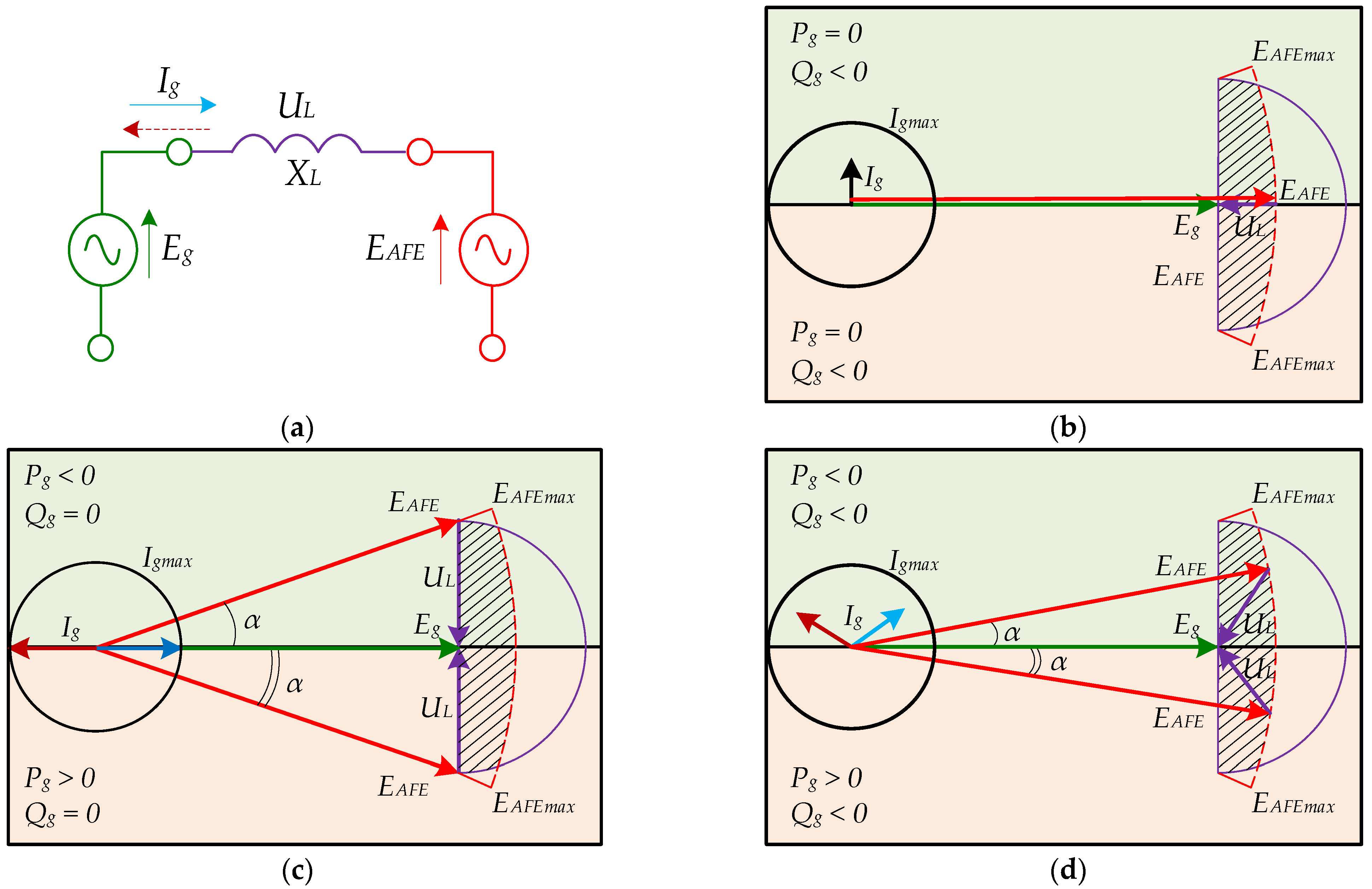
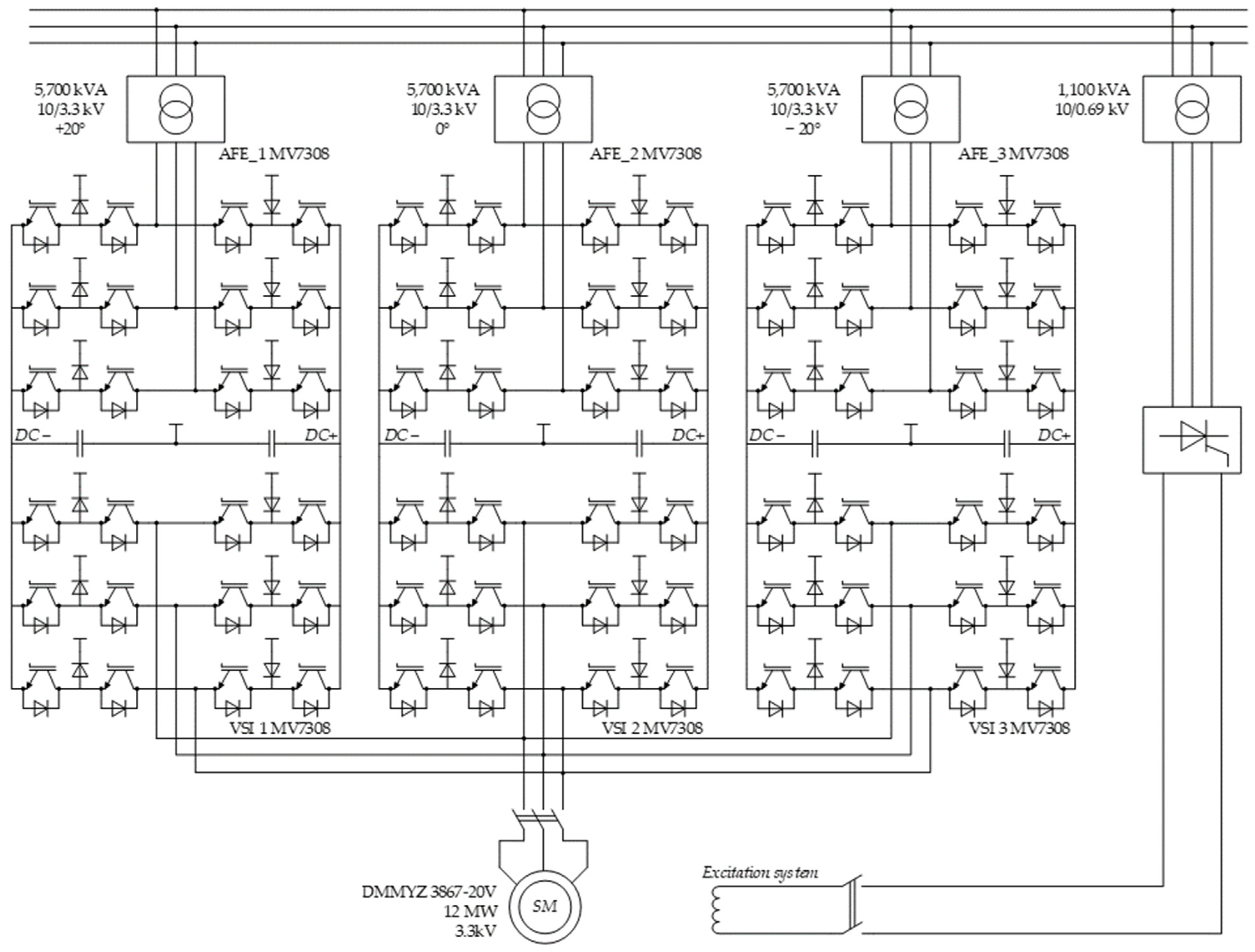
3. AFE Power Description

The possibilities of reactive power compensation within the system of an AFE and the grid can be conveniently reviewed using a single-phase equivalent circuit shown in Figure 4a. The system is shown as the EMF of the AFE EAFE connected over the reduced inductive reactance XL at the terminal point of the secondary transformer winding EMF (grid) Eg. The difference between EAFE and Eg corresponds to XL, the voltage drop for which is UL. Further, review of the AFE operation using vector diagrams in Figure 4b–d features marked limitations for the maximum current Igmax and AFE EMF EAFEmax. Accounting for these limitations allowed obtaining the acceptable AFE operation range, which is crosshatched with black lines in Figure 3.
Figure 4b shows the positioning of the vectors during the AFE operation in the reactive power generation mode (similar to a static VAR compensator). This mode is possible during idling operation. Note that in this mode, the maximum reactive current value is severely limited as the ceilings of EAFE are also limited by EAFEmax. It is possible to increase the generated reactive power through the additional charging of the capacitors in the DC link.
In the lower region of Figure 4c, the AFE operates in the rectifier mode. Current Ig consumed from the grid is in phase with grid voltage Eg, which results in a single power coefficient at the converter input. This mode requires adjusting the amplitude and phase of the EAFE converter voltage relative to Eg so that the voltage drop over the reduced inductance UL is perpendicular to Eg. In the upper region of Figure 4c, the AFE operates in the inverter mode. Vector Ig is opposite in phase to vector Eg, which also results in a single power coefficient at the converter input. For this mode, the EAFE voltage phase must outrun voltage Eg by angle α. In the reviewed modes, the AFE can operate at maximum current Igmax. They can be used to determine the possible reactive power generation region.
In the lower region of Figure 4d, the AFE operates in the rectifier mode, and in the upper region of Figure 4d, it operates in the inverter mode with reactive power generation. For them, the voltage drop UL is not perpendicular to Eg, which results in current Ig outrunning or lagging behind Eg. The analysis of the diagram shows that the generated reactive power can also be increased using the additional charging of the capacitors in the DC link. However, it is necessary to account for the consumed active power to prevent the tripping of the maximum permissible AFE current.
The analysis of the vector diagrams of AFE operation in Figure 4 shows that it is possible to compensate for the reactive power both in the motoring and inverter operation modes.
Taking into account an equivalent active resistance R at the common coupling point, the equations for the calculation of active, reactive and apparent power can be composed as follows:
P g = E g E A F E ( R cos ( α ) + X L sin ( α ) ) E g 2 R R 2 + X L 2 ,
Q g = E g E A F E ( X L cos ( α ) + R sin ( α ) ) E g 2 X L R 2 + X L 2 ,
S g = E g 2 ( E A F E 2 2 E g E A F E cos ( α ) + E g 2 ) R 2 + X L 2 .
where Pg, Qg and Sg are the dependencies of the active, reactive and apparent powers of the grid and α is the shift angle between Eg and EAFE.
When AFEs operate in the PWM mode, the maximum amplitude of the continuous (useful) component of the phase voltage EAFEmax is determined by the Udc value and the PWM algorithm. Controlled AFE operation requires the voltage in the Udcmin DC link to be at such a minimum level that allows for blocking of the forward diodes. Thus, the DC link voltage should be higher than the grid voltage amplitude value, considering the voltage drop across the active inductive input impedance.
It is known that six-step control is the best option for the DC link voltage. Currently, for most AFEs as part of an SMD, PWM with selected harmonic elimination (SHE) is used to provide the best quality of converted voltage under the low semiconductor module’s switching frequency [11,12,13,14,15]. Along with good electromagnetic compatibility, PWM with SHE facilitates the use of the DC link voltage at the six-step modulation level (KPWM ≈ 2/π) [16,17,18]. The EAFE vector length is controlled using the modulation index m, which is calculated as follows:
m = π E A F E 2 U d c
To define the limit EAFEmax value, the following equation is used:
E A F E max = U d c K P W M = 2 π U d c
At different m values, the converted power quality parameters change. The relevant studies in the area have shown that the higher the m value, the lower the THD of the converter output voltage [19,20,21,22,23]. In practice, the m value close to 1 (if we describe a range from 0 to 4/π) is chosen while providing a margin for maintaining stable AFE and VSI operation in dynamic modes (a voltage drop in the DC link during shock application of the electric drive load) [24,25,26,27].
Considering the aforementioned Equations (30) and (31), the active, reactive and apparent powers can be determined as follows:
P g = E g m U d c 2 π ( R cos ( α ) + X L sin ( α ) ) E g 2 R R 2 + X L 2 ,
Q g = E g m U d c 2 π ( X L cos ( α ) + R sin ( α ) ) E g 2 X L R 2 + X L 2 ,
S g = E g 2 ( ( m U d c 2 π ) 2 2 E g m U d c 2 π cos ( α ) + E g 2 ) R 2 + X L 2 .
Based on Equations (32)–(34), the limit values of the active, reactive and apparent powers at the set values of the grid voltage and equivalent active inductive impedance on the AFE side can be controlled by the modulation index, the DC link voltage and the shift angle α. The problem of generating reactive power in the system under consideration is solved using an AFE control system.

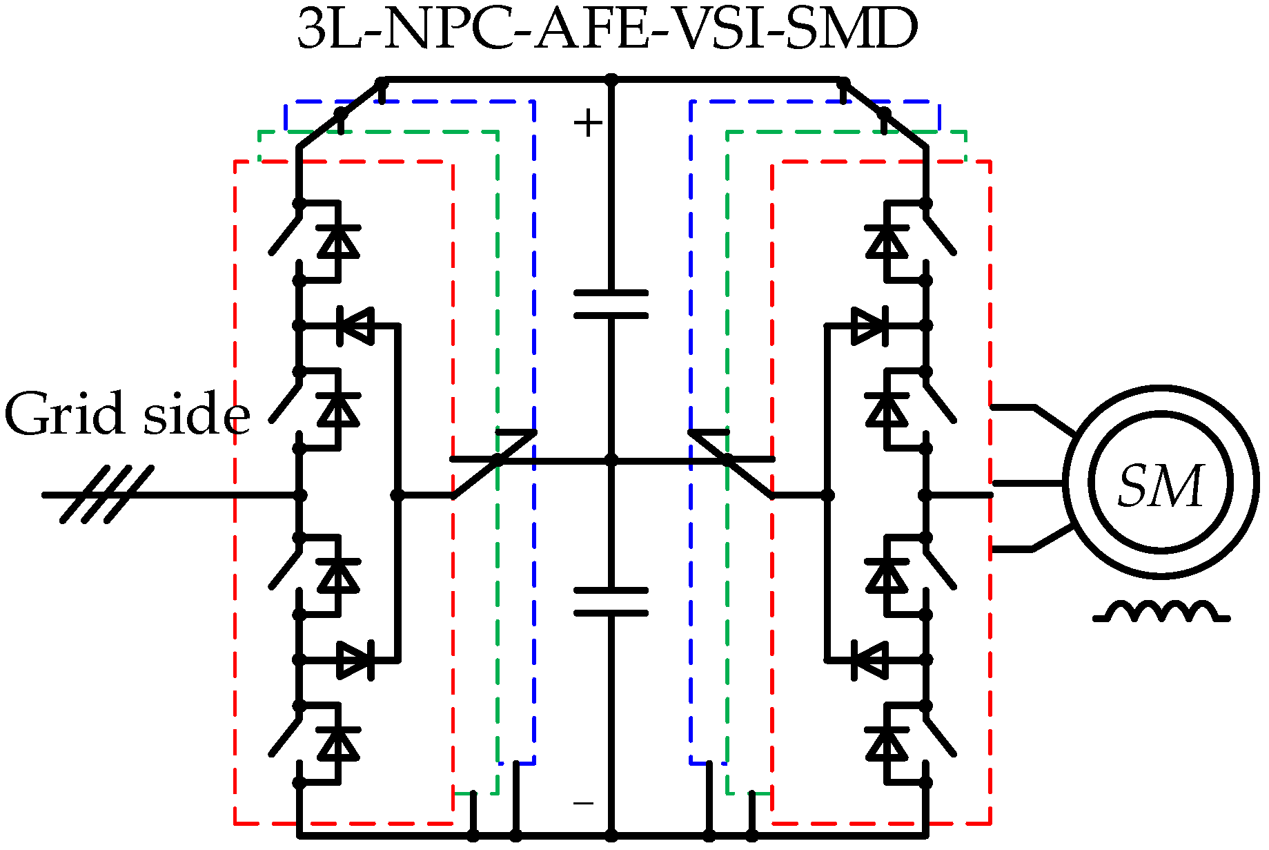
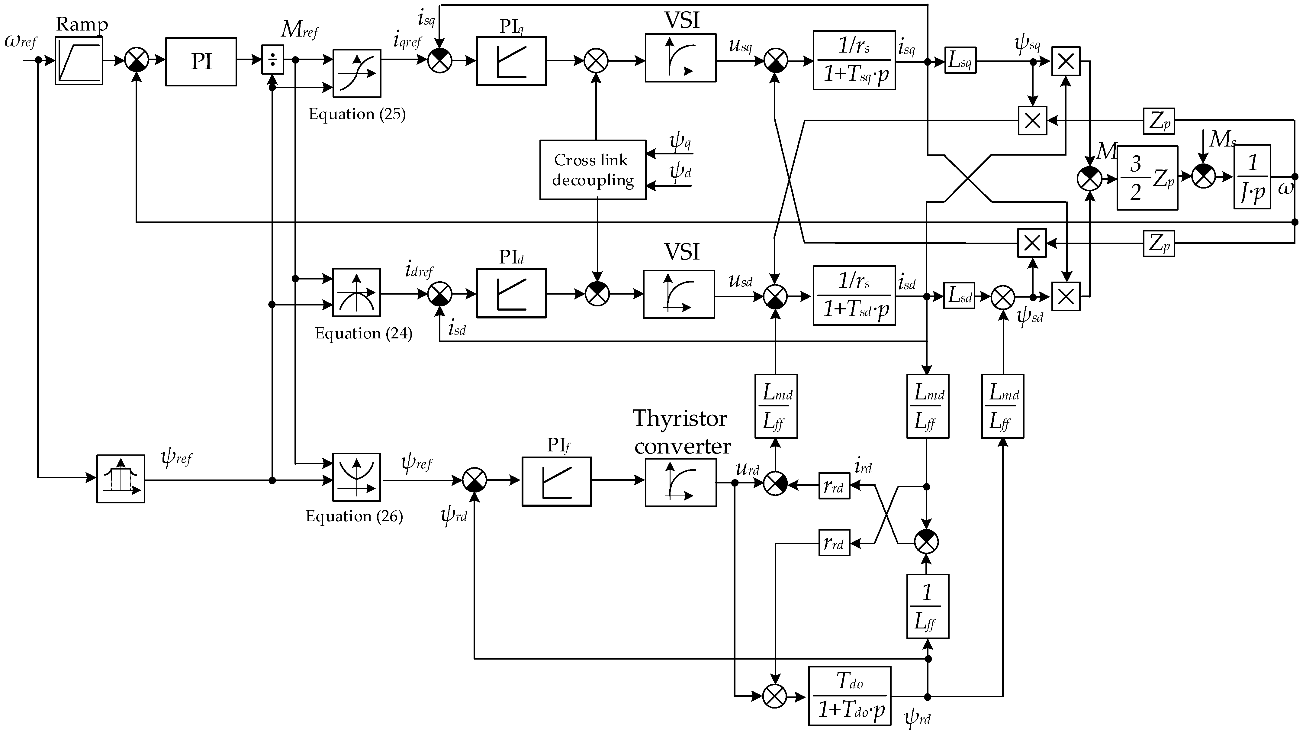
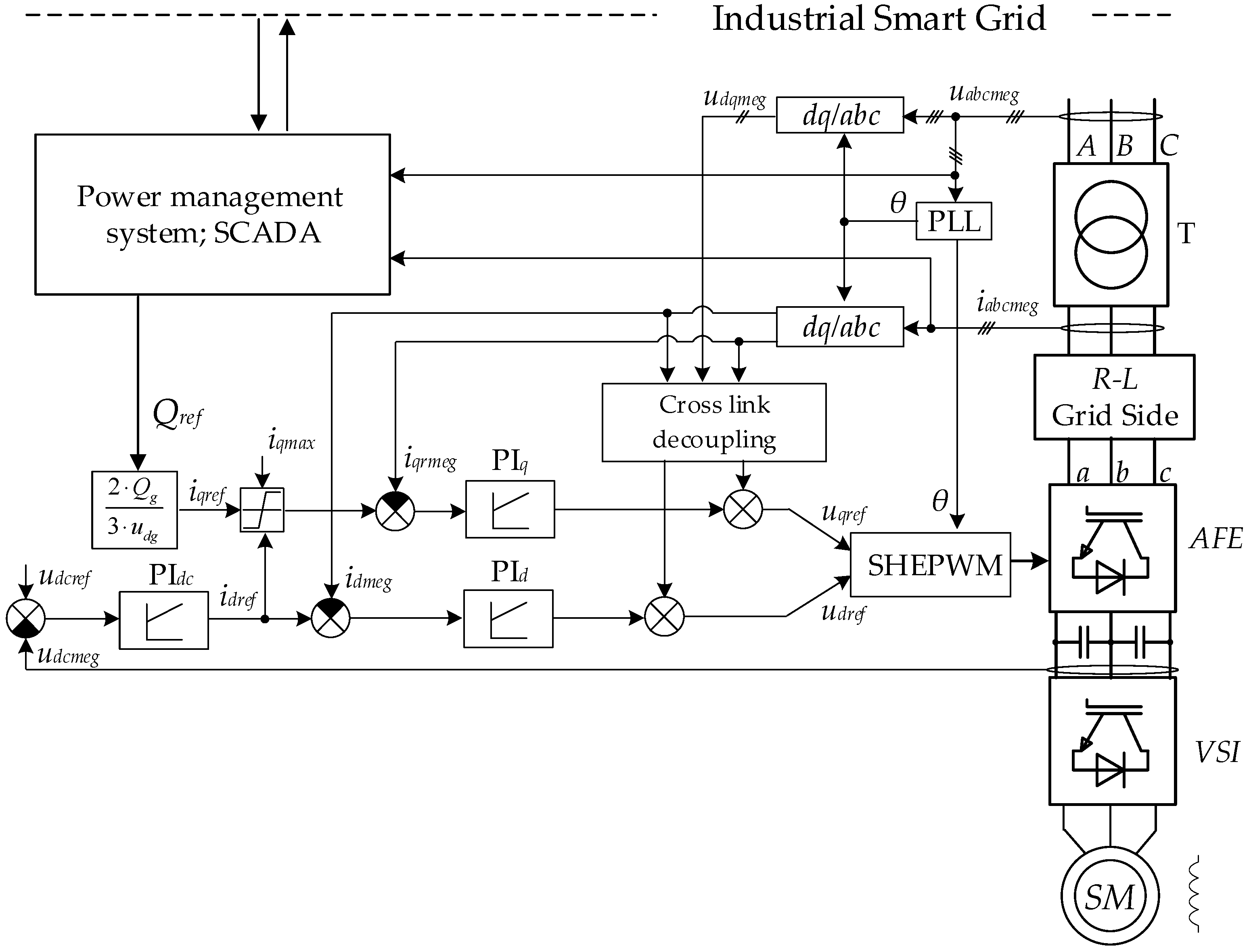
4. Synthesis of a 3L-NPC-AFE-VSI Control System

Figure 5 shows a 3L-NPC-AFE-VSI circuit diagram representing 24 fully controlled semiconductor modules T1–T24, 24 forward diodes D1–D24, 12 clamped diodes Dc1–Dc12; Sabc1AFESabc4AFE and Sabc1VSISabc4VSI are the states of the 3L-NPC-AFE-VSI semiconductor modules at each phase rack a, b and c, taking logical values 0 or 1; udc1, udc2 are the instantaneous voltage values on the equivalent capacities of the DC link; uabcAFE, uabcVSI and iabcAFE, iabcVSI are the phase voltages and currents of the 3L-NPC-AFE-VSI; Cdc1, Cdc2 are the equivalent DC link capacitance values.
When building a mathematical model, discrete logical functions fabc describing the states of modules in each 3L-NPC-AFE-VSI phase rack should be considered:
f a b c A F E = { 1 ,       ( S a b c 1 A F E   a n d   S a b c 2 A F E ) = 1   a n d     ( S a b c 3 A F E   a n d   S a b c 4 A F E ) = 0 0 ,       ( S a b c 2 A F E   a n d   S a b c 3 A F E ) = 1   a n d     ( S a b c 1 A F E   o r   S a b c 4 A F E ) = 0 1 ,     ( S a b c 3 A F E   a n d   S a b c 4 A F E ) = 1   a n d     ( S a b c 1 A F E   a n d   S a b c 2 A F E ) = 0 ,
f a b c V S I = { 1 ,       ( S a b c 1 V S I   a n d   S a b c 2 V S I ) = 1   a n d     ( S a b c 3 V S I   a n d   S a b c 4 V S I ) = 0 0 ,       ( S a b c 2 V S I   a n d   S a b c 3 V S I ) = 1   a n d     ( S a b c 1 V S I   o r   S a b c 4 V S I ) = 0 1 ,     ( S a b c 3 V S I   a n d   S a b c 4 V S I ) = 1   a n d     ( S a b c 1 V S I   a n d   S a b c 2 V S I ) = 0 .
Equations (35) and (36) are optimized to the state of the switching functions Fabc generating logic signals (0 or 1) that determine the voltage of the DC link connected to each 3L-NPC-AFE-VSI phase:
F a b c 1 A F E = f a b c A F E ( f a b c A F E + 1 ) 2 ;   F a b c 2 A F E = f a b c A F E ( f a b c A F E 1 ) 2 ;   F a b c 1 V S I = f a b c V S I ( f a b c V S I + 1 ) 2 ;   F a b c 2 V S I = f a b c V S I ( f a b c V S I 1 ) 2 ,
A system of equations describing electromagnetic processes was built based on Equations (35)–(37) and the voltage and current equilibrium equations obtained with Kirchhoff’s laws, as well as the power balance in a three-phase system, as follows:
{ u a b c A F E = u d c 1 D a b c 1 A F E + u d c 2 D a b c 2 A F E + i a b c A F E R a b c A F E + L a b c A F E d i a b c A F E d t u a b c V S I = u d c 1 D a b c 1 V S I + u d c 2 D a b c 2 V S I u d c 1 = ( F a 1 A F E i a A F E + F b 1 A F E i b A F E + F c 1 A F E i c A F E ) ( F a 1 V S I i a V S I + F b 1 i b V S I + F c 1 i c V S I ) C d c 1 p u d c 2 = ( F a 2 i a A F E + F b 2 i b A F E + F c 2 i c A F E ) ( F a 2 V S I i a V S I + F b 2 V S I i b V S I + F c 2 V S I i c V S I ) C d c 2 p D a b c 1 A F E = F a b c 1 A F E 1 3 n = a b . c F n 1 A F E ;   D a b c 2 A F E = F a b c 2 A F E 1 3 n = a b . c F n 2 A F E ; D a b c 1 V S I = F a b c 1 V S I 1 3 n = a b . c F n 1 V S I ;   D a b c 2 V S I = F a b c 2 V S I 1 3 n = a b . c F n 2 V S I . P g = u a g i a A F E + u b g i b A F E + u c g i c A F E Q g = 1 3 ( ( u b g u c g ) i a A F E + ( u c g u a g ) i b A F E + ( u a g u b g ) i c A F E )
where uabcg, uabcAFE and uabcVSI are the phase voltages; iabcAFE and iabcVSI are the phase currents; Fabc12AFE and Fabc12VSI are the switching functions in the dq0 reference frame; p is the instantaneous active power; q is the instantaneous reactive power.
The system of Equation (38) considers the discrete nature of generating the 3L-NPC-AFE-VSI output voltages and the voltage imbalance in the DC link. Figure 6 shows the block diagram of the developed logical–mathematical model.
The AFE control system is further synthesized in a rotating reference frame dq0 directed along the grid vector. After the abc/dq0 coordinate transformation, the system of Equations (38) takes the following form:
{ u d g = u d A F E + i d A F E R d A F E + L d A F E d i d A F E d t ω g L d A F E i q A F E 0 = u q A F E + i q A F E R q A F E + L q A F E d i q A F E d t + ω g L q A F E i d A F E u d q A F E = u d c 1 F d q 1 A F E + u d c 2 F d q 2 A F E u d q V S I = u d c 1 F d q 1 V S I + u d c 2 F d q 2 V S I u d c 1 = 3 2 ( F d 1 A F E i d A F E + F q 1 A F E i q A F E ) ( F d 1 V S I i d V S I + F q 1 V S I i q V S I ) C d c 1 p u d c 2 = 3 2 ( F d 2 A F E i d A F E + F q 2 A F E i q A F E ) ( F d 2 V S I i d V S I + F q 2 V S I i q V S I ) C d c 2 p P g = 3 2 u d g i d A F E Q g = 3 2 u d g i q A F E S g = 3 2 u d g i d A F E 2 + i q A F E 2
where udqg, udqAFE and udqVSI are the grid phase voltages; idqAFE and idqVSI are the phase currents; RdqAFE, LdqAFE are the active inductive resistances on the AFE side; ωg is the angular grid voltage frequency; Fdq12AFE and Fdq12VSI are the switching functions.
Figure 7 shows the block diagram of the 3L-NPC-AFE-VSI’s logical–mathematical model in the dq0 reference frame.
The system of Equation (39) shows that the reactive power consumed is fully determined by the reactive current iqAFE. Emerging iqAFE will cause a sharp increase in the voltage drop across the inductive resistance and, therefore, the need to increase the output voltage EAFE by the voltage drop value XLiq. The values of the maximum generated reactive power and current can be determined from the system of Equations (39) under the condition id = 0 (STATCOM mode) as follows:
Q g max = 3 2 ( u d g m U d c 2 π u d g 2 X L ) i q A F E max = 2 Q g max 3 u d g .
The Equations system (39) shows that with an increase in the idAFE current, the maximum reactive power will decrease. This is because the maximum apparent power consumption of the semiconductor converter is limited by the maximum active power consumption of the SMD (SgmaxPgmax). The reactive power limit is defined as follows:
Q g S g max 2 P g 2 .
This limitation in the AFE control system is implemented using the dependent current limitation according to the following formula:
i q i d A F E max 2 i d A F E 2 .
Figure 8 shows an AFE control system for reactive power compensation comprising two control loops. The inner current circuit is implemented in the dq0 reference frame, oriented to the grid phase voltage (voltage-oriented control (VOC)) [28,29,30]. The idAFE current provides DC voltage control. The iqAFE current is used to control reactive power. The circuit includes the following items: input AFE phase current iabcmeg and voltage uabcmeg; grid angle θ; references idqref and measured idqmeg phase currents in the dq0 coordinates; references udqAFEref and measured instantaneous phase voltage udqmeg in the dq0 coordinates; reference udcref and measured udcmeg DC voltage; and selective harmonic elimination pulse width modulation (SHEPWM). The AFE control system calculates the modulation index m and the shift angle α as follows:
m = π u d A F E 2 + u q A F E 2 2 U d c ,
α = a r c t g ( u q A F E u d A F E ) .
Of great promise is AFE control with dependent current limitation to compensate reactive power in a network as part of an industrial smart grid. When implementing reactive power compensation modes, the precalculation or real-time monitoring of reactive power in the grid is required to produce a command for the generation or consumption of reactive power Qref at the local AFE control level.

5. Experimental Studies

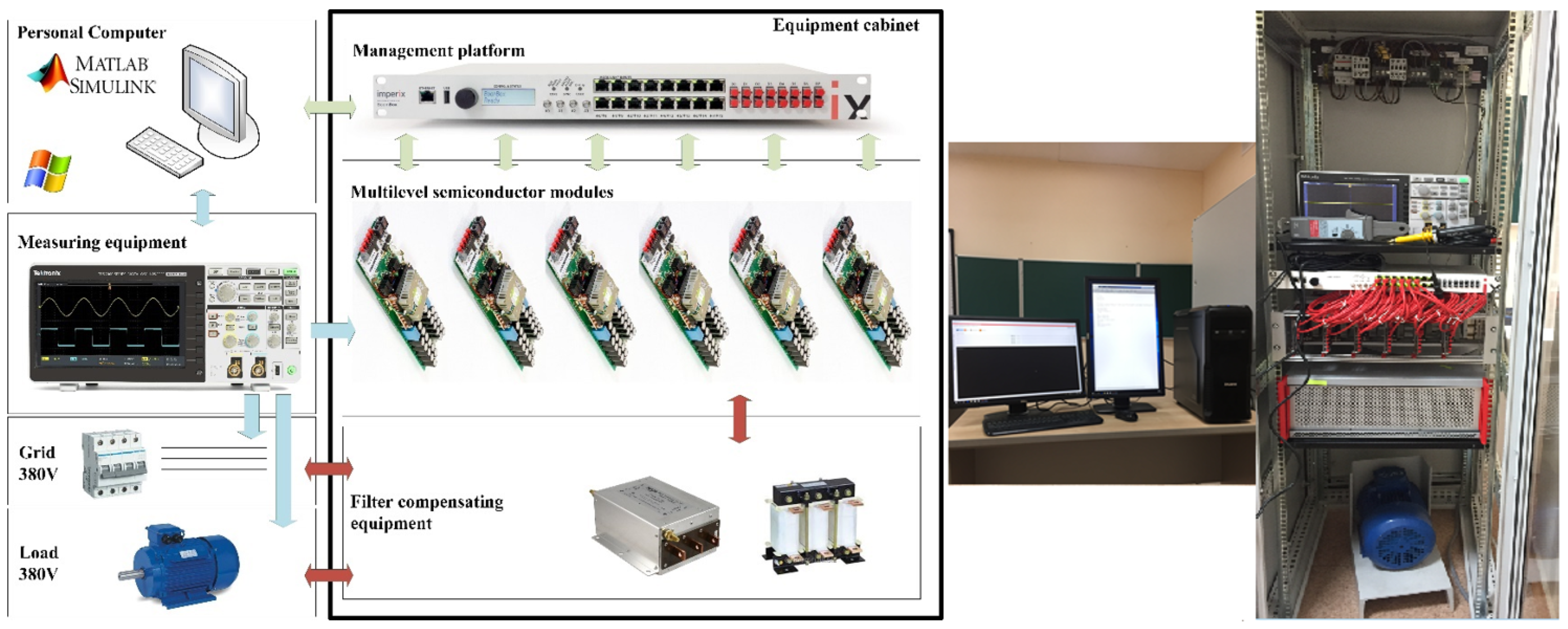
5.1. Laboratory Studies

Validation of mathematical models was carried out at a power conversion equipment laboratory. A photo and the equipment composition are presented in Figure 9. The specifications of the laboratory prototype and the testing system are presented in Table 1.
Direct access to the control signal of the semiconductor modules was gained through optic fiber inputs. Then, the galvanically isolated voltage probes of the DC and AC links at the converter input were connected to analog outputs. Overvoltage, overcurrent and overheating protection were built into each converter’s NPC cells, and the converters were programmed by the researchers using a built-in microcontroller and a complex programmable logic device (CPLD). The mezzanine module was designed to transmit signals from the optic inputs and the analog outputs between the CPLD and the BoomBox control platform, including a digital signal processor (DSP) and a field-programmable gate array (FPGA). The converter control tasks were distributed between the DSP and the FPGA. The FPGA controlled the correct distribution of the IGBT control impulses, and the DSP processed the converter control system program. The computing core of the DSP was a 32-bit TMS320C28346 processor manufactured by Texas Instruments with a clock rate of 300 MHz and featuring 256 MB NOR flash memory, 2 MB RAM and 300 MIPS (with a floating point).
To take an oscillogram, WindowsTM-based graphic software of the BoomBox control platform was used. The probes were connected to the BoomBox control platform using the plug-and-play method and received directly from the control platform. The output signal was transmitted over a screened twisted pair of probes integrated into RJ45 cables. The program code for the control platform was developed in the MATLAB/Simulink. A fragment of the developed model is shown in Figure 10.
The results of experimental studies of the AFE reactive power generation using the laboratory equipment are presented below. Figure 11 shows an experiment with three reference reactive power generations of 9 kVAr when active power consumption on the load side was from 0 to 8 kW. The AFE control system provided the set with the maximum apparent power of 10 kVA. The measured DC link voltage was constant, 600 V. As noted earlier, if power consumption from the load side increases, the AFE control system reduces the reactive current reference and, as a result, the generated reactive power.
The next experiment with the active power regenerative mode from 0 to 8 kW is shown in Figure 12. As in the previous experiment, the level of generated reactive power decreased with an increase in the regenerative active power, and the apparent power in the system was controlled by the AFE at the reference value of 10 kVA.
The modulation index in both experiments varied from 1.1 at the maximum reactive power generation of 10 kVAR to 1.0 at the minimum 2 kVAR. Thus, the results of the studies performed using the laboratory equipment confirmed the adequacy of the obtained constraints (41) and (42) when using an AFE as a reactive power compensator.

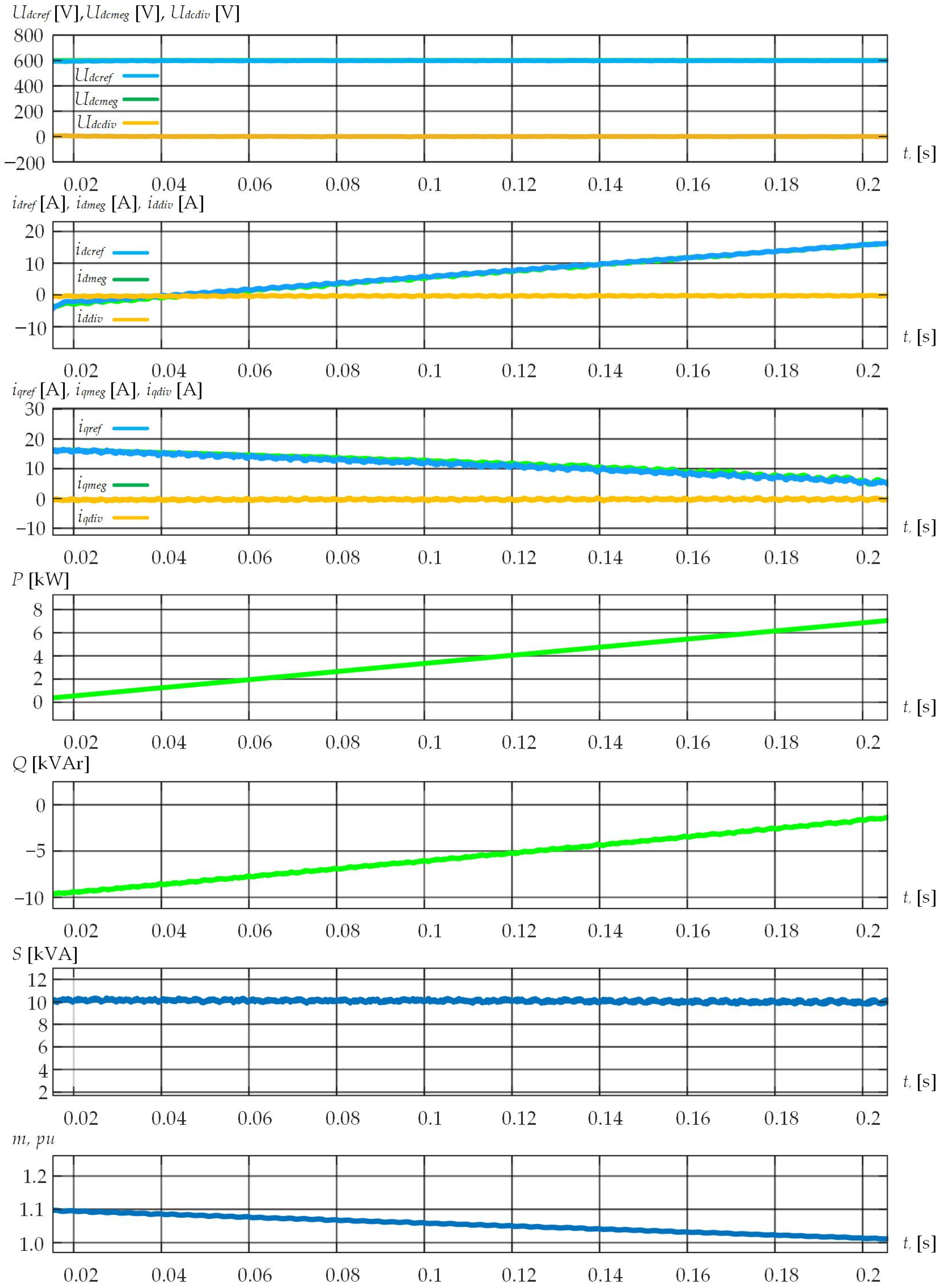
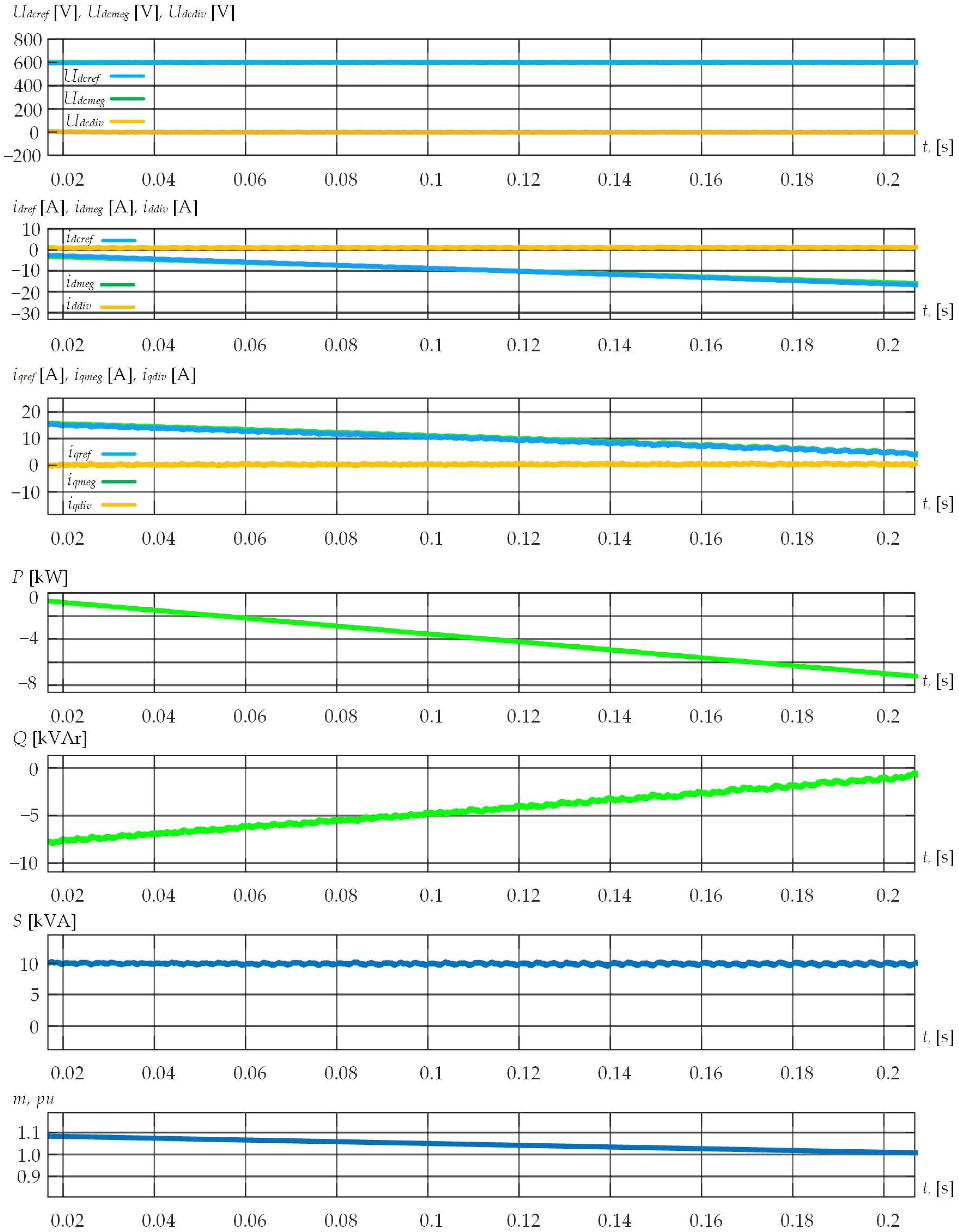
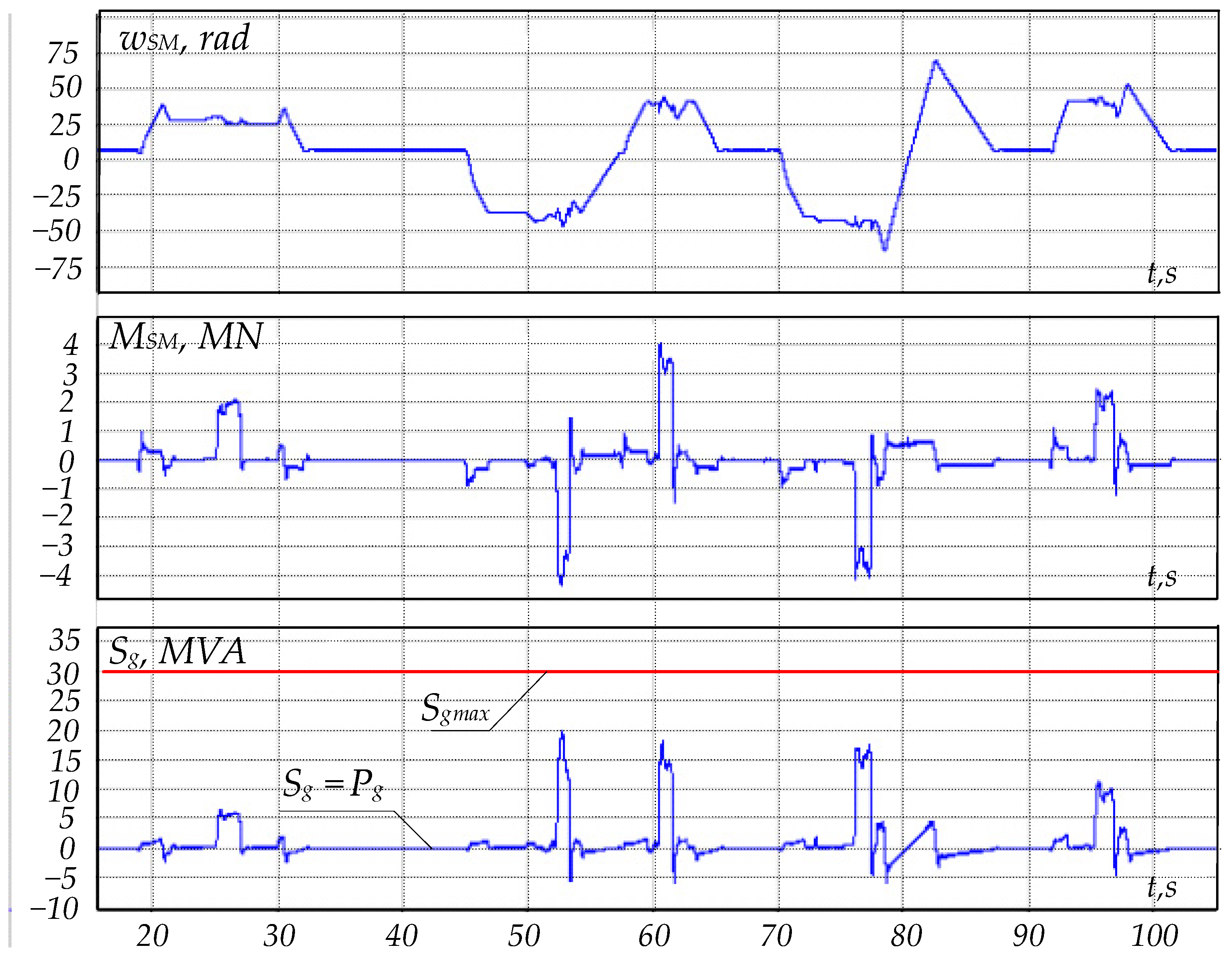
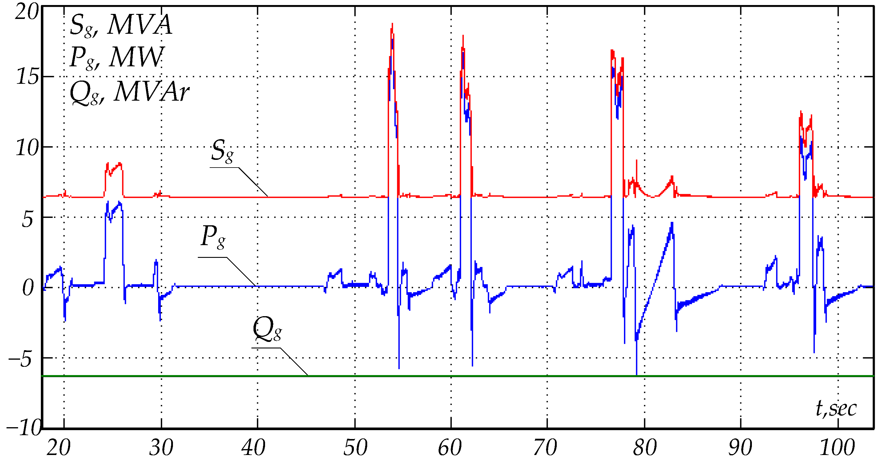
5.2. Industrial Experiment

The main drive of a plate mill rolling stand was investigated as the experimental object to verify the adequacy of the developed logical–mathematical models and the proposed reactive power compensation technique. An industrial drive is a system in which a DYMMZ 8025-8V synchronous motor with a rated power of 12 MW of each working roll is connected to three parallel-connected converters based on an AFE (PWM with the SHE algorithm) and a VSI (SVPWM algorithm). The object’s electrical circuit is shown in Figure 13 while the basic specifications of the motor are provided in Table 2, and those of the converter in Table 3.
Based on the initial object parameters, the maximum reactive power of 80 kVAR was found using Equation (40) with a modulation index of 1. When increasing the modulation index to 1.1, the maximum reactive power would increase sharply to 2.5 MVAR. Generating reactive power above these values without increasing the DC link voltage becomes problematic. An increased modulation index may cause unstable operation of the AFE due to voltage drops in the DC link when an abruptly variable load emerges on the SMD side. Increasing the DC link voltage also deteriorates the operating conditions of the SMD and semiconductor modules. Thus, to generate reactive power, the SMD’s idle mode and roughing-down conditions were used. Figure 14 shows the SMD operation load diagram for mastering the reactive power generation mode. The modulation index was set to 1.1 where the total generated reactive power was 6 MVAR. Figure 15 shows the active, reactive and apparent power measurement results.

6. Conclusions

This paper reviews the possibilities of reactive power compensation and power quality improvement in the grid using a high-power 3L-NPC-AFE-VSI-SMD. The analysis of the obtained results led to the following conclusions:
  • The review of previous studies revealed underestimated limitations when implementing reactive power compensation modes using a powerful regenerative controlled-speed synchronous motor drive based on a 3L-NPC-AFE-VSI;
  • Industrial 3L-NPC-AFE-VSI-SMD systems are developed without considering the possibility of reactive power compensation in the grid. Active power control is a priority; furthermore, it significantly limits the reactive power generation range;
  • Increasing the DC link voltage and/or the 3L-NPC-AFE modulation index allows for the increasing and controlling of the compensated reactive power. This paper proposes formulas for determining the maximum reactive power and current;
  • Experimental studies at a rolling mill showed that with the recommended modulation index and DC link voltage values, it was virtually impossible to generate reactive power. It was proposed to increase the modulation index to 1.1 during low-load SDM operation modes and at idle, which allowed generating reactive power at a level of 15% of the rated active power;
  • The proposed 3L-NPC-AFE reactive power control technique with a dependent current limitation can be used as part of an industrial smart grid to reduce the reactive power at the boundary.

Author Contributions

Conceptualization, A.S.M.; methodology, A.S.M.; software, T.A.L.; validation, A.A.N.; formal analysis, A.S.M. and A.A.N.; investigation, A.S.M. and T.A.L.; data curation, A.S.M. and T.A.L.; writing—review and editing, A.S.M.; visualization, A.S.M. All authors have read and agreed to the published version of the manuscript.

Funding

This work was financially supported by Moscow Polytechnic University under a grant named after Pyotr Kapitsa.

Institutional Review Board Statement

Not applicable.

Informed Consent Statement

Not applicable.

Data Availability Statement

Not applicable.

Conflicts of Interest

The authors declare no conflict of interest.

References

  1. Abu-Rub, H.; Bayhan, S.; Moinoddin, S.; Malinowski, M.; Guzinski, J. Medium-Voltage Drives: Challenges and existing technology. IEEE Power Electron. Mag. 2016, 3, 29–41. [Google Scholar] [CrossRef]
  2. Rajesh, D.; Ravikumar, D.; Bharadwaj, S.K.; Vastav, B.K.S. Design and control of digital DC drives in steel rolling mills. In Proceedings of the International Conference on Inventive Computation Technologies (ICICT), Coimbatore, India, 26–27 August 2016. [Google Scholar] [CrossRef]
  3. Jing, T.; Maklakov, A.S. A Review of Voltage Source Converters for Energy Applications. In Proceedings of the International Ural Conference on Green Energy, Chelyabinsk, Russia, 4–6 October 2018. [Google Scholar] [CrossRef]
  4. Steczek, M.; Jefimowski, W.; Szeląg, A. Application of Grasshopper Optimization Algorithm for Selective Harmonics Elimination in Low-Frequency Voltage Source Inverter. Energies 2020, 13, 6426. [Google Scholar] [CrossRef]
  5. Al-Hitmi, M.; Ahmad, S.; Iqbal, A.; Padmanaban, S.; Ashraf, I. Selective Harmonic Elimination in a Wide Modulation Range Using Modified Newton–Raphson and Pattern Generation Methods for a Multilevel Inverter. Energies 2018, 11, 458. [Google Scholar] [CrossRef]
  6. Orcajo, G.A.; Diez, J.R.; Cano, J.M.; Norniella, J.G.; Pedrayes González, J.F.; Rojas, C.H. Coordinated Management of Electrical Energy in a Steelworks and a Wind Farm. IEEE Trans. Ind. Appl. 2022, 58, 5488–5502. [Google Scholar] [CrossRef]
  7. Alonso Orcajo, G.; Rodríguez, D.J.; Cano, J.M.; Norniella, J.G.; Ardura, G.P.; Llera, T.R.; Cifrián, R.D. Retrofit of a Hot Rolling Mill Plant with Three-Level Active Front End Drives. IEEE Trans. Ind. Appl. 2018, 54, 2964–2974. [Google Scholar] [CrossRef]
  8. Orcajo, G.A.; Rodríguez, J.; Ardura, P.; Cano, J.M.; Norniella, J.G.; Llera, R.; Cifrián, D. Dynamic Estimation of Electrical Demand in Hot Rolling Mills. IEEE Trans. Ind. Appl. 2016, 52, 2714–2723. [Google Scholar] [CrossRef]
  9. Pandit, P.; Mazumdar, J.; May, T.; Koellner, W.G. Real-Time Power Quality Measurements from a Conventional AC Dragline. IEEE Trans. Ind. Appl. 2010, 46, 1755–1763. [Google Scholar] [CrossRef]
  10. Dybko, M.A.; Brovanov, S.V.; Kharitonov, S.A. Mathematical Simulation Technique for Power Systems based on Diode-Clamped Multilevel VSC. In Proceedings of the Eurocon 2013, Zagreb, Croatia, 1–4 July 2013; pp. 941–948. [Google Scholar] [CrossRef]
  11. Slezhanovskii, O.V.; Datskovsky, L.K.; Kuznetsov, I.S.; Lebedev, E.D.; Tarasenko, L.M. Systems of Subordinate Regulation of AC Electric Drives with Valve Converters; Energoatomizdat: Moscow, Russia, 1983. [Google Scholar]
  12. Cheng, J.; Xu, T.; Chen, D.; Chen, G. Dynamic and steady state response analysis of selective harmonic elimination in high power inverters. IEEE Access 2021, 9, 75588–75598. [Google Scholar] [CrossRef]
  13. Steczek, M.; Chudzik, P.; Szeląg, A. Combination of SHE- and SHM-PWM techniques for VSI DC-link current harmonics control in railway applications. IEEE Trans. Ind. Electron. 2017, 64, 7666–7678. [Google Scholar] [CrossRef]
  14. Khattak, F.A.; Rehman, H.U. Improved Selective Harmonics Elimination Strategy for Multilevel Inverters with Optimal DC Values. In Proceedings of the International Conference on Emerging Power Technologies, Topi, Pakistan, 1–6 April 2021. [Google Scholar] [CrossRef]
  15. Patil, S.D.; Kadu, A.; Dhabe, P. Improved Control Strategy for Harmonic Mitigation in Multilevel Inverter. In Proceedings of the 5th International Conference on Intelligent Computing and Control Systems, Madurai, India, 6–8 May 2021. [Google Scholar] [CrossRef]
  16. Moeini, A.; Dabbaghjamanesh, M.; Kimball, J.W.; Zhang, J. Artificial neural networks for asymmetric selective harmonic current mitigation-PWM in active power filters to meet power quality standards. IEEE Trans. Ind. Appl. 2020. [Google Scholar] [CrossRef]
  17. de Carvalho Alves, M.D.; Leão e Silva Aquino, R.N.A. Digital implementation of SHE-PWM modulation on FPGA for a multilevel inverter. In Proceedings of the Simposio Brasileiro de Sistemas Eletricos (SBSE), Niteroi, Brazil, 1–6 May 2018. [Google Scholar] [CrossRef]
  18. Chen, J.; Shen, Y.; Chen, J.; Bai, H.; Gong, C.; Wang, F. Evaluation on the Autoconfigured Multipulse AC/DC Rectifiers and Their Application in More Electric Aircrafts. IEEE Trans. Transp. Electrif. 2020, 6, 1721–1739. [Google Scholar] [CrossRef]
  19. Padmanaban, S.; Dhanamjayulu, C.; Khan, B. Artificial neural network and Newton Raphson (ANN-NR) algorithm based selective harmonic elimination in cascaded multilevel inverter for PV applications. IEEE Access 2021, 9, 75058–75070. [Google Scholar] [CrossRef]
  20. Radionov, A.A.; Gasiyarov, V.R.; Maklakov, A.S. Hybrid PWM on the basis of SVPWM and SHEPWM for VSI as part of 3L-BtB-NPC converter. In Proceedings of the IECON 43rd Annual Conference of the IEEE Industrial Electronics Society, Beijing, China, 29 October–1 November 2017; pp. 1232–1236. [Google Scholar] [CrossRef]
  21. Nikolaev, A.A.; Gilemov, I.G.; Denisevich, A.S. Analysis of Influence of Frequency Converters with Active Rectifiers on the Power Quality in Internal Power Supply Systems of Industrial Enterprises. In Proceedings of the International Conference on Industrial Engineering, Applications and Manufacturing, Moscow, Russia, 1–4 May 2018. [Google Scholar]
  22. Wu, B.; Narimani, M. High-Power Converters and AC Drives, 2nd ed.; Wiley-IEEE Press: Hoboken, NJ, USA, 2017. [Google Scholar]
  23. Nikolaev, A.; Maklakov, A.; Bulanov, M.; Gilemov, I.; Denisevich, A.; Afanasev, M. Current Electromagnetic Compatibility Problems of High-Power Industrial Electric Drives with Active Front-End Rectifiers Connected to a 6–35 kV Power Grid: A Comprehensive Overview. Energies 2023, 16, 293. [Google Scholar] [CrossRef]
  24. Holmes, D.G.; Lipo, T.A. Pulse Width Modulation for Power Converters: Principles and Practice, 1st ed.; Wiley-IEEE Press: Hoboken, NJ, USA, 2003. [Google Scholar]
  25. Maklakov, A.S.; Jing, T.; Radionov, A.A.; Gasiyarov, V.R.; Lisovskaya, T.A. Finding the best programmable PWM pattern for three-level active front-ends at 18-pulse connection. Machines 2021, 9, 127. [Google Scholar] [CrossRef]
  26. Nikolaev, A.A.; Gilemov, I.G.; Bulanov, M.V.; Kosmatov, V.I. Providing Electromagnetic Compatibility of High-Power Frequency Converters with Active Rectifiers at Internal Power Supply System of Cherepovets Steel Mill. In Proceedings of the International Scientific-Technical Conference Alternating Current Electric Drives, Ekaterinburg, Russia, 1–8 May 2021. [Google Scholar]
  27. Marquez Alcaide, A.; Leon, J.I.; Laguna, M.; Gonzalez-Rodriguez, F.; Portillo, R.; Zafra-Ratia, E.; Vazquez, S.; Franquelo, L.G.; Bayhan, S.; Abu-Rub, H. Real-Time Selective Harmonic Mitigation Technique for Power Converters Based on the Exchange Market Algorithm. Energies 2020, 13, 1659. [Google Scholar] [CrossRef]
  28. Martínez, C.; Rohten, J.; Garbarino, M.; Andreu, M.; Silva, J.; Baier, C.; Morales, R. Operating Region for AFE Configuration under Variable Frequency Grid. In Proceedings of the IEEE International Conference on Automation/XXIV Congress of the Chilean Association of Automatic Control (ICA-ACCA), Valparaíso, Chile, 22–26 March 2021; pp. 1–6. [Google Scholar] [CrossRef]
  29. Espinosa, E.E.; Melin, P.E.; Garcés, H.O.; Baier, C.R.; Espinoza, J.R. Multicell AFE Rectifier Managed by Finite Control Set–Model Predictive Control. IEEE Access 2021, 9, 137782–137792. [Google Scholar] [CrossRef]
  30. Chowdhury, M.M.R.; Sütő, Z. Validation of a real-time simulation model of a three-phase Active-Front-End (AFE) rectifier. In Proceedings of the 8th International Youth Conference on Energy (IYCE), Eger, Hungary, 6–9 July 2022; pp. 1–5. [Google Scholar] [CrossRef]
Figure 1. SMD system diagram.
Designs 07 00062 g001
Figure 2. Three-phase SM diagram.
Designs 07 00062 g002
Figure 3. Block diagram of the VSI-SMD vector control system.
Designs 07 00062 g003
Figure 4. The specifics of AFE operation during reactive power compensation. (a) Single-phase equivalent circuit of an AFE. (b) Reactive power generation mode without active power consumption. (c) Reactive power generation mode with active power consumption. (d) Reactive power generation mode with active power generation.
Designs 07 00062 g004
Figure 5. Block diagram of a 3L-NPC-AFE-VSI.
Designs 07 00062 g005
Figure 6. AFE voltage-oriented control block diagram in the abc reference frame.
Designs 07 00062 g006
Figure 7. AFE voltage-oriented control block diagram in the dq0 rotating reference frame.
Designs 07 00062 g007
Figure 8. AFE voltage-oriented control block diagram.
Designs 07 00062 g008
Figure 9. The laboratory equipment.
Designs 07 00062 g009
Figure 10. Part of the mathematical model of the object (label * is default data port).
Designs 07 00062 g010
Figure 11. AFE reactive power generation mode with active power consumption.
Designs 07 00062 g011
Figure 12. AFE reactive power generation mode with active power regeneration.
Designs 07 00062 g012
Figure 13. Powerful regenerative controlled-speed synchronous motor drive power diagram.
Designs 07 00062 g013
Figure 14. SMD operation load diagram during the roughing-down.
Designs 07 00062 g014
Figure 15. Reactive power generation by a 3L-NPC-AFE at 15% of the rated SMD power during the roughing-down.
Designs 07 00062 g015
Table 1. Equipment parameters.
Power modules1 × P924F33 Vincotech; reverse voltage IGBT, 600 V; permissible continuous current IGBT, 30 A; admissible continuous current of the reverse diode, 27 A; maximum switching frequency IGBT, 50 kHz; voltage drop, 1.5–2 V
Capacitors2 × 517 μF Panasonic EEU-EE2W470S (two batteries of 11 × 47 μF each); maximum voltage, 450 V
Control drivers4 × Avago ACPL-P345
Current sensor1 × LEM HLSR 20-P/SP33; nominal range, ±20 A, 450 kHz; instrument error, ±1%
Voltage sensor1 × resistive voltage divider + Avago ACPL-C87B; bandwidth, 25 kHz; instrument error, ±0.1%
FPGA1 × Xilinx XC9536XL-10VQG44C, 10 ns; 36 microelements
Microcontrollers2 × Microchip PIC24F04KA201, 16 bit, 16 MHz; 9 × 10-bit ADCs; sampling rate, 500 ksps
Table 2. Initial motor specifications.
ParameterDesignationValue
Rated powerP2, MW12
Rated stator currentIs, A3600
Rated stator voltageUs, kV3.3
Rated frequencyfs, Hz10
Stator’s active resistanceRs, Ohm0.167
Rotor’s active resistanceRr, Ohm0.066
Inductive reactance in the D-axisXd, Ohm0.12
Inductive reactance in the Q-axisXq, Ohm0.113
Overload capacity 3
Table 3. Initial converter specifications.
ParameterDesignationValue
Maximum active powerPAFE, MW12
Rated currentIAFE, A2400
Rated voltageUAFE, kV3.3
Rated frequencyfg, Hz50
DC voltageUdc, V5020
Modulation indexp.u.0.85
AFE input inductancemH7.5
DC link capacityµF6170
Overload capacity 1.2
Disclaimer/Publisher’s Note: The statements, opinions and data contained in all publications are solely those of the individual author(s) and contributor(s) and not of MDPI and/or the editor(s). MDPI and/or the editor(s) disclaim responsibility for any injury to people or property resulting from any ideas, methods, instructions or products referred to in the content.

