


Modeling and Control of a Multiple-Heat-Exchanger Thermal Management System for Conventional and Hybrid Electric Vehicles
Department of Mechanical Engineering, Clemson University, Clemson, SC 29631, USA
*
Author to whom correspondence should be addressed.
Designs 2023, 7(1), 19; https://doi.org/10.3390/designs7010019
Submission received: 12 December 2022
/
Revised: 12 January 2023
/
Accepted: 27 January 2023
/
Published: 1 February 2023
(This article belongs to the Special Issue Advanced Thermal Management Technologies: Experimental Case Studies, Numerical Modelling, and Topology Optimization)
Abstract
:The powertrain in combustion engine and electric vehicles requires a thermal management system to regulate the operating temperature of the under-hood components. The introduction of computer-controlled cooling system actuators (e.g., variable speed fans, pump, and valves) enables power savings over drive cycles. The radiator is typically sized for maximum heat rejection per environmental and vehicle thermal loading conditions. This paper explores the use of multiple radiators to adapt the cooling system operations to driving demands. A nonlinear multiple-input (i.e., fan array speed, pump, and outlet valve positions) thermal model is presented to predict system behavior. A stateflow controller has been designed and implemented to maintain the component temperature within a desired range (~80 °C). A series of experimental tests have been conducted to compare the proposed architecture’s performance against a single radiator design. A standard driving cycle featuring low (20 kW) and high (40 kW) heat loads was implemented in the laboratory for a vehicle starting from rest. The coolant temperature tracking, fan speeds, and fan power draw were studied over the representative operating cycle. The test results show a much faster warmup time (~10 min) and temperature tracking for the twin radiator experimental test as compared to the single radiator (~13 min). The net fan energy consumption was reduced by 4.6% with the twin radiator as opposed to the single-radiator configuration. Considering that engines usually operate at idle to medium loads, these findings can improve the powertrain’s overall performance.
1. Introduction
The ground transportation industry requires versatile vehicle designs that can operate in varying environments to meet customer demands and satisfy legislative requirements. Manufacturers must consider the powertrain designs (internal combustion engine, electric motors with a battery pack) and associated thermal management system (TMS) for driving cycles during the design phase. This leads to the oversizing of system components for the max possible heat loads, which in turn increases the TMS power consumption. Power is supplied to electromechanical actuators so that component temperatures are maintained within the prescribed limits. The TMS architectures have computer-controlled variable speed fans, pumps, and flow control valves [1]. This approach enables the minimization of cooling system power consumption while maintaining the desired temperature. Studies by Saidur et al. [2] and De Almeida et al. [3] demonstrated the potential energy and cost savings of variable speed drives for electrical motors and pumps. Electrical vehicles (EV) have a higher energy efficiency but require a lower operating temperature in comparison to internal combustion (IC) engine-propelled vehicles [4]. An inverse correlation between a battery’s capacity fade rate (i.e., battery life) and temperature exists according to Smith et al. [5]. Similarly, an IC engine’s life is also reduced at higher temperatures due to the increase in the wear and tear of parts [6]. Regardless of the power source, an effective cooling system is crucial for the overall efficiency of a vehicle.
Controlling the operating temperatures of the various components at their peak efficiency values is one of the many difficulties faced by cooling system design engineers. These temperatures are controlled within a specified range using a variety of cooling architectures (e.g., single-radiator, multi-core radiators, and heat pipe-based cooling systems) and modes (e.g., air, liquid, and hybrid). The range is determined based on the component to be cooled. For instance, IC engines have a much greater tolerance for temperature variations when compared to electric motors. This was demonstrated by Lang et al. [7] and Park and Jung [8,9] in their respective computer simulations of a hybrid electric vehicle (HEV) cooling system. Additionally, the various driving modes of an HEV—pure electric, pure combustion, and hybrid—each have their own cooling requirements. A cooling system built to handle a single thermal load may be insufficient in handling rapidly changing operating circumstances. Moreover, planning for the best operating and cooling conditions wastes energy and degrades performance. Consequently, it is necessary to modify the cooling system to meet real-time requirements.
Automotive cooling systems can be optimized by altering internal variables (e.g., radiator size, coolant pump design, and operating mode) and controlling system variables (e.g., fluid flow rates). A novel non-iterative computational calculation method for crossflow heat exchangers was developed by Węglarz et al. [10]. Their proposed model considers physical dimensions (e.g., Reynold’s and Nusselt numbers) and control variables (e.g., coolant volumetric flow rate) to estimate the heat removal rate. Delouei et al. [11,12] showed the effects of using ultrasonic vibration technology to improve the performance of a finned heat exchanger. They applied this effect to improve the overall efficiency of the thermal management system for cooling electronics. Donno et al. [13] created a design optimization method for automotive cooling system centrifugal pumps. Wang et al. successfully reduced the radiator power consumption by 67% by controlling the angular speeds of a fan array [14]. A review of the Euro4-EPA/02 standard was discussed by Valaszkai and Jouannet [15]. They proposed possible technical solutions to optimizing a heavy-duty truck’s cooling system in order to meet said standards. A geometrical design optimization tool for a water-cooling system of a high-power insulated gate bipolar transistor was developed by Bahman and Blaabjerg [16]. Su et al. [17] integrated a set of thermoelectric generators into an engine cooling system for energy optimization. Plessis et al. [18] conducted a pilot study to determine the cost effectiveness of variable speed drives for a mine cooling system.
System dynamic modeling, controller design, and experimental research have been conducted on a scalable multi-radiator TMS concept. By actively controlling fluid flows across individual heat exchangers, the desired operating temperature can be finetuned. Ideally, additional smaller radiators can be added based on the cooling demands. The following sections make up the rest of the article. In Section 2, the proposed system is further described. The modeling and controller design will be discussed in Section 3. Following that, a case study and the experimental findings are described in Section 4. The conclusion is presented in Section 5 and is followed by a Nomenclature List.
2. Single versus Multiple Heat Exchangers in a Cooling System Design
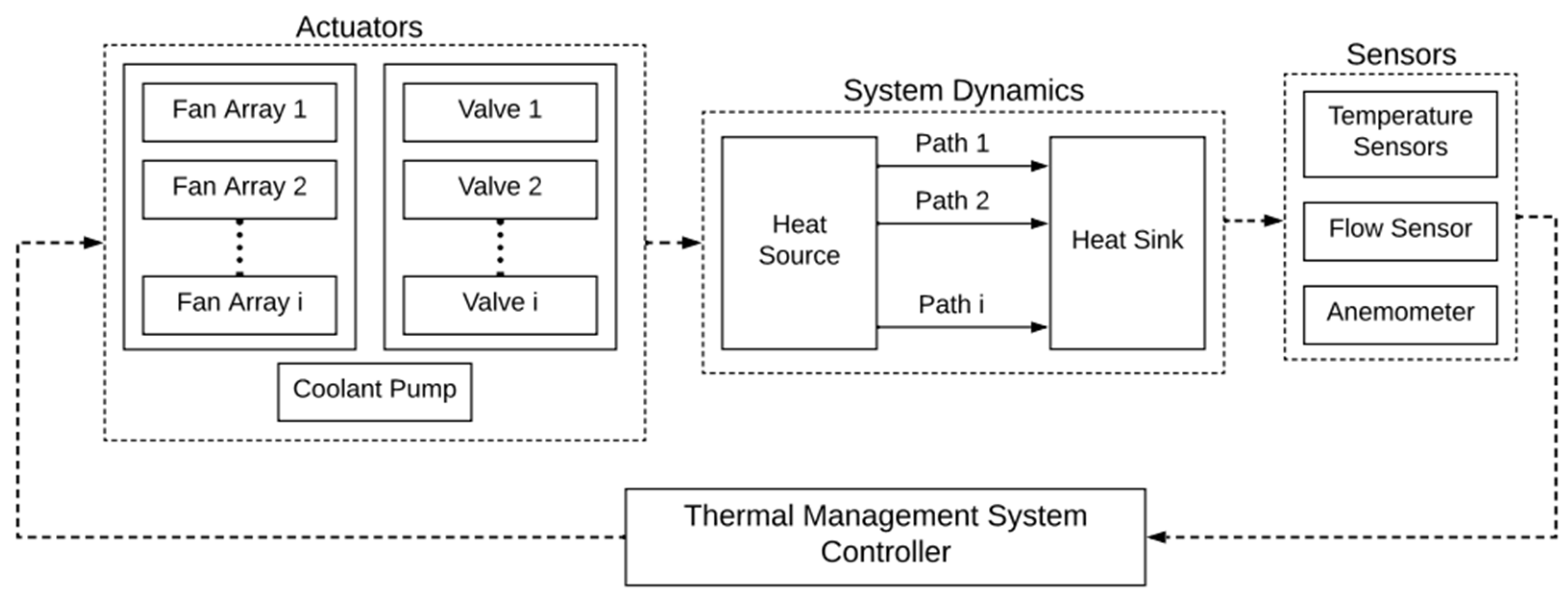
The traditional powertrain design typically uses a single radiator to meet a vehicle’s cooling needs. A disadvantage to this approach is the component oversizing required to meet the maximum thermal load. Often, vehicles rarely operate at extreme conditions, except for limited scenarios (e.g., going uphill during high-temperature conditions). The introduction of multiple radiators in parallel can alleviate this issue in terms of the under-hood space layout by using smaller components and lower flow rates during a reduced thermal load. Additionally, the proposed system can provide redundancies in cases of catastrophic failure and provide a limp-home mode. The added weight of the additional components is expected to be negligible compared to the overall vehicle mass but may be offset with gains in the system efficiency or performance. Figure 1 compares a traditional cooling system architecture to the proposed scalable multi-radiator TMS. Several additional components are introduced in the proposed architecture—n-controllable radiator outlet valves, swirl pots, variable speed coolant pumps, and radiator fans. The outlet valve’s function is to restrict the coolant flow across their respective radiators before mixing in the swirl pot. The swirl pot ensures a uniform temperature coolant supply to the heat source. The variable speed pump and fans allow the coolant and air flow rates to be dynamically controlled based on requirements. Several assumptions are implied for the system modeling process.
- A1.
- Thermal nodal network assumes a lumped capacitive model.
- A2.
- Material properties are isotropic.
- A3.
- Fluid flows are fully developed.
- A4.
- Heat addition/removal takes place only at the source/sink.
- A5.
- The outlet valves open or close linearly without turbulence.
- A6.
- The engine/radiator core temperatures are equal to the coolant temperature at the respective outlets.
3. Modeling and Control of the Thermal System
A set of mathematical models were developed to describe the scalable multi-radiator cooling system. The model encompasses governing equations, fan and pump power consumption routines, and heat flow pathways for a comprehensive system analysis. The system’s thermal nodal network primarily features convection heat transfer. The ith radiator’s coolant volumetric flow rate, , is a function of the outlet valve position, , and the total coolant flow rate, . The valves are either open () or closed ().
The heat input, , can correspond to chemical fuel combustion or joules heating processes for E/HE vehicles. The radiator’s heat rejection rate to the ambient, , was modeled using the NTU-Effectiveness method to keep it independent of the downstream fluid temperatures.
The overall volumetric flow rates for the coolant, , and air, , are regulated using computer-controlled variable speed actuators (i.e., pump and fans). The energy consumption of the radiator fans and coolant pump was experimentally investigated using current and frequency readings (i.e., , ) and plotted against the fan rotor and pump shaft angular speeds to obtain empirical relations. The fans are controlled by varying the current, , whereas the pump is controlled by varying the applied frequency, . The experimental readings for the voltage and current are presented in Table 1. Note that there are three radiator fans per radiator in the experimental setup.
A nonlinear state space model can effectively represent the experimental setup with internal cavity volumes (i.e., and ), nodal temperatures (i.e., and ), and flow rates (i.e., and ) as the system constants, states, and inputs, respectively.
where and are the air volumetric flow rate and effectiveness for the ith radiator, respectively.
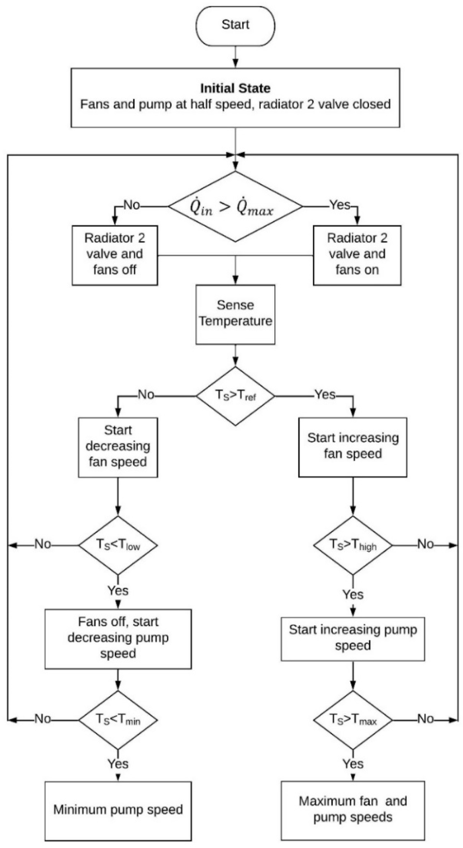
A stateflow controller was designed to regulate the coolant temperature within the desired range (i.e., ), as shown in Figure 2. The radiator fans and outlet valve for the second radiator are switched off for low thermal loads. The setup starts with fans and a pump at half-capacity. Even for , the coolant pump provides the minimum flow to allow for circulation within the circuit, but fans are turned off. As the device temperature crosses the minimum threshold temperature (i.e., , the pump speed is linearly increased until it reaches the half flowrate at . At this point, the fans are turned on, and their speed rises such that, at , both the pump and fans are at their half-speed values. The fan speed trend continues until the . The coolant flow rate starts increasing again at . Both the pump and fan speeds are maxed out beyond .
4. Experimental System and Test Results
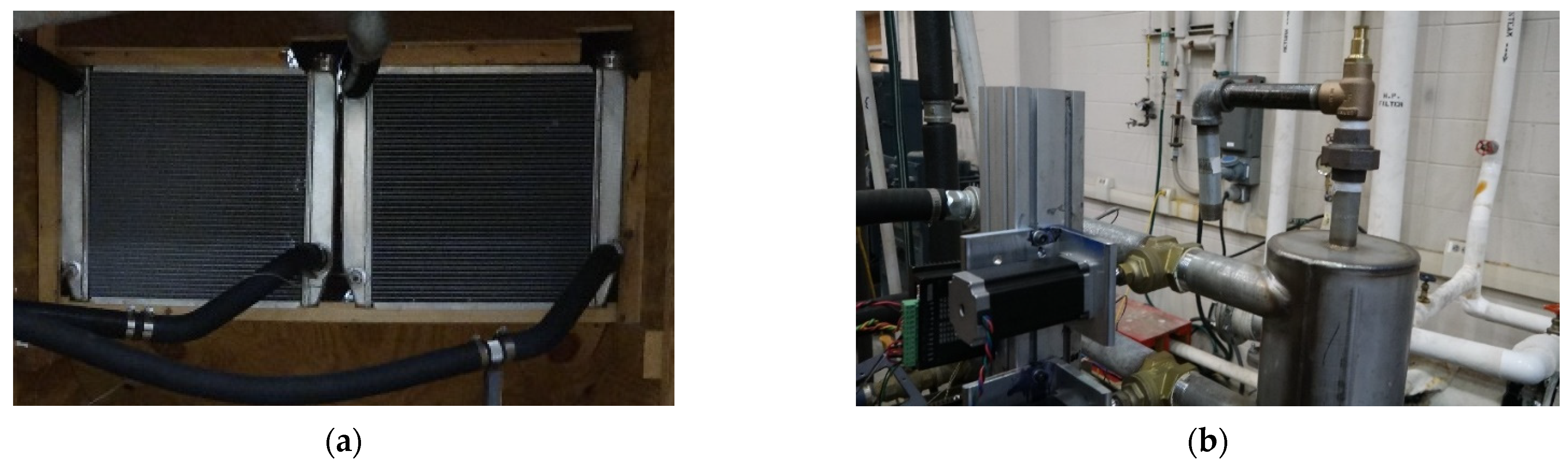
The performance of the multi-radiator concept was experimentally investigated in a laboratory. The experimental test bench shown in Figure 3 includes a set of identical radiators cooling a 5.0 L international V8 diesel engine block. The engine block acts as a thermal capacitor for the cooling circuit. The heat load is controlled using a facility steam-powered shell and a tube heat exchanger. The coolant flows from the twin radiators (Figure 3a) are mixed in a swirl pot (Figure 3b) before being sent back to the engine block. The test rig is monitored using a series of electronic sensors, including six thermocouples, a hall effect flow sensor, and a handheld anemometer. A multimeter was used to record the current and voltage readings throughout the test run. The computer control was implemented using a data acquisition system that records real-time sensor values and directs the system actuators to control fluid flows. A more detailed schematic and instrumentation list has been presented in the previous work, which involved experimentally validating the mathematical models [19]. The developed computer models were used to compare the different modes in terms of maintaining the coolant temperature.
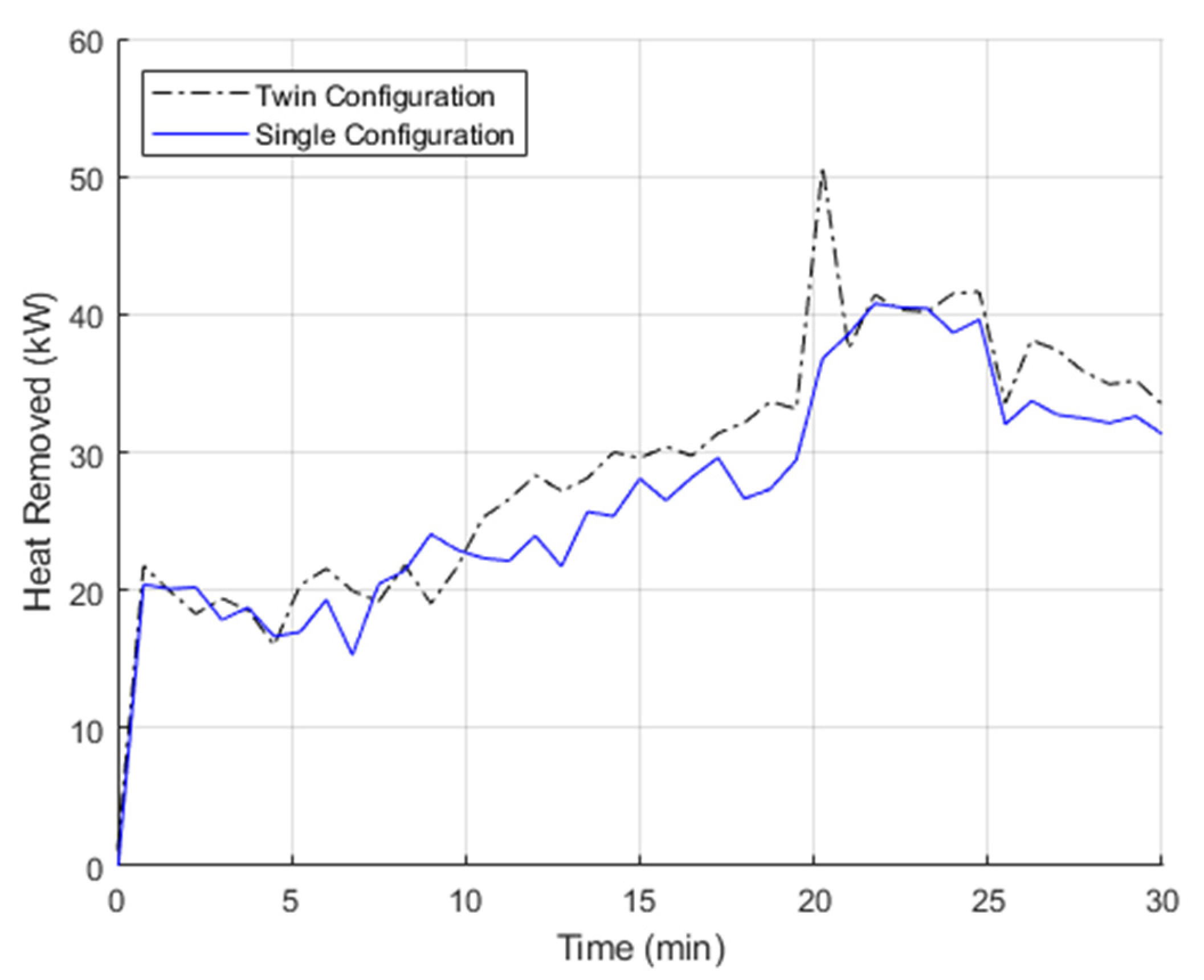
The steam inlet valve was used to provide a series of varied thermal loads while maintaining the desired coolant temperature using the stateflow controller discussed in Section 3. The stated heat values were designed to mimic a vehicle starting from rest. After a 20 min drive, an increased thermal load is scheduled for a 5 min interval before moving back to the initial value. This is observed in the heat removal plot shown in Figure 4. This approach shows the system behavior when a high thermal load is anticipated beforehand and/or emergency cooling is required at a moment’s notice. The experiment was repeated for two radiator configurations—twin (case A) vs. single radiators (case B). For case A, the additional radiator outlet valve and corresponding fans are closed until the higher cooling is required.
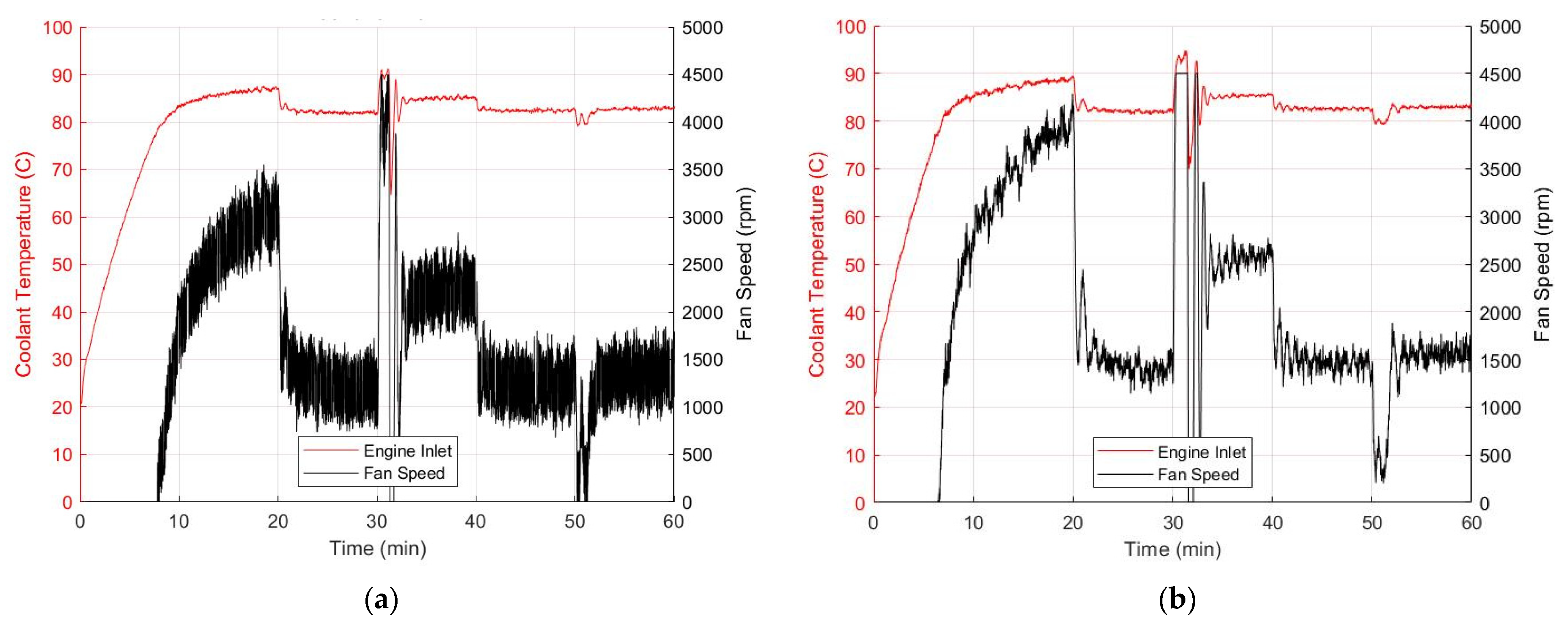
The engine coolant temperature and radiator fan speed data were logged to see the system behavior under different loads (refer to Figure 5). The setup acts like a single large radiator when both outlet valves are open throughout the 30 min period. Case A had a shorter warmup time (~10 min) and maintained the coolant temperature closer to the reference value ( °C). The sharp drop in temperature at 20 min is due to the sudden influx of the room temperature coolant from the inactive radiator. In contrast, case B caused overcooling and has a longer warmup time of about 13 min. Though both cases maintained the coolant temperature around the chosen reference value successfully, the proposed multi-radiator architecture had a much better temperature-tracking performance.
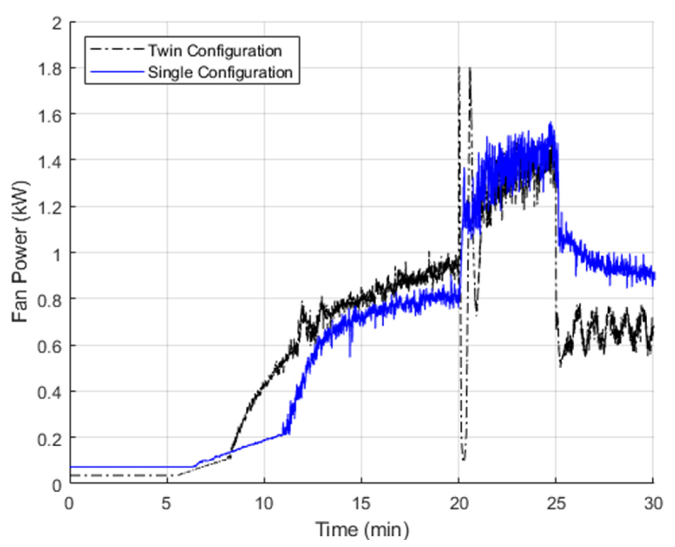
The energy efficiencies of the two configurations were studied based on the radiator fan power consumption. The coolant pump used for the experiment was oversized and used three-phase AC power. Figure 6 shows the net power consumption by all active fans during the test runs. The data, derived using the empirical relations, show that both cases had an almost similar power draw during the initial two phases, but the twin radiator design consumed ~0.3 kW less power during the last 5 min. Since most vehicles operate in the third phase, this power schedule is expected to provide significant energy savings for a variable-speed radiator fan cooling system. The fan energy requirement for the two cases is presented in Table 2 and shows 4.6% savings.
5. Controller Case Study
An effective automotive cooling system controller should minimize the actuator power consumption while also maintaining the reference temperature. To compare the temperature tracking performance, two other controllers were studied: sliding mode control (SMC) and classical. Sliding mode controllers are often chosen for their robustness and ability to handle sudden and significant system disturbances/parameter variations. Additionally, they provide excellent system state trajectory tracking along the chosen sliding surface (). A key factor for SMC implementation is the design of a nominal continuous controller that ensures asymptotic closed loop system stability, which can be designed using any known state feedback methods.
The control objective is to maintain the engine temperature at the set point ( = 85 °C) by eliminating the temperature error, . The radiator fans tend to be the major source of power consumption. Hence, the fan speed, ω, is taken as the primary control input. The coolant pump is controlled with a classical controller with proportional, , and integral, , gains. To study the control system thermal behavior, radiator one’s outlet valve will be fully open, while radiator two’s valve will be opened during high thermal loads, along with the corresponding electric fans. The radiator fans are all operated at the same speed when activated.
The performance of the two controllers was compared using a series of experimental tests with varying thermal loads. The experimental tests are divided into five phases depending on the time and heat loads that correspond to different operating scenarios, as listed in Table 3. For instance, the operating cycle includes idle–moderate–high thermal load cases such as stationary power generation demands. Note that radiator 2 is only used during the third and fourth phases, whereas radiator 1 is always active. The corresponding fans are also activated/deactivated accordingly. Figure 7 shows the engine temperature and corresponding fan speeds for the sliding mode and classic controllers, respectively.
As observed in Figure 7, the sliding mode controller has a quick response time of about 2 min and a low temperature offset (3–5 °C). However, the high fan oscillation is a major concern since it may lead to equipment damage/malfunction. The classical control has a better warmup time (5.2 min) but has a slightly higher response time of about 3.34 min. However, like the sliding mode control, it too had undesirable fan speed oscillations.
6. Conclusions
A vehicle cooling system with several parallel heat exchangers gives designers more flexibility in responding to shifting thermal loads and environmental circumstances. To show the system behavior using several electronic controlled actuators, a series of reproducible experiments were conducted. The tests demonstrate that the suggested architecture can function with just one radiator under low thermal loads (~20 kW) while activating the second radiator to accommodate larger engine torque situations (~40 kW). Furthermore, switching to a single-radiator arrangement under a lower thermal load scenario provided energy savings (~4.6%) and had a better temperature tracking and faster warmup time (~3 min improvement). The proposed technique can be used for emergency cooling to quickly bring the engine temperature within acceptable ranges, according to the experimental results. Since the sliding mode controller has a relatively low response time and offset but has significant fan speed oscillations, it is recommended for short-duration high-performance applications (e.g., formula racing). Similarly, the stateflow controller is suitable for applications with long run times (e.g., on-road passenger vehicles) since it has the lowest fan oscillation, along with a low offset. Lastly, the classic PI control is suitable as a middle ground, having the fastest warmup, slight fan oscillations, and a modest response.
Future work will involve studying the implementation of advanced nonlinear controls (e.g., model predictive control), the effects of ram air, and a cost–benefit analysis. The proposed scalable multi-heat exchanger design can be implemented for both stationary and mobile applications. Furthermore, by providing additional control variables, the design engineers can better control the component temperature while achieving an efficient energy performance.
Author Contributions
Conceptualization, Z.A.S. and J.R.W.; methodology, Z.A.S.; software, Z.A.S.; validation, Z.A.S. and J.R.W.; formal analysis, J.R.W.; investigation, Z.A.S.; resources, J.R.W.; data curation, Z.A.S.; writing—original draft preparation, Z.A.S.; writing—review and editing, J.R.W.; visualization, Z.A.S.; supervision, J.R.W.; project administration, J.R.W.; funding acquisition, J.R.W. All authors have read and agreed to the published version of the manuscript.
Funding
This research received no external funding.
Data Availability Statement
The experimental data can be requested from the corresponding author. A cloud share link will be provided on request.
Conflicts of Interest
The authors declare no conflict of interest.
Nomenclature
| Symbol | Description | Units | Symbol | Description | Unit |
| Temperature error | °C | Coolant temperature low | °C | ||
| Fan electric current draw | A | Coolant temperature maximum | °C | ||
| Pump electric current draw | A | Radiator temperature | °C | ||
| Integral gain for the sliding mode controller | - | Source temperature | °C | ||
| Integral gain for the classic control | - | Desired source temperature | °C | ||
| Integral gain for the coolant pump | - | Coolant temperature minimum | °C | ||
| Proportional gain for the sliding mode controller | - | Fan electric supply voltage | V | ||
| Proportional gain for the classic controller | - | Pump electric supply voltage | V | ||
| Proportional gain for the coolant pump | - | Source internal cavity volume | m3 | ||
| Sliding mode controller gain | - | Radiator internal cavity volume | m3 | ||
| Maximum air flow rate | kg/s | Air volumetric flow rate | m3/s | ||
| Maximum coolant flow rate | kg/s | Coolant volumetric flow rate | m3/s | ||
| Fan rotor speed | rpm | Net coolant flow rate | m3/s | ||
| Pump shaft speed | rpm | Outlet valve position | - | ||
| Fan electric power | kW | Effectiveness of the ith radiator | - | ||
| Pump electric power | kW | Coolant density | kg/m3 | ||
| Thermal load | kW | Input electric phase | Hz | ||
| Sliding surface | - | Applied electric phase | Hz | ||
| Ambient temperature | °C | Positive constant defining sliding surface | - | ||
| Coolant temperature high | °C | Radiator fan speeds | rpm |
References
- Rahman, S.; Sun, R. Robust Engineering of Engine Cooling System. In SAE Technical Paper 2003-01-0149; Society of Automotive Engineers: Detroit, MI, USA, 2003. [Google Scholar]
- Saidur, R.; Mekhilef, S.; Ali, M.B.; Safari, A.; Mohammed, H. Application of variable speed drive (VSD) in elecrical motor energy savings. Renew. Sustain. Energy Rev. 2012, 16, 543–550. [Google Scholar] [CrossRef]
- De Almeida, A.; Ferreira, F.; Both, D. Technical and Economical Considerations in the Application of Variable-Speed Drives with Electric Motor Systems. IEEE Trans. Ind. Appl. 2005, 41, 188–199. [Google Scholar] [CrossRef]
- Mudawwar, I.; Bharathan, D.; Kelly, K.; Narumanchi, S. Two-phase spray cooling of hybrid vehicle electronics. IEEE Trans. Compon. Packag. Technol. 2009, 32, 501–512. [Google Scholar] [CrossRef]
- Smith, K.; Earleywine, M.; Wood, E.; Neubauer, J.; Pesaran, A. Comparison of Plug-In Hybrid Electric Vehicle Battery Life Across Geographies and Drive Cycles. In SAE Technical Paper 2012-01-0666; Society of Automotive Engineers: Detroit, MI, USA, 2012. [Google Scholar]
- Kim, H.-I.; Shon, J.; Lee, K. A Study of Fuel Economy and Exhaust Emission according to Engine Coolant and Oil Temperature. J. Therm. Sci. Technol. 2013, 8, 255–268. [Google Scholar] [CrossRef]
- Lang, G.; Kitanoski, F.; Kussmann, C. Principal aspects and simulation of a hybrid demonstrator vehicle’s cooling system. In SAE Technical Paper 2007-01-3483; Society of Automotive Engineers: Detroit, MI, USA, 2007. [Google Scholar]
- Park, S.; Jung, D. Numerical Modeling and Simulation of the Vehicle Cooling System for a Heavy Duty Series Hybrid Electric Vehicle. In SAE Technical Paper 2008-01-2421; Society of Automotive Engineers: Detroit, MI, USA, 2008. [Google Scholar]
- Park, S.; Jung, D. Design of Vehicle Cooling System Architecture for a Heavy Duty Series-Hybrid Electric Vehicle Using Numerical System Simulations. J. Eng. Gas Turbines Power 2010, 132, 092802. [Google Scholar] [CrossRef]
- Węglarz, K.; Taler, D.; Taler, J. New non-iterative method for computation of tubular cross-flow heat exchangers. Energy 2022, 260, 124955. [Google Scholar] [CrossRef]
- Delouei, A.A.; Atashafrooz, M.; Sajjadi, H.; Karimnejad, S. The thermal effects of multi-walled carbon nanotube concentration on an ultrasonic vibrating finned tube heat exchanger. Int. Commun. Heat Mass Transf. 2022, 135, 106098. [Google Scholar] [CrossRef]
- Delouei, A.A.; Sajjadi, H.; Ahmadi, G. Ultrasonic vibration technology to improve the thermal performace of CPU water-cooling systems. Water 2022, 14, 4000. [Google Scholar] [CrossRef]
- De Donno, R.; Fracassi, A.; Ghidoni, A.; Morelli, A.; Noventa, G. Surrogate-Based Optimization of a Centrifugal Pump with Volute Casing for an Automotive Engine Cooling System. Appl. Sci. 2021, 11, 11470. [Google Scholar] [CrossRef]
- Wang, T.; Jagarwal, A.; Wagner, J.R.; Fadel, G. Optimization of an automotive radiator fan array operation to reduce power consumption. IEEE/ASME Trans. Mechatron. 2014, 20, 2359–2369. [Google Scholar] [CrossRef]
- Valaszkai, L.; Jouannet, B. Cooling system optimization for Euro4-EPA/02 heavy-duty trucks. SAE Int. J. Passeng. Cars-Mech. Syst. 2000, 109, 1510–1522. [Google Scholar]
- Bahman, A.S.; Blaabjerg, F. Optimization tool for direct water cooling system of high power IGBT modules. In Proceedings of the 18th European Conference on Power Electronics and Applications, Karlsruhe, Germany, 5–9 September 2016. [Google Scholar] [CrossRef]
- Su, C.Q.; Xu, M.; Wang, W.S.; Deng, Y.D.; Liu, X.; Tang, Z.B. Optimization of Cooling Unit Design for Automotive Exhaust-Based Thermoelectric Generators. J. Electron. Mater. 2015, 44, 1876–1883. [Google Scholar] [CrossRef]
- Du Plessis, G.E.; Liebenberg, L.; Mathews, E.H. The use of variable speed drives for cost-effective energy savings in South African mine cooling systems. Appl. Energy 2013, 111, 16–27. [Google Scholar] [CrossRef]
- Syed, Z.; Miller, R.; Wagner, J. Multiple Heat Exchangers for Automotive Systems-A Design Tool. In SAE Techncical Paper No. 2022-01-0180; Society of Automotive Engineers: Detroit, MI, USA, 2022. [Google Scholar]
Figure 1.
Architecture layout of the proposed multi-radiator thermal management system.

Figure 2.
Stateflow control architecture for the thermal management system.

Figure 3.
Experimental system at Clemson University testing facilities: (a) Twin radiators in parallel, (b) Swirl pot with servo motor-controlled outlet valves.
Figure 3.
Experimental system at Clemson University testing facilities: (a) Twin radiators in parallel, (b) Swirl pot with servo motor-controlled outlet valves.

Figure 4.
Heat removal rate vs. time for single- and two-radiator configurations.

Figure 5.
Coolant temperature (left axis) and fan/pump shaft speeds (right axis) with respect to time for (a) twin- and (b) single-radiator configurations.
Figure 5.
Coolant temperature (left axis) and fan/pump shaft speeds (right axis) with respect to time for (a) twin- and (b) single-radiator configurations.

Figure 6.
Radiator fan power consumption for twin- and single-radiator configurations.

Figure 7.
Engine coolant temperature profile with the respective fan speed for the (a) sliding mode and (b) classical controllers.
Figure 7.
Engine coolant temperature profile with the respective fan speed for the (a) sliding mode and (b) classical controllers.


Table 1.
Summary of system parameters.
| Symbol | Value | Units | Symbol | Value | Units |
|---|---|---|---|---|---|
| 2.1 | A | 30 | |||
| 80 | °C | 207 | |||
| 85 | °C | 3 | kg/s | ||
| 75 | °C | 1.5 | kg/s | ||
| 90 | °C | 60 | |||
| 70 | °C | 997 | kg/m3 |
Table 2.
Fan energy requirement for the two configurations integrated over the entire test cycle.
| Fan Energy (kWh) | |
|---|---|
| Twin Radiator (Case A) | 29.99 |
| Single Radiator (Case B) | 31.44 |
| Savings | 1.45 (4.6%) |
Table 3.
Experiment phases showing the thermal load and fan speeds for the controller performance evaluation.
Table 3.
Experiment phases showing the thermal load and fan speeds for the controller performance evaluation.
| Phase | Time (min) | Input Heat (kW) | Operating Scenario |
|---|---|---|---|
| 1 | 0–20 | ~40 | Moderate load |
| 2 | 21–30 | ~20 | Idle |
| 3 | 31–40 | ~60 | High load |
| 4 | 41–50 | ~40 | Moderate load |
| 5 | 51–60 | ~20 | Idle |
Disclaimer/Publisher’s Note: The statements, opinions and data contained in all publications are solely those of the individual author(s) and contributor(s) and not of MDPI and/or the editor(s). MDPI and/or the editor(s) disclaim responsibility for any injury to people or property resulting from any ideas, methods, instructions or products referred to in the content. |
© 2023 by the authors. Licensee MDPI, Basel, Switzerland. This article is an open access article distributed under the terms and conditions of the Creative Commons Attribution (CC BY) license (https://creativecommons.org/licenses/by/4.0/).
Share and Cite
MDPI and ACS Style
Syed, Z.A.; Wagner, J.R. Modeling and Control of a Multiple-Heat-Exchanger Thermal Management System for Conventional and Hybrid Electric Vehicles. Designs 2023, 7, 19. https://doi.org/10.3390/designs7010019
AMA Style
Syed ZA, Wagner JR. Modeling and Control of a Multiple-Heat-Exchanger Thermal Management System for Conventional and Hybrid Electric Vehicles. Designs. 2023; 7(1):19. https://doi.org/10.3390/designs7010019
Chicago/Turabian StyleSyed, Zaker A., and John R. Wagner. 2023. "Modeling and Control of a Multiple-Heat-Exchanger Thermal Management System for Conventional and Hybrid Electric Vehicles" Designs 7, no. 1: 19. https://doi.org/10.3390/designs7010019