1. Introduction
Prostheses can be used as visual elements that primarily serve to disguise a missing limb. In addition, simple mechanisms can be used to hold or grasp objects [
1,
2]. With the development of technology, fully robotic replacements of the lower and upper limbs have been developed. Advanced construction and high-tech materials are used, which are light and, at the same time, mechanically resistant. Thanks to this perfect combination, it is possible to prepare a fully functional prosthesis that will function similarly to a natural human limb. Unfortunately, not everyone can financially afford these sophisticated prostheses, which usually process signals from muscles, known as electromyography (EMG) [
3,
4,
5,
6].
Even the best robotic prosthesis will not work by itself without precise control. In general, the same principles of control can be used for all people, but in real life, many circumstances enter into it, which jam the received signal, and specific control errors can occur [
7,
8]. Many scientists are involved in acquiring, filtering and transforming signals from muscles (EMG), which in most cases are used to control robotic prostheses. They are trying to use the possibly most accessible system of sensing and processing the signal that will be economically advantageous to them [
9,
10]. EMG is also successfully used in rehabilitation, where muscle interaction can be sensed during the rehabilitation of an injured limb. Furthermore, kinematic sensors can be used which can support the EMG results. The use of this technique leads to the expansion of possibilities in assistive and rehabilitation robotics [
11,
12]. These techniques can also be supported by augmented and virtual reality [
13].
With the spread of technology to the general public comes a price reduction. In particular, the use of additive technology became widespread in prosthetics, where affordable robotic prostheses could even be manufactured at home. There are many open-access projects where functional robotic hands can be made at a reasonable price. However, the long-term usability and especially the functionality of prostheses produced in this way are often limited. Often, when grasping objects, the precision of the movement of the individual fingers of the prosthetic hand does not matter. This is mainly about grasping larger objects or showing certain gestures. To eliminate these shortcomings of the affordable prosthetic hand, various constructions endeavor to grasp objects precisely [
14,
15,
16].
Bahari et al. [
17], in their prosthetic hand design, use gears to transmit movement to the fingers. They describe the kinematics of finger movement, but nothing is written about the accuracy of individual finger movements [
17]. Sanchez-Velasco et al. [
18] used a similar design with gears as Bahari et al. [
17]. The low-cost robotic hand is controlled by EMG. It was found that this design can precisely control individual parts of the hand. However, the authors do not mention the wear of moving parts and the possible changes in the accuracy of finger movements due to use [
18]. Silveira Romero et al. [
19] and Weiner et al. [
20] used strings/wires to move individual fingers. In both studies, the designs of the prosthetic hand are described, but there is no mention of the accuracy of the movement of the individual fingers right after the production in comparison to the accuracy after a certain time of use [
19,
20]. He et al. [
21] and Narumi et al. [
22] also used strings/wires in their studies, but used the anatomical construction of the fingers. As in previous cases, they verified the functionality of the proposed solution, but the issue of use and subsequent wear of functional parts was not addressed at all in these studies [
21,
22].
It was found that there are many design solutions for how to make a low-cost prosthetic hand [
23,
24,
25,
26,
27]; however, in this study, it was possible to find a modified design solution that makes it possible to reliably imitate the physiological movement of the fingers. The accuracy of the fingers was measured by kinematics sensors placed on the distal phalange of each finger. The accuracy of finger movements was evaluated right after production and after a certain period of use to determine whether the affordable prosthetic hand designed in this study can also be used in a real application. This study also highlights the lack of a universal comparative test that simply establishes the long-term functionality of affordable prostheses.
2. Materials and Methods
This paper deals with the design and long-term testing of an affordable transradial five-finger prosthesis replicating the movements of a real human hand. The design of a prosthetic hand and all its moving elements were designed in CAD (NX 2022, Siemens). During the construction of the prosthesis, increased demands were placed on simplicity, repairability in the event of electronic failure or damage of moving parts, and manufacturability using the globally widespread and affordable FDM (Fused Deposition Modeling) type additive technology. All parts were fabricated on an FDM 3D printer (Fortus 900mc, Stratasys, Ltd., Rechovot, Izrael) A 1.75 mm-diameter acrylonitrile butadiene styrene (ABS-M30, Stratasys, Rechovot, Izrael) filament was used in the production process. This material is lightweight while still having sufficient strength and toughness to be used in structural applications where the load does not exceed the material’s limits.
The actual print time for all required components was 32 h at 0.178 mm layering.
An important aspect of the design was the choice of electronics. One of the basic features of affordable hand prostheses is the availability of spare parts. Particularly due to the low price and good availability, Arduino, which is enjoying ever-increasing popularity, especially in do-it-yourself projects, was chosen as the main control element. Although only commercially available components were used in the design of the electronics of the prosthesis, a custom-made circuit board of composite material FR-4 1.5/Cu 35 um was required.
All of the electronic components needed to assemble the prosthetic hand are listed below:
1× Arduino Nano R3 ATmega328P
6× servomotors MG995
1× voltage regulator LM2596
1× LiPol 2S 7.4 V/3000 mAh
1× custom-made circuit board
3. The Design of Transradial Prosthesis
3.1. CAD Design and Assembly of the Transradial Prosthesis
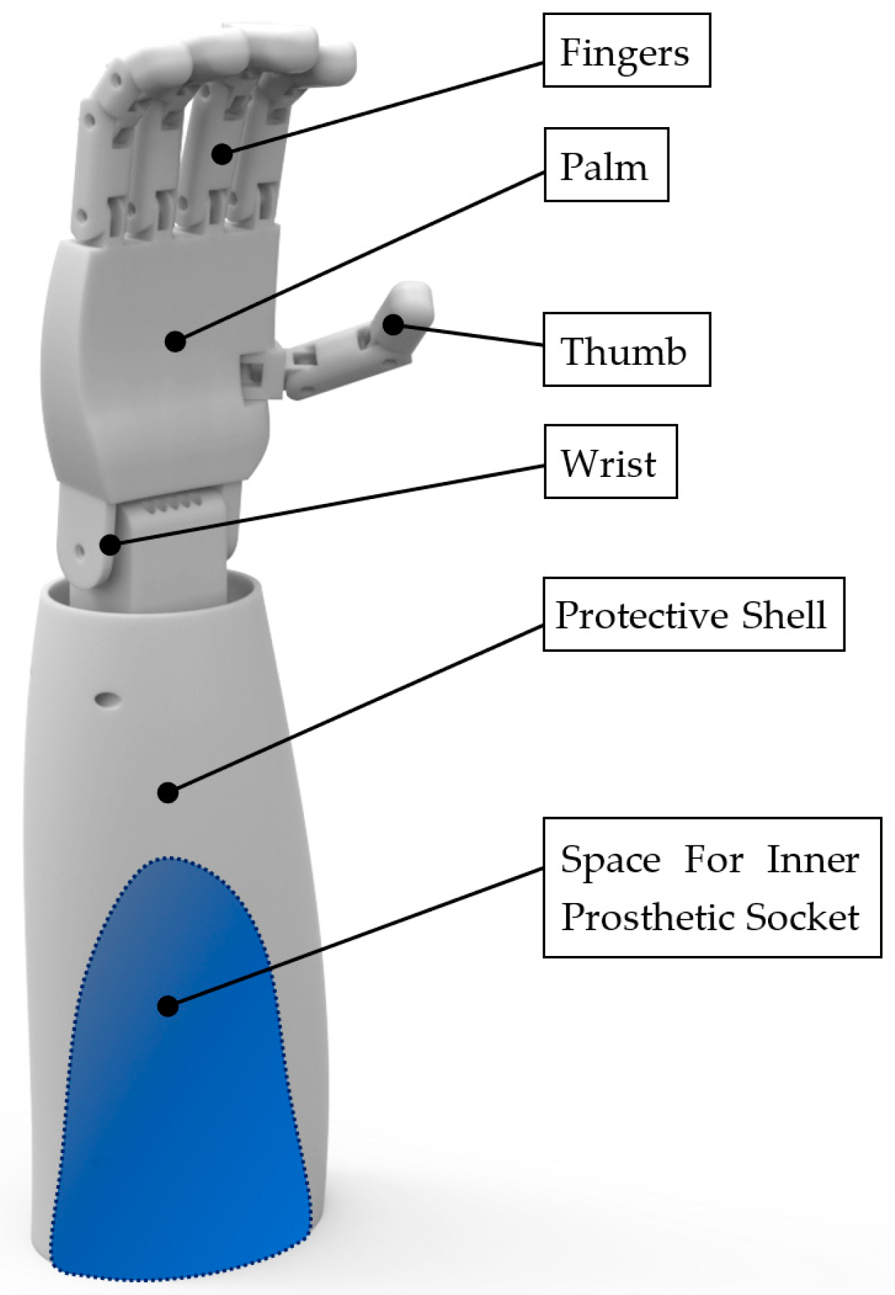
The transradial prosthesis in
Figure 1 is composed of a palm with fingers, a thumb, a wrist, a forearm, and a protective shell. The protective shell contains an inner prosthetic socket manufactured specifically for the prosthesis user. The design of the prosthesis is based on measurements taken on the real hand of a volunteer (male, 34 years old).
The CAD design of the prosthesis presented in this article is based on verified and tested designs of affordable wire-controlled prostheses, often manufactured using 3D printing [
15,
16,
17,
18,
19,
20,
21]. An increased effort was focused on the prosthesis’ CAD design’s simplicity, repairability in the case that moving parts were damaged, and full manufacture-ability of non-electronic components using FDM 3D printing technology. This technology enables the production of complex external and internal shapes, including hollow structures.
During the CAD design, the basic rules for creating parts for trouble-free and support-free FDM 3D printing were strictly followed (e.g., the 45-degree rule). The prosthesis’s main control wires can be hidden in the smooth guiding channels produced by 3D printing. These channels are shown in
Figure 2.
To prevent potential damage to these components brought on by the usage of the prosthesis, all mechanical and electrical prosthesis control components were placed inside the protective shell, above the cavity for the inner socket. The surface of the prosthesis was designed to be smooth, with recessed screw joints and the smallest possible gaps between moving parts. To ensure the smoothest possible movement of the prosthesis, all movable elements of the prosthesis were first machine sandblasted with a fine abrasive to eliminate the layering created by 3D printing. Additionally, all parts were manually sanded using sandpaper with gradually increasing grit.
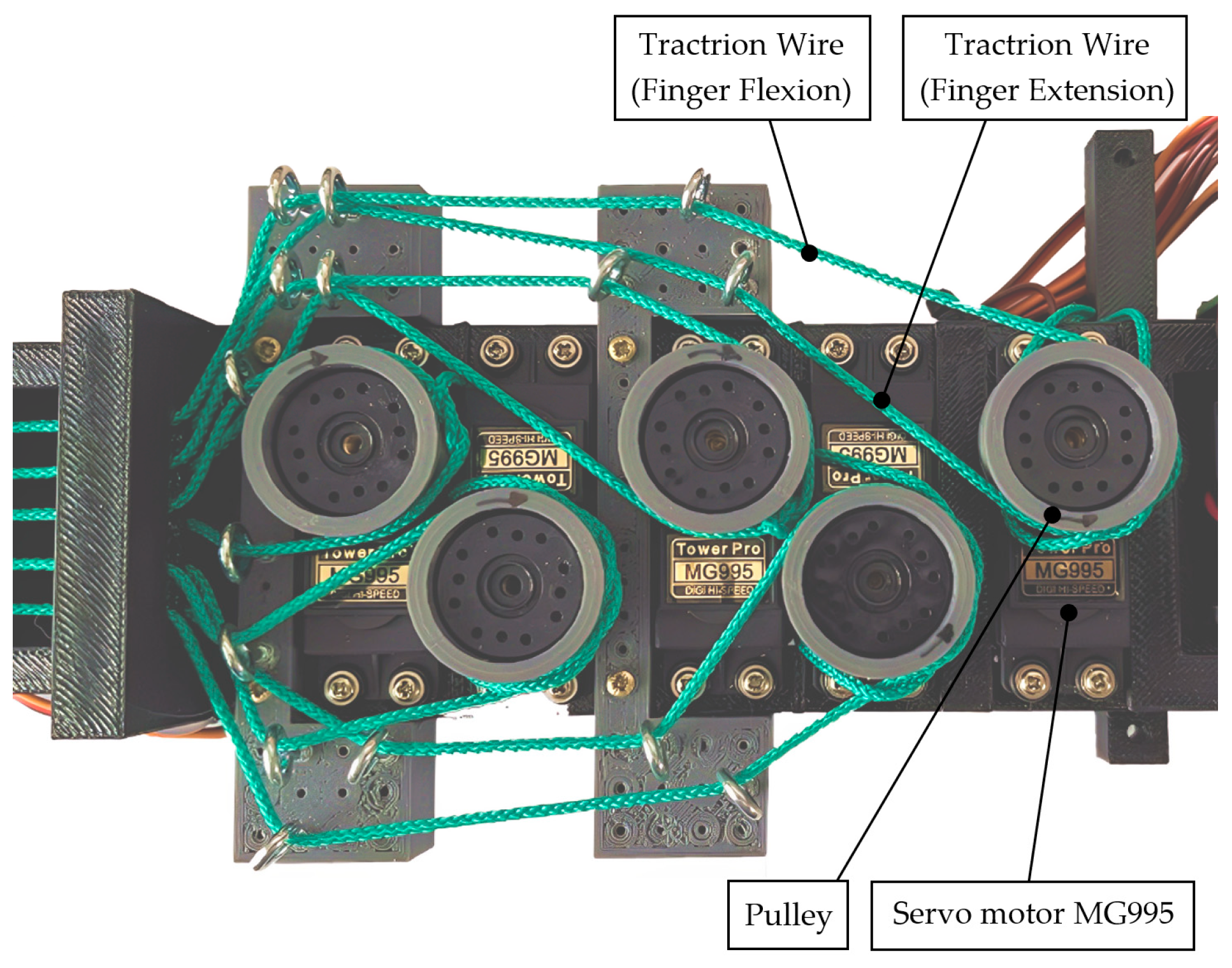
A set of two individual traction wires manufactured from polypropylene with the trade name PPV 1 controls the finger movements. One controls the flexion of the finger, while the other controls its extension.
Figure 3 and
Figure 4 show the connection of traction wires between the control servo motor and the last segment of each finger (distal phalange).
The upper limb prosthesis described in this article consists of 24 individual parts. The individual segments of the fingers are interconnected by screw connections. Six MG995 servo motors equipped with turning pulleys handle the flexion and extension of the fingers and wrist. When set correctly, these servo motors enable a very gentle but also a very firm grasp of differently shaped objects.
A rubber cover was added to one side of the wire in each finger to enable a smooth transition back to the straightened position. This adjustment resulted in a natural, smooth movement when bending the fingers compared to a non-rubbed surface. Postprocessing of the 3D-printed parts and assembly of the prosthesis took about 6 h. The transradial prosthesis after assembly is shown in
Figure 5.
3.2. Electronic Design of the Transradial Prosthesis
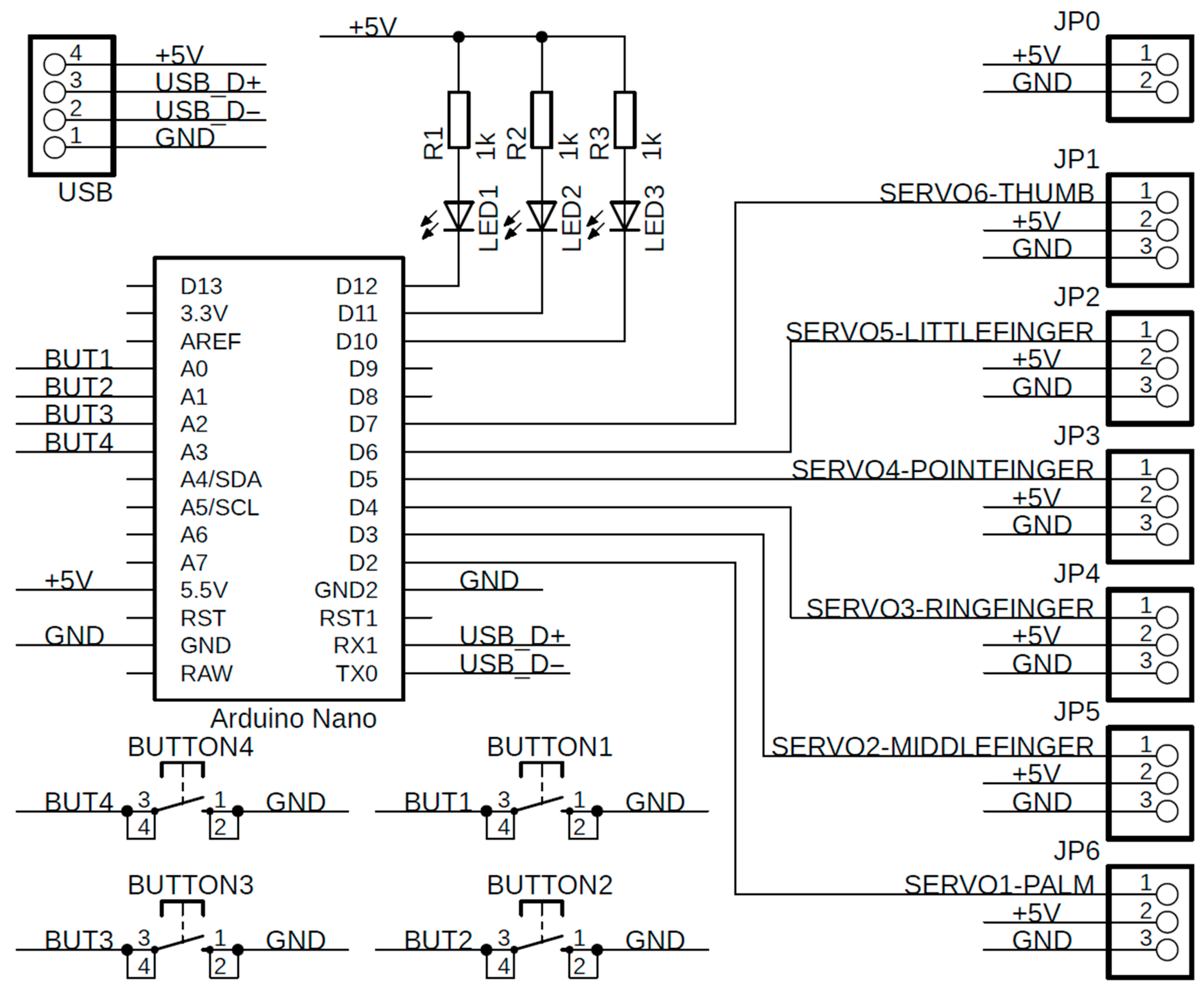
The Arduino platform, namely the Arduino Nano R3 and its ATmega328P microcontroller, served as the basis for the electronic design of the prosthetic hand. The mainboard was chosen for its low price, simple design, and sufficient input and output ports. Additionally, it runs on 5 V and includes 6 PWM (pulse–width modulation) outputs, which are appropriate for connecting servomotors and external communication by USB.
However, the mainboard lacks additional pins for the system’s other parts, including servomotors, voltage regulators, buttons, and LEDs. This issue led to the creation of a special circuit board that had all the required parts and terminals. This board is mostly used for connecting servomotors, which need three pins. These pins are identified as GND, Signal, and 5 V. Four buttons and three LEDs are located on the custom-made circuit board. Each button is linked to the microcontroller’s analogue input and serves to launch the selected program kept in the prosthetic hand memory.
Figure 6 shows the electric schema draft of the custom-made circuit board.
The whole system is powered by an LM2596 voltage regulator with a segmented LED display which can handle input voltages from 7 V up to 40 V, and it can regulate it into 5 V, which is suitable for the microcontroller and servomotors. The primary power source is a LiPol battery, specifically a LiPol 2S 7.4 V/3000 mAh battery with sufficient voltage and energy for reliable operation for at least two hours without external power. As mentioned before, the device used for finger movement is called an MG995 servomotor with a metal gearbox with the possibility of rotation from 0° to 180°. The torque of the servomotor is approximately 1.2749 Nm, which is strong enough to replicate the movement and the strength of a real human hand.
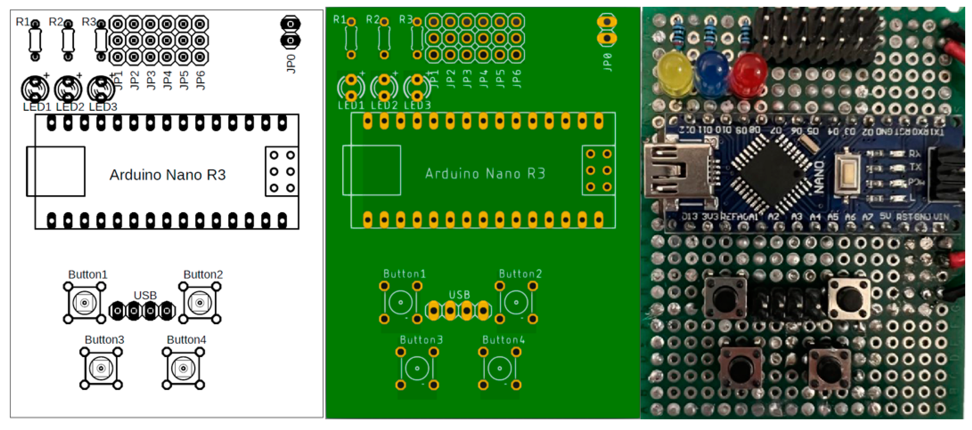
The electronics were designed in SW Eagle and Fusion 360 (both Autodesk) specifically for free personal use. The final design of the custom printed circuit board was realized using a universal prototyping board with manual placement and soldering. The entire process of design, visualization and final production of a custom board is shown in
Figure 7.
3.3. Manufacturing of a Glove for Prosthesis Control
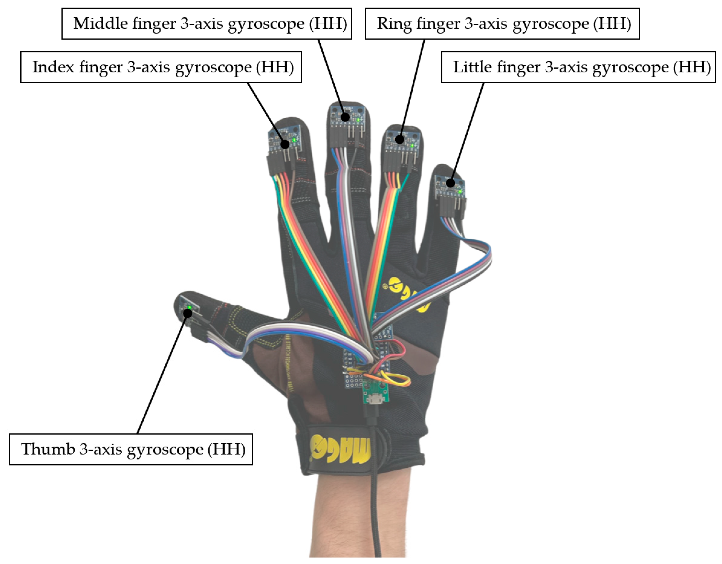
The sensor part which senses the movement of the individual human fingers must be placed directly on the human hand. The most comfortable and quick way to put on all needed electronic components involves the special glove, where all required components are placed and connected in one piece. To minimalize the size, number and weight of all electronic components, the microcontrollers WeMos D1 Mini with the 3-axis gyroscope MPU-6050 were chosen for the final design of the glove.
As mentioned previously, the angle of each finger is measured separately by the MPU-6050, and the measured angle is transmitted to the WeMos D1 Mini within the I2C serial communication bus. Only two devices can transmit data simultaneously using the I2C protocol. When several devices are connected to one I2C bus, the enable signal must be implemented for all devices. Due to this problem, each MPU-6050 has a pin called the AD0, which enables communication within the I2C. This pin is used in the program to enable the address line for the individual MPU-6050.
In total, there are six MPU-6050s, one for each finger and one for the reference point placed on the back of the hand. The main program periodically checks the actual angle between the MPU-6050 placed on the finger and the reference MPU-6050 placed on the back of the hand. The subtraction of these angles gives the intended angle of each finger. The described glove is shown in
Figure 8.
The WeMos D1 Mini has a very minimalistic design, and it requires a I2C communication bus and a USB connector for data transmission to the prosthetic hand. Another additional board was created for the connection between the MPU-6050 and the WeMos D1 Mini because each MPU-6050 needs to be connected by the five wires, namely SDA, SCL, VCC, GND, and AD0. The MPU-6050 was fastened to each distal phalanx and the WeMos D1 Mini was affixed to the hand’s dorsal side. These components were linked by flexible wires.
The primary communication method for data transmission to the prosthetic hand was hardware serial communication to avoid the unnecessarily complicated USB communication produced by the driver placed on the WeMos D1 Mini.
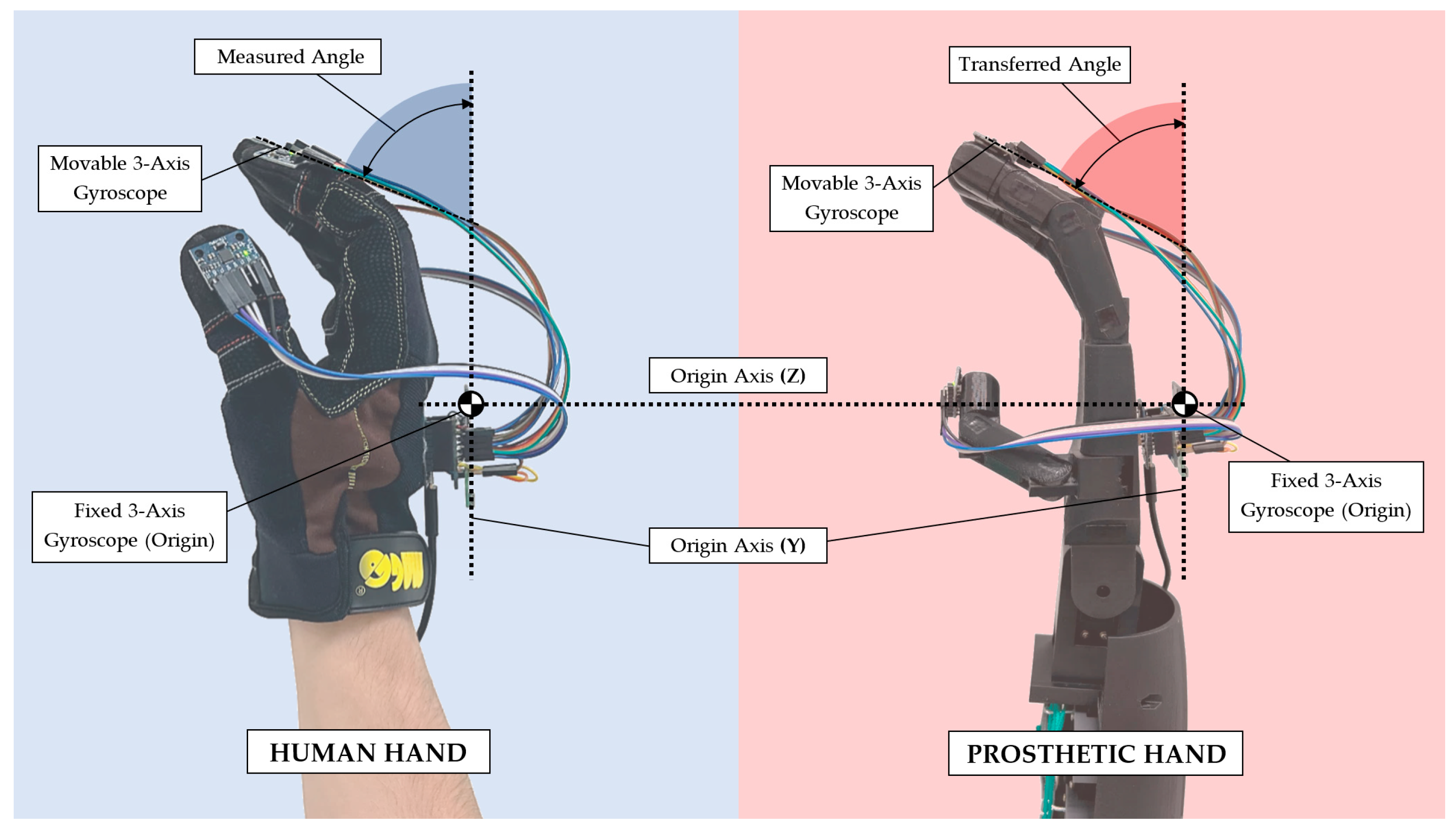
4. The Main Experiment
The main experiment was done to test the durability and accuracy of the moving fingers of an affordable transradial prosthesis. As mentioned before, the prosthetic hand should be able to simultaneously replicate the finger movement of a human hand using several sensors placed on each finger and the back of the human hand (
Figure 9).
The first part of the experiment was focused on the movement replication done by the glove, with the sensors periodically measuring and calculating the current angle of each independent finger on the human hand. The final information about the position of the fingers is transmitted to the prosthetic hand within the serial hardware interface. To adapt to the speed of the servomotor, there is a software delay between each command transmitted to each independent servomotor set to 100 ms. Each servomotor has enough time to reach the destination given by sensors with the mentioned time delay. Moreover, the value is also sufficient for this research due to the emphasis on accuracy rather than speed.
The maximal and minimal angle of each finger is measured electronically by the referenced MPU-6050 that is placed on the human hand. The signal generated by the measured angles is used as an input signal to control the prosthetic hand’s servomotors. As mentioned previously, this article should prove the proposed concept of movement replication from a real human hand to a prosthetic hand. Scanning and measuring the data can increase the accuracy and the final statement of this experiment. These data should be sufficient to prove the intended concept, design, and connection.
The second part of the experiment is focused on the durability and accuracy of long-term continuous testing. The accuracy of the constructed prosthetic hand after the assembly was measured by the MPU-6050 sensors. Initial measurements were made for each finger at distal phalange angles of 0, 40, and 80 degrees. Each angle was measured 15 times.
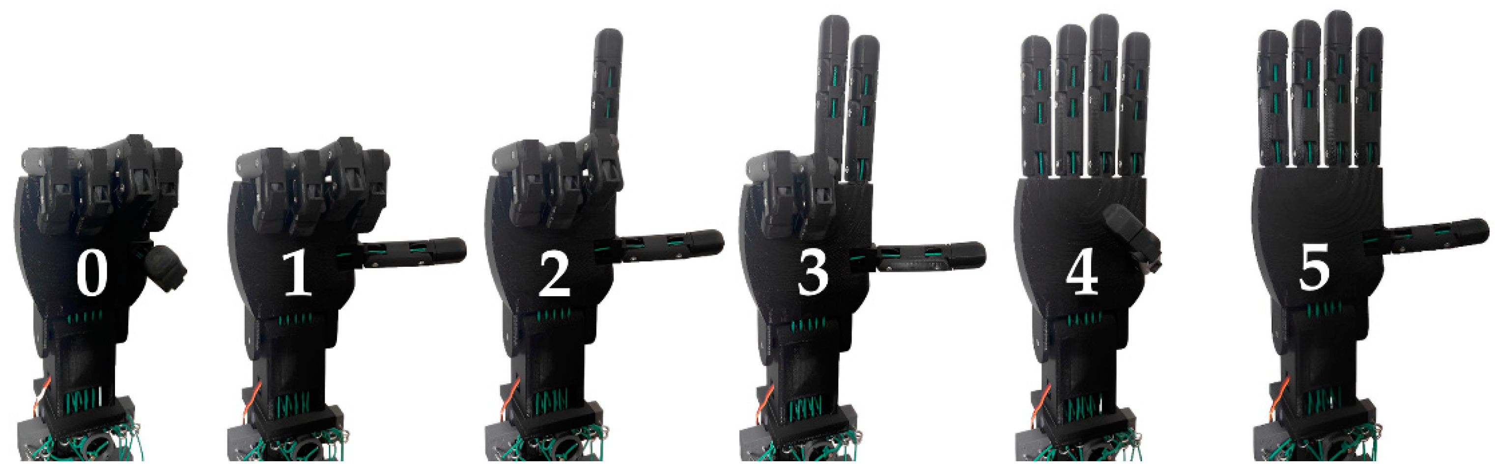
To verify the long-term accuracy of the prosthetic grip, a sequence of repetitive movements combining both extreme finger positions—flexion and extension—was subsequently designed. This sequence simulates finger counting, also known as dactylonomy. This counting system is widespread in places such as Central Europe, for example. The description of the involvement of individual fingers during finger-counting is shown in
Table 1. [
28]
Figure 10 displays the finger counting executed on the prosthetic hand. Over the course of 30 days, the prosthesis performed 100,000 uninterrupted cycles of this continuously repeating counting sequence. After the test sequence was finished, the prosthetic hand was remeasured in the same way—with the same angle settings of each distal phalanx at 0, 40, and 80 degrees.
5. Results and Discussion
The main emphasis of this article is to test the durability and accuracy of an affordable transradial prosthesis after intense long-term use. The prosthetic hand’s accuracy was measured twice—once immediately after the assembly of the prosthetic hand and once after a long-term finger counting sequence. This test should clarify the accuracy and the durability of prosthetic hand parts in real life.
Verification of the Accuracy of the Prosthetic Hand before and after Long-Term Test
Before the long-term testing, the initial measurements were undertaken to define the initial accuracy of the assembled prosthetic hand. The angle of each finger was tested and measured by setting the intended angle to 0, 40, and 80 degrees. All measurements were performed by the MPU-6050 set and the WeMos D1 Mini. To simulate the long-term continuous testing, a western world counting system from zero to five was established for 100,000 cycles.
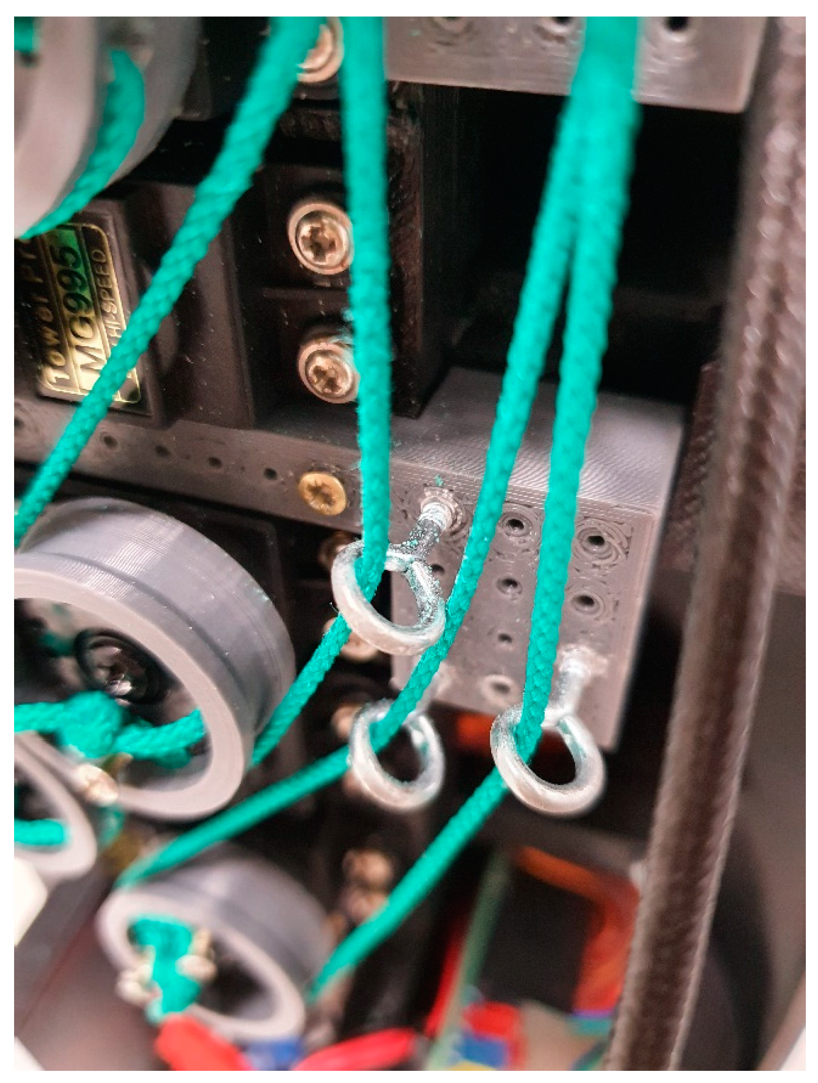
The long-term test was considered successful since no malfunction or mechanical damage to the prosthesis was observed. During this approximately 30-day test phase, no visible or quantifiable differences in motion control were noticed (e.g., lengthening or destruction to traction wires, damage to electronics or servo motors). The nature of the dam-age to all exposed parts is purely cosmetic and has no effect on the prosthesis’s function.
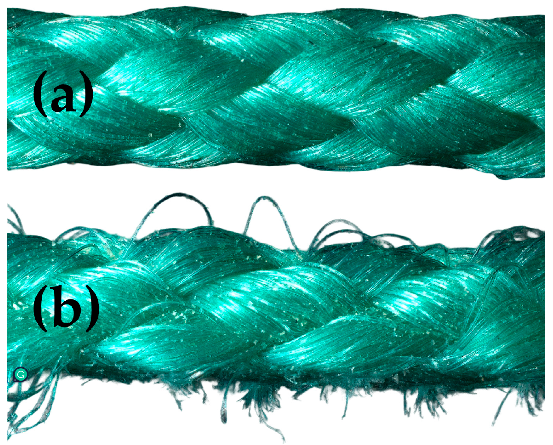
As a result of the tensioning mechanism’s design (shown in
Figure 11), the most visible damage occurred at several locations along the traction wire loop. Friction between the traction wire and the tensioning metal eye created burrs and chipping of the wire particles.
Figure 12 depicts the condition of the tension wires before and after the long-term test.
Future studies should focus on tensioning system modifications, such as the use of bearings or guide covers, which might significantly minimize wear.
No mechanical damage to the rotating pulleys was observed during a long-term test. Contact between the 3D-printed pulleys and the traction wire resulted in no burrs or chip-ping. The 3D-printed pulleys can be advantageously used in the production of prostheses with a similar design.
Furthermore, no increased radial or axial looseness in the finger joints was observed. The screw connections in the prosthesis joints were verified to not be able to be loosened by a torque wrench. The screws were adjusted to the same torque both before and after the long-term test. Although no greater inaccuracy in the positioning of the thumb was detected by the measurement, greater looseness in the thumb positioning was observed after the test compared to the other fingers. The increased looseness is most likely due to the thumb joints’ different construction from the rest of the fingers. The following work should concentrate on enhancing the design of the thumb joints.
The minimal differences in the position of the finger end links before and after the test also indicate that there was also no damage to the servomotors. The accuracy of finger positioning remained almost unchanged after the long-term test. Finger position accuracy was measured after the test under identical conditions as before.
Table 2,
Table 3 and
Table 4 show the results of both measures.
During the testing of the prosthesis design, deficiencies in grip strength and repeatability were found—the distal phalanges of the fingers were not provided with an anti-slip surface. In normal use, mainly components with smooth surfaces such as glasses or bottles slipped in different grip types (spherical grip, tip pinch). In the design of the next version of this prosthesis, the distal phalanxes will be supplemented with an anti-slip layer made by multi-component 3D printing from a flexible material.
The purpose of this rigorous test was to confirm the prosthesis’ accuracy and usability over time. The result of the test is a verification of the functionality of the prosthetic hand after 100,000 cycles. The accuracy of finger positioning deteriorated only minimally. There was minimal wear on functional parts such as wires and moving parts of the fingers (joints).
6. Conclusions
It was proven that the proposed affordable transradial prosthesis solution is fully functional even after a long-term test when the prosthetic hand worked continuously for 30 days without any damage. Based on the measurement of the accuracy of the finger position before and after the long-term test, it was found that the deviation from the finger position worsened only minimally. There was only minimal wear on the functional parts due to finger positioning cycles. Although significant deviations from the required angles of all five fingers were not measured, a certain looseness was observed in the positioning of the thumb which is under the most strain. This indicates that it is advisable to prepare a universal comparative test that would be able to evaluate the long-term functionality of the transradial prosthesis according to various criteria.
In the next study, we will focus on the improvement of thumb movements to avoid excessive wear and tear. It is also needed to reduce the weight of this transradial prosthesis, which will be the biggest goal of the next study. In this study, long-term operability was verified, although at the expense of weight, which will be reduced to a minimum in the next version.
Author Contributions
Conceptualization, A.M. and V.M.; Methodology, Z.K. and P.S.; Validation, M.K. (Michaela Karhankova) and M.K. (Matej Krupciak); Formal analysis, J.M. and P.S.; Resources, M.K. (Michaela Karhankova) and Z.K.; Writing—original draft preparation, Z.K. and V.M.; Writing—review and editing, A.M., M.K. (Matej Krupciak) and J.M.; Supervision, R.J.; Project administration, A.M. All authors have read and agreed to the published version of the manuscript.
Funding
This research was funded by the Internal Grant Agency of Tomas Bata University supported under project No. IGA/CebiaTech/2023/001.
Institutional Review Board Statement
Not applicable.
Informed Consent Statement
Not applicable.
Data Availability Statement
The data presented in this study are available on request from the corresponding author.
Conflicts of Interest
The authors declare that they have no conflict of interest.
References
- Maat, B.; Smit, G.; Plettenburg, D.; Breedveld, P. Passive Prosthetic Hands and Tools: A Literature Review. Prosthet. Orthot. Int. 2018, 42, 66–74. [Google Scholar] [CrossRef] [PubMed] [Green Version]
- Dechev, N.; Cleghorn, W.L.; Naumann, S. Multiple Finger, Passive Adaptive Grasp Prosthetic Hand. Mech. Mach. Theory 2001, 36, 1157–1173. [Google Scholar] [CrossRef]
- Ribeiro, J.; Mota, F.; Cavalcante, T.; Nogueira, I.; Gondim, V.; Albuquerque, V.; Alexandria, A. Analysis of Man-Machine Interfaces in Upper-Limb Prosthesis: A Review. Robotics 2019, 8, 16. [Google Scholar] [CrossRef] [Green Version]
- Brack, R.; Amalu, E.H. A Review of Technology, Materials and R&D Challenges of Upper Limb Prosthesis for Improved User Suitability. J. Orthop. 2021, 23, 88–96. [Google Scholar] [CrossRef] [PubMed]
- Viteckova, S.; Kutilek, P.; de Boisboissel, G.; Krupicka, R.; Galajdova, A.; Kauler, J.; Lhotska, L.; Szabo, Z. Empowering Lower Limbs Exoskeletons: State-of-the-Art. Robotica 2018, 36, 1743–1756. [Google Scholar] [CrossRef]
- Janos, R.; Sukop, M.; Semjon, J.; Vagas, M.; Galajdova, A.; Tuleja, P.; Koukolová, L.; Marcinko, P. Conceptual Design of a Leg-Wheel Chassis for Rescue Operations. Int. J. Adv. Robot. Syst. 2017, 14, 1–9. [Google Scholar] [CrossRef] [Green Version]
- Nam, D.; Cha, J.M.; Park, K. Next-Generation Wearable Biosensors Developed with Flexible Bio-Chips. Micromachines 2021, 12, 64. [Google Scholar] [CrossRef]
- Antonelli, M.G.; Zobel, P.B.; Durante, F.; Zeer, M. Modeling-Based EMG Signal (MBES) Classifier for Robotic Remote-Control Purposes. Actuators 2022, 11, 65. [Google Scholar] [CrossRef]
- He, Z.; Qin, Z.; Koike, Y. Continuous Estimation of Finger and Wrist Joint Angles Using a Muscle Synergy Based Musculoskeletal Model. Appl. Sci. 2022, 12, 3772. [Google Scholar] [CrossRef]
- Jiang, X.; Merhi, L.K.; Xiao, Z.G.; Menon, C. Exploration of Force Myography and Surface Electromyography in Hand Gesture Classification. Med. Eng. Phys. 2017, 41, 63–73. [Google Scholar] [CrossRef]
- Ali, A.M.M.; Kadir, K.; Billah, M.M.; Yosuf, Z.; Janin, Z. Development of Prismatic Robotic Arms for Rehabilitation by Using Electromyogram(EMG). In Proceedings of the 2018 IEEE 5th International Conference on Smart Instrumentation, Measurement and Application, ICSIMA 2018, Songkhla, Thailand, 28–30 November 2018. [Google Scholar] [CrossRef]
- Zhou, H.; Zhang, Q.; Zhang, M.; Shahnewaz, S.; Wei, S.; Ruan, J.; Zhang, X.; Zhang, L. Toward Hand Pattern Recognition in Assistive and Rehabilitation Robotics Using EMG and Kinematics. Front. Neurorobot. 2021, 15, 659876. [Google Scholar] [CrossRef]
- Sanford, S.; Collins, B.; Liu, M.; Dewil, S.; Nataraj, R. Investigating Features in Augmented Visual Feedback for Virtual Reality Rehabilitation of Upper-Extremity Function through Isometric Muscle Control. Front. Virtual Real. 2022, 3, 943693. [Google Scholar] [CrossRef]
- Tamilselvi, R.; Merline, A.; Parisa Beham, M.; Vijay Anand, R.; Shre Karthik, M.; Uthayakumar, R.H. EMG Activated Robotic Arm for Amputees. In Proceedings of the 2nd International Conference on Inventive Systems and Control, ICISC 2018, Coimbatore, India, 19–20 January 2018. [Google Scholar] [CrossRef]
- Wang, Y.; Tian, Y.; She, H.; Jiang, Y.; Yokoi, H.; Liu, Y. Design of an Effective Prosthetic Hand System for Adaptive Grasping with the Control of Myoelectric Pattern Recognition Approach. Micromachines 2022, 13, 219. [Google Scholar] [CrossRef]
- Akhmadeev, K.; Rampone, E.; Yu, T.; Aoustin, Y.; Carpentier, E.L. A Testing System for a Real-Time Gesture Classification Using Surface EMG. In Proceedings of the 20th World Congress of the International Federation of Automatic Control, Toulouse, France, 9–14 July 2017. [Google Scholar] [CrossRef]
- Bahari, M.S.; Jaffar, A.; Low, C.Y.; Jaafar, R.; Roese, K.; Yussof, H. Design and Development of a Multifingered Prosthetic Hand. Int. J. Soc. Robot. 2012, 4, 59–66. [Google Scholar] [CrossRef]
- Sánchez-Velasco, L.E.; Arias-Montiel, M.; Guzmán-Ramírez, E.; Lugo-González, E. A Low-Cost EMG-Controlled Anthropomorphic Robotic Hand for Power and Precision Grasp. Biocybern. Biomed. Eng. 2020, 40, 221–237. [Google Scholar] [CrossRef]
- Silveira Romero, R.C.; Machado, A.A.; Costa, K.A.; Reis, P.H.R.G.; Brito, P.P.; Vimieiro, C.B.S. Development of a Passive Prosthetic Hand That Restores Finger Movements Made by Additive Manufacturing. Appl. Sci. 2020, 10, 4148. [Google Scholar] [CrossRef]
- Weiner, P.; Starke, J.; Hundhausen, F.; Beil, J.; Asfour, T. The KIT Prosthetic Hand: Design and Control. In Proceedings of the 2018 IEEE/RSJ International Conference on Intelligent Robots and Systems (IROS), Madrid, Spain, 1–5 October 2018. [Google Scholar] [CrossRef]
- He, Z.; Yurievich, R.R.; Shimizu, S.; Fukuda, M.; Kang, Y.; Shin, D. A Design of Anthropomorphic Hand Based on Human Finger Anatomy. In Proceedings of the 2020 International Symposium on Community—Centric Systems (CcS), Tokyo, Japan, 23–26 September 2020. [Google Scholar] [CrossRef]
- Narumi, S.; Huang, X.; Lee, J.; Kambara, H.; Kang, Y.; Shin, D. A Design of Biomimetic Prosthetic Hand. Actuators 2022, 11, 167. [Google Scholar] [CrossRef]
- Borja, G.; De los Rios, E.; Dominguez, M.; Fabregas, J.; Ledesma, J.; Barrios, D. Design of a Multifunctional Low-Cost Hand Prosthesis. In Proceedings of the 2022 IEEE Conference on Global Medical Engineering Physics Exchanges/Pan American Health Care Exchanges (GMEPE/PAHCE), Panama City, Panama, 21–26 March 2022. [Google Scholar] [CrossRef]
- Hocaoglu, E.; Patoglu, V. Design, Implementation, and Evaluation of a Variable Stiffness Transradial Hand Prosthesis. Front. Neurorobot. 2022, 16, 789210. [Google Scholar] [CrossRef]
- Lee, M.Y.; Lee, S.H.; Leigh, J.H.; Nam, H.S.; Hwang, E.Y.; Lee, J.Y.; Han, S.; Lee, G. Functional improvement by body-powered 3D-printed prosthesis in patients with finger amputation Two case reports. Mediav 2022, 101, e29182. [Google Scholar] [CrossRef]
- Tinoco-Varela, D.; Ferrer-Varela, J.A.; Cruz-Morales, R.D.; Padilla-Garcia, E.A. Design and Implementation of a Prosthesis System Controlled by Electromyographic Signals Means, Characterized with Artificial Neural Networks. Micromachines 2022, 13, 1681. [Google Scholar] [CrossRef]
- Yurova, V.A.; Velikoborets, G.; Vladyko, A. Design and Implementation of an Anthropomorphic Robotic Arm Prosthesis. Technologies 2022, 10, 103. [Google Scholar] [CrossRef]
- Pika, S.; Nicoladis, E.; Marentette, P. How to order a beer: Cultural differences in the use of conventional gestures for numbers. J. Cross Cult. Psychol. 2009, 40, 70–80. [Google Scholar] [CrossRef]
| Disclaimer/Publisher’s Note: The statements, opinions and data contained in all publications are solely those of the individual author(s) and contributor(s) and not of MDPI and/or the editor(s). MDPI and/or the editor(s) disclaim responsibility for any injury to people or property resulting from any ideas, methods, instructions or products referred to in the content. |
© 2023 by the authors. Licensee MDPI, Basel, Switzerland. This article is an open access article distributed under the terms and conditions of the Creative Commons Attribution (CC BY) license (https://creativecommons.org/licenses/by/4.0/).


 ,
, 


