1. Introduction
The pressure hull of a deep-diving submarine is subject to perfectly symmetrical water pressure. Based on the principle that a symmetrical structure is most suited to the applicable load conditions, the pressure hull of a deep-sea submarine is often spherical in shape [
1,
2,
3].
Many research results have been published regarding the crushing and buckling characteristics and structural design of pressure hulls under severe loading conditions in the deep sea [
4,
5,
6,
7,
8]. Investigations are being conducted on the crushing and buckling characteristics of thin-walled spherical shell structures that receive uniformly distributed loads from the outside and are employed for spherical pressure hulls used in the deep sea [
9,
10,
11,
12,
13,
14,
15]. In addition to these theoretical studies, FEM has been used to conduct detailed studies on the crushing and buckling characteristics of spherical pressure hulls [
16,
17]. These results provide useful design guidelines, based on the premise that the actual pressure of the hull can be approximated as a perfect spherical shell.
However, a spherical pressure hull does not satisfy the above condition of perfect symmetry. Many studies have been conducted on the effects of local defects and geometrically imperfect shapes on the crushing and buckling characteristics of spherical pressure hulls, and many research results have been published [
18,
19,
20,
21,
22]. The thickness distribution of a spherical pressure hull has been adjusted to improve the crushing and buckling property, although these issues are yet to be resolved [
23,
24,
25,
26].
It has been proposed that the pressure hull of a deep-sea submersible adopts an egg-shaped shell structure to cope with the influence of asymmetrical structural elements. An egg-shaped shell structure has a lower crushing and buckling load than a spherical shell structure. However, the crushing and buckling load on egg-shaped shell structures is relatively insensitive to asymmetric structural elements [
27,
28,
29,
30,
31,
32,
33,
34]. Developing an egg-shaped pressure shell to match the arrangement of asymmetrical structural elements presents another area of research.
In contrast, manufacturing the pressure hull of a deep-sea submersible is a critical issue. Conventionally, a processing technique is used wherein a plate material is hot-pressed to form curved parts and is then welded to assemble a spherical pressure hull [
35,
36]. An integral hydro-bulge-forming (IHBF) processing method, wherein water pressure is applied to the inside of a sealed box, welded from partial parts, to expand and mold the box into a spherical shell structure, was developed to improve issues such as processing shape accuracy and local flaws. The wall material distribution of the expansion-molded spherical shell structure is relatively uniform, owing to symmetrical hydraulic pressure [
37,
38,
39].
Since the existing LHBF method forms large spherical water storage tanks, the mechanical requirements for spherical symmetry are relatively low. This has the effect of greatly reducing the bending pressure. Therefore, the requirement for the symmetry of the formed spherical pressure hull becomes stricter, and a preformed box with a shape as close to a true sphere as possible is required.
The IHBF method is used not only for perfectly symmetrical structures but also for egg-shaped shell structures, and the results of investigations on molded egg-shaped shell structures have previously been published [
40,
41,
42].
However, it is difficult to satisfy the stringent shape accuracy requirements for the processed spherical shells without reducing the crushing and buckling load, when applying the IHBF method to the processing problem of spherical pressure-resistant hulls for deep-sea submarines.
In this study, a new spherical pressure hull design using the IHBF processing method are proposed to improve the shape accuracy and crushing and buckling characteristics of spherical pressure hulls for deep-sea submarines. We derive calculation formulas for the dimensions of flat-plate parts and the water pressure required for bulge-forming as the key inputs for the IHBF-forming process of spherical pressure hulls. The stress and plate thickness distribution results, simulated in the IHBF process using FEM analysis, were confirmed. The IHBF forming experiments were conducted with a target design radius of 250 mm. The average radius and roundness of the surface of the obtained spherical pressure hull were measured using a laser measuring device. The forming quality of the spherical pressure hull processed by the IHBF was validated. Furthermore, an analysis was performed by applying uniform pressure to the formed spherical pressure hull. The effects of work-hardening, local defects, and weld lines on the crushing and buckling properties were investigated in detail.
2. Materials and Methods
The process of forming a spherical pressure hull using the IHBF (
Figure 1) is as follows: (a) cut the flat plate → (b) bend → (c) weld the plate to the closed preformed box → (d) apply hydraulic pressure inside of the preformed box is applied to obtain a spherical pressure hull. [
36].
It is best to use a regular polyhedron-shaped preformed box that is as close to a sphere as possible when a spherical pressure hull is formed using the method shown in
Figure 1, to improve the accuracy of the spherical pressure hull’s shape.
A regular icosahedron, which has the largest number of faces among regular polyhedrons [
43], was used. As shown in
Figure 2a, each side of a regular icosahedron, with a side length of 3a, was divided into three equal parts and then each vertex was cut, as indicated by the dotted line in
Figure 2b. Consequently, a truncated icosahedron shape was obtained, as shown in
Figure 2c. The truncated icosahedron shape consisted of 20 hexagons and 12 pentagons.
If the truncated icosahedron shape in
Figure 2c is used as a preformed box for the IHBF process, as shown in
Figure 1, the resulting bulge-formed pressure hull will be relatively close to a spherical shape.
To form a spherical pressure hull, the only design parameters are the regular pentagon and regular hexagon side length, a. Therefore, it is important to derive the relationship between the radius R and the side length a of the molded spherical pressure hull.
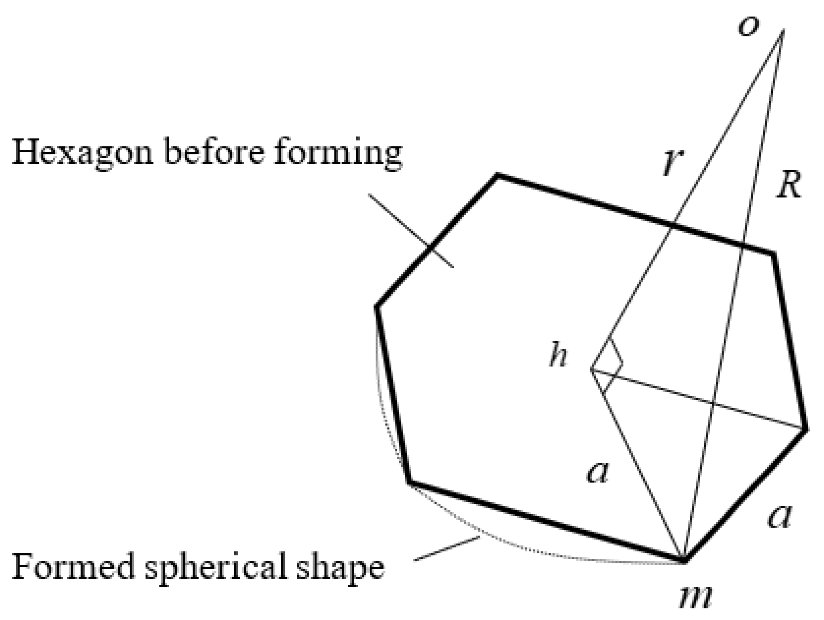
A hexagon was taken from the truncated icosahedron shape in
Figure 2 and is detailed in
Figure 3. The dotted line indicates the molded sphere;
o is the center point of the soccer-ball-shaped preformed box;
h is the center point of the regular hexagon;
m is the vertex of the regular hexagon;
r is the radius of the inscribed sphere of the regular icosahedron, and is expressed by the following equation:
The center point before and after forming does not change, and if the bulge-forming is stopped when the sphere is formed, the distance
R from the center point
o to the vertex
m can be approximated to be equal to the radius of the spherical container. From the relationship between the sides of the right-angled triangle,
ohm, in
Figure 3, the following equation is obtained:
We substitute Equation (1) into Equation (2) to obtain the following:
When designing the forming process, if the radius R of the spherical pressure hull is provided, the parameter, a, of the flat-plate part can be obtained from Equation (3).
To calculate the water pressure required for forming the shape, the spherical pressure hull is cut in half, as shown in
Figure 4, and the following equation is obtained between the internal water pressure,
P, and the side wall stress,
.
Here,
t denotes the wall thickness. During forming, the stress
acting on the sidewall of the spherical pressure hull begins to generate plastic deformation when it reaches the yield stress,
. The required water pressure was calculated using the following equation:
However, because the water pressure at the start of plastic deformation is calculated using Equation (5), the water pressure required for actual processing should be set at 10% to 20% higher.
3. Results
Based on the results of the previous section, a spherical pressure hull was formed using the IHBF method. A spherical container with a radius R = 250 mm was used. The side length, a = 100 mm, adopted for the flat part was obtained using Equation (3). A 1.0-millimeter-thick stainless steel SUS304 plate was used.
Figure 5 details the forming process. First, the regular hexagonal and regular pentagonal flat plate parts were welded to a truncated icosahedron preformed box (
Figure 5a). A bulkhead socket was attached to the center of one hexagonal plate. Next, the hydraulic pressure was applied to the interior of the preformed box, using a manual hydraulic pump (
Figure 5b). The preformed box was transformed into a round sphere using high-pressure water. Finally, the water from the spherical pressure hull was discharged to complete the forming process.
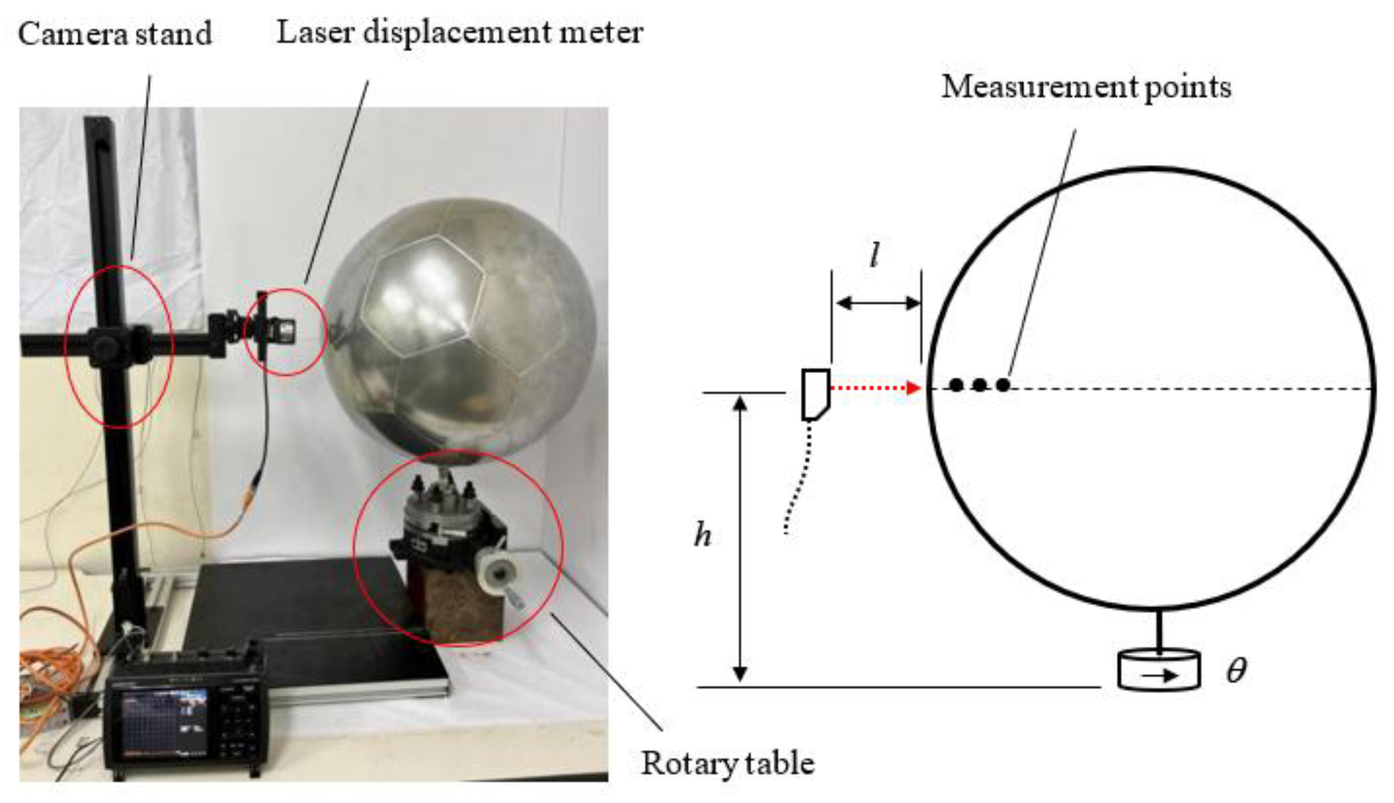
The shape accuracy of the molded spherical pressure hull (
Figure 6) was confirmed by measuring it using a camera stand, rotary table, and laser displacement meter (OPTEX CD22-35VM12, with a measurement accuracy ± 0.01 mm). In
Figure 6, the height
h is measured from the camera stand, the distance
l is measured from the laser displacement meter, the angle
is measured from the rotary table, and coordinate conversion is performed. The three-dimensional coordinate values of the surface of the spherical pressure hull were obtained.
To measure the shape, we adjusted the height of the camera stand, stopped it in the position where the distance read from the laser displacement meter is the largest (corresponding to the diameter of the spherical pressure hull), and record the coordinate values,
h and
l. Then, we rotate the rotary table five degrees at a time, and record the coordinates,
.
Figure 7 shows the results of the measured sample points on the surface of the central section of the spherical pressure hull. The solid blue line indicates the true circle, while the dotted red line indicates the position of the measurement sample points. The maximum distance from the center point to the measurement sample point was 250.50 mm, the minimum distance was 248.14 mm, and the circularity was 2.36 mm. Evidently, the spherical pressure hull had good shape accuracy.
The radius of the spherical pressure hull, formed using flat plate parts with a side length of 100 mm, was 249.32 mm, demonstrating the accuracy of Equation (3). The error for a design radius of 250 mm was −0.27%.
4. Discussion
4.1. Forming Analysis of the Spherical Pressure Hull
The measurement system shown in
Figure 6 cannot obtain detailed data on the stress and wall-thickness distributions of the spherical pressure hull.
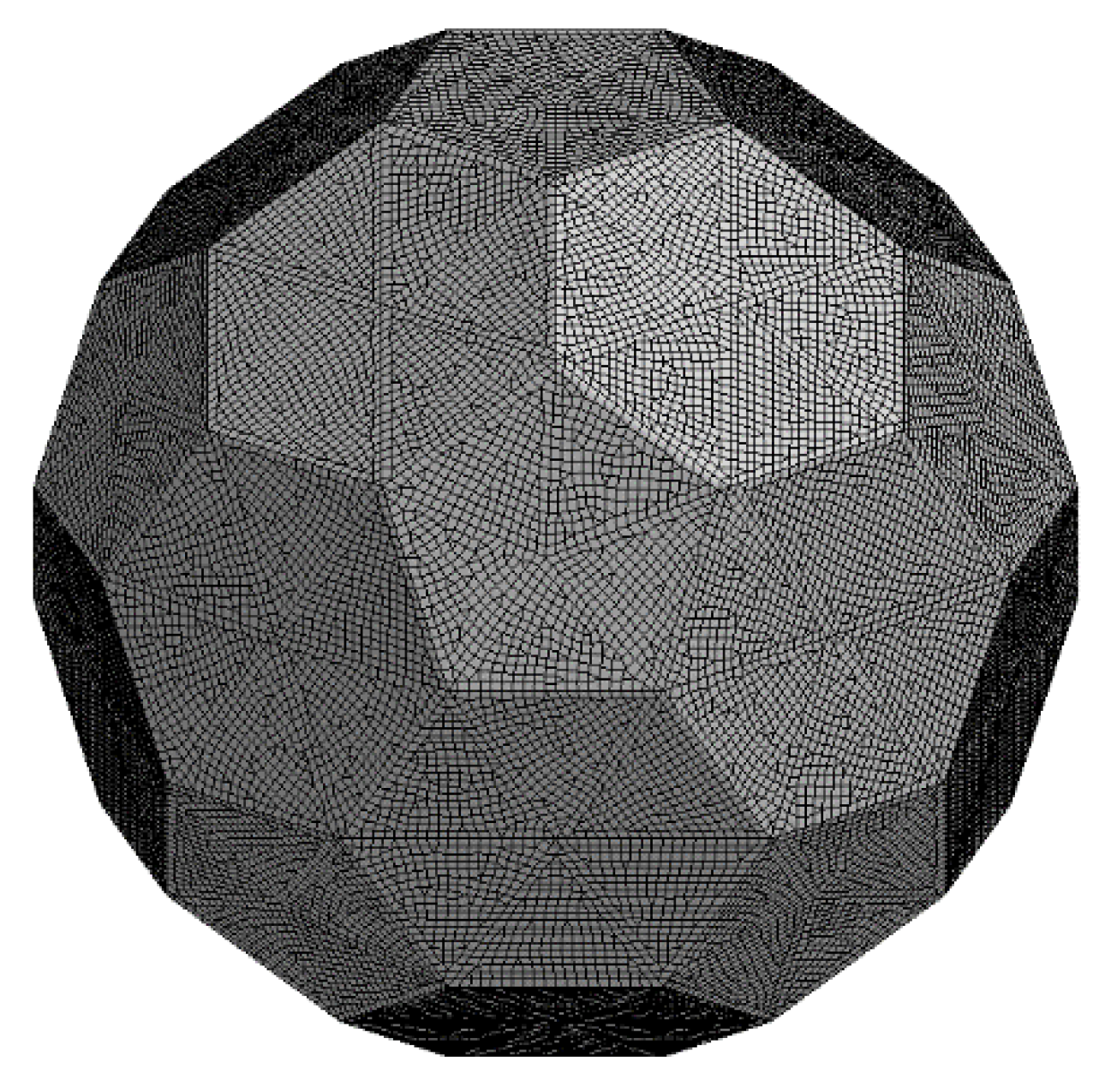
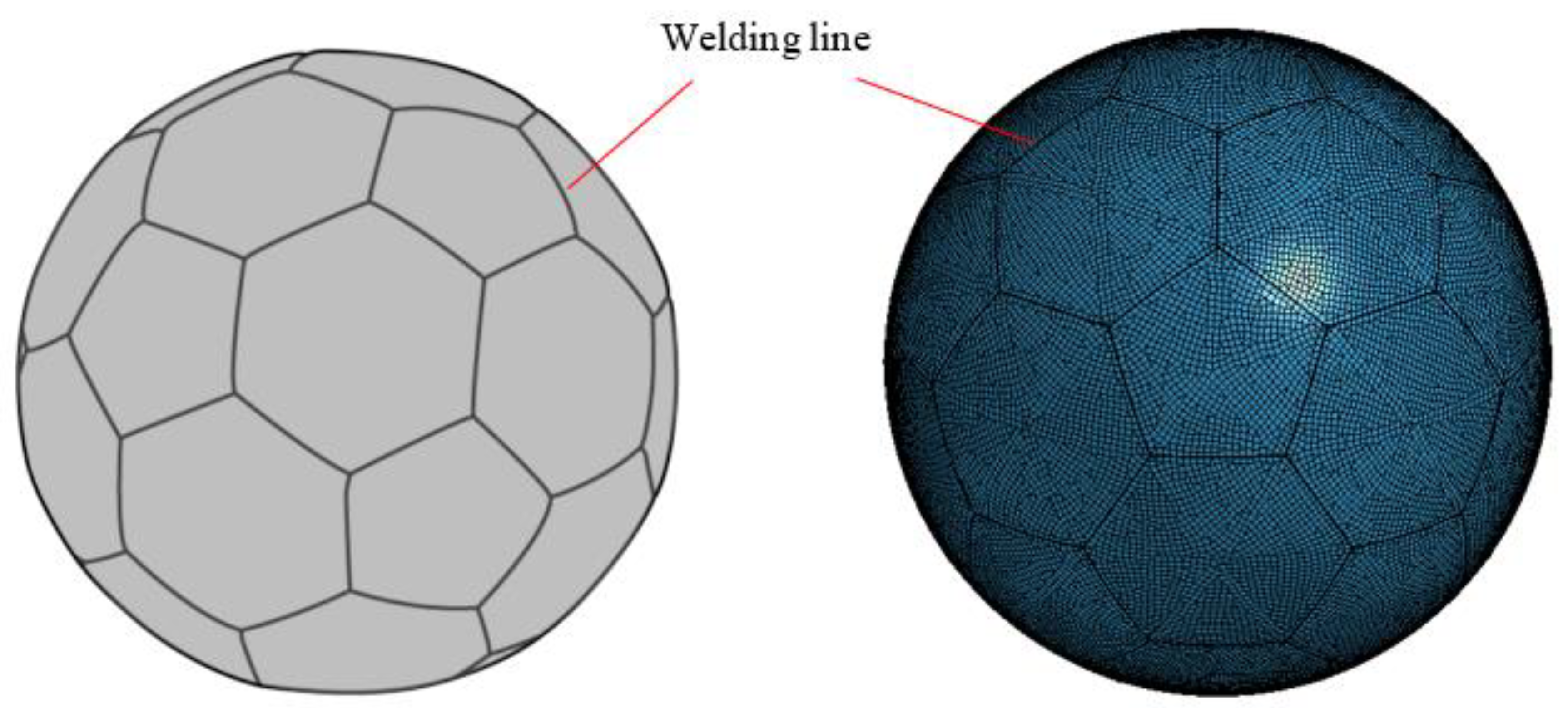
FEM is used to analyze the forming process of a spherical pressure hull. The FEM analysis model (
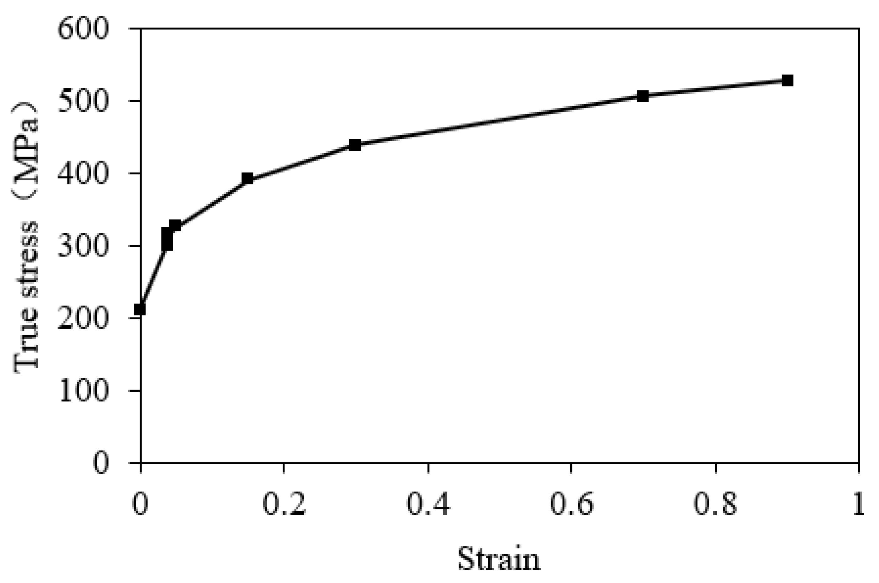
Figure 8) uses quadrilateral and triangular elements with an average side length of 5 mm. The plate thickness was set at 1 mm. Young’s modulus of the stainless steel SUS304 material was 193 GPa, and Poisson’s ratio was 0.3. The stress–strain relationship used for plastic deformation is shown in
Figure 9; the yield stress was 205 MPa. Based on the results of the molding experiments, the maximum internal water pressure for molding was set at 2.0 MPa.
Figure 10 and
Figure 11 show the von Mises stress and wall thickness analysis results, respectively, at the time of formation completion. Because the internal water pressure is completely symmetrical, it can be confirmed that the bulge formation develops uniformly, and a smoothly spherical pressure hull surface is formed.
As shown in
Figure 10, the maximum stress is distributed along the weld line, which may be caused by the bending stress that forms when the folded weld line moves into a spherical surface. The maximum von Mises stress value was 354.7 MPa and the minimum von Mises stress value was 177.2 MPa.
Figure 11 shows that the overall thickness is thinner than a thickness of 1.0 mm before molding. The central part of the regular hexagon is the thinnest, with a thickness of 0.963 mm and a thickness reduction rate of 3.7%. The thickness reduction at the center of the regular pentagon was moderated to a thickness of 0.971 mm and a thickness reduction rate of 2.9%. The thickness reduction was the smallest at the intersection of a regular hexagon and a regular pentagon, with a thickness of 0.997 mm and a thickness reduction rate of 0.3%.
4.2. Effect of Work-Hardening on the Crushing and Buckling Load
Crushing analysis was performed by applying a uniformly distributed load to the formed spherical pressure hull. The FEM analysis model was the same as the shape model formed by the IHBF method, described in
Section 4.1.
The deep-sea pressure is approximated as a uniformly distributed pressure on the deep-sea pressure hull. As shown in
Figure 12, the FEM analysis is performed by gradually increasing the value of the external uniform pressure from zero.
However, it is necessary to consider the work-hardening effect of metal materials in the context of crushing analysis.
For comparison, the analysis model of the same spherical pressure hull is split into two analytical cases: one in which work-hardening is considered and the other in which it is ignored. The analysis results are shown in
Figure 13. The horizontal axis represents the external pressure, and the vertical axis represents the maximum von Mises stress. The red line represents the results of considering work hardening, the black line represents the result of ignoring work hardening, and the blue dotted line represents the results of a simple spherical shell structure.
Figure 13 shows that there is a linear relationship between the pressure and stress at the initial stage of applying the external pressure; however, when the external pressure reaches a certain value, the stress value suddenly increases. This indicates the occurrence of crushing and buckling.
According to
Figure 13, the crushing and buckling load of the spherical pressure shell while ignoring work hardening is 1.35 MPa, which is lower than the crushing and buckling load of 1.65 MPa with the simple spherical shell structure. However, the crushing and buckling load of the formed spherical pressure shell, considering work hardening, was 1.80 MPa, which was approximately 10% higher than that of the simple spherical shell structure.
The main failure mode of deep-sea spherical pressure hulls is plastic buckling, caused by external pressure. To verify the accuracy of the FEM analysis, the FEM solution for the buckling load value of the simple spherical shell is 1.65 MPa, as drawn from
Figure 13. Conversely, the buckling load value of the simple spherical shell can be calculated using Equation (5), the result of which was 1.64 MPa. The error between the FEM solution and the theoretical value was 0.61%. It was, therefore, confirmed that the FEM method used in this study has sufficient analytical accuracy.
Figure 14 shows the crushing deformation mode for each analysis case. From
Figure 14, it can be observed that the crushing and buckling load value has a greater effect on work-hardening; however, the crushing deformation mode has little effect.
4.3. Effect of Local Defects on the Crushing and Buckling Load
Even if there are only minute defects on the surface of the spherical pressure hull under deep-sea pressure, the crushing and buckling load is significantly affected.
As shown in
Figure 15, the thickness of the equivalent-diameter 20 mm area is reduced by half, from 1.0 mm to 0.5 mm. A crushing analysis of a spherical pressure hull, simulating a local defect, was performed.
The following five cases were set up for comparison: (1) a simple spherical shell with no defects; (2) a simple spherical shell with defects; (3) a formed spherical pressure shell without defects; (4) a formed spherical pressure hull with a defect in the center of the pentagon; (5) a formed spherical pressure hull with a defect in the center of the hexagon.
Figure 16 shows the results of the crushing analysis. The solid black line represents the result of a simple spherical shell without defects, and the dotted black line represents the result of a simple spherical shell with defects. The solid red line represents a formed spherical pressure hull without defects, and the dashed red line represents a formed spherical pressure hull with defects.
According to
Figure 16, the crushing and buckling load without defects for the simple spherical shell (case 1) is 1.65 MPa. In the presence of defects (case 2), it is shown that the crushing and buckling load is reduced by 27.8% to 1.20 MPa by concentrating the crushing deformation on the local defects.
In contrast, with the formed spherical pressure hull, the crushing and buckling load of case 3 without local defects was 1.80 MPa. The crushing and buckling load of case 4, with a defect at the center of the regular pentagon, is 1.65 MPa, which is 8.3% smaller than the case study without the defect. The crushing and buckling load of case 5, with a defect in the center of the regular hexagon, is 1.35 MPa, which is 25.0% smaller than in the case without the defect. It was found that the crushing and buckling load of the case with a defect in the center of the regular pentagon was higher than that of the case with a defect in the center of the regular hexagon.
Figure 17 shows the comparison results of the crushing and buckling modes for each analysis. In the absence of local defects, crushing and buckling occurred uniformly on the spherical surface. When a localized defect exists, crush buckling appears to originate from the defect and tends to propagate over time.
Rather than concentrating and bearing external pressure on one localized defect, it would be beneficial to share the overall burden of the spherical structure. Therefore, as shown in
Figure 16, the presence of local defects reduces the crushing and buckling loads.
Even with similar local defects, if a local defect exists on the surface of a simple spherical shell, it is relatively easy to unfold it after crushing and buckling occur. Local defects on the surface of the formed spherical pressure hull tend to be relatively difficult to develop. In addition, the crushing and buckling load when the local defect is in the center of the regular pentagon is higher than that when the local defect is in the center of the regular hexagon. It was found to be beneficial to design the shape to be relatively difficult to unfold as much as possible after crushing and buckling occur.
4.4. The Effect of the Weld Line Size on the Crushing and Buckling Load
Examining the effect of the size of the weld lines on the crushing and buckling load of the spherical pressure hull is required because weld lines are always left in spherical pressure hulls formed using the IHBF method. The crush analysis model in
Figure 18 shows the effect of the weld line.
One-dimensional beam elements were added along the fold lines of the preformed box for the purposes of analysis. The beam elements and fold lines are connected via common nodes. The beam elements and preformed boxes have the same material properties. The size of the beam element (the diameter of the circular section) that was added along the weld line is divided into four cases for analysis: 2.0, 3.0, 4.0, and 5.0 mm. The results of each crushing analysis are shown in
Figure 19.
It can be observed from
Figure 19 that the crushing and buckling load remained unchanged at 1.80 MPa, even when the size of the weld line was changed. Therefore, the uniform distribution of the weld lines dominated the crushing and buckling mode, indicating that the size of the weld line had little effect on the crushing and buckling load.
Figure 20 shows the crushing deformation mode for each spherical pressure hull, with the different weld lines. The weld line size has little effect on the crushing deformation mode, as observed in
Figure 20.
5. Conclusions
In this study, a new type of spherical pressure hull formed using the IHBF method is proposed to address the design and manufacturing problems of spherical pressure hulls for deep-sea submarines. The crushing and buckling performance of the spherical pressure hull under an external water pressure load was investigated, and the following conclusions were drawn:
(1) The calculation formula for the flat-plate component dimensions and that for the necessary water pressure for forming the shape were derived to design the spherical pressure hull. We conducted a molding experiment on a spherical container and confirmed the accuracy of the formulas used for the calculations.
(2) A design target of a 250-millimeter radius was used for the IHBF-forming experiments. The actual radius of the spherical pressure hull obtained by IHBF using the flat-plate components was 249.32 mm. The error from the design target radius was 0.27%. The surface of the spherical pressure hull was smooth, with a circularity of 2.36 mm. FEM analysis of the forming process showed that the maximum von Mises stress was 354.7 MPa, and the maximum thickness reduction rate was 3.7%. Therefore, the ability of the IHFB to produce a stable and high-quality spherical pressure hull was confirmed.
(3) The FEM crushing analysis was performed by applying external water pressure to a spherical pressure hull formed via IHBF. The results indicate that owing to the work-hardening of the spherical pressure shell, it was approximately 10% larger than that of the conventional simple spherical shell structure.
(4) The effects of local defects and the weld line size on the crushing and buckling performance of spherical pressure hulls were investigated using FEM analysis. The crushing and buckling load of a spherical pressure hull under a symmetrical and uniform pressure was significantly affected by local defects. It was observed that the weld line size had a relatively small effect on the crushing and buckling load of the spherical pressure hull.
In future studies, we aim to develop a pressure hull that can be used for actual deep-sea submarines. We will conduct detailed studies on issues such as the development of large or laminated spherical pressure hulls.


