Article

Trihedral Lattice Towers Optimization with a Limitation on the Resonant Vortex Excitation Occurrence

1
Strength of Materials Department, Faculty of Civil and Industrial Engineering, Don State Technical University, 344002 Rostov-on-Don, Russia
2
Engineering Geology, Bases and Foundations Department, Faculty of Civil and Industrial Engineering, Don State Technical University, 344002 Rostov-on-Don, Russia
*
Author to whom correspondence should be addressed.
Designs 2023, 7(1), 10; https://doi.org/10.3390/designs7010010
Submission received: 2 December 2022 / Revised: 3 January 2023 / Accepted: 6 January 2023 / Published: 9 January 2023
(This article belongs to the Section Civil Engineering Design)

Abstract

:
Trihedral lattice towers are widely used as transmission line supports, wind turbine supports, cell towers, and floodlight towers. The aim of this work is to develop a technique for optimizing trihedral lattice supports to reduce their weight, taking into account the limitation on resonant vortex excitation. At the same time, restrictions are also introduced on the maximum stress, as well as the ultimate slenderness of the elements. Thus, with a minimum weight, the tower must meet all the requirements of the design codes. A lattice tower used as a floodlight mast is considered. The tower consists of two sections, the upper of which is of constant width, and the width of the lower section varies according to a linear law. The elements of the tower are made from pipes with an annular cross section. The sections’ widths and heights, the dimensions of elements’ cross-sections, and the number of panels are the variable parameters. The solution of the nonlinear optimization problem is implemented in MATLAB software. Internal forces in the tower and natural frequencies are calculated by the finite element method. The tower is subjected to the action of ice and wind loads, dead weight and the weight of the equipment. The wind load is considered as the sum of the average and pulsation components. To solve the problem of nonlinear optimization, the surrogate optimization method and the genetic algorithm are used. One of the serially used designs was chosen as the initial approximation. The design obtained as a result of optimization compared to the initial approximation has a mass more than two times less and at the same time satisfies all design requirements.

1. Introduction

Lattice tower structures are widely used in the practice of erecting steel supports for power lines [1,2,3,4,5], wind turbine towers [6,7,8,9,10], and towers for placing lighting equipment [11]. At the same time, supports with a trihedral cross section are more economical than tetrahedral ones [12,13,14,15]. It is shown in ref. [16,17,18] that the economic efficiency of tower structures essentially depends on their geometry, as well as the shape and size of the elements’ cross-section.
There is a significant amount of literature on methods for optimizing steel lattice towers. In [19], the optimization of the tower geometry was performed by combining the genetic algorithm and the object-oriented approach. The tower was considered as a set of small objects. With an object-oriented approach, tower panels are optimized independently. The objective function is the weight of the tower. The magnitude of the stress and the critical load at which buckling occurs are the main limitations.
Paper [20] presents a method that combines differential evolution, a powerful optimization algorithm, and a machine learning-based classification model to minimize the weight of lattice structures. The authors have developed a classification model based on the Adaptive Boosting algorithm, which screens out unpromising options during the optimization process.
The optimization of the wind turbine tower structure with a lattice-tubular hybrid design was performed in [21] using the particle swarm method. The objective function is the weight, which should be minimal. Limitations are the magnitude of the stress, the slenderness of the elements and the first natural frequency.
Four non-linear optimization methods were used in [22] to optimize steel lattice structures: the interior point method, the surrogate optimization method, the genetic algorithm, and the pattern search method. The determination of forces in the tower was carried out by the finite element method. The efficiency of the above optimization methods was compared. The potential energy of deformation, displacement of the top of the tower and the first natural frequency acted as the target function.
The optimization of such geometrical parameters of the tower as the angle of inclination of the lattice and tower width is carried out in [23]. At the same time, the width of the tower remains constant in height, but it is advisable to decrease it towards the top. The article [24] searches for the optimal cross section shape of the chords for a trihedral lattice tower, but does not address the issues of optimizing the geometry of the tower overall.
The author of [25] proposes an adaptive differential evolution algorithm for optimizing bar systems. The proposed algorithm is tested on the example of dome truss structures. The mass of the structure acts as an optimization criterion. Restrictions on natural frequencies are introduced.
The author of [26] considers the enhanced shuffled shepherd optimization algorithm for optimizing spherical truss domes according to the criterion of minimum mass with restrictions on stresses in the elements. The authors of papers [27,28] are also devoted to topology optimization of such lightweight bar systems as domes.
Of particular interest are the results of lattice towers full-scale experimental studies, which are given in papers [29,30].
For the lattice towers, in addition to calculating the strength, rigidity and stability of the structure, it is necessary to check for the absence of resonant vortex excitation [31]. This limitation was not considered in the above publications.
The purpose of this work is to develop a methodology for optimizing trihedral lattice supports according to the criterion of minimum mass, taking into account the limitations on the strength, rigidity and stability of the elements, as well as the absence of resonant vortex excitation. Our solution will be based on the Russian design codes SR 20.13330.2016 “Loads and impacts” and SR 16.13330.2017 “Steel structures”. The problem of lattice structures optimization, taking into account the restriction on resonant vortex excitation occurrence, is solved in this article for the first time.

2. Materials and Methods

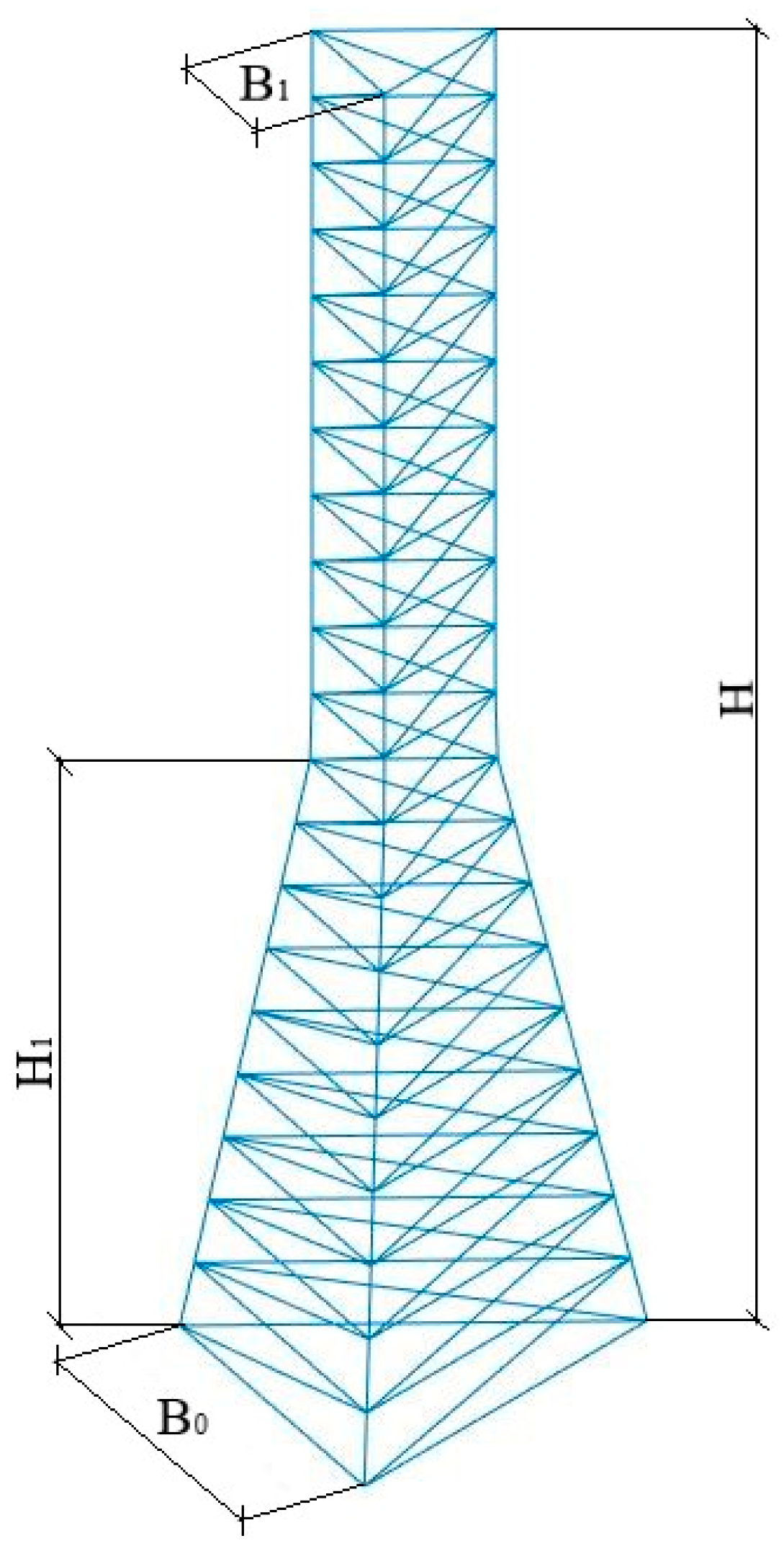
2.1. Formulation of the Problem

A trihedral lattice tower used as a projector mast is considered. The material of the tower elements is assumed to be linear and isotropic. The tower consists of two sections (Figure 1). The width of the lower section varies from B0 to B1 depending on the z coordinate according to a linear law. The height of the lower section is H1. The total height of the tower H is constant. The number of panels in the lower section is n1. The width of the upper section is constant and equal to B1. The number of panels in the upper section is n2. The cross sections of the chords and the lattice are round pipes. The outer cross-section diameter of the lower section chords is Dp. For the upper section, it is equal to Dp1. The outer diameter of the braces of the lower section is Dr. For the upper section, it is equal to Dr1. The outer diameter of the lower section horizontal elements is Dh. For the upper section, it is equal Dh1. The lower nodes are fixed from linear displacements along x, y, z axes.
The stiffness and stability of the tower elements is mainly affected by the cross sections moments of inertia. In the case of round pipes, the axial moment of inertia takes on a maximum value at the maximum outer diameter and minimum wall thickness. In assortments of round pipes, the outer diameter does not change continuously, but discretely, which makes it impossible to use gradient methods when solving the optimization problem. To be able to use them, we will assume that the outer diameter of the pipe is a continuous value. The minimum wall thickness t of round pipes depends on the outer diameter. The graph of this dependence, drawn according to the Russian standard GOST 8732-78, is shown in Figure 2. This graph is well approximated by the linear function, the equation of which is also shown in Figure 2.
The variable parameters are B0, B1, H1, Dp, Dp1, Dr, Dr1, Dh, Dh1, n1, n2. Tower height H is constant.
The loads acting on the tower include the dead weight of the structure and technological equipment placed on it, in addition to ice and wind.
Ice load is determined in accordance with Russian design codes SR 20.13330.2016.
The normative value of the linear ice load with an outer diameter D of sections up to 70 mm is determined by the formula:
i = π b k μ 1 D + b k μ 1 ρ i c e g
For structural elements with an outer diameter of more than 70 mm, the normative value of the surface ice load i , Pa is determined by the formula:
i = b k μ 2 ρ i c e g .
In Formulas (1) and (2), b is the normative value of the ice wall thickness (exceeded on average once every 5 years), on elements of a circular section with a diameter of 10 mm, located at a height of 10 m, taken according to Table 12.1 of SR 20.13330.2016;
  • k is the coefficient taking into account the change in the thickness of the ice along the height. It is adopted according to Table 12.3 of SR 20.13330.2016;
  • μ 1 is the coefficient that takes into account the change in the thickness of the ice depending on the diameter of the elements of the circular cross-section. It is determined according to Table 12.4 of SR 20.13330.2016;
  • μ 2 is the coefficient that takes into account the ratio of the surface area of the element subject to icing to the total surface area of the element. μ 2 is taken equal to 0.6;
  • ρ i c e is the ice density taken equal to 900 kg/m3;
  • g is the acceleration of gravity, m/s2.
For tower structures, the wind load is the main variable in the calculation of strength and deformability and is determined as the sum of the average and pulsation components. The components of the wind load were also determined according to SR 20.13330.2016.
The normative value of the wind load average component w m depending on the height z above the ground is determined by the formula:
w m = w 0 k z c ,
where w 0 is the normative value of wind pressure, determined according to Table 11.1. SR 20.13330.2016, k(z) is a coefficient that takes into account the change in wind pressure along the height determined from Table 11.2 SR 20.13330.2016, c is the aerodynamic coefficient.
The standard value of the pulsation component w p is determined as follows:
(1)
for structures in which the first natural frequency f 1 , Hz, is greater than the limit value of natural frequency f l i m (according to Table 11.5 of SR 20.13330.2016):
w p = w m ζ z ν ,
where ζ z is the wind pressure pulsation coefficient, taken according to Table 11.4 SR 20.13330.2016;
ν is the spatial correlation coefficient of wind pressure pulsations.
(2)
for structures with f 1 < f l i m < f 2 :
w p = w m ξ ζ z ν ,
where f 2 is the second natural frequency, ξ is the dynamism coefficient, determined from Figure 11.1 of SR 20.13330.2016 depending on the logarithmic oscillation decrement δ and the parameter ε 1 , which is determined by the formula:
ε 1 = w 0 k z γ f 940   f 1 ,
where γ f = 1.4 wind load safety factor.
(3)
For structures, in which the second natural frequency is less than the limiting one, the dynamic calculation is made taking into account the s first vibration modes. The number s is determined from the condition f s < f l i m < f s + 1 .
The mass of the elements of the structure is reduced to nodes.
The inertial force applied to the node with the number j in the direction of the degree of freedom p when the structure vibrates according to the i-th eigenmode is determined by the formula:
Q i j p = M j ξ i η i j p ,
where M j is the mass at the j-th node, ξ i is the dynamism coefficient determined from Figure 11.1 SR 20.13330.2016 depending on the logarithmic oscillation decrement δ and the parameter ε i = w 0 k z γ f 940   f i , η i j p is the reduced acceleration of the j-th node in the direction of the p-th degree of freedom
η i j p = y i j p k = 1 r l = 1 q Q k l m ζ z y i k l k = 1 r l = 1 q y i k l 2 M k ,
where y i j p is the displacement of the j-th node during vibrations along the i-th eigenmode in the direction of the p-th degree of freedom;
  • r is the total number of nodes;
  • q is the number of degrees of freedom in the node;
  • Q k l m is the nodal load from the average component of the wind pressure in the node k in the direction of the l-th degree of freedom.
The resulting forces and displacements T r e s , taking into account the dynamic response to s eigenmodes, are determined by the formula:
T r e s = T m + T 1 2 + T 2 2 + T s 2 ,
where T m is the force (displacement) from the average component of the wind pressure.
The objective function is the mass of the structure, which should reach a minimum. The mass of the structure is calculated as the sum of the masses of the bar elements without taking into account the connecting parts (gussets, etc.):
M = ρ i = 1 n A i l i m i n ,
where A i and l i are the cross-sectional area and length of the i-th element, respectively, and ρ is the steel density.
The following restrictions must be satisfied:
1.
Structural elements must satisfy the conditions of strength N A R y γ c and stability N φ · A R y γ c , where N is the axial force in the element, A is the cross-sectional area of the element, φ is the coefficient of buckling, γc is the coefficient of working conditions, Ry is the design strength of steel.
The buckling coefficient in accordance with SR 16.13330.2017 is calculated by the formula:
φ = 0.5 δ δ 2 39.48 λ ¯ 2 λ ¯ 2 ,
where λ ¯ = λ R y / E is the reduced slenderness of the element, E is the modulus of elasticity of steel, λ = l 0 / i m i n is the slenderness of the element, i m i n is the cross section minimum radius of gyration, l 0 is the design length of the element, δ = 9.87 1 0.03 + 0.06 λ ¯ + λ ¯ 2 .
For simplification, the design length of all elements was taken equal to their actual length l.
When assessing the strength and stability of the elements, the design combination of loads is taken as the design value of N:
N = N g + ψ t 1 N w + ψ t 2 N i c e ,
where N g is the design axial force in the element from its dead weight and the weight of the equipment, N w is the design axial force from the effect of wind, N i c e is the design axial force from the ice load, ψ t 1 = 1 and ψ t 2 = 0.9 are the combination coefficients.
When specifying loads, the dead weight is taken with a safety factor of 1.05, wind load is taken with a safety factor of 1.4, and ice load is taken with a safety factor of 1.8.
2.
The slenderness of the elements should not exceed the limit values λ < λ u . Ultimate slenderness is determined in accordance with SR 16.13330.2017. For compressed chord elements:
λ u = 180 60 α ,
where α = N / φ A R y γ c .
For compressed lattice elements:
λ u = 210 60 α .
The parameter α in Formulas (13) and (14) is assumed to be at least 0.5.
For tensioned elements of the chords, the ultimate slenderness is assumed to be 250, and for tensioned elements of the lattice it is equal to 350.
3.
Resonant vortex excitation should not occur in the structure. In accordance with SR 20.13330.2016, resonant vortex excitation in the i-th eigenmode does not occur if
V c r , i > V m a x z e q v ,  
where V m a x z e q is the maximum wind speed at the level z e q , determined by the formula:
V m a x z e q = 1.5 w 0 k z e q .
The coefficient k, as in Formula (3), takes into account the change in wind pressure with height, and is determined from Table 11.2 SR 20.13330.2016. For tower structures z e q = 0.8   H .
Critical wind speed, at which resonant vortex excitation occurs according to the i-th eigenmode, is determined by the formula:
V c r , i = k ν f i d S t ,
where f i is the natural frequency in the i-th bending eigenmode, d is the transverse dimension of the structure, and S t = 0.11 is the Strouhal number of the tower cross section.
The Russian standards recommend taking the value of the k ν coefficient in the range from 0.9 to 1.1. The most unfavorable variant takes place at k ν = 0.9, so this value was taken by the authors for calculation.
The transverse size of the structure was calculated as its average width according to the formula:
d = B 0 + B 1 2 H 1 H + B 1 H H 1 H .
4.
Variable parameters x i must lie in the range ( l b x i   u b )
5.
Parameters n 1 and n 2 must be integers.

2.2. Technique for Solving the Optimization Problem

The solution of the lattice tower optimization problem was implemented in the MATLAB environment. The limitations presented in Section 2.1 require the calculation of the internal forces and natural frequencies of the tower, which was implemented using the finite element method (FEM).
To model a trihedral lattice tower, spatial bar finite elements (FE) (Figure 3) with three degrees of freedom at the node (linear displacements u, v, w along the x, y, z axes) were used.
The local stiffness matrix of an element working only in tension or compression has the form:
K e = E A l 1 1 1 1 ,
where E is the modulus of elasticity of the material, A is the cross-sectional area of the element, and l is the length of the FE.
The transition from the local coordinate system to the global one is carried out according to the formulas:
K = L T K e L ;   U e = L U ,
where U e = u ¯ 1   u ¯ 2 T and U = u 1   v 1   w 1   u 2   v 2   w 2 T are the displacement vectors in the local and global coordinate systems, respectively, K is the stiffness matrix in the global coordinate system, and the matrix L has the form:
L = λ x x λ x y λ x z 0 0 0 0 0 0 λ x x λ x y λ x z ,
where λ i j are the direction cosines between the i and j axes.
The direction cosines included in Formula (21) are defined as follows:
λ x x = x 2 x 1 l ;   λ x y = y 2 y 1 l ;   λ x z = z 2 z 1 l ,
where x 1 ,   x 2 ,   y 1 ,   y 2 ,   z 1 ,   z 2 are the coordinates of the bar ends.
Displacements are determined from the solution of the FEM system of equations, which has the well-known form
K U = F ,
where F is the vector of nodal loads.
The forces in the bars are determined by the formula:
N = E A l u 2 u 1 ,
where u 2 and u 1 are the displacements of the bar ends along its axis.
Natural vibration frequencies f i are determined from the equation:
det K ω 2 M = 0 ,
where det (…) is the matrix determinant, M is the diagonal mass matrix, ω i = 2 π f i .
All the necessary tables and graphs of the coefficients from SR 20.13330.2016 were included in the program, and linear interpolation was performed for intermediate values.
The problem statement described in Section 2.1 contains nonlinear inequality constraints and integer constraints. Very few optimization methods allow taking into account such limitations. The optimization problem was solved by the surrogate optimization method and the genetic algorithm in MATLAB.
The essence of the surrogate optimization is to find a global minimum of an objective function using few objective function evaluations. To do so, the algorithm replaces the objective function with its approximation (surrogate), which takes little time to evaluate [32].
The surrogate is created as an interpolation of the objective function by a radial basis function in randomly generated points [33].
The genetic algorithm is a method for solving nonlinear optimization problems with complex constraints. This method is based on a natural selection process. At each iteration, a set of points is generated and repeatedly modified, mimicking biological evolution [34].

3. Results

A steel tower with a total height H = 23 m was considered. The material characteristics were E = 206 GPa, R y = 235 MPa, γ c = 1. The normative value of wind pressure was w 0 = 0.38 kPa, and ice wall thickness was b = 10 mm. These parameters correspond to the climatic conditions of Rostov-on-Don, Russia. Type A was chosen as the type of terrain from SR 20.13330.2016 (open areas with buildings less than 10 m high). The limiting vibration frequency for the considered wind region is f l i m = 3.8 Hz. The weight of the equipment at the top of the tower was 5 kN. It was applied in the form of three identical concentrated forces at the top nodes. In addition to the weight of the equipment, a load of 1 kN was applied to one of the upper nodes, simulating the weight of a person. In the initial approximation, the following values of the geometric parameters of the tower were taken: width B0 = 2.14 m, B1 = 1.84 m, and height of the lower section H1 = 10.5 m. Chords were made of round pipes with a section D × t 170 × 2.8 mm, braces had a section 65 × 3 mm, and horizontal elements had a section of 53 × 3 mm. These parameters correspond to one of the serially used tower structures. The mass of the tower in the initial approximation was 2 tons.
As the calculation showed, this tower meets the requirements for strength, rigidity, and stability, but does not satisfy the test for the absence of resonant vortex excitation for the assumed climatic conditions.
The upper (ub) and lower (lb) limits for the variable parameters are given in Table 1. The upper bound for the parameter B0 is usually limited by the area of the site where the structure is located, and the equipment located in the upper part of the tower limits the lower bound for the parameter B1. The existing product range of the pipe manufacturers usually limits the cross-sectional diameters.
Figure 4 shows a graph of the optimization process progress when using the surrogate optimization method. In this method, there is no explicit criterion for the completion of the optimization process, and we stopped the calculation after 7500 iterations.
The optimal shape of the tower obtained as a result of solving the problem by the surrogate optimization method is shown in Figure 5.
The mass of the tower is 891 kg. The outer diameters of the chords’ cross-section were 83.5 mm and 43.2 mm. The diameters of the inclined elements of the lattice were 68.1 mm and 34.3 mm. The diameters of the horizontal elements of the lattice were 52 mm and 26.7 mm. Corresponding wall thicknesses calculated by Formula (4) are 3.4 and 2.7 mm for chords, 3.1 and 2.5 mm for braces, and 2.8 and 2.5 mm for the horizontal elements. The obtained optimal values of the remaining variable parameters are given in Table 2.
The sections of the elements were rounded to the nearest values according to the GOST 8732-78* assortment. The final sections are given in Table 3.
Furthermore, the tower was exported to the LIRA-SAPR software package for testing [35]. In this software package, the tower chords were modeled by finite elements with six degrees of freedom per node (three translational and three rotational degrees), and the lattice elements were modeled by finite elements with three translational degrees of freedom per node.
The results of checking the assigned sections for strength, stability and slenderness are shown in Figure 6 and Figure 7. The maximum value of the ratio N N u   100 % , where N u is the ultimate force, is 26.9%, and the maximum ratio λ λ u 100 % is 99.7%.
The first vibration frequency in LIRA-SAPR was 1.96 Hz, which differs from the solution in the program developed by the authors by 0.5%. The critical wind speed at which the resonant vortex excitation of this tower occurs according to the first eigenmode is 32.2 m/s, which is higher than the value V m a x   z e q = 32.04 m/s.
The progress of the optimization process when using the genetic algorithm is shown in Figure 8. The optimization process was completed after 270 generations, and the total number of the objective function evaluations was 25,755. The shape of the tower obtained using the genetic algorithm is shown in Figure 9.
The mass of the tower shown in Figure 9 was 834.5 kg. The diameters of the pipes of the chords were 75.2 mm and 46.8 mm. The diameters of the inclined lattice elements were 65.9 mm and 50.8 mm. The horizontal elements of the lattice had diameters of 51.6 mm and 31.5 mm. Corresponding wall thicknesses calculated by Formula (4) were 3.2 and 2.7 mm for chords, 3.1 and 2.8 mm for braces, and 2.8 and 2.5 mm for horizontal elements. The obtained optimal values of the remaining variable parameters are given in Table 4.
The final cross-sections of the elements, adopted in accordance with the assortment of GOST 8732-78*, are given in Table 5.
The resulting solution was also exported to the LIRA-SAPR software package. The results of checking the elements for strength and slenderness are shown in Figure 10 and Figure 11. The maximum value of the ratio N N u   100 % was 59.9%. The slenderness of all elements with the exception of one element of the chord in the upper part of the tower was below the limit. For one element, the excess of slenderness relative to the ultimate slenderness was 2%. This can be explained, firstly, by the rounding of diameters and wall thicknesses, and, secondly, by the difference in finite element models in LIRA-SAPR and MATLAB. When optimizing, the rotational degrees of freedom for the finite elements of the chords were not taken into account.
The first vibration frequency for the adopted design solution was 1.76 Hz when calculating in LIRA-SAPR. The critical wind speed at which the resonant vortex excitation of this tower occurs according to the first natural mode of vibration was V c r = 31 m/s, which is 3.2% lower, than V m a x z e q . The downward deviation of the critical wind speed can also be explained by the rounding of the cross sections dimensions and the difference between the finite elements used in LIRA-SAPR and MATLAB.

4. Discussion

The results obtained show a rather high efficiency of the surrogate optimization method and the genetic algorithm in the solution of the formulated problem. In both cases, the mass of the structure was reduced by a factor of more than two. The genetic algorithm in this problem turned out to be more efficient than the surrogate optimization method. In addition to the smaller mass of the structure, the solution based on the genetic algorithm contains a smaller number of nodes, which also helps to reduce the complexity of building the tower and its cost [36]. Note that in [22], the surrogate optimization method and the genetic algorithm were compared earlier, and the opposite result was obtained: the genetic algorithm proved to be much worse than the surrogate optimization algorithm. However, the formulation of the problem in [22] differed significantly: the mass of the structure acted not as an objective function, but as a constraint, and there was only one non-linear constraint. Furthermore, in [22] the high efficiency of the interior point method was noted. The specified method does not allow for the setting of integer constraints. For the problem considered in this article, an attempt was made to apply this method for fixed n1 and n2. However, the use of the interior point method leads to convergence to an infeasible point, which can be explained by a large number of nonlinear constraints. In addition, the interior point method finds the local minimum of the function, but not the global one. Figure 4 shows that the objective function contains many local minima, so the algorithm has to periodically reset and re-generate the starting point of the search. The Lagrange multiplier method is also inapplicable for this class of problems [37].
As a result of optimization, there is a noticeable increase in the width of the tower B0 compared to the initial approximation (by almost 1 m), which can be explained by an increase in the overall rigidity of the structure. At the same time, the optimum is not achieved at the maximum possible width, which was assumed to be 5 m. Note that in [22], when optimizing according to the criterion of minimum potential strain energy and minimum displacement, the optimum was achieved at the maximum possible width, B0. However, there was no restriction on the slenderness of the elements in that work.
The presented results also show that the main limiting factors in the search for the optimal design solution for the considered tower are the slenderness of the elements and the absence of resonant vortex excitation. For the solution obtained by the surrogate optimization method, the degree of loading of the elements is noticeably lower than 50%, and for the solution based on the genetic algorithm, it exceeds 50% only in individual elements. This makes it possible to exclude the criterion of strength and stability of elements from the restrictions when searching for the optimal geometry of the tower. Instead, when determining the ultimate flexibility, one can put α = 0.6 for the compressed elements of the chords and α = 0.5 for the remaining compressed elements. The limiting slenderness for them will then be 144 and 180, respectively. Reducing the number of constraints can significantly increase the speed of solving the optimization problem.
It is also possible to choose the ratio of the first natural frequency of the structure to the mass f 1 / M as the objective function, as is done, for example, in [38], but at the same time introduce a restriction on the slenderness of the elements. This will increase the first frequency while keeping the weight of the structure as low as possible. An increase in the first frequency will lead to an increase in the resistance of the structure to resonant vortex excitation. Our further investigations will be aimed at solving the problem in this formulation. In addition, our further research will be devoted to experiments on lattice towers’ small-scale models.

5. Conclusions

1. A technique has been developed for optimizing trihedral lattice towers according to the criterion of minimum mass, taking into account the restriction on the occurrence of resonant vortex excitation based on the surrogate optimization method and the genetic algorithm. In comparison with the initial approximation, the mass of the structure was reduced by more than a factor of two as a result of optimization.
2. A comparison of the surrogate optimization method and the genetic algorithm was made, which showed a higher efficiency of the latter with a large number of nonlinear constraints.
3. It has been established that the main factors limiting the constructive solution of the tower are the ultimate slenderness of the elements and the limitation on the resonant vortex excitation occurrence. The degree of loading of the elements in the optimal solution does not exceed 60%. Thus, as a simplification in the first approximation, it is possible to remove the restrictions on the magnitude of the stress in the elements.

Author Contributions

Conceptualization, A.C. and L.A.; methodology, A.C., V.A. and L.A.; software, A.C.; validation, I.I., V.A. and L.A.; formal analysis, V.A.; investigation, L.A.; resources, V.A.; data curation, A.C.; writing—original draft preparation, A.C.; writing—review and editing, I.I.; visualization, I.I.; supervision, A.C.; project administration, A.C.; funding acquisition, V.A. All authors have read and agreed to the published version of the manuscript.

Funding

The APC was funded by Don State Technical University.

Institutional Review Board Statement

Not applicable.

Informed Consent Statement

Not applicable.

Data Availability Statement

Not applicable.

Acknowledgments

The authors would like to acknowledge the administration of Don State Technical University for their resources and financial support.

Conflicts of Interest

The authors declare that they have no conflict of interest. The funders had no role in the design of the study; in the collection, analyses, or interpretation of data; in the writing of the manuscript; or in the decision to publish the results.

References

  1. Shu, Q.; Huang, Z.; Yuan, G.; Ma, W.; Ye, S.; Zhou, J. Impact of wind loads on the resistance capacity of the transmission tower subjected to ground surface deformations. Thin-Walled Struct. 2018, 131, 619–630. [Google Scholar] [CrossRef]
  2. Yuan, G.; Yang, B.; Huang, Z.; Tan, X. Experimental study on the stability of the transmission tower with hybrid slab foundation. Eng. Struct. 2018, 162, 151–165. [Google Scholar] [CrossRef] [Green Version]
  3. Xie, Q.; Zhang, J. Experimental study on failure modes and retrofitting method of latticed transmission tower. Eng. Struct. 2021, 226, 111365. [Google Scholar] [CrossRef]
  4. Tian, L.; Pan, H.; Ma, R.; Zhang, L.; Liu, Z. Full-scale test and numerical failure analysis of a latticed steel tubular transmission tower. Eng. Struct. 2020, 208, 109919. [Google Scholar] [CrossRef]
  5. Singh, V.K.; Gautam, A.K. Study on Evaluation of Angle Connection for Transmission Towers. In International Conference on Advances in Structural Mechanics and Applications; Springer: Cham, Switzerland, 2022; pp. 353–363. [Google Scholar] [CrossRef]
  6. Axisa, R.; Muscat, M.; Sant, T.; Farrugia, R.N. Structural assessment of a lattice tower for a small, multi-bladed wind turbine. Int. J. Energy Environ. Eng. 2017, 8, 343–358. [Google Scholar] [CrossRef] [Green Version]
  7. Zwick, D.; Muskulus, M.; Moe, G. Iterative optimization approach for the design of full-height lattice towers for offshore wind turbines. Energy Procedia 2012, 24, 297–304. [Google Scholar] [CrossRef] [Green Version]
  8. Chew, K.H.; Tai, K.; Ng, E.Y.K.; Muskulus, M. Optimization of offshore wind turbine support structures using an analytical gradient-based method. Energy Procedia 2015, 80, 100–107. [Google Scholar] [CrossRef] [Green Version]
  9. Das, A. Modelling and analysis of lattice towers for wind turbines. Int. J. Sci. Res. 2015, 4, 999–1003. [Google Scholar]
  10. Stavridou, N.; Koltsakis, E.; Baniotopoulos, C. Structural analysis and optimal design of steel lattice wind turbine towers. Proc. Inst. Civ. Eng. -Struct. Build. 2019, 172, 564–579. [Google Scholar] [CrossRef]
  11. Balagopal, R.; Prasad Rao, N.; Rokade, R.P. Simplified model to predict deflection and natural frequency of steel pole structures. J. Inst. Eng. (India) Ser. A. 2018, 99, 595–607. [Google Scholar] [CrossRef]
  12. Zhou, Q.; Zhao, L.; Zhu, Q.; Zhu, Y. Mean wind loads on equilateral triangular lattice tower under skewed wind loading. J. Wind Eng. Ind. Aerodyn. 2021, 208, 104467. [Google Scholar] [CrossRef]
  13. Ghugal, Y.M.; Salunkhe, U.S. Analysis and Design of three and four legged 400kV steel transmission line towers: Comparative study. Int. J. Earth Sci. Eng. 2011, 4, 691–694. [Google Scholar]
  14. Preeti, C.; Mohan, K.J. Analysis of transmission towers with different configurations. Jordan J. Civ. Eng. 2013, 7, 450–460. [Google Scholar]
  15. Rao, N.P.; Balagopal, R.; Rokade, R.P.; Mohan, S.J. Schifflerised angle sections for triangular-based communication towers. IES J. Part A Civ. Struct. Eng. 2013, 6, 189–198. [Google Scholar] [CrossRef]
  16. Feng, R.Q.; Liu, F.C.; Xu, W.J.; Ma, M.; Liu, Y. Topology optimization method of lattice structures based on a genetic algorithm. Int. J. Steel Struct. 2016, 16, 743–753. [Google Scholar] [CrossRef]
  17. Jovašević, S.; Mohammadi, M.R.S.; Rebelo, C.; Pavlović, M.; Veljković, M. New Lattice-Tubular Tower for Onshore WEC–Part 1: Structural Optimization. Procedia Eng. 2017, 199, 3236–3241. [Google Scholar] [CrossRef]
  18. Fu, J.Y.; Wu, B.G.; Wu, J.R.; Deng, T.; Pi, Y.L.; Xie, Z.N. Wind resistant size optimization of geometrically nonlinear lattice structures using a modified optimality criterion method. Eng. Struct. 2018, 173, 573–588. [Google Scholar] [CrossRef]
  19. Sivakumar, P.; Rajaraman, A.; Samuel Knight, G.M.; Ramachandramurthy, D.S. Object-Oriented Optimization Approach Using Genetic Algorithms for Lattice Towers. J. Comput. Civ. Eng. 2004, 18, 162–171. [Google Scholar] [CrossRef]
  20. Nguyen, T.-H.; Vu, A.-T. Weight optimization of steel lattice transmission towers based on Differential Evolution and machine learning classification technique. Frat. Ed Integrità Strutt. 2022, 59, 172–187. [Google Scholar] [CrossRef]
  21. Chen, J.; Yang, R.; Ma, R.; Li, J. Design optimization of wind turbine tower with lattice-tubular hybrid structure using particle swarm algorithm. Struct. Des. Tall Spec. Build. 2016, 25, 743–758. [Google Scholar] [CrossRef]
  22. Akhtyamova, L.; Chepurnenko, A.; Rozen, M.; Al-Wali, E. Trihedral lattice towers geometry optimization. E3S Web Conf. 2021, 281, 01024. [Google Scholar] [CrossRef]
  23. Badertdinov, I.R.; Kuznetsov, I.L.; Kashapov, N.F.; Gilmanshin, I.R.; Sabitov, L.S. Optimal geometrical parameters of trihedral steel support’s cross section. IOP Conf. Ser. Mater. Sci. Eng. 2018, 412, 012005. [Google Scholar] [CrossRef]
  24. Chepurnenko, A.S.; Sabitov, L.S.; Yazyev, B.M.; Galimyanova, G.R.; Akhtyamova, L.S. Trihedral lattice towers with optimal cross-sectional shape. IOP Conf. Ser. Mater. Sci. Eng. 2021, 1083, 012012. [Google Scholar] [CrossRef]
  25. Kaveh, A.; Hamedani, K.B.; Hamedani, B.B. Optimal Design of Large-scale Dome Truss Structures with Multiple Frequency Constraints Using Success-history Based Adaptive Differential Evolution Algorithm. Period. Polytech. Civ. Eng. 2022. Available online: https://pp.bme.hu/ci/article/view/21147 (accessed on 2 December 2022).
  26. Kaveh, A.; Zaerreza, A.; Hosseini, S.M. An enhanced shuffled Shepherd Optimization Algorithm for optimal design of large-scale space structures. Eng. Comput. 2022, 38, 1505–1526. [Google Scholar] [CrossRef]
  27. Pilarska, D. Two subdivision methods based on the regular octahedron for single-and double-layer spherical geodesic domes. Int. J. Space Struct. 2020, 35, 160–173. [Google Scholar] [CrossRef]
  28. Pilarska, D.; Maleska, T. Numerical Analysis of Steel Geodesic Dome under Seismic Excitations. Materials 2021, 14, 4493. [Google Scholar] [CrossRef]
  29. Szafran, J.; Rykaluk, K. A full-scale experiment of a lattice telecommunication tower under breaking load. J. Constr. Steel Res. 2016, 120, 160–175. [Google Scholar] [CrossRef]
  30. Szafran, J.; Juszczyk, K.; Kamiński, M. Reliability assessment of steel lattice tower subjected to random wind load by the stochastic finite-element method. ASCE-ASME J. Risk Uncertain. Eng. Syst. Part A Civ. Eng. 2020, 6, 04020003. [Google Scholar] [CrossRef]
  31. Ruscheweyh, H. Vortex excited vibrations. In Wind-Excited Vibrations of Structures; Springer: Vienna, Austria, 1994; pp. 51–84. [Google Scholar]
  32. Müller, J.; Day, M. Surrogate optimization of computationally expensive black-box problems with hidden constraints. INFORMS J. Comput. 2019, 31, 689–702. [Google Scholar] [CrossRef]
  33. Gutmann, H.-M. A Radial Basis Function Method for Global Optimization. J. Glob. Optim. 2001, 19, 201–227. [Google Scholar] [CrossRef]
  34. Mirjalili, S. Genetic algorithm. In Evolutionary Algorithms and Neural Networks; Springer: Cham, Switzerland, 2019; pp. 43–55. [Google Scholar]
  35. Structural Engineering Software|Liraland Group. Available online: https://www.liraland.com/ (accessed on 2 December 2022).
  36. Khodadadi, A.; Buelow, P.V. Form exploration and GA-based optimization of lattice towers comparing with Shukhov water tower. In Proceedings of the IASS Annual Symposia. International Association for Shell and Spatial Structures (IASS), Brasilia, Brazil, 15–19 September 2014; No. 16. pp. 1–8. [Google Scholar]
  37. Akıncıoğlu, S. Taguchi optimization of multiple performance characteristics in the electrical discharge machining of the TiGr2. Facta Univ. Ser. Mech. Eng. 2022, 20, 237–253. [Google Scholar] [CrossRef]
  38. Wirowski, A. Optimization of fundamental natural frequency of structures using VPL on the example of truss towers. Vib. Phys. Syst. 2020, 31, 2020229-1–2020229-8. [Google Scholar]
Figure 1. The geometric scheme of the tower.
Designs 07 00010 g001
Figure 2. Dependence of the minimum wall thickness of a round pipe on the outer diameter in accordance with GOST 8732-78.
Designs 07 00010 g002
Figure 3. Finite elements used.
Designs 07 00010 g003
Figure 4. The progress of the optimization process when using the surrogate optimization method.
Designs 07 00010 g004
Figure 5. Tower shape obtained by surrogate optimization.
Designs 07 00010 g005
Figure 6. The results of checking the assigned sections for strength and stability.
Designs 07 00010 g006
Figure 7. The results of checking the assigned sections for slenderness.
Designs 07 00010 g007
Figure 8. The progress of the optimization process when using a genetic algorithm.
Designs 07 00010 g008
Figure 9. The shape of the tower, obtained using a genetic algorithm.
Designs 07 00010 g009
Figure 10. The results of checking the assigned sections for strength and stability.
Designs 07 00010 g010
Figure 11. The results of checking the tower elements for slenderness.
Designs 07 00010 g011
Table 1. Upper and lower bounds for variable parameters.
ParameterB0, mB1, mH1, m n 1 n 2 Dp, Dp1, Dr, Dr1, Dh, Dh1, m
lb10.841440.025
ub521510100.3
Table 2. Optimal values of variable parameters when using the surrogate optimization method.
B0, mB1, mH1, mn1n2
3.131.5114.1257
Table 3. The final sections of the chords and lattice of the tower.
Dp, mmDr, mmDh, mmDp1, mmDr1, mmDh1, mm
896854453828
tp, mmtr, mmth, mmtp1, mmtr1, mmth1, mm
3.53.532.52.52.5
Table 4. Optimal values of variable parameters when using a genetic algorithm.
B0, mB1, mH1, mn1n2
3.111.8610.8245
Table 5. The final cross-sections of the chords and lattice of the tower shown in Figure 9.
Dp, mmDr, mmDh, mmDp1, mmDr1, mmDh1, mm
766854505432
tp, mmtr, mmth, mmtp1, mmtr1, mmth1, mm
333332.5
Disclaimer/Publisher’s Note: The statements, opinions and data contained in all publications are solely those of the individual author(s) and contributor(s) and not of MDPI and/or the editor(s). MDPI and/or the editor(s) disclaim responsibility for any injury to people or property resulting from any ideas, methods, instructions or products referred to in the content.

