
Use of IDeS Method to Design an Innovative HYICE Sportscar
 , ,
, , 
Abstract
:1. Introduction
- CI diffusion: A hydrogen CI (compression ignition) ICE (internal combustion engine) engine may perform similarly to a diesel CI ICE, but this is at the expense of further research and development because the hybrid design is still a long way from being ready for mass production. With just few modifications, Westport could convert HPDI (high-pressure direct injection) technology to use hydrogen instead of natural gas. Vehicles and fueling technology using natural gas are currently available. It is possible to convert natural gas cars into cars that run on pure hydrogen or a combination of compressed natural gas and hydrogen. While pure hydrogen DI (direct injection) and hydrogen/CNG (compressed natural gas) mixes were studied in the past by Westport, the findings were largely unreported. The fuel storage, fueling practices, station regulations, rules, and standards are all the same for hydrogen and natural gas [10].
- PI premixed: There has been a report on a hydrogen-powered naturally aspirated PFI (port fuel injected) engine. Turbocharging, numerous fuel injectors per port, and charge dilution control were among the engine changes. Jet Ignition (JI) and high charge dilution through dual independent variable cam timing with no EGR (external exhaust gas recirculation) provide ultra-lean burn and throttle-less control. In experiments, low NO emissions and efficiency close to 38% were observed [11]. Another study considers a cryogenic PFI JI turbocharged engine. The maximum speed range is 7500 rpm. The impacts of air displacement and other drawbacks of PFI with hydrogen are restricted by cryogenic injection. As with a normally aspirated gasoline engine, power densities exist. Running at an ultra-lean λ = 2.32, the engine generates 80 kW per liter of power and 150 Nm per liter of torque, with acceptable levels of knock index and BSNOx. The efficiency rates are expected to be above 40% and over 35% for the majority of the load-speed map, ranging between λ = 2.32–3.57. Energy efficiency decreases as the fuel-to-air equivalency ratio increases; however, even the level of λ = 5.56, in low speed and load circumstances, which are crucial for urban driving, allows for efficiencies of about 30% [12]. The hybrid PI–CI systems produced peak efficiencies at around 42% that were similar to the best diesel ICEs and used surface ignition for diesel combustion. By the time the project was finished, the technology was still in its infancy. A dual fuel diesel–hydrogen engine strategy makes it much simpler to operate CI with hydrogen. As the Westport HPDI solution for diesel and liquefied natural gas (LNG) has been thoroughly tested over many years, this solution does not require any additional research or development [13].
- CI/PI hybrid: By simply adjusting the quantity of hydrogen injected both before and after the diesel injection ignition or spark-initiated JI, CI dual fuel diesel injection ignition ICE may be operated in a variety of combustion modes. It goes without saying that there are also more or less “controlled” homogeneous charge compression ignition (HCCI) modes of combustion, with diesel injection or spark-initiated JI (jet ignition) occurring before the expected start of the HCCI autoignition, to provide stability to the otherwise unstable HCCI system [14]. Using a direct hydrogen fuel injector and a JI pre-chamber, a diesel truck engine that had been adapted to run on hydrogen was given four different modes of injection and combustion for consideration [15].
2. Materials and Methods
2.1. Environmental Analysis, Study of the Market Segment
2.2. Benchmarking Analysis
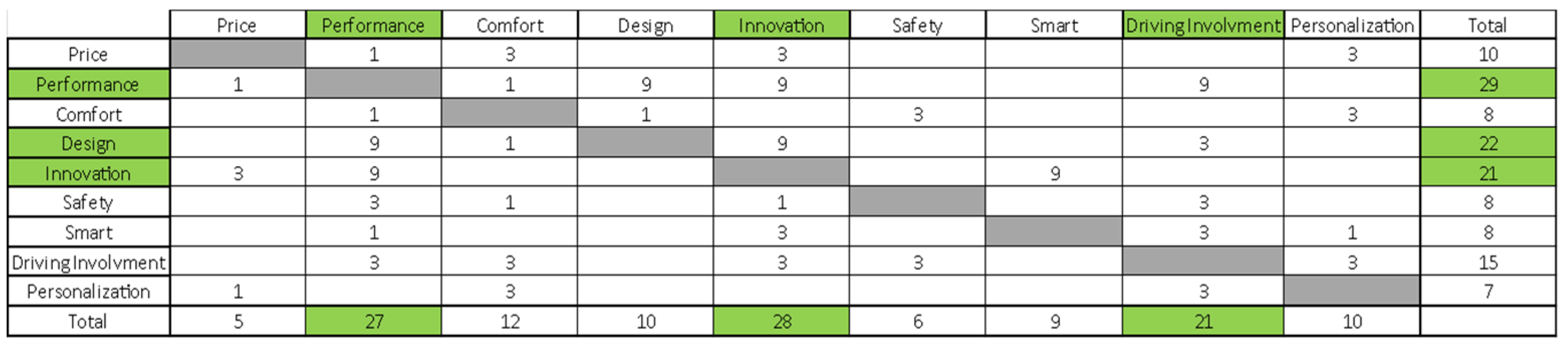
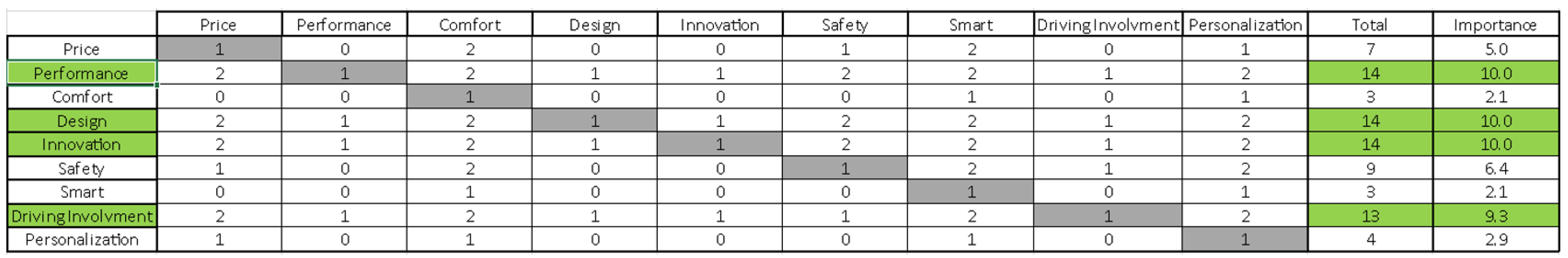
2.2.1. Independence Matrix and Importance Matrix
- A value of 1 for a weak relationship;
- A value of 3 for a medium relationship;
- A value of 9 for strong dependency.
- 0 if the element in the row is less important than the element of the column.
- 1 if they have the same importance.
- 2 if the element in the row is more important than the element in the column.
2.2.2. Benchmarking Analysis and Top–Flop Analysis
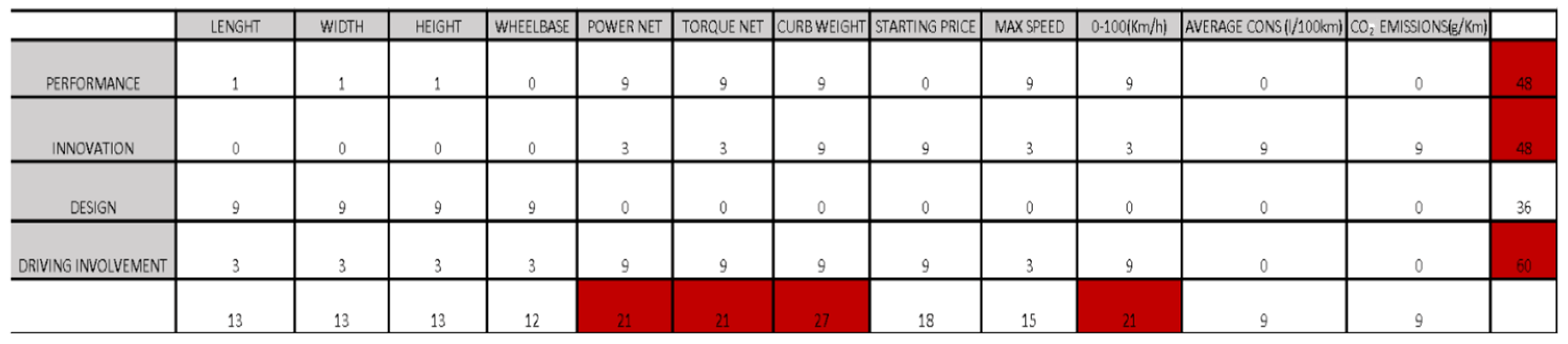
2.2.3. What–How Matrix
- 0 means no relation;
- 1 means weak relation;
- 3 means medium relation;
- 9 means strong relation.
- Performance;
- Innovation;
- Driving involvement.
- Power net;
- Torque net;
- Curb weight;
- 0–100(Km/h).
3. Results
3.1. Product Architecture
3.2. Innovation
3.2.1. Materials
- 2D shaping of sheets;
- 3D shaping in mold;
- Resin injection in the press putting together all the pieces (CFRP and Al. parts);
- Removing the monocoque chassis from the press;
- CNC machining to refine and open holes.
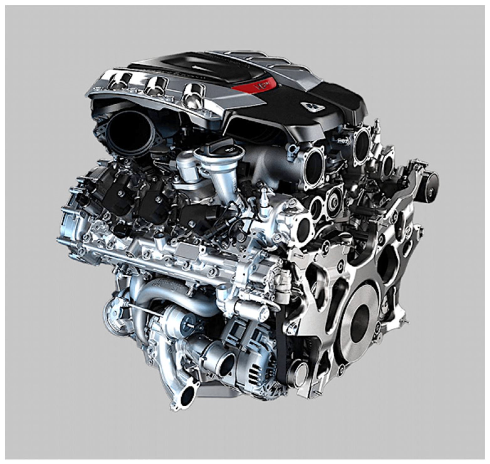
3.2.2. Power and Torque
3.2.3. Considerations and Criticisms on the Choice of Hydrogen and HYICE
3.2.4. How to Obtain Hydrogen
- Methane reforming;
- Coal gasification;
- Algae and bacteria;
- Electrolysis.
3.3. Two-Dimensional Architecture and Sketching
3.3.1. Retro
3.3.2. Stone
3.3.3. Natural
3.3.4. Advanced
3.3.5. Blueprints
- Retro: 0.49;
- Stone: 0.39;
- Advanced: 0.50;
- Natural: 0.45.
3.4. Three-Dimensional Architecture
3.5. Three-Dimensional Surface
3.6. CFD Analysis of the Final Model
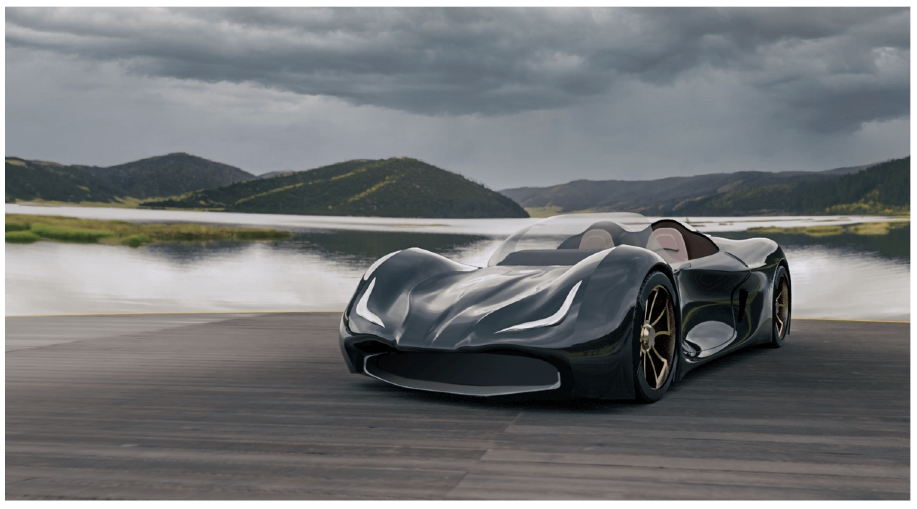
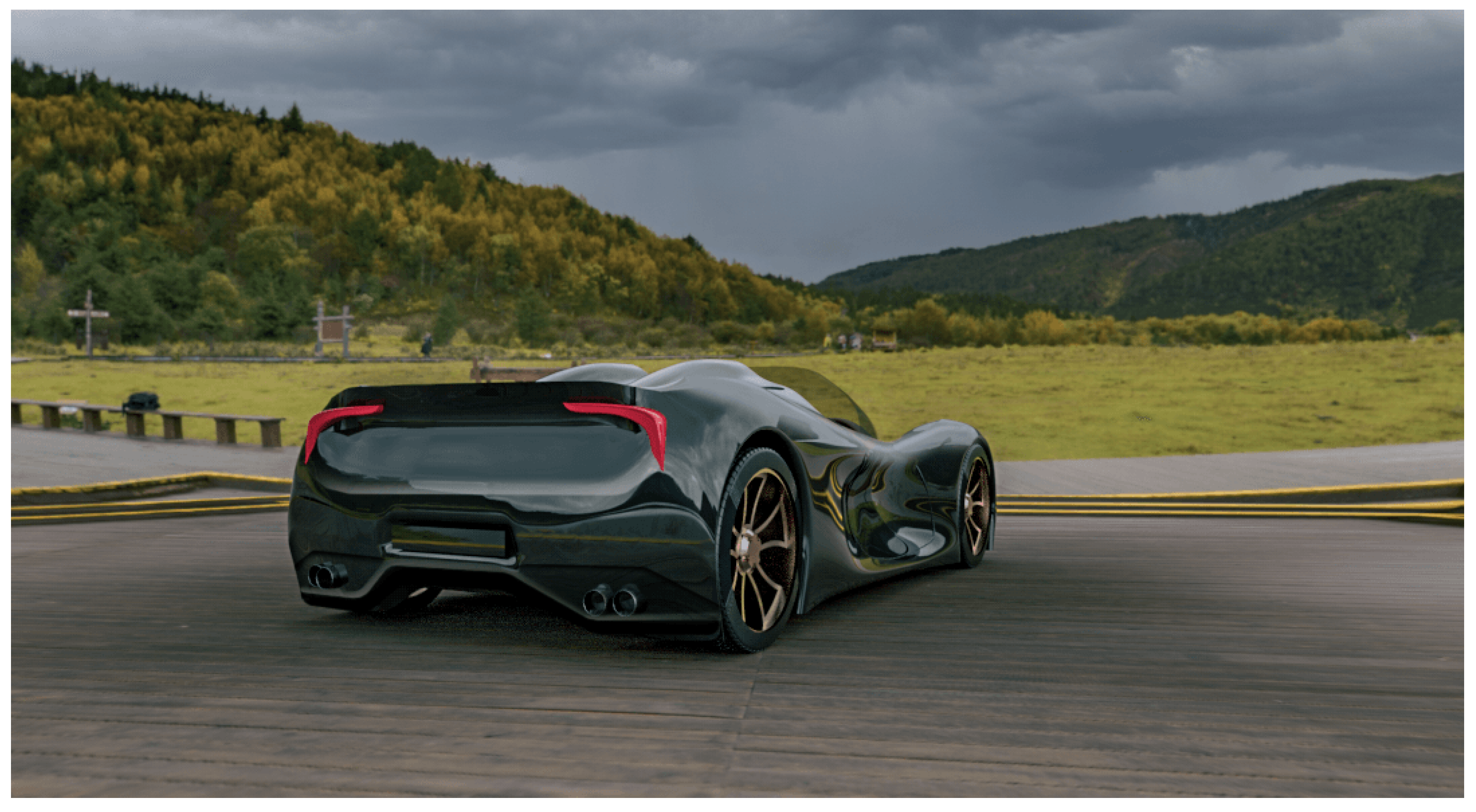
3.7. Rendering
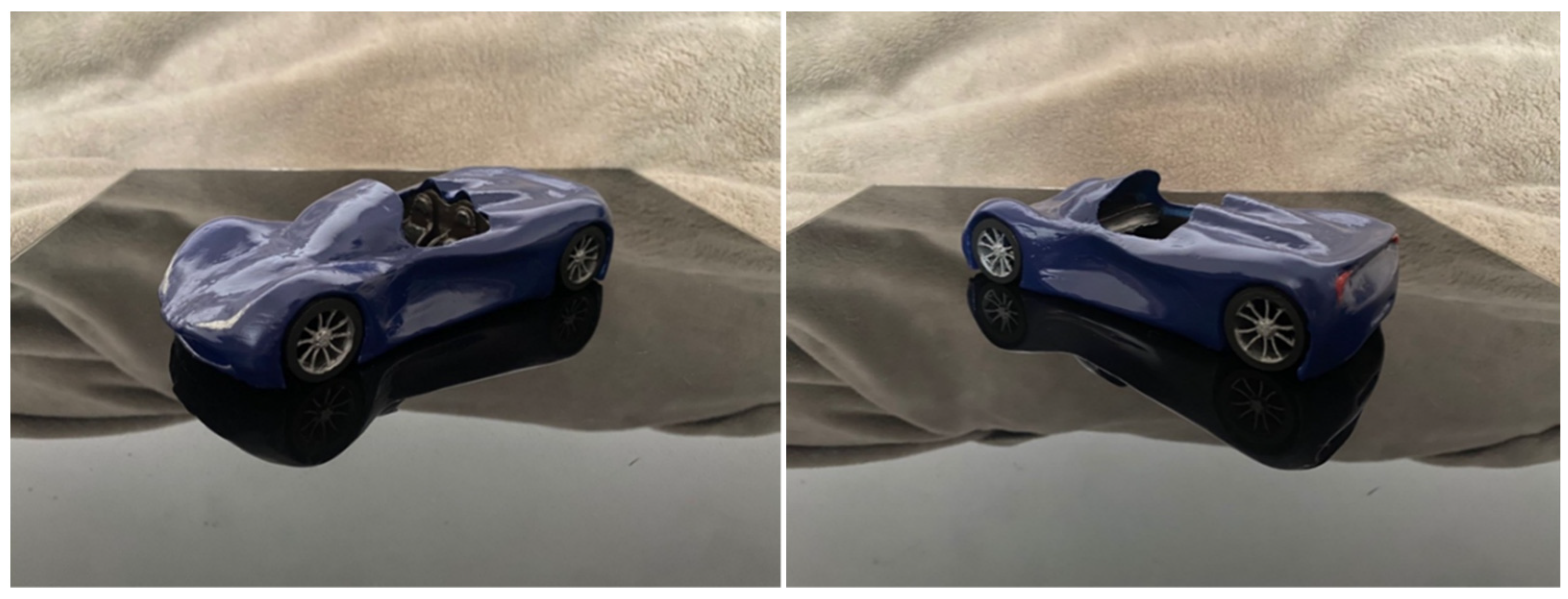
3.8. Prototyping
4. Discussion
5. Conclusions
- power development;
- re-design and adjustment of the chassis based on future developments of the propulsion and hydrogen storage system;
- development of vehicle dynamics;
- production strategies;
- any changes based on market trends.
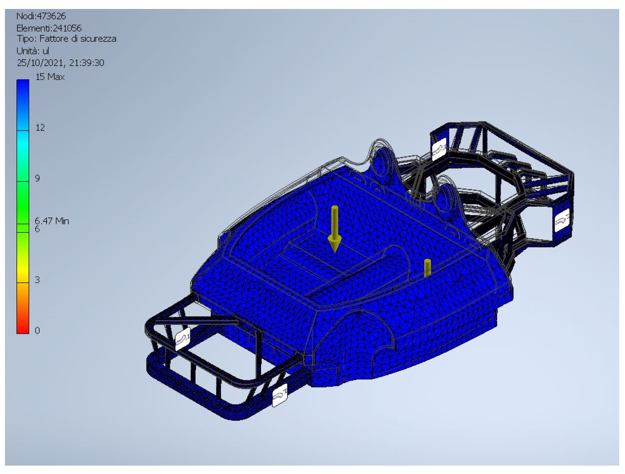
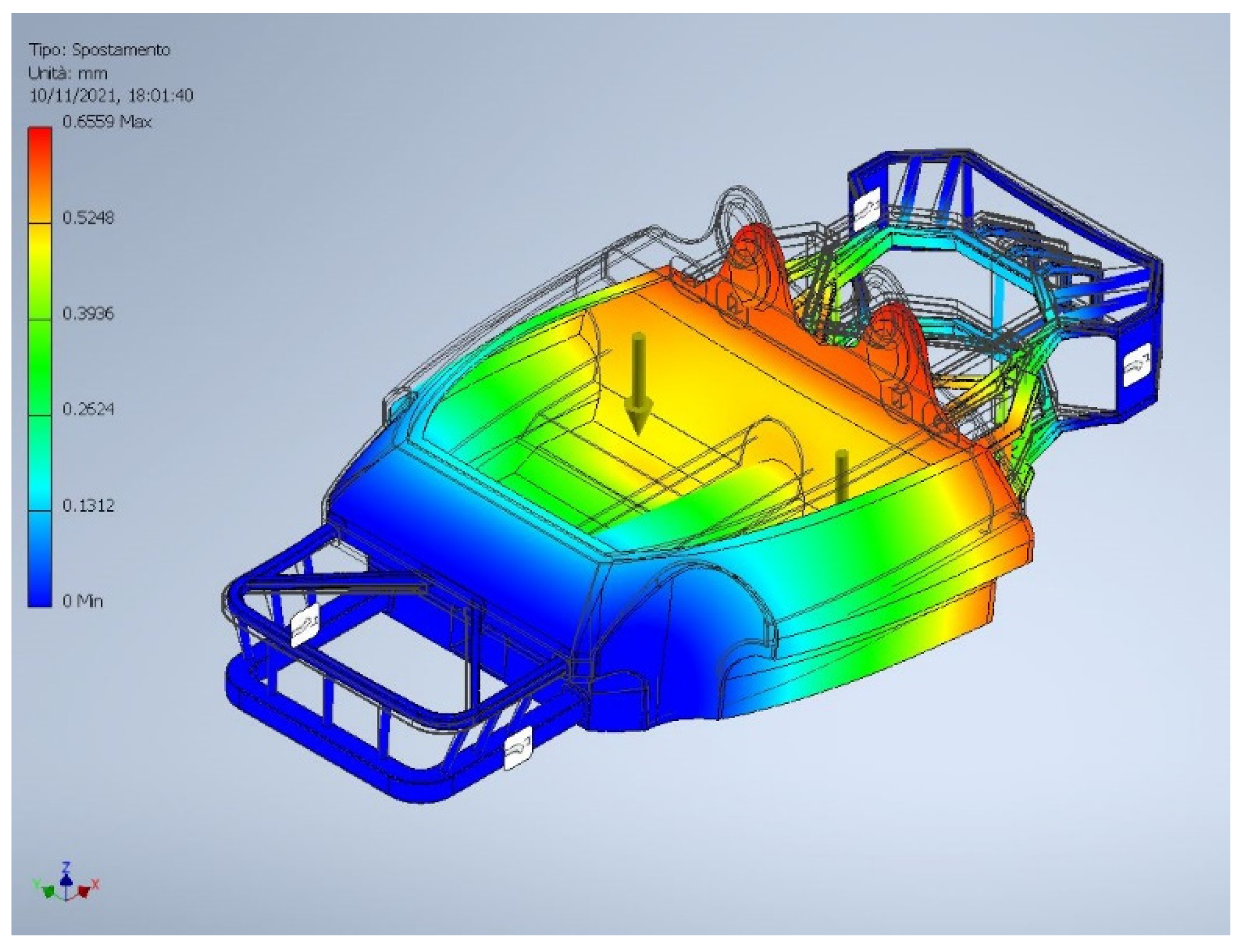
F.E.M. Analysis
Author Contributions
Funding
Acknowledgments
Conflicts of Interest
References
- Luo, Q.H.; Hu, J.B.; Sun, B.G.; Liu, F.S.; Wang, X.; Li, C.; Bao, L.Z. Experimental Investigation of Combustion Characteristics and NOx Emission of a Turbocharged Hydrogen Internal Combustion Engine. Int. J. Hydrogen Energy 2019, 44, 5573–5584. [Google Scholar] [CrossRef]
- Capparella, D. Iniezione Di Idrogeno Nei Motori a Combustione Interna; Lulu.com. 2019. Available online: https://books.google.com.hk/books/about/INIEZIONE_DI_IDROGENO_NEI_MOTORI_A_COMBU.html?id=ozqFDwAAQBAJ&redir_esc=y (accessed on 15 November 2022).
- Sun, B.; Bao, L.; Luo, Q. Development and Trends of Direct Injection Hydrogen Internal Combustion Engine Technology. J. Automot. Saf. Energy 2021, 12, 265. [Google Scholar] [CrossRef]
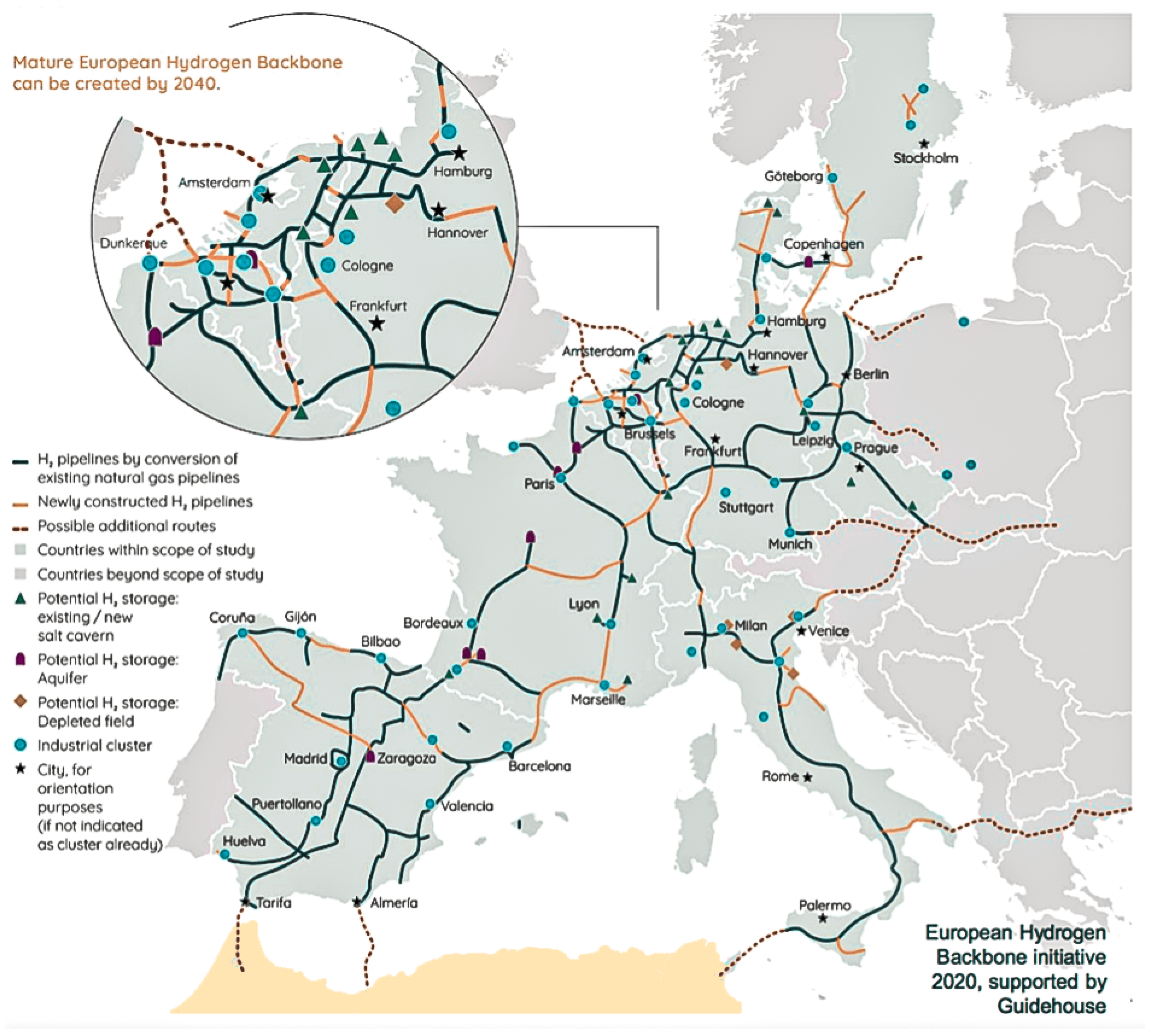
- Haeseldonckx, D.; D’haeseleer, W. The Use of the Natural-Gas Pipeline Infrastructure for Hydrogen Transport in a Changing Market Structure. Int. J. Hydrogen Energy 2007, 32, 1381–1386. [Google Scholar] [CrossRef]
- Gondal, I.A.; Sahir, M.H. Prospects of Natural Gas Pipeline Infrastructure in Hydrogen Transportation. Int. J. Energy Res. 2012, 36, 1338–1345. [Google Scholar] [CrossRef]
- Kojima, Y. Hydrogen Storage Materials for Hydrogen and Energy Carriers. Int. J. Hydrogen Energy 2019, 44, 18179–18192. [Google Scholar] [CrossRef]
- Yip, H.L.; Srna, A.; Yuen, A.C.Y.; Kook, S.; Taylor, R.A.; Yeoh, G.H.; Medwell, P.R.; Chan, Q.N. A Review of Hydrogen Direct Injection for Internal Combustion Engines: Towards Carbon-Free Combustion. Appl. Sci. 2019, 9, 4842. [Google Scholar] [CrossRef]
- Armaroli, N.; Balzani, V. The Hydrogen Issue. ChemSusChem 2011, 4, 21–36. [Google Scholar] [CrossRef]
- Verhelst, S. Recent Progress in the Use of Hydrogen as a Fuel for Internal Combustion Engines. Int. J. Hydrogen Energy 2014, 39, 1071–1085. [Google Scholar] [CrossRef]
- McTaggart-Cowan, G.; Mann, K.; Huang, J.; Singh, A.; Patychuk, B.; Zheng, Z.X.; Munshi, S. Direct Injection of Natural Gas at up to 600 Bar in a Pilot-Ignited Heavy-Duty Engine. SAE Int. J. Engines 2015, 8, 981–996. [Google Scholar] [CrossRef]
- Dennis, P.A.; Dingli, R.J.; Abbasi Atibeh, P.; Watson, H.C.; Brear, M.J.; Voice, G. Performance of a Port Fuel Injected, Spark Ignition Engine Optimised for Hydrogen Fuel. SAE Tech. Pap. 2012. [Google Scholar] [CrossRef]
- Boretti, A.A.; Watson, H.C. Enhanced Combustion by Jet Ignition in a Turbocharged Cryogenic Port Fuel Injected Hydrogen Engine. Int. J. Hydrogen Energy 2009, 34, 2511–2516. [Google Scholar] [CrossRef]
- Li, G. Optimization Study of Pilot-Ignited Natural Gas Direct-Injection in Diesel Engines. SAE Trans. 1999, 108, 1739–1748. [Google Scholar]
- Boretti, A. Advances in Hydrogen Compression Ignition Internal Combustion Engines. Int. J. Hydrogen Energy 2011, 36, 12601–12606. [Google Scholar] [CrossRef]
- Boretti, A.A. Diesel-like and HCCI-like Operation of a Truck Engine Converted to Hydrogen. Int. J. Hydrogen Energy 2011, 36, 15382–15391. [Google Scholar] [CrossRef]
- Trommer, S.; Kolarova, V.; Fraedrich, E.; Kröger, L.; Kickhöfer, B.; Kuhnimhof, T.; Lenz, B.; Phleps, P. Autonomous Driving—The Impact of Vehicle Automation on Mobility Behaviour. 2016. Available online: https://elib.dlr.de/110337/ (accessed on 15 November 2022).
- Turgunboev, T.T.; Saidov, A.A. Prospective Of Hydrogen in Automobile Transport. Acta Turin Polytech. Univ. Tashkent 2019, 9, 5. [Google Scholar]
- Horn, M.; MacLeod, J.; Liu, M.; Webb, J.; Motta, N. Supercapacitors: A New Source of Power for Electric Cars? Econ. Anal. Policy 2019, 61, 93–103. [Google Scholar] [CrossRef]
- Tchetchik, A.; Zvi, L.I.; Kaplan, S.; Blass, V. The Joint Effects of Driving Hedonism and Trialability on the Choice between Internal Combustion Engine, Hybrid, and Electric Vehicles. Technol. Forecast. Soc. Chang. 2020, 151, 119815. [Google Scholar] [CrossRef]
- Karczewski, M.; Szczęch, L.; Polak, F.; Brodowski, S. Analysis of Electric Vehicles Efficiency and Their Influence on Environmental Pollution. J. KONES 2019, 26, 97–104. [Google Scholar] [CrossRef]
- Sobol, Ł.; Dyjakon, A. The Influence of Power Sources for Charging the Batteries of Electric Cars on CO2 Emissions during Daily Driving: A Case Study from Poland. Energies 2020, 13, 4267. [Google Scholar] [CrossRef]
- Mrozik, W.; Rajaeifar, M.A.; Heidrich, O.; Christensen, P. Environmental Impacts, Pollution Sources and Pathways of Spent Lithium-Ion Batteries. Energy Environ. Sci. 2021, 14, 6099–6121. [Google Scholar] [CrossRef]
- Temporelli, A.; Carvalho, M.L.; Girardi, P. Life Cycle Assessment of Electric Vehicle Batteries: An Overview of Recent Literature. Energies 2020, 13, 2864. [Google Scholar] [CrossRef]
- Sloman, A. Exploring Design Space and Niche Space. In Proceedings of the Fifth Scandinavian Conference on Artificial Intelligence, SCAI 1995, Trondheim, Norway, 29–31 May 1995. [Google Scholar]
- Pevec, D.; Babic, J.; Carvalho, A.; Ghiassi-Farrokhfal, Y.; Ketter, W.; Podobnik, V. A Survey-Based Assessment of How Existing and Potential Electric Vehicle Owners Perceive Range Anxiety. J. Clean. Prod. 2020, 276, 122779. [Google Scholar] [CrossRef]
- Hooftman, N.; Messagie, M.; Van Mierlo, J.; Coosemans, T. A Review of the European Passenger Car Regulations—Real Driving Emissions vs. Local Air Quality. Renew. Sustain. Energy Rev. 2018, 86, 1–21. [Google Scholar] [CrossRef]
- Eichlseder, H.; Benkenida, A.; Boyer, B. Optimisation of a H2 Powered Internal Combustion Engine (HYICE). In Proceedings of the Tra-Transport Research Arena Europe 2006, Goeteborg, Sweden, 12–15 June 2006. [Google Scholar]
- Gardner, B.; Abraham, C. What Drives Car Use? A Grounded Theory Analysis of Commuters’ Reasons for Driving. Transp. Res. Part F Traffic Psychol. Behav. 2007, 10, 187–200. [Google Scholar] [CrossRef]
- Frizziero, L.; Leon-Cardenas, C.; Galiè, G.; Liverani, A. Industrial Design Structure: A Straightforward Organizational Integration of DFSS and QFD in a New Industry and Market Reality. TQM J. 2023. [Google Scholar] [CrossRef]
- Ginting, R.; Ishak, A.; Malik, A.F.; Satrio, M.R. Product Development with Quality Function Deployment (QFD): A Literature Review. IOP Conf. Ser. Mater. Sci. Eng. 2020, 1003, 012022. [Google Scholar] [CrossRef]
- Hasibuan, A.; Parinduri, L.; Sulaiman, O.K.; Suleman, A.R.; Harahap, A.K.Z.; Hasibuan, M.; Rupilele, F.G.J.; Simarmata, J.; Kurniasih, N.; Achmad Daengs, G.S.; et al. Service Quality Improvement by Using the Quality Function Deployment (QFD) Method at the Government General Hospital. J. Phys. Conf. Ser. 2019, 1363, 012095. [Google Scholar] [CrossRef]
- Donnici, G.; Frizziero, L.; Liverani, A.; Buscaroli, G.; Raimondo, L.; Saponaro, E.; Venditti, G. A New Car Concept Developed with Stylistic Design Engineering (SDE). Inventions 2020, 5, 30. [Google Scholar] [CrossRef]
- Kim, G.W.; Park, Y.I.; Park, K. Topology Optimization and Additive Manufacturing of Automotive Component by Coupling Kinetic and Structural Analyses. Int. J. Automot. Technol. 2020, 21, 1455–1463. [Google Scholar] [CrossRef]
- Boretti, A. Hydrogen Internal Combustion Engines to 2030. Int. J. Hydrogen Energy 2020, 45, 23692–23703. [Google Scholar] [CrossRef]
- Rivard, E.; Trudeau, M.; Zaghib, K. Hydrogen Storage for Mobility: A Review. Materials 2019, 12, 1973. [Google Scholar] [CrossRef] [PubMed]
- Kim, D.J.; Lim, J.; Nam, B.; Kim, H.J.; Kim, H.S. Design and Manufacture of Automotive Hybrid Steel/Carbon Fiber Composite B-Pillar Component with High Crashworthiness. Int. J. Precis. Eng. Manuf.-Green Technol. 2021, 8, 547–559. [Google Scholar] [CrossRef]
- Sratong-On, P. Structural Design of a Full-Body Composite Monocoque Chassis Based on the Type of Carbon Fiber Fabrics. SAE Tech. Pap. 2022. [Google Scholar] [CrossRef]
- Freddi, M.; Ferretti, P.; Alessandri, G.; Liverani, A. Reverse Engineering of a Racing Motorbike Connecting Rod. Inventions 2023, 8, 23. [Google Scholar] [CrossRef]
- Journal, I.; Sarkar, S.; Thummar, K.; Shah, N.; Vagrecha, V. A Review Paper on Aerodynamic Drag Reduction and CFD Analysis of Vehicles. IRJET Int. Res. J. Eng. Technol. 2019, 6, 231–235. [Google Scholar]
- Damjanović, D.; Kozak, D.; Živić, M.; Ivandić, Ž.; Baškarić, T. CFD Analysis of Concept Car in Order to Improve Aerodynamics. Járműipari Innováció 2011, 1, 108–115. [Google Scholar]
- Ferretti, P.; Santi, G.M.; Leon-Cardenas, C.; Fusari, E.; Cristofori, M.; Liverani, A. Production Readiness Assessment of Low Cost, Multi-Material, Polymeric 3D Printed Moulds. Heliyon 2022, 8. [Google Scholar] [CrossRef]
- Saplinova, V.; Novikov, I.; Glagolev, S. Design and Specifications of Racing Car Chassis as Passive Safety Feature. Transp. Res. Procedia 2020, 50, 591–607. [Google Scholar] [CrossRef]
- Santi, G.M.; Francia, D.; Cesari, F. Explicit Analytical Shape Function Calculation for Macro-Element in Glue Connection. Mech. Adv. Mater. Struct. 2022, 29, 7025–7033. [Google Scholar] [CrossRef]


| Length (mm) | Width (mm) | Height (mm) | Wheelbase (mm) | Engine (cm3) | Powernet (kW) | Torque (Nm) | Curb Weight (kg) | Price (EUR) | |
|---|---|---|---|---|---|---|---|---|---|
| BMW Z4 30i | 4324 | 1864 | 1304 | 2470 | 1998 | 190 | 400 | 1415 | 53,000 |
| Audi TT 40 TFSI | 4191 | 1832 | 1355 | 2505 | 1984 | 145 | 320 | 1360 | 44,950 |
| Mazda MX-5 RF | 3915 | 1735 | 1236 | 2310 | 1998 | 135 | 205 | 1072 | 34,500 |
| Porsche Cayman S | 4397 | 1801 | 1284 | 2475 | 2497 | 257.5 | 420 | 1385 | 75,506 |
Disclaimer/Publisher’s Note: The statements, opinions and data contained in all publications are solely those of the individual author(s) and contributor(s) and not of MDPI and/or the editor(s). MDPI and/or the editor(s) disclaim responsibility for any injury to people or property resulting from any ideas, methods, instructions or products referred to in the content. |
© 2023 by the authors. Licensee MDPI, Basel, Switzerland. This article is an open access article distributed under the terms and conditions of the Creative Commons Attribution (CC BY) license (https://creativecommons.org/licenses/by/4.0/).
Share and Cite
Galiè, G.; Cappelli, M.; Maffei, P.; Robusti, M.; Vasileski, I.; Frizziero, L. Use of IDeS Method to Design an Innovative HYICE Sportscar. Inventions 2023, 8, 75. https://doi.org/10.3390/inventions8030075
Galiè G, Cappelli M, Maffei P, Robusti M, Vasileski I, Frizziero L. Use of IDeS Method to Design an Innovative HYICE Sportscar. Inventions. 2023; 8(3):75. https://doi.org/10.3390/inventions8030075
Chicago/Turabian StyleGaliè, Giulio, Michele Cappelli, Pietro Maffei, Matteo Robusti, Igor Vasileski, and Leonardo Frizziero. 2023. "Use of IDeS Method to Design an Innovative HYICE Sportscar" Inventions 8, no. 3: 75. https://doi.org/10.3390/inventions8030075