
Quantum Power Electronics: From Theory to Implementation

Department of Electrical and Computer Engineering, Aarhus University, 8200 Aarhus, Denmark
*
Author to whom correspondence should be addressed.
Inventions 2023, 8(3), 72; https://doi.org/10.3390/inventions8030072
Submission received: 21 February 2023
/
Revised: 4 May 2023
/
Accepted: 5 May 2023
/
Published: 16 May 2023
(This article belongs to the Collection Feature Innovation Papers)
Abstract
:While impressive progress has been already achieved in wide-bandgap (WBG) semiconductors such as 4H-SiC and GaN technologies, the lack of intelligent methodologies to control the gate drivers has prevented exploitation of the maximum potential of semiconductor chips from obtaining the desired device operations. Thus, a potent ongoing trend is to design a fast gate driver switching scheme to upgrade the performance of electronic equipment at the system level. To address this issue, this work proposed a novel intelligent scheme for the control of gate driver switching using the concept of quantum computation in machine learning. In particular, the quantum principle was incorporated into deep reinforcement learning (DRL) to address the hardware limitations of conventional computers and the growing amount of data sets. Taking potential benefit of the quantum theory, the DRL algorithm influenced by quantum specifications (referred to as QDRL) not only ameliorates the performance of the native algorithm on traditional computers but also enhances the progress of relevant research fields like quantum computing and machine learning. To test the practicability and usefulness of QDRL, a dc/dc parallel boost converter feeding constant power loads (CPLs) was chosen as the case study, and several power hardware-in-the-loop (PHiL) experiments and comparative analysis were performed.
1. Introduction and Preliminaries
The continual requests for more packed PCB footprints have pushed power electronic researchers to develop novel configurations with fewer components, compacting technologies, and utilizing advanced semiconductors which can promote power density. When providing regulated power to on-board semiconductors, the significance of switching frequency appears immediately clear to systems designers. Systems designers soon realize the significance of switching frequency when supplying regulated power to on-board semiconductor devices. It is desirable to enhance the regulator frequency since this can lead to reducing the size and board footprint needs of the related passive components such as capacitors, resistors, etc. The primary transistors were manufactured by Silicon (Si) for many decades, although Si suffers significant constraints in relation to the operation temperature, light transmission, switching frequency, etc. [1]. Currently, the maximum breakdown voltage strength of a commercial Si-insulated gate bipolar transistor (IGBT) is 8.4 kV with a limited switching operation, while the permissible temperature of any Si-based device is less than 200 °C [1,2]. To achieve superior performance in terms of efficiency, switching speed, and compactness, wide-bandgap (WBG) semiconductors were developed as a good option to displace conventional Si-based products into electronics equipment.
Among the most popular WBG materials, silicon carbide (4H-SiC) and gallium nitride (GaN) offer a higher level of breakdown capability, greater heat conductivity, greater switching frequency, and greater carrier saturation drift speed [3]. The first generation of GaN semiconductors, especially high electron mobility transistors, were fabricated in a lateral structure due to initial challenges in the GaN substrates. Despite the success of the radio-frequency power field [4], the limitations of the peak electric field in the lateral configuration led to the low-voltage band (650 V) in the GaN-based HEMTs. With the recent progress in the commercial GaN bulk substrates, a higher breakdown voltage with thinner drift layers is reachable using the new generations of GaN devices in the vertical structure [5]. The utilization of the two-dimensional electron gas formation has enabled the possibility of high-frequency switching capability in the vertical AlGaN/GaN heterostructures, where mobility values are usually more than 1000 square centimeters . Unlike their GaN counterparts, the SiC semiconductors have been adopted as a promising material for low-frequency and high-voltage power applications [6]. Due to their high gate charge and need for high-power gate circuits, SiC devices are often adopted at low frequencies. However, the increasing demand for SiC components faces the bulkiness of the gate driver circuits and design complexity. The authors of [7] demonstrated that a 2-kW Class Φ2 inverter with the SiC MOSFET has a lower volume than the Si-based gate driver. The deployment of integrated SiC-based gate drivers, according to recent state-of-the-art semiconductor studies [8,9], led to lighter and more compact power electronic devices. While semiconductor chips delivered remarkable progress at the device level, no matching advances have been observed at the system level (drivers, control algorithms, etc.), and as a result, a large portion of that potential is being lost.
Proper regulation of the gate driver in order to accomplish minimization, high efficiency, and size reduction—all of which are related to the switching frequency—is the essential strategy for maximizing the benefits of semiconductors. For the design of intelligent gate drivers, many practical experiments include widely soft-switching techniques to reach enhanced efficiency and high-speed switching using reducing losses which can be derived by zero-voltage or zero-current transitions. To make further advancements without efficiency deterioration, numerous auxiliary-circuit-based (i.e., hardware-based) approaches, such as quasi-resonant, multiple-resonant, and series/parallel/series-parallel resonant have been introduced [10]. Despite the high efficiency of deploying such auxiliary circuits, their design not only leads to the increasing cost and overall dimension of a power device but also creates conduction loss because of the circulating currents in the auxiliary components. To address these issues, many nonauxiliary-circuit-based methodologies (i.e., software-based) such as single/dual phase-shift, phase-shift modulation, and trapezoidal modulation, (which add a higher level of reliability with reduced cost because there are no unnecessary auxiliary components), were reported to control gate drivers [11]. However, these techniques are complex to regulate, and the zero-voltage-switching (ZVS) may malfunction within the full-power range because of the limited gain ratio; hence, their application is limited in low and medium power systems.
With the progress of big data and artificial intelligence, machine learning (ML) has the potential to revolutionize the next generation of power electronic interfaces and make a substantial impact in terms of efficiency and reliability. Quantum ML (QML) is a field that aims to fully integrate conventional ML and quantum information processing (QIP) to address and overcome the issues that have been seen in the algorithmic tasks of conventional ML (e.g., time-consuming, data acquisition, and kernel estimation). On the basis of the algorithmic process, many proposals were made in the context of QML including supervised, unsupervised, and semi-supervised learning. In contrast, fewer state-of-the-art studies pay attention to the development of reinforcement learning (RL) in the QML community, and in particular, proposals for quantum process deep RL (QPDRL) are becoming an emerging field. The concept of QPDRL first emerged in 2008 [12] from incorporating the principle of quantum parallelism into traditional reinforcement learning, which provided the right balance between exploration and exploitation and accelerated training as well. Dunjko et al. [13] theoretically demonstrated that with the application of QPDRL, a quadratic amelioration in the training efficiency and exponential amelioration in the operation would be provided for a wide class of training problems. The QPDRL with multiqubit has also been tested on state-of-the-art superconducting circuits [14] and expanded to include multilevel systems and open quantum dynamics, among other scenarios [15]. Additionally, recent studies [16] have shown that employing quantum Boltzmann machines for RL is advantageous compared to using a conventional one.
Unlike the circuit designs and configurations that have less importance in taking the full benefits of GaN and 4H-SiC, the proper control of the gate driver is the key option for benefiting the maximum potential of advanced semiconductors at the system level. The paradigm shift from today’s gate driver control methodologies to innovative ultra-superfast schemes and design tools is required to offer a higher level of efficiency for power electronic interfaces and motor drivers, resulting in realistically improving compactness and reducing energy consumption.
The primary objective of this work was to control the gate driver using advanced control methodology for the high-frequency converter. Taking the benefits of quantum theory, an intelligent gate driver based on Quantum DRL was designed based on the nature of subatomic particles to conduct the computations several times faster than the most sophisticated algorithms. The real-time examinations based on the OPAL-RT setup were accomplished with a comparison-to-model predictive control.
The remainder of this work is organized as follows: The dynamic modeling of the power electronic test system is presented in Section II. The theory of ultra-local model control is introduced in Section III. In Section IV, the framework of QPDRL is introduced and quantum representations and quantum operations are presented, followed by the algorithm description of QPDRL with specific implementation details. In Section V, the experimental results are presented to verify the applicability of the proposed QPDRL algorithm.
2. Materials and Methods
2.1. Dynamics of DC MG with Parallel Boost Converter
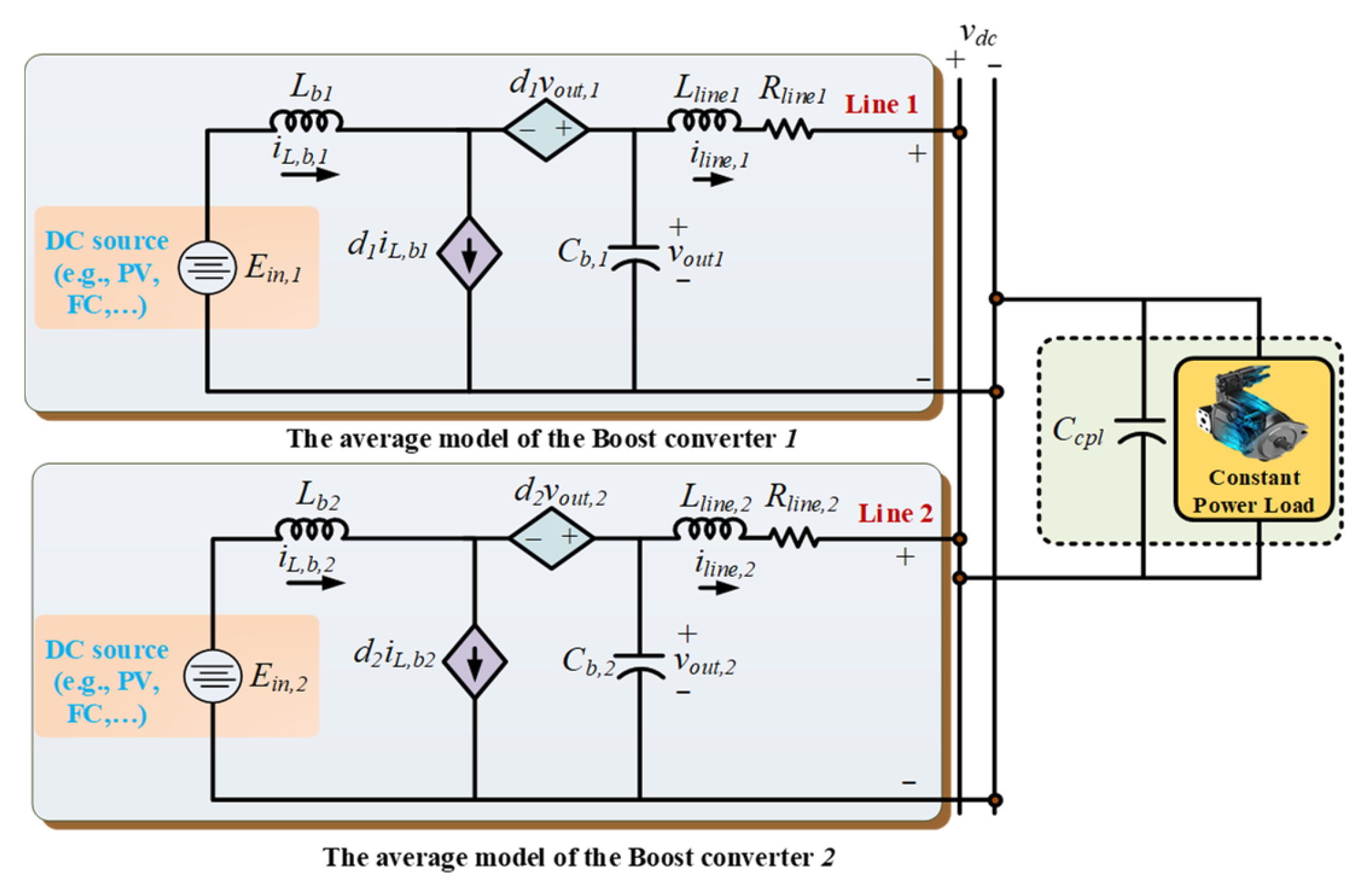
Figure 1 represents the simplified model and typical configuration of a DC power electronic system comprising two boost converters. In the structure, the boost converters are connected as parallel to transfer the power from the DC voltage source (e.g., photovoltaic, fuel cell, etc.) which is connected to the main bus to supply the CPL [17].
In Figure 1, , , and denote the inductance and capacitor of converters, respectively; and denote the line resistance and line inductance, respectively. denotes the CPL’s power and denotes the CPL’s capacitor. denotes the transmission line current of the converter; and denote the input voltages of converter-1 and converter-2, respectively; and are the output signals of converter-1 and converter-2, respectively.
The average model of the converter is expressed as:
The equations corresponding to the power converter are given as:
The main role of the controller in the power electronic system is to the output voltage , which tracks the reference’s voltage .
2.2. Structure of Ultra-Local Model Control
Assume the dynamic model of a system is unknown and can be described by a single-input single-output (SISO) system. The ultra-local model (ULM) of the system can be defined to determine the unknown mathematical model. For a SISO system, the input–output behavior of the system can be expressed by [18]:
where is an unknown function with a smooth function of its arguments, and are the orders of and , respectively, and is defined as:
where , . A numerical model of (6) can be described by ULM for a very short lapse of the interval, given as:
where is a non-physical factor selected such that the and will have the same order, and term includes all the unmodelled dynamics which are often calculated by the algebraic approach.
The expression of the law control for a unit derivative order can be formed as an intelligent proportional-integral (iPI) controller:
where denotes the estimation of unmodeled dynamics, and and are the tunable parameters of the iPI controller.
2.3. Quantum Deep Reinforcement Learning
The reduction of reinforcement learning (RL) actions is necessary to counteract the dimensionality curse, however, fewer command numbers may result in incorrect control signals. By adopting the Quantum mechanism, a higher level of control signals can be generated than the action set in the standard RL. In this way, deep belief networks (DBNs) can be adopted to predict the next systemic information which would lead to accurate control commands.
2.3.1. Principal of Quantum Theory
The quantum bit (qubit), which functions similarly to traditional bits, is regarded as the core idea of quantum computation. In quantum theory, two basic levels of the qubit are defined by and , which are equivalent to the traditional bit states of 0 and 1. However, a qubit can be expressed based on a superposition state of and regarding complex coefficients of and , given as [19]:
An RL agent interacts with its environment which is mathematically formulated by the Markov decision process (MDP). The th output of the quantum process based on DRL can be obtained by the following descriptions:
where and denote the actions of set ; the selected action among the possible actions of is shown by . Likewise, is the output probability which is expressed by:
where ; is a complex factor; denotes the occurrence probability of in the action ; is the quantum bit count.
2.3.2. Principal of RL
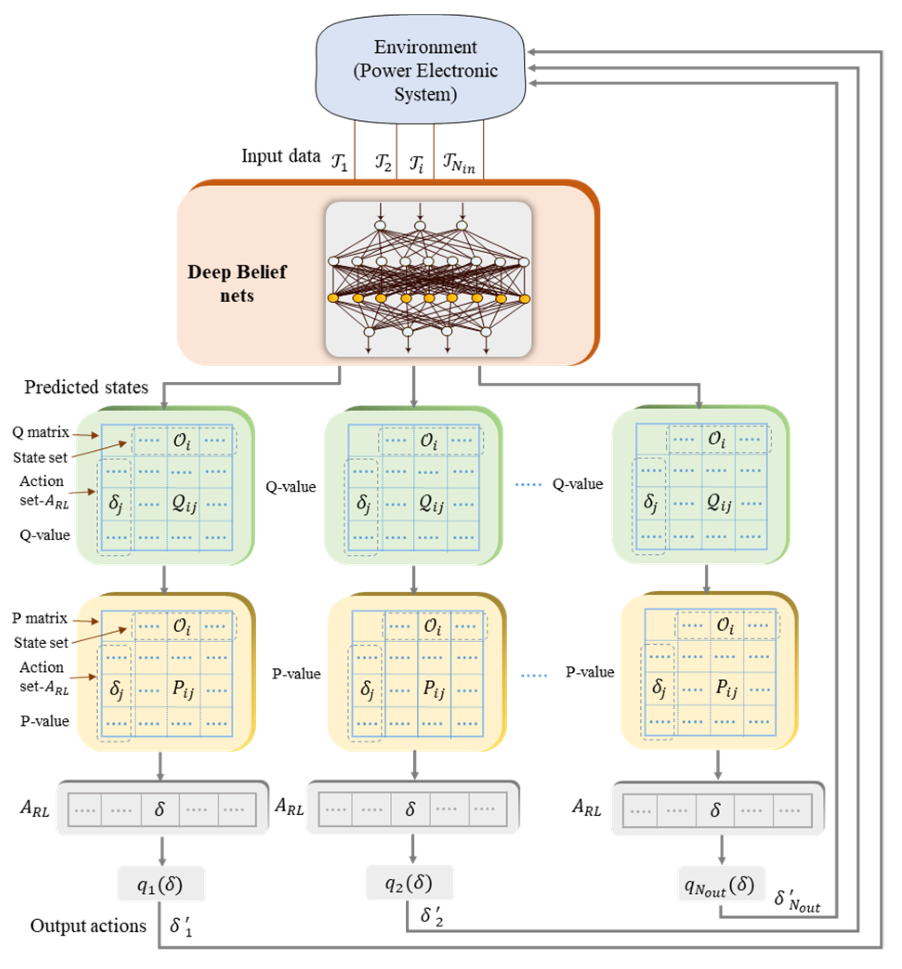
Each subordinate RL was made from four parts: (i) a Q-value renovated activity, (ii) a p-value renovated activity, (iii) an action selection mechanism, and (iv) a quantum procedure. With the state prediction of DBNs, the Q-value of each subsidiary component could be updated. In the next stage, the p-value was updated by the p-value process, providing the p-value mechanism to acquire the action index. Then, the actions were chosen from the actions set . In the final stage of QDRL, the quantum process generated real actions. The control actions of the QDRL-agent were provided by updating the Q-value matrix and p-value matrix, given as [16]:
In the above equations, , , and denote the learning factor, discount factor, and updated factor, respectively. Generally, all the parameters of , , and are configured in the band of , , and . The terms of , , and are the current state, action, and anticipated next state, correspondingly. The reward function of QPDRL for a wide range of power electronic test systems can be defined as:
where and denote the constant coefficients.
2.3.3. Deep Belief Nets (DBNs) Based on Restricted Boltzmann Machines
The deep belief nets (DBNs) are potent generative models which employ a deep structure of multiple restricted Boltzmann machines (RBM). In the DBNs, it is assumed that the number of hidden layers and hidden units are equal. By considering the set of one can have [20]:
where represents a linking matrix of RBM; represents the biases of hidden neurons; represents the visible neurons; the vectors of , and represents the property of visible and hidden layers.
The distribution of marginal probability based on the term is given as:
For the hidden and visible units, the dynamic probability distribution can be calculated by employing a Gibbs sampling approach, given as:
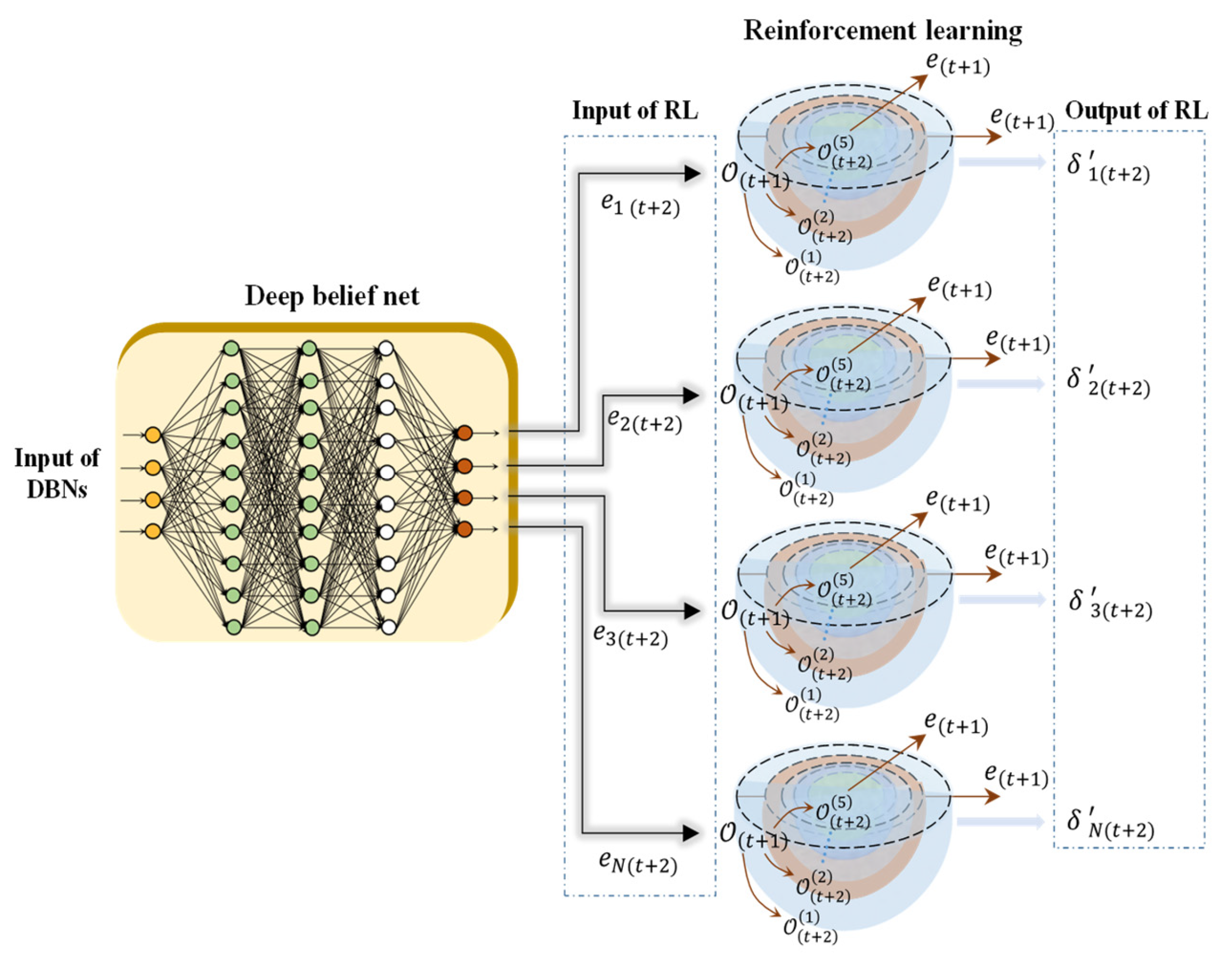
A detailed illustration of the QPDRL is depicted in Figure 2.
2.3.4. Training of QPDRL
For the power electronic test system, the terms of , , and were considered as the input data parameters of the QPDRL. The four variables of output voltages were estimated by the deep nets, i.e., , , , and . The training framework of the QPDRL is illustrated in Figure 3 [16]. By training the deep belief nets, the accurate prediction of the system states was realized. The control actions generated in the output of QPDRL adjusted the control coefficients of the ULM controller, i.e., and .
3. Results
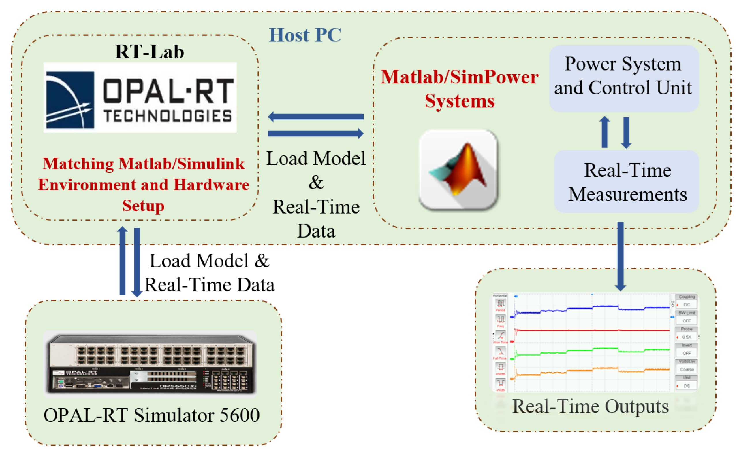
The DC power electronic system in this paper was developed in a laboratory OPAL-RT setup to conduct hardware-in-the-loop (HiL) simulations for real-time examinations of the proposed control methodology (Figure 4). For comparison, the real-time outcomes of the ULM controller based on QPDRL were compared with the PID controller and MPC.
The values of inductance for the boost converter were set to ; the values of resistance of bus line-1 and bus line-2 were given as and , respectively; the values of the capacitor of the boost converter were ; the inductance of the bus line-1 and line-2 were given as and , respectively.
3.1. Case Study (i) (under Change in CPL’s Power)
The DC source voltage for both the converters was set as 500 [V] while the output voltages of CPL were regulated on 750 [V]. It should be noted that change in the CPL’s power imposed the worst condition of instability on the power electronic systems. Thus, a time-varying CPL’s power for 0–2.4 s was applied on the dc-dc converter, given as:
The CPL’s power, voltage, and current waveforms of the HiL setup under the CPL’s power of (19) for the PID controller, MPC and the proposed controller are shown in Figure 5a, Figure 5b and Figure 5c, respectively. As shown in the HiL outcomes, the system responses with various designed controllers were affected by the change in the CPL’s power. It was evident that the voltage outcomes of the proposed ULM controller (with maximin overshoot 785), which were realized based on the QPDRL, experienced lower fluctuations than the PID controller (with maximin overshoot 875) and the MPC controller (with maximin overshoot 860). Therefore, a higher level of robustness could be reached by the proposed ULM controller-based QPDRL than the other state-of-the-art schemes from the stability point of view.
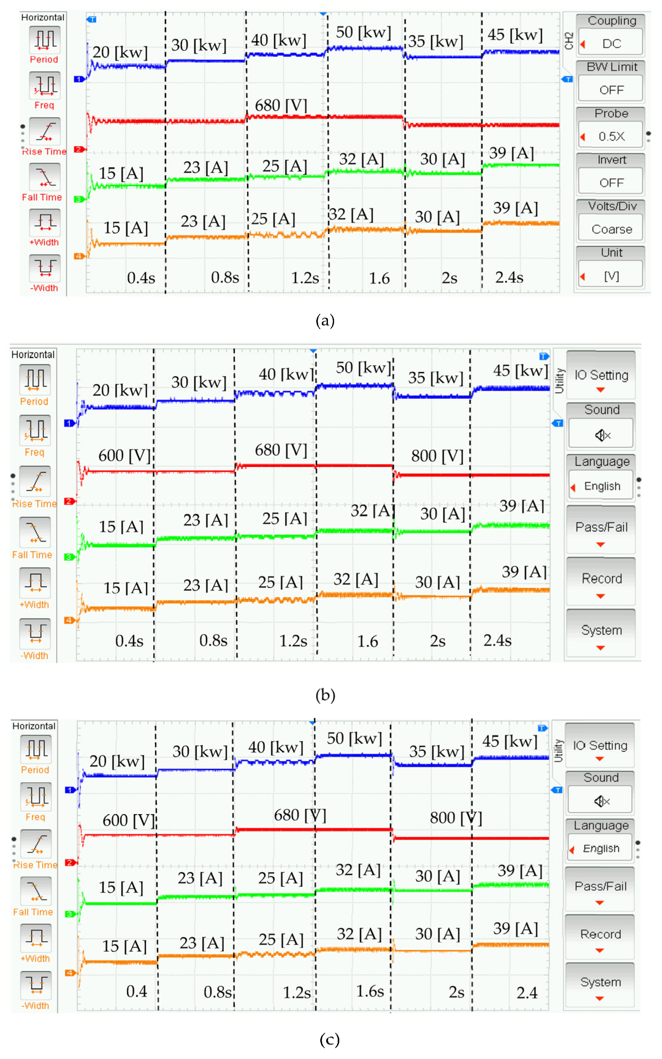
3.2. Case Study (ii) (under a Change in CPL’s Power and Reference’s Voltage)
In this case, the reference voltage and power of the CPLs were changed simultaneously during the experiment to examine the performance of the designed controller in more severe conditions. The reference voltage was set to [V] for [0 0.8 s), [V] for [0.8 s 1.6 s), and [V] for [1.6 s 2.4 s]. The values of the CPL’s power, voltage, and the current outputs of the power electronic test system with parallel boost converters under changes in the CPL’s power and reference voltage for the PID controller, MPC, and the proposed controller are depicted in Figure 6a, Figure 6b and Figure 6c, respectively. Despite the fact that the PID controller and the MPC could stabilize the system outputs, their performance was not optimal during the changes in the CPL’s power and reference voltage. However, the proposed controller with QPDRL effectively regulated the system outputs with better transient responses than the two other controllers.
4. Discussion
This paper focused on the design of the fast-switching power converters using the fundamentals of quantum process. The control of the parallel configuration of power converters feeding the constant power loads have been realized based on the quantum process of deep reinforcement learning to improve the performance of power electronic systems at the system level. In the following summary, the main advantages of the proposed scheme are presented.
- (1)
- Compared with the conventional control methodologies, a fast-switching scheme for the control of the gate-driver was proposed.
- (2)
- While recent works focused on the development of transistor technologies, the proposed scheme improved the performance of the power converters at the system level.
- (3)
- While the quantum-based control methodologies have high-performance computing (HPC) which necessitates the use of supercomputers, quantum deep reinforcement learning can be executed using classic computers.
- (4)
- Since the high level of frequency switching can be realized by the quantum concept, more compact power electronic systems can be built.
5. Conclusions
The suggested quantum process-based DRL scheme was exhaustively evaluated by means of HiL experiments accomplished in a 20 KW DC multi-converter supplying CPL. To appraise the actual application of QPDRL beyond the proof of concept presented in this work, it is essential to compare QPDRL with many state-of-the-art RL algorithms, in a power electronic test system. The HiL experiments using the OPAL-RT setup revealed that a rich impressibility of the quantum QPDRL contributed to reaching the accurate voltage regulation for the parallel boost converters. Despite severe instability imposed by the time-varying CPL, the proposed scheme was still stable while providing a higher level of output regulation in terms of a transient response and steady state.
Author Contributions
Investigation, M.G.; supervision, M.-H.K. All authors have read and agreed to the published version of the manuscript.
Funding
This research received no external funding.
Data Availability Statement
It is not available.
Conflicts of Interest
The authors declare no conflict of interest.
References
- Han, L.; Liang, L.; Kang, Y.; Qiu, Y. A review of SiC IGBT: Models, fabrications, characteristics, and applications. IEEE Trans. Power Electron. 2020, 36, 2080–2093. [Google Scholar] [CrossRef]
- Sun, X.; Huang, K.; Zhu, X.; Shao, H.; Wang, Y.; Chi, P.-L.; Yang, T. A 2–10 GHz Reconfigurable GaN Power Amplifier with Average Power-added Efficiency of 30% and Output Power of 2W. IEEE Trans. Circuits Syst. II Express Briefs 2022, 70, 964–968. [Google Scholar]
- Shah, F.M.; Xiao, H.M.; Li, R.; Awais, M.; Zhou, G.; Bitew, G.T. Comparative performance evaluation of temperature dependent characteristics and power converter using GaN, SiC and Si power devices. In Proceedings of the 2018 IEEE 12th International Conference on Compatibility, Power Electronics and Power Engineering (CPE-POWERENG 2018), Doha, Qatar, 10–12 April 2018; pp. 1–7. [Google Scholar]
- Liu, Y.; Lv, Y.; Guo, S.; Luan, Z.; Cheng, A.; Lin, Z.; Yang, Y.; Jiang, G.; Zhou, Y. A novel AlGaN/GaN heterostructure field-effect transistor based on open-gate technology. Sci. Rep. 2021, 11, 22431. [Google Scholar] [CrossRef] [PubMed]
- Fu, H.; Fu, K.; Chowdhury, S.; Palacios, T.; Zhao, Y. Vertical GaN power devices: Device principles and fabrication technologies—Part I. IEEE Trans. Electron Devices 2021, 68, 3200–3211. [Google Scholar] [CrossRef]
- Singh, S.; Chaudhary, T.; Khanna, G. Recent advancements in wide band semiconductors (SiC and GaN) technology for future devices. Silicon 2021, 14, 5793–5800. [Google Scholar] [CrossRef]
- Choi, J.; Tsukiyama, D.; Rivas, J. Comparison of SiC and eGaN devices in a 6.78 MHz 2.2 kW resonant inverter for wireless power transfer. In Proceedings of the 2016 IEEE Energy Conversion Congress and Exposition (ECCE), Milwaukee, WI, USA, 18–22 September 2016; pp. 1–6. [Google Scholar]
- Rothmund, D.; Bortis, D.; Kolar, J.W. Highly compact isolated gate driver with ultrafast overcurrent protection for 10 kV SiC MOSFETs. CPSS Trans. Power Electron. Appl. 2018, 3, 278–291. [Google Scholar] [CrossRef]
- Hu, J.; Zhao, X.; Ravi, L.; Burgos, R.; Dong, D. Enhanced Gate Driver Design for SiC-Based Generator Rectifier Unit for Airborne Applications. In Proceedings of the 2021 IEEE Applied Power Electronics Conference and Exposition (APEC), Phoenix, AZ, USA, 14–17 June 2021; pp. 2526–2531. [Google Scholar]
- Mohammed, S.A.Q.; Jung, J.-W. A State-of-the-Art Review on Soft-Switching Techniques for DC–DC, DC–AC, AC–DC, and AC–AC Power Converters. IEEE Trans. Ind. Inform. 2021, 17, 6569–6582. [Google Scholar] [CrossRef]
- Zengin, S. A hybrid current modulated DAB DC/DC converter for connecting PV modules to DC grid considering partial shading. Comput. Electr. Eng. 2022, 101, 108109. [Google Scholar] [CrossRef]
- Dong, D.; Chen, C.; Li, H.; Tarn, T.-J. Quantum reinforcement learning. IEEE Trans. Syst. Man Cybern. Part B Cybern. 2008, 38, 1207–1220. [Google Scholar] [CrossRef] [PubMed]
- Dunjko, V.; Taylor, J.M.; Briegel, H.J. Quantum-enhanced machine learning. Phys. Rev. Lett. 2016, 117, 130501. [Google Scholar] [CrossRef] [PubMed]
- Lamata, L. Basic protocols in quantum reinforcement learning with superconducting circuits. Sci. Rep. 2017, 7, 1609. [Google Scholar] [CrossRef] [PubMed]
- Cárdenas-López, F.A.; Lamata, L.; Retamal, J.C.; Solano, E. Multiqubit and multilevel quantum reinforcement learning with quantum technologies. PLoS ONE 2018, 13, e0200455. [Google Scholar] [CrossRef] [PubMed]
- Yin, L.; Chen, L.; Liu, D.; Huang, X.; Gao, F. Quantum deep reinforcement learning for rotor side converter control of double-fed induction generator-based wind turbines. Eng. Appl. Artif. Intell. 2021, 106, 104451. [Google Scholar] [CrossRef]
- Gheisarnejad, M.; Akhbari, A.; Rahimi, M.; Andresen, B.; Khooban, M.-H. Reducing Impact of Constant Power Loads on DC Energy Systems by Artificial Intelligence. IEEE Trans. Circuits Syst. II Express Briefs 2022, 69, 4974–4978. [Google Scholar] [CrossRef]
- Abouaïssa, H.; Chouraqui, S. On the control of robot manipulator: A model-free approach. J. Comput. Sci. 2019, 31, 6–16. [Google Scholar] [CrossRef]
- Wei, Q.; Ma, H.; Chen, C.; Dong, D. Deep reinforcement learning with quantum-inspired experience replay. IEEE Trans. Cybern. 2021, 52, 9326–9338. [Google Scholar] [CrossRef] [PubMed]
- Wang, G.; Qiao, J.; Bi, J.; Jia, Q.-S.; Zhou, M. An adaptive deep belief network with sparse restricted Boltzmann machines. IEEE Trans. Neural Netw. Learn. Syst. 2019, 31, 4217–4228. [Google Scholar] [CrossRef] [PubMed]
Figure 1.
Structure of the DC power electronic system with two parallel boost converters.

Figure 2.
Training process of quantum process deep RL with deep belief net.

Figure 3.
Architecture of the quantum process based on deep reinforcement learning.

Figure 4.
Illustration of the experimental procedure.

Figure 5.
Real-time waveforms of (a) PID controller, (b) MPC, and (c) proposed controller under case study (): ‘−’ represents CPL’s power, ‘−’ represents the voltage, ‘−’ represents the current of line 1, and ‘−’ represents the current of line 2.
Figure 5.
Real-time waveforms of (a) PID controller, (b) MPC, and (c) proposed controller under case study (): ‘−’ represents CPL’s power, ‘−’ represents the voltage, ‘−’ represents the current of line 1, and ‘−’ represents the current of line 2.

Figure 6.
Real-time waveforms of (a) PID controller, (b) MPC, and (c) proposed controller under case study (): ‘−’ represents CPL’s power, ‘−’ represents the voltage, ‘−’ represents the current of line 1, and ‘−’ represents the current of line 2.
Figure 6.
Real-time waveforms of (a) PID controller, (b) MPC, and (c) proposed controller under case study (): ‘−’ represents CPL’s power, ‘−’ represents the voltage, ‘−’ represents the current of line 1, and ‘−’ represents the current of line 2.

Disclaimer/Publisher’s Note: The statements, opinions and data contained in all publications are solely those of the individual author(s) and contributor(s) and not of MDPI and/or the editor(s). MDPI and/or the editor(s) disclaim responsibility for any injury to people or property resulting from any ideas, methods, instructions or products referred to in the content. |
© 2023 by the authors. Licensee MDPI, Basel, Switzerland. This article is an open access article distributed under the terms and conditions of the Creative Commons Attribution (CC BY) license (https://creativecommons.org/licenses/by/4.0/).
Share and Cite
MDPI and ACS Style
Gheisarnejad, M.; Khooban, M.-H. Quantum Power Electronics: From Theory to Implementation. Inventions 2023, 8, 72. https://doi.org/10.3390/inventions8030072
AMA Style
Gheisarnejad M, Khooban M-H. Quantum Power Electronics: From Theory to Implementation. Inventions. 2023; 8(3):72. https://doi.org/10.3390/inventions8030072
Chicago/Turabian StyleGheisarnejad, Meysam, and Mohammad-Hassan Khooban. 2023. "Quantum Power Electronics: From Theory to Implementation" Inventions 8, no. 3: 72. https://doi.org/10.3390/inventions8030072