Article

Knee Angle Generation with Walking Speed Adaptation Ability for a Powered Transfemoral Prosthetic Leg Prototype

1
Department of Electrical Engineering, National Taiwan University of Science and Technology, Taipei 106, Taiwan
2
Department of Mechanical Engineering, Chinese Culture University, Taipei 111, Taiwan
3
Department of Mechanical Engineering, National Taiwan University, Taipei 106, Taiwan
*
Author to whom correspondence should be addressed.
Inventions 2023, 8(3), 67; https://doi.org/10.3390/inventions8030067
Submission received: 13 March 2023 / Revised: 25 April 2023 / Accepted: 27 April 2023 / Published: 6 May 2023
(This article belongs to the Collection Feature Innovation Papers)

Abstract

:
This paper presents a microcontroller-based solution for generating real-time normal walking knee angle of a powered transfemoral prosthetic leg prototype. The proposed control algorithm was used to determine the prosthetic knee angle by utilizing seven hip angle movement features generated from only the inertia measurement unit (IMU) deployed on the prosthetic socket on the thigh of the same side. Then, a proportional–integral–derivative (PID) controller is developed to control the motor to reach the desired knee angle in real time. Furthermore, a novel parallel four-bar linkage-based master–slave validation framework combining a motion capture system was introduced to evaluate the performance of the knee angle generation on a speed-adjustable treadmill with able-bodied subjects. In the framework evaluation, 3 different walking speeds were applied to the treadmill to validate different speed adaptation capabilities of the prosthetic leg control system, precisely 50 cm/s, 60 cm/s, and 70 cm/s. Through the proposed 4-bar linkage framework, the prosthesis’s movement can simulate able-bodied subjects well with maximum RMSE never exceeding 0.27° in the swing flexion phase, 4.4° to 5.8° in the stance phase, and 1.953° to 13.466° in the swing extension phase. The treadmill results showed that the prosthetic leg is able to perform a normal walking gait following different walking speeds of the subject. Finally, a corridor walking experiment with a bypass adapter was successfully performed to examine the feasibility of real prosthetic walking situations.

1. Introduction

Transfemoral prosthetic legs are necessary technical aids for above-the-knee amputees, partially fabricated regarding artificial knee mechanics [1,2,3]. Conventional transfemoral prosthetic legs are pin-joint-based designs or polycentric designs. Various efforts to obtain a higher performance in achieving a normal gait for powered transfemoral prosthetic legs have been reported. To achieve a normal gait walking, the transfemoral prosthesis system should be able to detect or predict the current gait phase based on the input information from the amputee. Then, a proper knee angle motion can be generated based on the detected or predicted gait phase. Thus, the motion of the healthy and the amputated side could become synchronized. It is crucial to maintain the balance of the amputee during walking.
To adapt to joint movement, the microprocessor-controlled prosthetic legs are modern prostheses that use the sensor information to obtain natural knee function for transfemoral amputees. In general, there are two main types of microprocessor-controlled prosthetic legs [4]: passive (variable damping) and active (powered). Compared with the passive prosthetic leg, the active prosthetic leg allows the amputee to perform more powered-demanding tasks with less effort using the powered supply or battery. In recent years, some novel prosthesis leg designs have been proposed. Yu et al. [5] presented the ankle prosthesis design to achieve the ability of smooth and instant switching between passive and active modes in terms of an integrated electrohydrostatic solution. Moreover, Zhu et al. [6] presented a portable high-torque robotic knee prosthesis, and their performance (agile and high-demanding activities) was confirmed via three able-bodied subject experiments. Additionally, clutchable series-elastic actuators [7] and high-torque and low-impedance actuators [8] were also practical for prosthetic knee and ankle design. In addition to novel prosthesis design, simple and low-cost microprocessor-controlled prosthetic legs [4] are also capable of sensing information to obtain normal knee function for transfemoral amputees to achieve dynamic adaptation in controlling joint movement. Authors in [9,10,11] used non-IMU sensors, e.g., pressure sensor, uniaxial force transducer, and proposed rules to compare axis force or knee angle to adjust walking speed. On the other hand, some powered prosthesis patents [11,12,13] are equipped with an IMU sensor, allowing researchers to record the position and orientation of the prosthetic leg in the world reference frame and information on step height and step length. These patents show the feasibility of the practical use of IMU for real-time data collection and further computation.
Furthermore, the control strategies used in microprocessor-controlled prosthetic legs still have room to discover. Lee et al. [1] reported transfemoral prosthetic knee design issues, especially when performing natural human knee motions. The mobility of above-knee amputees is limited by the lack of available prostheses that can efficiently replicate biologically accurate movements. Hence, Rouse et al. [7] designed a clutchable series-elastic actuator (SEA)-actuated powered knee prosthesis, and Elery et al. [8] presented the design and validation of a powered prosthesis. Their powered knee and ankle prostheses effectively used high-torque and low-impedance actuators. Galey et al. [14] designed an E-Knee prototype and built a decision control matrix to identify the swing control methods. However, the experiment was limited due to the satisfying condition of each feature. It is also crucial to control the prosthetic leg to identify the phases of the gait cycle based on the information sensors provide. Thatte et al. [13] proposed a robust and adaptive stance control scheme for lower limb prostheses. Gait phase estimation was effectively realized via the extended Kalman filter. The study focused on phase prediction and control of the stance proportion in a gait cycle, not allowing to parameterize both the stance and swing behaviors. Dey et al. [15] also demonstrated a successful continuous prediction of joint angular positions and timing. Their approach was desired to perform an active knee-ankle prosthesis control strategy by recognizing movement intention for powered-leg prosthesis users. Their approach utilized deep generative models with data augmentation techniques to improve the learning robustness. Because of the gap between the able-bodied subject and prosthesis, online learning was utilized by dynamically adding trees to adapt to the new training data. However, data acquisition is not feasible in real-life conditions, and the robustness of the model is heavily dependent on input factors. The detection of gait events was also performed by Skelly et al. [16]. The authors attempted to detect gait events for paraplegic functional electrical stimulation (FES) walking in real time, and force-sensitive resistors were deployed on the sole of the foot to provide input. The proposed fuzzy algorithm was utilized to estimate and detect gait events. Although achieving considerable results, the learning- or rule-based methods required high computational complexity or training large data to perform natural walking gait.
Given the capability of estimating different gait events, transfemoral prosthetic legs must be designed with self-adaptation for further actions. In particular, the critical artificial knee angle trajectory under various walking speed settings must be generated automatically. Lenzi et al. [17] proposed a speed adaptation control approach for robotic transfemoral prostheses. Their work employed ten IMUs and one ground reaction force (GRF) sensor as the input devices, and an able-bodied subject conducted their experiments with a bypass adapter and a prosthetic leg to test five different walking speeds. Mendez et al. [18] proposed an indirect volitional prosthetic control mechanism for above-knee amputation. Their study aimed to achieve the control of prostheses adaptable to different walking speeds when walking over obstacles. Wen et al. [19] investigated the influence on the gait symmetry of human wearers based on a robotic transfemoral prosthesis. Tommaso et al. [20] utilized the shank orientation derived from the accelerometer combined with the knee and ankle angles of the prosthetic leg to estimate the walking speed. Meanwhile, Quintero et al. [21] and Kevin et al. [22] transformed the gait cycle into a single variable, and the model could be trained with able-bodied joint trajectories under various tasks and speeds to generate desired joint angles as a function of the phase variable. However, most studies focused on designing a control framework that utilized information collected from multiple sensors. For algorithms with low computational complexity considerations, Naber et al. [23] developed a low-cost embedded system for myoelectric pattern recognition. Their solution was based on stationary wavelet processing and data imputing for real-time prosthesis implementation. Tran et al. [24] proposed a new active variable transmission (AVT) to adjust speed and torque for different ambulation activities in terms of a hierarchical control system with three nested layers.
Besides the advantages in stability, gait, or metabolic rate of prosthetic legs, the high cost is also essential, making prosthetic devices inaccessible to most amputees. Through surveys of commercial prostheses [25], Ossur Power Knee can range from 70,000–90,000 USD for a complete solution. The Ottobock C-Leg Bionic Knee costs 40,000–50,000 USD (including the socket, prosthetic foot, and all extra fees). The Ottobock Genium X3 Knee typically is more than 100,000 USD (including the socket, prosthetic foot, and other fees). Therefore, a simple and light computational solution by configuring an IMU and a low-cost microcontroller equipped with a motorized above-knee prosthetic leg to perform natural walking patterns is desirable for developing a low-cost solution.
To evaluate the validity of the algorithm, most current studies utilize bypass sockets to verify the result by healthy participants for the performance evaluation of the prosthetic legs. Some researchers have been working on the design of an open-source, low-cost bypass socket [26,27], allowing more convenient simulation. However, this tool lacks the simultaneous reference of the actual walking pattern, which may lead to inaccuracy of comparison between natural and prosthesis-assisted walking. To analyze the walking gait, some motion-capturing frameworks were introduced. Goldfarb et al. [28] proposed an open-source toolkit to ingest, parse, and analyze Vicon mocap data and perform gait analysis. Moreover, Refs. [29,30] took advantage of the vision system for gait spatial–temporal parameters. However, these frameworks only analyze human gait. To pursue a more convincing evaluation, tools that allow synchronized walking trajectory tracking on both the human leg and prosthetic leg are desired. Thus, this paper introduced a novel parallel four-bar linkage-based prosthetic master–slave validation framework, which can verify the similarity between the prosthetic leg and natural human leg walking patterns. According to the importance of prosthetic gait model classification and self-adaption, this study proposes a simple yet sufficient method to control the prosthesis while performing a normal walking gait motion and being able to adapt to different walking speeds automatically.
In general, this study aims to design an empowered transfemoral prosthetic leg prototype, which is manipulated by a control framework to extract seven hip movement features extracted from only the attached thigh’s IMU sensor. The proposed control framework is based on the definition of phase in a normal gait cycle, which only requires a relatively small dataset for investigating patterns and low-cost computational complexity. Moreover, the proposed novel parallel four-bar linkage-based prosthetic master–slave validation framework is desired to connect able-bodied subjects and the distal prosthetic leg module, and such an assessment mechanism is able to quantitatively evaluate the synchronization and trajectory tracking between the subject’s knee angle and the prosthetic knee angle exactly with a motion capture system. Finally, the overall structure of our proposed control framework and the proposed four-bar linkage-based prosthetic validation framework is illustrated in Figure 1.

2. Materials and Methods

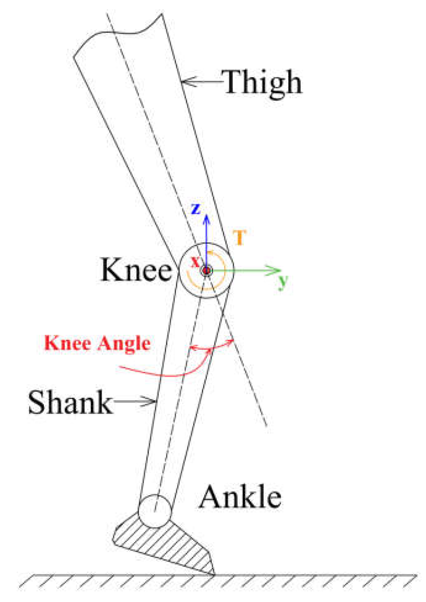
2.1. Characteristics of Knee and Hip Angles

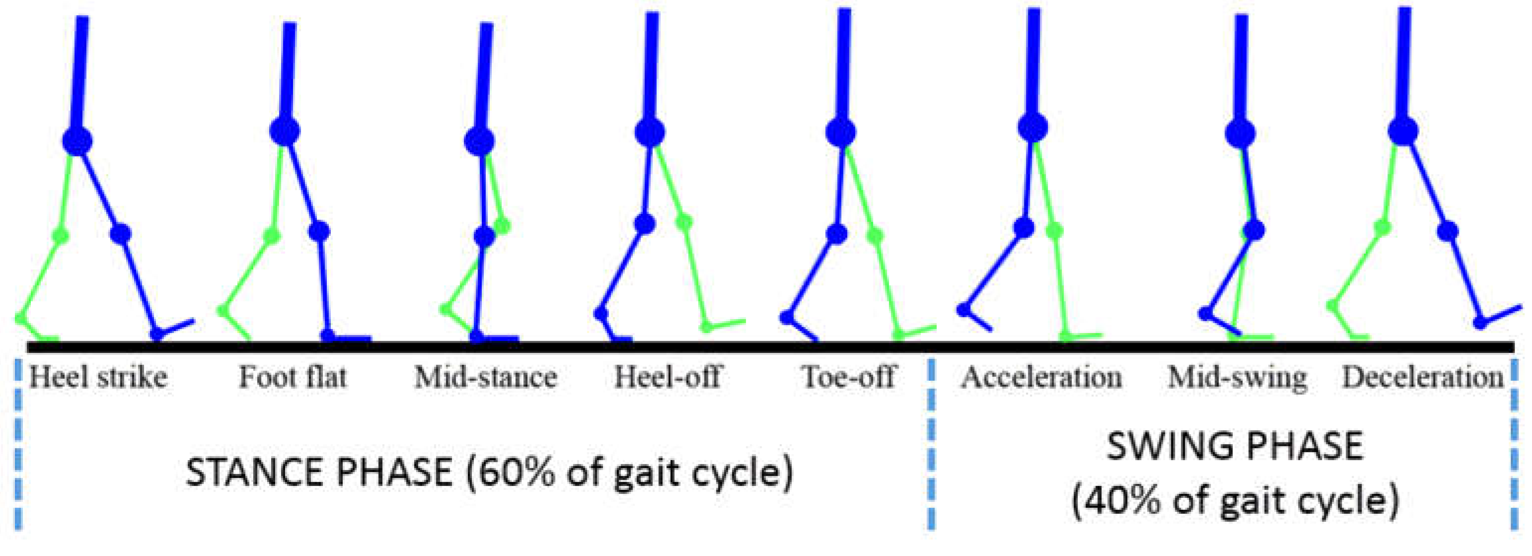
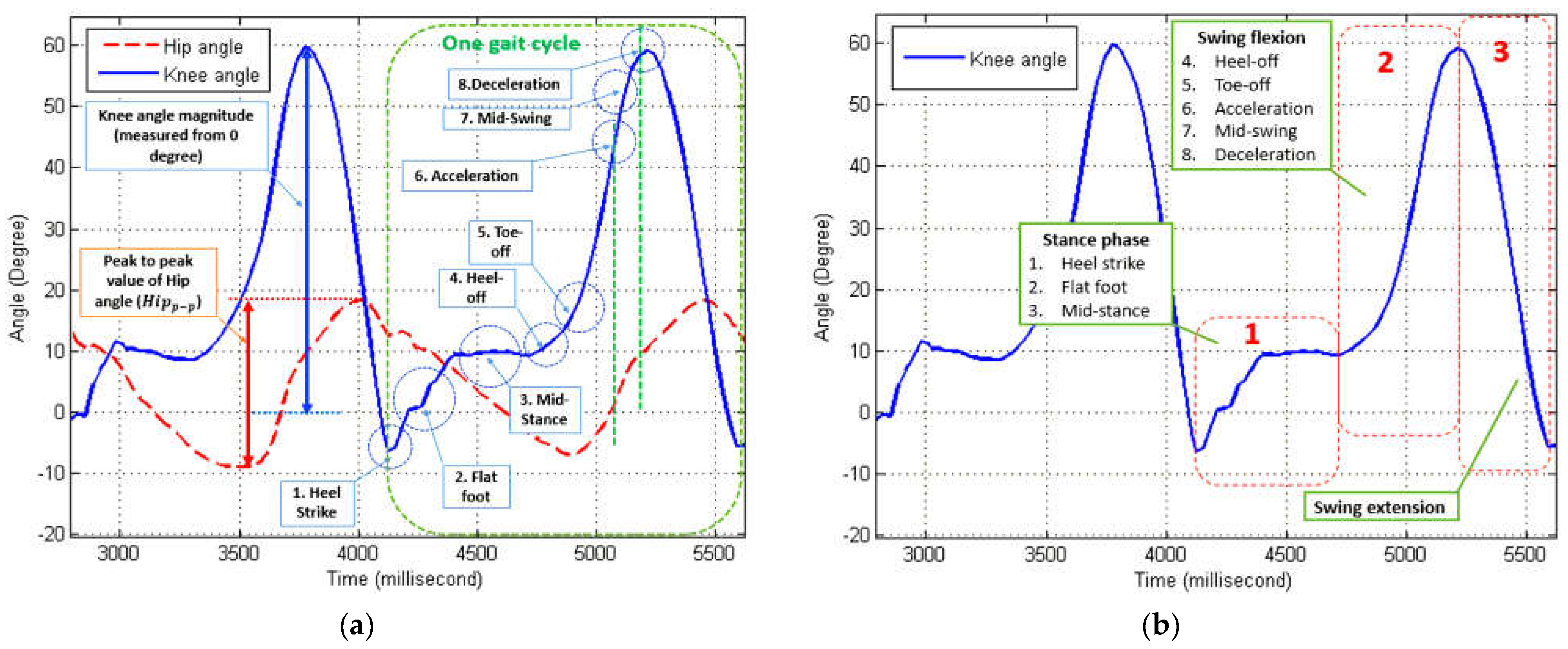
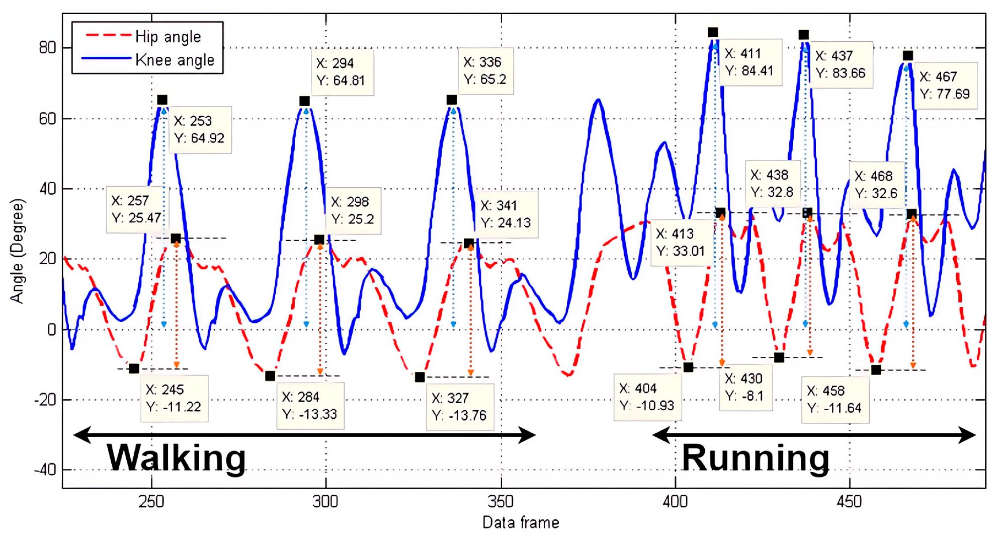
2.1.1. Knee Angle Characteristics of Normal Walking

In this paper, since the hip angle is the primary input of our system to generate the knee angle, it is essential to comprehend the characteristics of the hip angle during a normal walking cycle. Generally, the patterns of hip angle during normal walking are similar, and only the amplitude and the frequency are slightly different in each person [31]. The walking gait cycle involves two main phases: the stance phase (60% of the gait cycle) and the swing phase (40% of the gait cycle) [32]. The leg posture of each event during a gait cycle is shown in Figure 2.
The walking gait cycle has traditionally been divided into eight events or periods [33]. Five events occur during the stance phase, and three events occur during the swing phase. The stance phase events are heel strike, foot-flat, mid-stance, heel-off, and toe-off. It is noted that the push off indicated in Figure 2 represents a combination of the heel-off and toe-off events. The swing phase events are early swing (or acceleration), mid-swing, and late swing (or deceleration). According to [34], the resultant force experienced by the hip joint depends on an individual’s body weight and muscle strength. During the act of walking, this force has been estimated to be approximately three times the individual’s body weight. The highest magnitude of force occurs when the foot is flat on the ground, while the force is at its minimum during the swing phase.
To investigate the eight gait events for identification, the hip and knee angles of normal walking gaits collected from able-bodied subjects were experimentally arranged. Two walking cycles were investigated, as shown in Figure 3a, with each gait event corresponding to the data in Figure 2 labeled with a blue circle, starting from number 1 to number 8. The identification was performed heuristically during normal walking to find the related angle relationships shown in the graph. The main aim of the proposed algorithm is to generate a proper knee angle value based on the hip angle value. In this paper, the knee angle pattern sequences are divided into essential parts to ease the construction of our algorithm. Then, a comprehensive exploration of the role in each part is performed. Finally, an appropriate and feasible algorithm is constructed to generate the knee angle. Therefore, this study divides the knee angle pattern into three main parts, as shown in Figure 3b, including stance, swing flexion, and swing extension phases.
Based on this categorization, the target knee angle can be divided into two essential sections: the maximum straight when the knee angle is 0 degrees and the maximum swing angle. During the stance phase, angle variations are found in the knee angle pattern. The angle variation is due to the heel strike phase, the transition from single-support to double-support, and the mid-stance phase when the entire body mass rests on the stepping leg. Since external factors cause the angle variation, our system does not need to calculate or produce such an angle variation. Consequently, the proposed system only needs to give the default angle for the stance phase. The maximum swing angle needs to be calculated by the walking speed.
Along with the change in the walking speed and the maximum swing angle, the speed of the actuator could be adjusted to achieve an appropriate gait phase at the right time. However, in the proposed system, the instruction to perform the swing flexion phase begins at the heel-off phase, and it occurs two phases earlier than the swing phase during normal walking, as mentioned previously. The reason is that when the prosthesis shank moves from a stationary position and the direction of motion against gravity, there will be a delay of several milliseconds during the acceleration time of the actuator. Therefore, if the swing flexion instruction is given at the toe-off phase, the lagging swing phase will be longer, and the prosthesis movement will not be appropriate.
Another important aspect is determining when to give the target knee angle instructions.
From Figure 4, the heel-off phase begins when the following conditions are satisfied: (1) hip angle is decelerating; (2) thigh direction is swinging backward; and (3) hip angle is smaller than 0°. In addition, the swing extension phase begins if the following conditions occur: (1) hip angle is decelerating; (2) thigh direction is swinging forward; and (3) hip angle is greater than 0°.
Based on the previous descriptions, a finite-state machine (FSM) representing the conditions could be desirable. Therefore, a threshold is added to divide the thigh position into two parts: the front and rear. This threshold value is set initially to be smaller than 0° to prevent reading errors of the deceleration conditions. The reason is that one’s thigh can generally still move a few degrees greater or less than 0° while standing or at the stance phase. The proposed finite-state machine (FSM) diagram is shown in Figure 5.

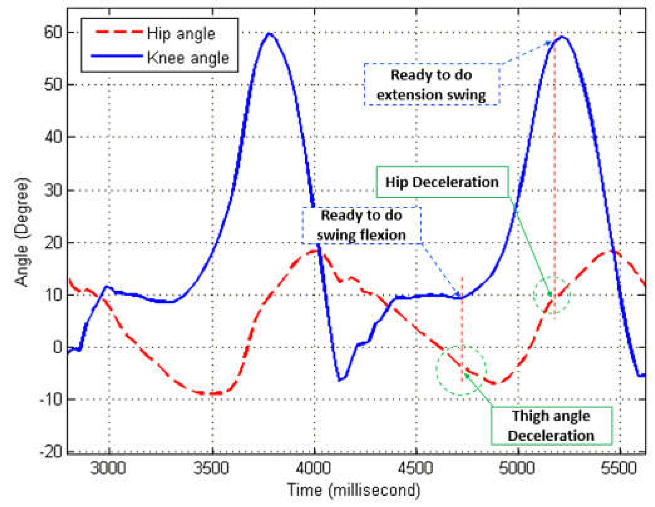
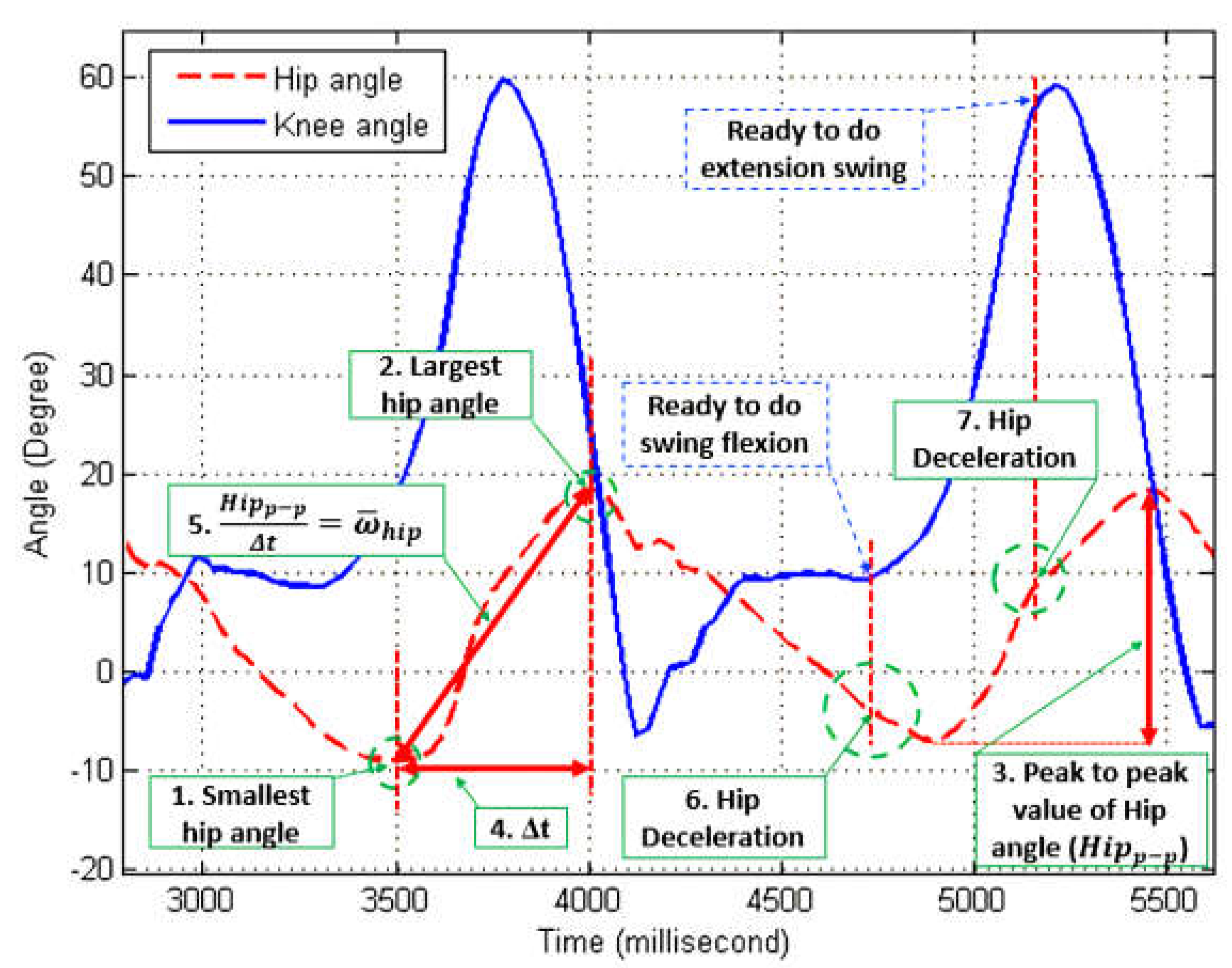
2.1.2. Hip Angle Features According to Walking Phases

Based on the FSM, the essential features of the hip angle could be extracted for the target knee angle and the actuator speed limit calculation. The definitions of hip and knee angles are illustrated in the left part of Figure 6. In addition, the positions of the markers for the motion-capturing system are mounted on the hip, knee, and ankle joints of the subject’s right leg and the prosthetic leg, as shown in the middle and right parts of Figure 6. Therefore, there are seven essential features to be extracted from the hip angle, as illustrated in Figure 7:
1.
Smallest hip angle;
2.
Largest hip angle;
3.
The peak-to-peak value of the hip angle ( H i p p p );
4.
Gait period ( Δ t );
5.
Average angular velocity of the hip swing ( ω ¯ h i p );
6.
The starting point of deceleration in the backward direction;
7.
The starting point of deceleration in the forward direction.
The smallest and the largest hip angle features are used to calculate the hip’s peak-to-peak value ( H i p p p ). The other feature is the angular velocity or ω ¯ h i p of the hip angle during the swing forward, which is essential to find the speed limit for the actuator. This feature is affected by the Δ t value and H i p p p value. The primary purpose of setting this speed limit value is to consider the actuator’s PID control for practical considerations. By giving a limit value for the maximum speed of the actuator, the speed of the actuator will not surpass the limit value. This limit speed value will always be the initial speed for the actuator when the target knee angle changes. The speed value will then change until the accumulated speed that results from each PID gain is smaller than the limit speed value. Finally, starting points of backward hip deceleration and forward hip deceleration are shown as Features 6 and 7. The backward hip deceleration feature represents deceleration when the thigh direction is swinging backward, while the forward hip deceleration feature represents deceleration when the thigh direction is swinging forward, as mentioned previously. These features indicate the beginning of the swing flexion phase and the swing extension phase. The timing of performing the swing phase is needed to make foot clearance during the swing phase, and such foot clearance is also a vital factor in the swing phase to prevent stumbling [35].
The H i p p p value is also used to calculate the target knee angle ( A k n e e ). This consideration is based on the observation that when the walking speed increases, the knee angle amplitude and the hip’s peak-to-peak value also increase. Thus, the ratio between the knee angle amplitude and the hip peak-to-peak value in both walking and running patterns is similar, as shown in Figure 8 and Table 1. In detail, Table 1 shows that the ratio values during walking and running are close, and the empirical ratio is approximately 1.82, which is the average ratio of the sample data. Consequently, this value can be further used to calculate the target knee angle or the amplitude knee value.

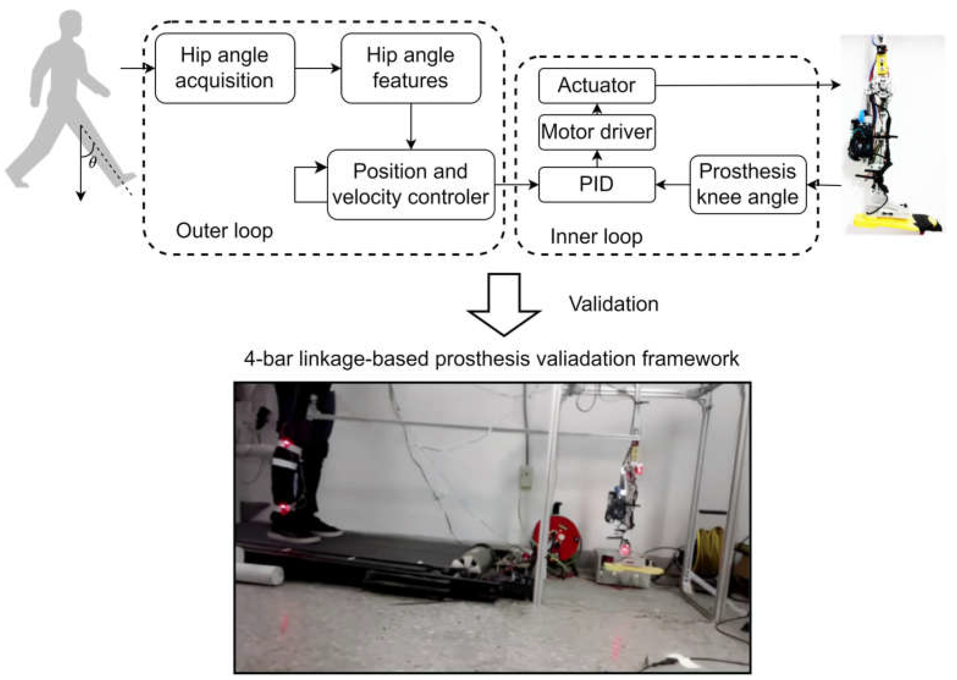
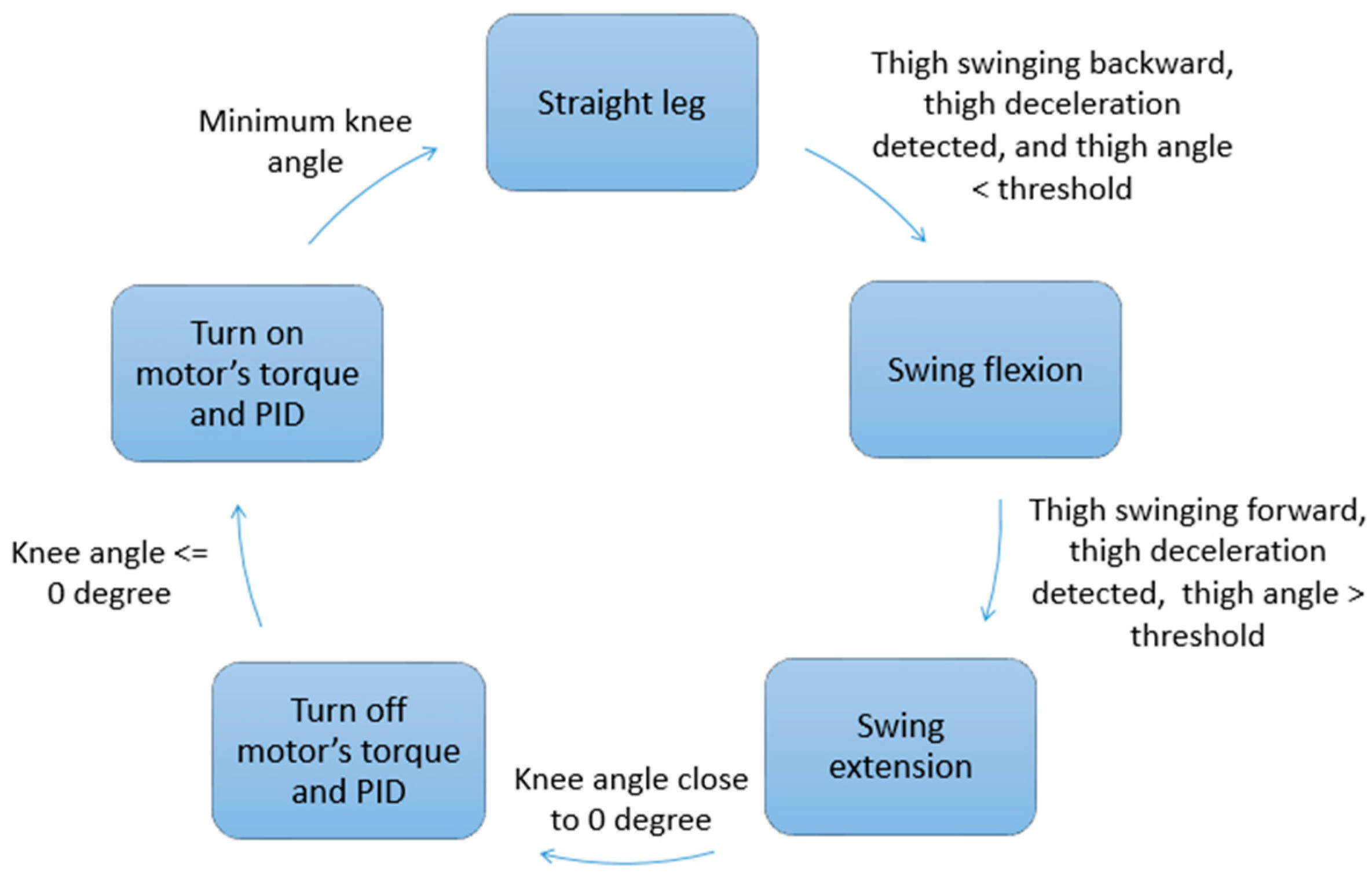
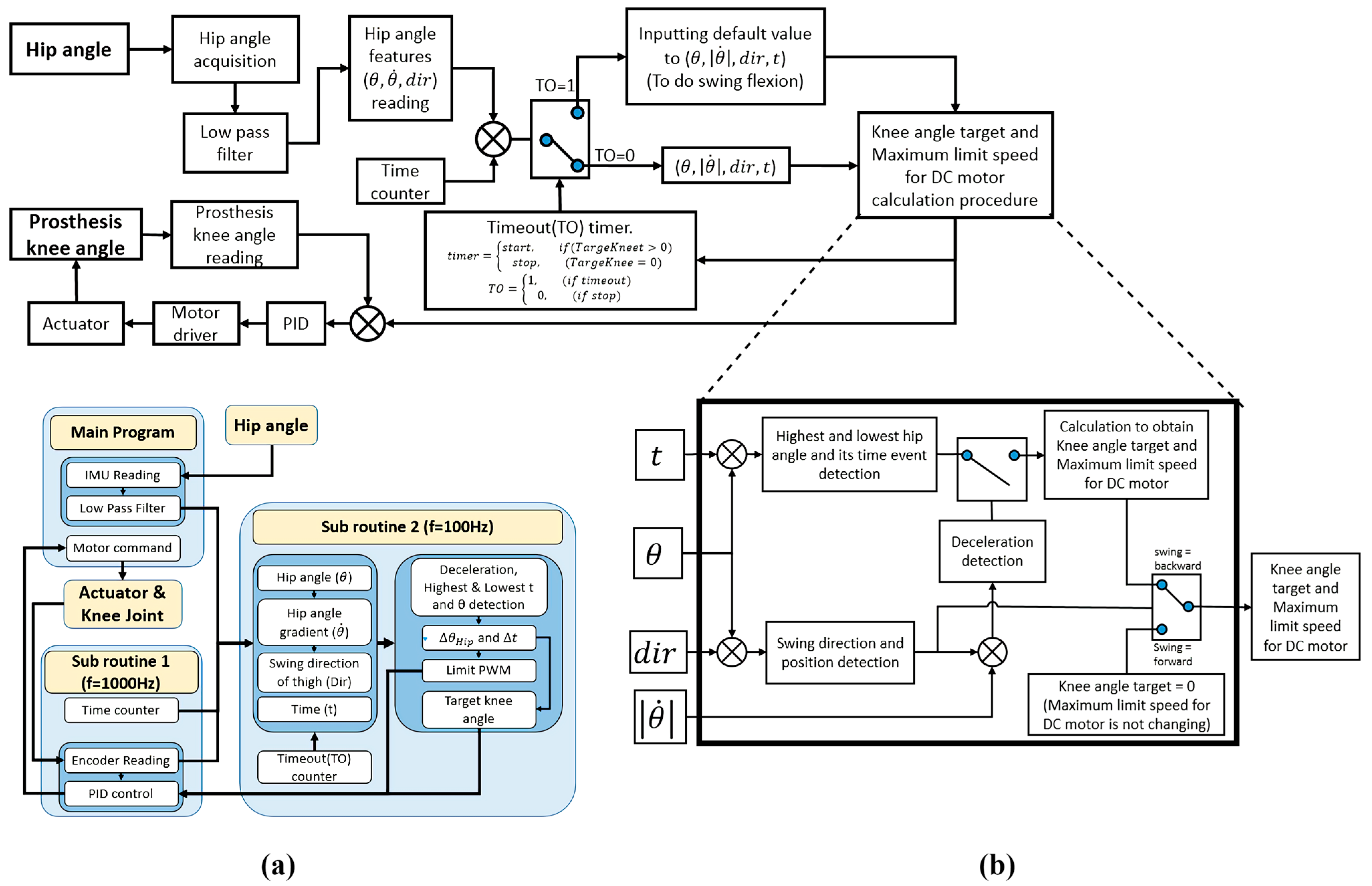
2.2. Knee Angle Generation and Prosthetic Control

2.2.1. Knee Angle Amplitude and Actuator Speed Limit

By knowing the ratio between the hip’s peak-to-peak value and knee amplitude value, this ratio value can be used as a parameter with a constant value to calculate the target knee angle. To ease the use of the calculated ratio parameter, the ratio value is named as C A k n e e constant in this study. Since an individual’s physical posture and walking habits are different, the ratio between the hip’s peak-to-peak and knee angle amplitude of each person could be different. Thus, the C A k n e e value could be adjusted to obtain the best fit for the walking gait habit of the user.
The target knee angle A k n e e can be calculated by multiplying the hip’s peak-to-peak value ( H i p p p ) with the C A k n e e value, as expressed by the following:
A k n e e = H i p p p × C A k n e e
To calculate the speed limit for the actuator, it is necessary to know the correlation between the given motor’s PWM value of the brushless DC motor as well as the angular velocity of the hip swing ( ω ¯ h i p ). To obtain the required PWM to actuate the knee angle from a straight position to the maximum swing flexion angle, several pieces of information, such as the maximum angular velocity value of the brushless DC motor, the total gear reduction ratio, the lead value of the ball screw, and the kinematics of the prosthesis, must be known. For example, the required PWM value to actuate a knee angle from 0 to 60° in 400 ms is 135 in a 255 PWM range value. The ω ¯ h i p value of the hip swing in the same gait cycle is 4.4 deg/0.1 s. Then, the correlation value is the ratio between the required PWM value and the ω ¯ h i p value, and the result can be used as a parameter with a constant value to calculate the speed limit for the actuator. This parameter is called C M l i m , which is expressed as follows:
C M l i m = P W M ω ¯ h i p
If the C M l i m value is known, the maximum limit speed ( M l i m ) of the actuator can be calculated as follows:
M l i m = ω ¯ h i p × C M l i m
Since this value is set as the PWM value for a practical motor driver, the minimum and maximum values cannot surpass the system’s minimum and maximum PWM values. In this system, the maximum PWM value is 255; thus, if the M l i m value is greater than 255, the value of M l i m will be set as 255.

2.2.2. Whole Process Integration

The proposed system is shown in Figure 9, consisting of (a) the software architecture and (b) the system block diagram. For the software architecture, two subroutines are implemented. The first subroutine executes at a high frequency (1 kHz), and it deals with the data collection of hip angle (via an IMU) and knee angle (via an encoder) as well as the PID knee actuator (via a DC brushless motor) control. The second subroutine is executed at a frequency of 100 Hz, and it addresses the knee angle generation and speed limitations. Two subroutines collect sensor data and generate knee angle control commands. A timeout timer is desired to prevent the prosthesis from staying in a swing flexion position if the user stops their thigh movement in the swing flexion position. If this occurs, the timeout timer can send the parameter values, resulting in the desired knee angle of 0°; hence, the prosthesis will be straightened. Moreover, when the target knee angle and speed limit value have been determined, the next step is deploying those values to the PID controller as the information to actuate the knee angle, as indicated in the first subroutine. The following describes the details of generating the target knee angle and the maximum speed limit for the DC motor, as indicated in (4) to (6).
d e c e l = { 1 ,     θ ¨ h i p < 0 0 ,     θ ¨ h i p T
d e c e l is a variable that indicates the detection status of the deceleration event of the hip angle, θ ¨ h i p is the deceleration of the hip angle, and T is the threshold close to 0.
M l i m = { M l i m ,     ( θ T ) ( d i r = 1 ) ( d e c e l = 1 ) ω ¯ h i p × C M l i m ,     ( θ < T ) ( d i r = 0 ) ( d e c e l = 1 )
A k n e e = { 0 ,     ( θ T ) ( d i r = 1 ) ( d e c e l = 1 ) C A k n e e × H i p p p ,     ( θ < T ) ( d i r = 0 ) ( d e c e l = 1 )
d i r represents the swing direction of the thigh; its value will be 0 if the thigh is backward swinging and 1 for forward swinging. Such an operation follows the system block diagram shown in Figure 9b.

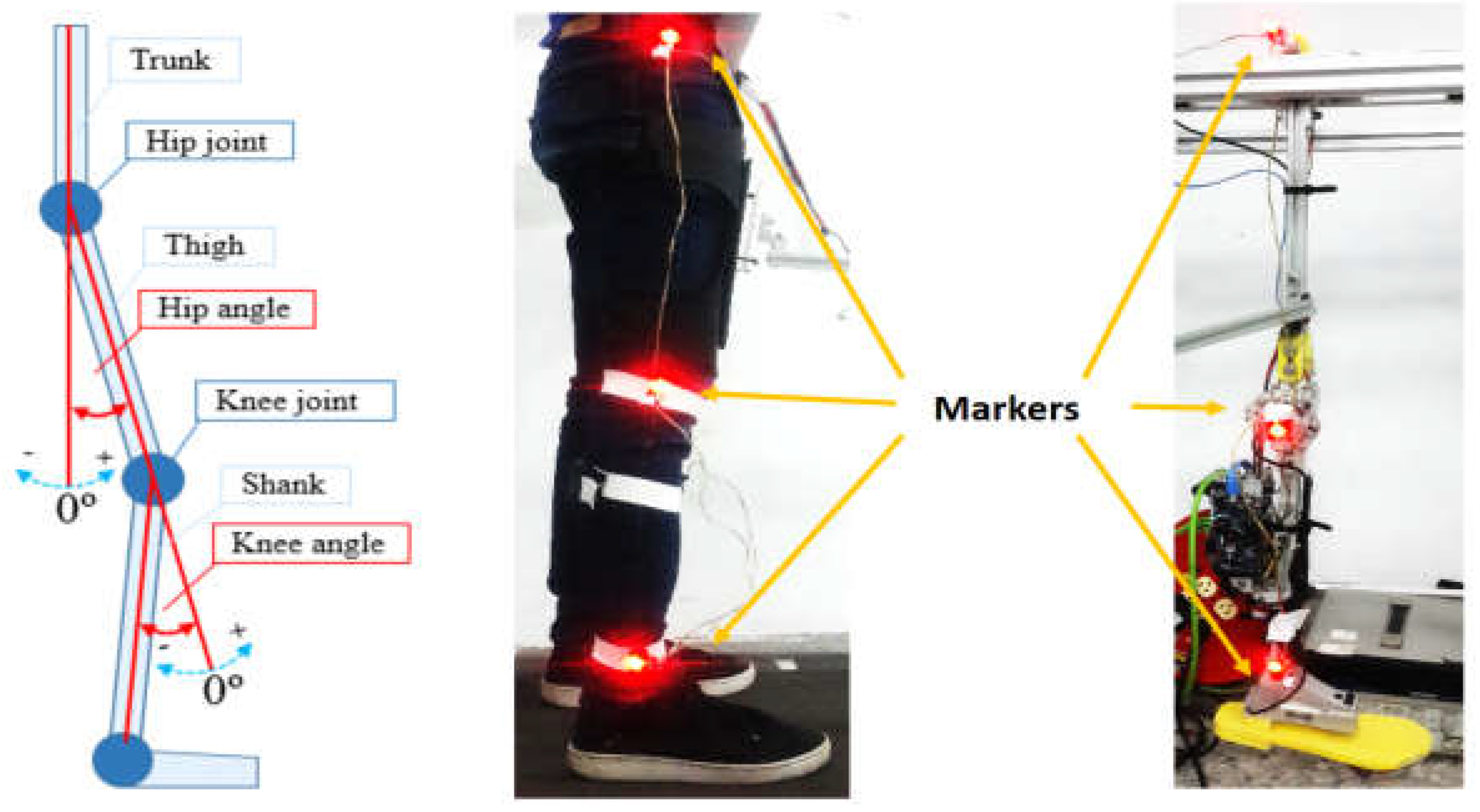
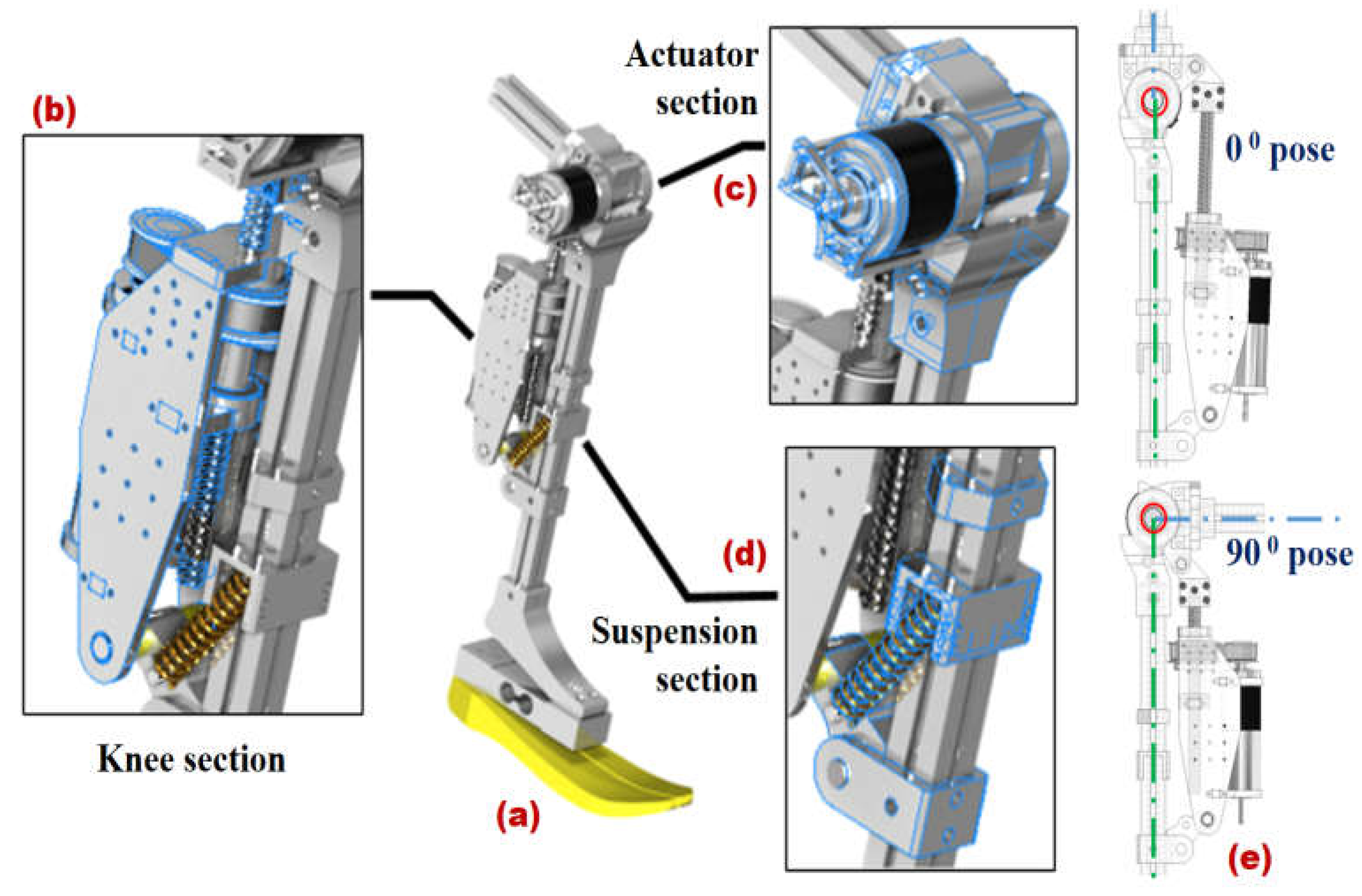
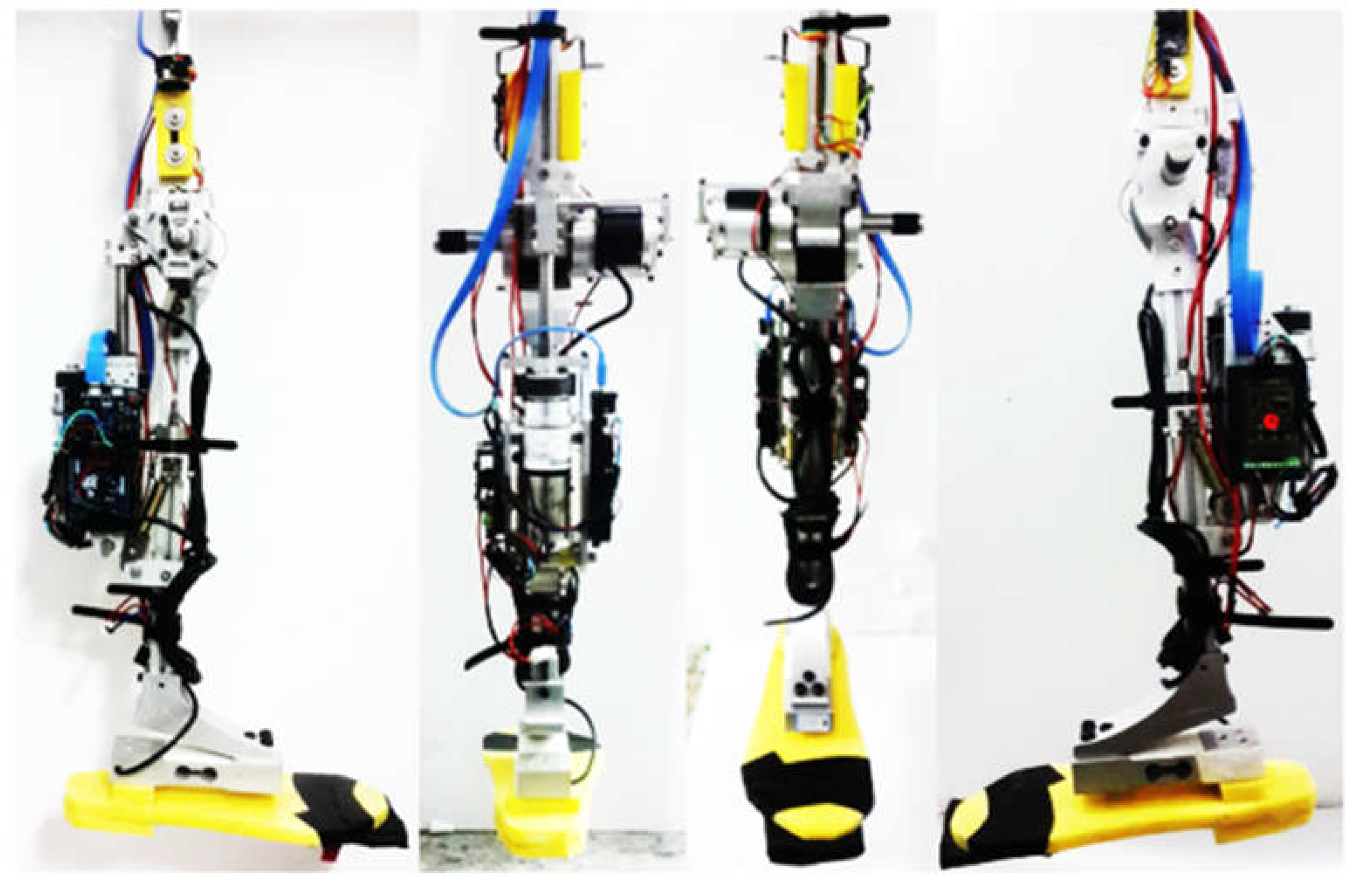
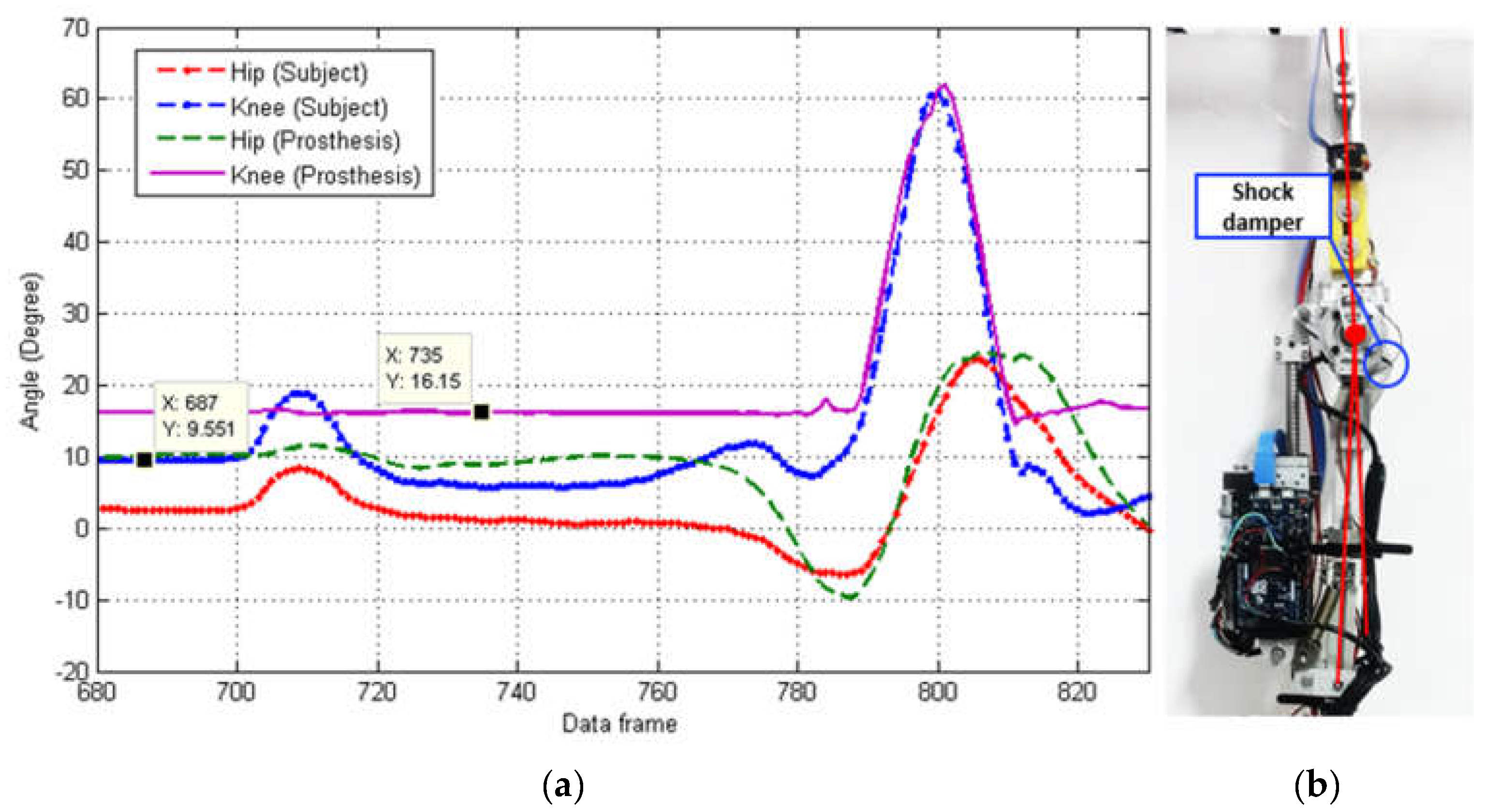
2.2.3. Design of the Prosthetic Leg Prototype

Although prosthetic gait model classification and self-adaption are the major research topics, a physical transfemoral prosthesis prototype is still necessary for practical validation. Hence, this work designed and fabricated a 4-bar linkage artificial knee mechanism driven by a DC brushless motor and a ball screw with a 15 mm pitch. The combination of a gearbox and timing pulley was used to increase the torque of the motor with a reduction ratio of 1:22.4. The overall mechanical structure of the prosthesis consists of three main sections: the knee section, the actuator section, and the suspension section. The knee section consists of a knee joint, an absolute encoder, a thigh-to-knee connector, a shank-to-knee connector, and a lever arm for connecting the ball screw. The knee part is designed to perform knee angles ranging from 0° (straight posture) to 90°. The rotor of the absolute encoder (12-bit data output resolution) should be the same angle as the knee joint angle. The actuator section consists of a Maxon motor with a gearbox and ball screw (Maxon EC-4pole/309757/320247) which is able to run longer at higher power values without overheating; a Maxon motor control 1-Q-EC amplifier DEC module 50/5 (380200) is able to drive EC-motor with power up to 250 W and a maximum speed of 1 pole pair EC-motor up to 80,000 rpm and a timing pulley. The suspension section consists of extension springs, lever arms for connecting springs, and spring extension tuners. Most of the parts for the mechanical structure of the prosthesis are made of aluminum alloy, where the mass and length of the powered transfemoral prosthetic leg are 3 kg and 350 mm, respectively. The design details can be seen in Figure 10. Since the prosthetic prototype is attached to amputee’s thigh using a bypass, the actuator section of the prosthetic is used to generate a target knee angle when amputee starts moving. Thus, the proposed prosthetic prototype has 1 degree of freedom (DOF) in X-axis, as illustrated in Figure 11.
An IMU sensor (MPU6050) should be mounted on the top of the knee part to read the hip angle of the prosthesis. The IMU sensor data is the information used to generate the target knee angle. The knee angle is obtained via an absolute encoder mounted on the knee joint. The primary design theme is to produce a real-time (100 Hz in this study); hence, each sensor data point is individually processed by a slave microcontroller to reduce the processing burden of the main microcontroller so that the response and processing time of the prosthesis can be faster and more efficient. The acquired sensor values will then be sent to the main microcontroller through serial communication. The main tasks of the main microcontroller are signal processing, target knee angle calculations, and actuator control. The main microcontroller uses a 32-bit Arduino with an 84 MHz processing speed.
The prosthesis control scheme uses a three-interrelated-level control architecture, including low-level, mid-level, and high-level controllers. In the low-level controller, the combination of the PID control and the feedback knee angle from the absolute encoder is used to control the knee angle toward the calculated target knee angle. In the mid-level controller, a finite-state machine (FSM) determines the timing to activate the stance, swing-flexion, and swing-extension phases and evokes the PID control system. Finally, in the high-level controller, the target knee angle and speed of the gait are generated. The algorithms for this controller’s level are the core focus of this paper, and the details are elaborated on in the following sections. The final mechatronic integrated fabrication with the deployments of sensors and microcontrollers is shown in Figure 12.

3. Results and Discussion

3.1. Experimental Setup

To validate the natural walking gait simulation from hip angle data, the experiment will be assisted by a mechanical thigh connected to a rigid aluminum frame by a 1 DoF (Degree of Freedom) revolute joint in the X-axis. The thigh motion of the prosthesis leg will be controlled by an able-bodied subject walking on a treadmill. The able-bodied subject’s thigh motion will be transferred to the mechanical thigh of the prosthesis rough an aluminum bar. The connections of the aluminum bar are 2 DoF for rotation in Z-axis and X-axis; thus, only the motion in the Y-axis direction will be transferred to the mechanical thigh. The prosthesis’s electronic connection and sensor alignment also needs to be appropriately set. The environment setup for the experiment is shown in Figure 13.
The experiment involves 5 able-bodied subjects, including young males and females from 21- to 27-year-olds, whose body height ranges from 160 to 185 cm and weight ranges from 50 to 80 kg, with 172.67 cm and 62.91 kg on average and 1.498 cm and 5.418 kg in standard deviation, respectively. The biometric information of experimental subjects can be found in Table 2.
According to Section 2.2.1, there are two critical parameters that need to be set for the prosthesis leg: knee amplitude gain C A k n e e and motor limit value C M l i m . To establish a proper value for each parameter, it is necessary to know the walking characteristics of able-bodied subjects. Hence, motion data acquisition, as shown in Figure 14, is required to find the best value parameters. IMU sensors are placed on the link of the target limb. The microcontrollers will receive the angle data from IMU and then send it to PC. In this experiment, Matlab software was used to process the angle data and obtain the joint angle of the target limb ( A k n e e ):
A k n e e = θ x 1 θ x 2
Then, the estimated C A k n e e and C M l i m can be obtained by Equations (1) and (2). For C A k n e e value, it is acceptable if it has a small difference between the theoretical value and actual values, as long as the main purpose of the knee motion during walking has been fulfilled. The C A k n e e value may differ for each person, even when performing at the same walking speed, because of the person’s physical posture and walking habits. Therefore, to verify our proposed methods, we chose able-bodied subjects with similar walking behaviors in similar biometric information, as described in Table 2. In this paper, we select the C A k n e e is 1.8.
Moreover, according to the proposed finite state machine of the prosthesis in Section 2.1, to determine the interchanging moment between the stance phase (straight leg) and swinging phases, a threshold is defined iteratively. In particular, the threshold value is required to be less than the peak-to-peak value of the hip angle ( H i p p p ), i.e., around half of H i p p p , and will be updated in every step cycle. The current threshold value will be applied to the knee angle calculation for the next walking cycle.

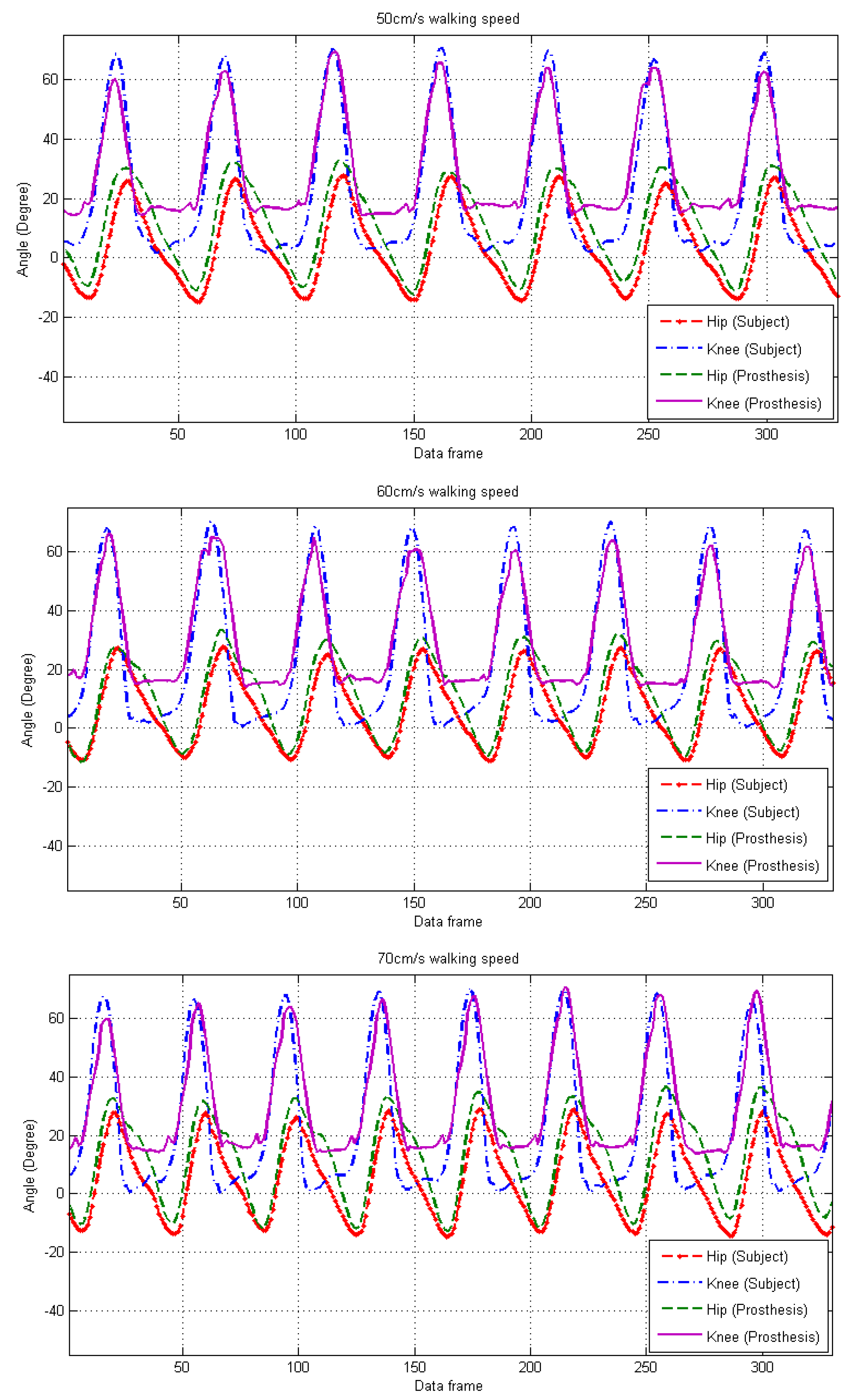
3.2. Experimental Results without Using a Bypass Adapter

For the first experiment, we are going to validate that the actuated prosthetic knee pattern can follow the subject’s knee pattern well. It is challenging for most researchers because it is difficult to obtain the ground of the prosthetic knee pattern when the experiments are applied to a healthy subject wearing a bypass adaptor or to an amputee wearing a prosthetic socket. Our paper proposes a four-bar linkage measurement solution. The construction of the four-bar linkage mechanism connecting an able-bodied subject and a distal prosthetic leg module is able to quantitatively evaluate the synchronization and trajectory tracking between the subject’s knee angle and the prosthetic knee angle with a motion capture system. Hence, the experiment constructed with a four-bar linkage mechanism configuration provided strong evidence of the knee angle following and synchronization performance based on confident knee pattern ground truth.
The preliminary experiments were conducted by an able-bodied subject walking on a powered treadmill. A parallel four-bar linkage was constructed for master–slave operation. During the experiment, the prosthesis was hung on a mechanical thigh with one degree of freedom to revolute the joint at the hip joint, as shown in the top part of Figure 15. The parallel four-bar linkage connects the subject’s thigh limb and the upper link of the powered transfemoral prosthetic leg module so that the pose of the subject’s thigh limb would be the same as that of the upper link of the powered transfemoral prosthetic leg module. Such an experimental setup is convenient and helpful for validating the synchronization of knee angle generation and control of the powered transfemoral prosthetic leg module without using any bypass adapter dressing on the able-bodied subjects.
Validation of the transfemoral prosthetic leg’s knee angle motion can be performed by comparing the able-bodied subject’s knee angle trajectory via a conventional motion capture system PhaseSpace System, powered by PhaseSpace Inc., San Leandro, CA, USA. Six LED trackers were mounted on the subject’s lower limb and the transfemoral prosthetic leg to dynamically calculate the synchronization of the subject and transfemoral prosthetic leg knee angles.
The experimental protocol is as follows. The subject connects his thigh limb to the parallel four-bar linkage to form a mechanical master–slave operational mechanism. Hence, the thigh motion of the prosthetic leg will be controlled by the distal able-bodied subject walking on a treadmill. The subject’s thigh motion will then be transferred to the mechanical thigh of the prosthesis through an aluminum bar. The treadmill’s speed is controlled by a microcontroller using a PID control scheme; thus, the treadmill’s speed could be stable for validation. This experiment was programmed to have 3 levels of speed: 50 cm/s, 60 cm/s, and 70 cm/s. The speed of the treadmill was changed manually, but no resetting parameter values of the prosthesis were needed for the different walking speeds. The performance of the prosthesis was evaluated using the aforementioned motion capture system. The root mean squared error (RMSE) was evaluated between the subject knee angle and the prosthetic knee angle. The video for this experiment can be found at https://youtu.be/1nBAY_vKAwI (accessed on 3 November 2022).

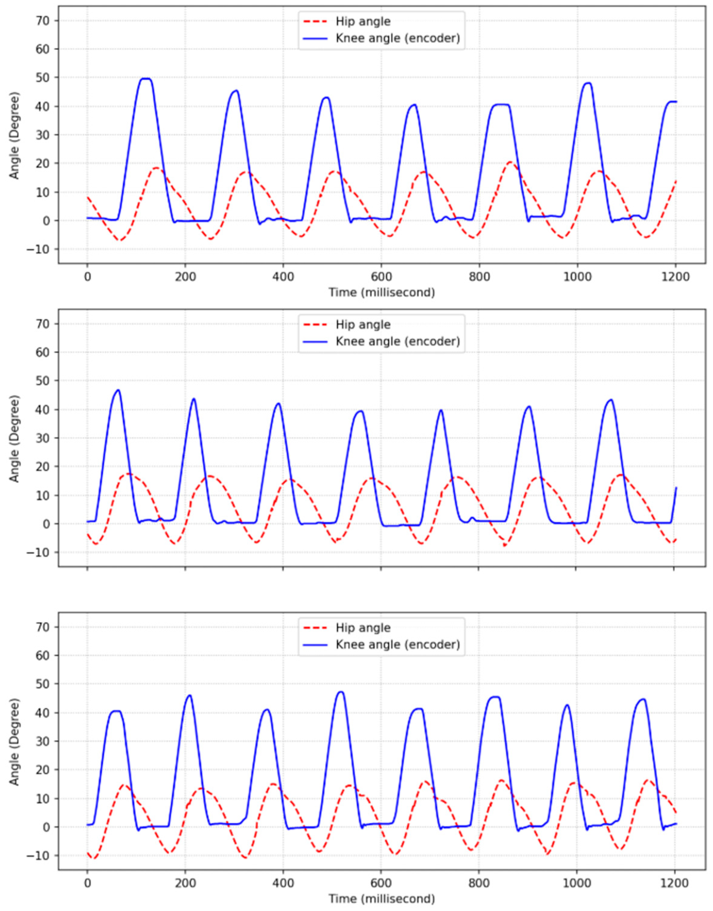
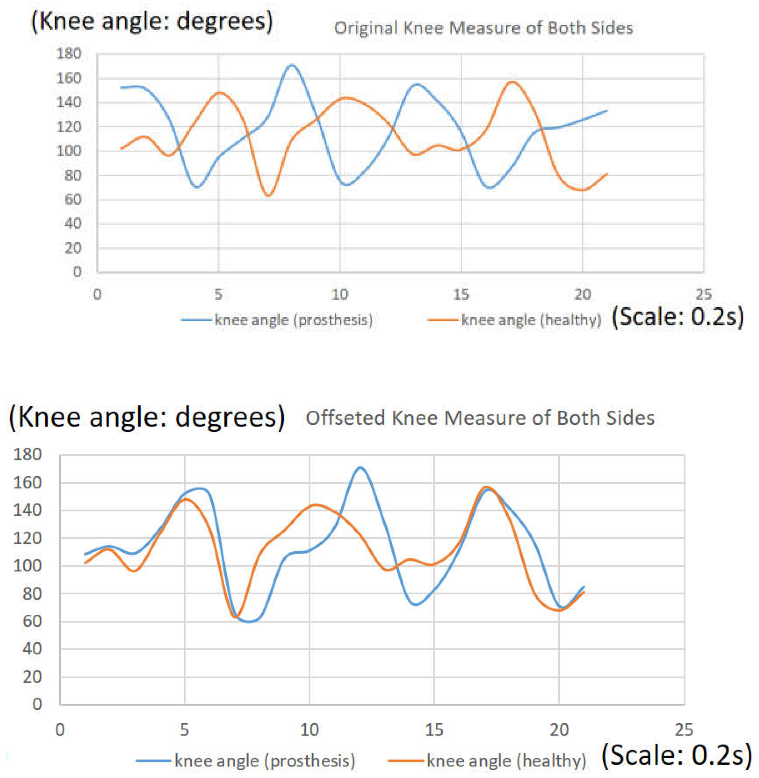
3.3. Treadmill and Real-Taking Experiment Using a Bypass Adapter

Although the four-bar linkage configuration experiment provided a confident ground comparison for the actuated knee angle, real walking with a bypass adaptor is still necessary to know the actual walking performance from the investigation of walking. Hence, two bypass adaptor walking experiments are arranged on both treadmill and in-doorway experiments. To examine the performance of wearing the powered transfemoral prosthetic leg for able-bodied subjects, a bypass adapter was produced along with a transfemoral prosthetic leg for real walking validation and then was worn on the right leg of the experiment subject. The validations were performed by walking on a treadmill and in a corridor. The time-lapse captured video of the bypass adapter prosthesis walking experiment on a treadmill, as shown in Figure 16, was recorded via a video available at https://youtu.be/4QpOG4WMoXg (accessed on 3 November 2022).
Another natural walking experiment was conducted in a corridor. The able-bodied subject wore a transfemoral prosthetic leg with a bypass adapter and walked at non-specified speeds. Hence, this experiment investigated the transfemoral prosthetic leg’s knee angle generation and speed adaptation in a real walking scenario. The time-lapse captured video of the bypass adapter prosthesis walking experiment in a corridor environment with a total of 20 m walking distance is shown in Figure 17. The experimental process was recorded by video, which is available at https://youtu.be/39bIanPwsIQ (accessed on 3 November 2022).

4. Discussion

4.1. Discussion of Experiment with Four-Bar Linkage Mechanism

This experiment aims to evaluate the performance of the transfemoral prosthetic leg prototype in performing natural walking gait motions based on the hip angle motion input given by the distal subject. The results collected from commercial motion capture system LED trackers were evaluated to simultaneously calculate the hip and knee angles of the subject and the prosthesis. Figure 18 shows the results of 3 different walking speeds of 50 cm/s, 60 cm/s, and 70 cm/s with the same 330 data frames. It is noted that the walking speeds are referred to as 0.55 steps/s, 0.6 steps/s, and 0.65 steps/s, respectively. From these comparison charts, the prosthetic knee angle tracked the subject’s knee angle well, representing RMSEs of 9.9°, 11.3°, and 13.0°, respectively. The results prove that our proposed four-bar linkage mechanism helps the actuated prosthetic knee pattern to follow the able-bodied subject’s knee pattern well on the same side when walking on the treadmill.

4.2. Discussion of RMSE Investigations on Knee Actuator Speed Limitation and the Initial Knee Angle Offset

The knee angle tracking data show that a higher walking speed results in a larger RMSE. Such a phenomenon is mainly due to the performance limitation of the DC brush motor and the ball screw actuators. The combination of a 1:22.4 speed reduction and a 15 mm ball screw pitch limits the maximum speed of the prosthetic knee. In addition, it might be caused by several other factors, such as parameter settings, the initial posture of the prosthesis, and variations in the subject condition. The error induced by the parameter setting is crucial—the calculation to obtain the parameters only considered specific known factors. Nevertheless, practically speaking, many factors could affect the prosthesis’s performance, such as friction on the lead screw, gravity, moment, and inertia during the motion and power supply.
The other factor is the initial posture difference between the subject’s knee and prosthetic knee angles [36]. The initial posture of the prosthesis during the experiment was not straight or at 0°. This was due to the shock damper placed between the knee angle limiter on the knee part, with such a condition illustrated in Figure 19b. This condition caused the initial angle of the knee to become more than 0°, as indicated by the motion capture result shown in Figure 19a. In this figure, the initial knee angle of the prosthesis is approximately 16.15°, and the initial knee angle of the subject is approximately 9.55°; hence, the difference between the knee angle of the prosthesis and the knee angle of the subject is approximately 6.6°. Since this initial knee angle offset is not a system bias parameter, it would not affect the target knee angle calculation. This was why the prosthesis’s maximum swing flexion angle was almost the same as the maximum swing flexion angle of the subject. If this error value roughly subtracts the RMSE value of each walking speed, then the RMSE error could be smaller than 6.6°. Particularly, the calculation of the RMSEs on three separate phases of stance, swing flexion, and swing extension in the abovementioned experiments are also evaluated, as indicated in Table 3. The table discussed the original RMSE value and compensated RMSE with 6.6° to see the tracking performance of actuated prosthetic knee angles. The performance of the swing flexion phase is good, with a maximum RMSE never exceeding 0.27°; the RMSE of the stance phase is relatively consistent, around 4.4° to 5.8°. Nevertheless, the RMSE of the swing extension phase increases with the walking speed, ranging from 1.953° to 13.466°. Because of actuating more significant strokes in a limited time interval, the speed limit of the motor results in significant effects on the actuated tracking performance.

4.3. Discussion of Experiment with Using a Bypass Adapter

We have analyzed the knee angles of the prosthetic side (i.e., wearing a bypass socket side) and healthy limb side (i.e., not wearing a bypass socket side) for comparisons based on the treadmill experiment with wearing a bypass adopter. The purpose is to evaluate the gait similarity of both sides. The knee angles of both sides are measured from the video frames with marked feature points, and some possible label error would be possible. The knee angle definition of labeling in the video is different from Figure 18 and Figure 20. The angle ranges from 160° around (straight) to 80° around (maximum flexion). Such a definition differs from 0° to 60° around addressed in Figure 18, Figure 19 and Figure 20. It is noted that the data shown in this figure are processed by a curve smoothing operation.
Moreover, the evaluation of the gait similarity of both side legs is illustrated in Figure 21. The results with the offset knee angles represent a high degree of similarity of gait patterns of both sides, which shows the Pearson correlation coefficient of 0.6866. With the high similarity of the gait patterns on both sides of the legs, it makes the prosthetic prototype generate the appropriate knee angle at different speed levels, helping amputees use less force during the gait loading stage (the second stage in the stance phase, i.e., Figure 2) [37,38].

4.4. Limitation and Future Work

This study proposes an algorithm regarding the desired knee angle as the multiplication of the peak-to-peak value of the hip angle H i p p p and C A k n e e constant. Although this method ensures an extremely low computational complexity, the constant comes from the average value of the subjects, meaning that the value might not be suitable for every subject. Additionally, the current experiment contains a limited variety of experimental subjects with similar ages and lengths of legs, and the amputees have not been considered in the experiment yet.
For future work, the multiplier may be considered a tunable parameter and can be optimized based on the physical information of the different users of the prosthetic legs. Additionally, the prosthetic legs should be tested on a wider variety of amputees to ensure the actual performance of the natural walking of practical users. Moreover, adopting computational simulation [39,40] in improving prosthesis legs should be the potential further study since it brings several benefits, such as giving low-cost and rapid results compared to designing experimental tests.

5. Conclusions

This paper investigated the relationship between hip and knee angle trajectories during normal walking to form an algorithm that can dynamically generate natural walking gait patterns. In the lightweight microprocessor-control prosthetic leg prototype, we proposed to use a simple IMU to obtain the hip angle and an absolute encoder to obtain the current prosthetic knee angle as inputs for calculation. This study evaluated the overall prosthetic control system’s performance using an adjustable-speed treadmill with a master–slave validation configuration. Such a master–slave validation configuration can be obtained by directly driving the thigh part of the prosthetic through a parallel four-bar linkage mechanism to synchronize with the able-bodied subject’s motion. At the walking speeds of 50 cm/s, 60 cm/s, and 70 cm/s, the RMSE values of prosthetic knee angle tracking are 9.9°, 11.3°, and 13.0°, respectively. However, the fabricated powered transfemoral prosthetic leg is a prototype used only for validation, and a higher walking speed results in a larger RMSE due to the saturation phenomenon resulting from the combination of a 1:22.4 speed reduction and a 15 mm ball screw pitch that limits the maximum speed of the prosthetic knee. Therefore, a revised powered prosthesis could be designed and fabricated in future work to improve the knee angle tracking performance. The initial knee angle difference (i.e., initial offset) could be given consideration to further reduce the RMSE during a small knee angle operation range. Moreover, implementing computational simulation for improving prosthesis legs could be a potential future work since its benefits compared to designing experimental tests.

Author Contributions

Conceptualization, I.W.D.P. and C.-H.K.; methodology, I.W.D.P., K.-H.S. and C.-H.K.; writing—original draft preparation, I.W.D.P.; writing—review and editing, I.W.D.P., P.T.-T.N. and C.-H.K.; visualization, I.W.D.P. and P.T.-T.N.; supervision, C.-H.K.; project administration, C.-H.K.; funding acquisition, Y.-C.K. and C.-H.K. All authors have read and agreed to the published version of the manuscript.

Funding

This work was finically supported by the Ministry of Science and Technology, Taiwan, ROC under Grant MOST 109-2221-E-011-136-MY3 and the “Center for Cyber-physical System Innovation” from The Featured Areas Research Center Program within the framework of the Higher Education Sprout Project by the Ministry of Education (MOE) in Taiwan.

Data Availability Statement

Not applicable.

Conflicts of Interest

The authors declare no conflict of interest.

References

  1. Lee, W.T.; Russell, K.; Sodhi, R.S. On Transfemoral Prosthetic Knee Design for Natural Human Knee Motion. Recent Pat. Mech. Eng. 2020, 13, 49–59. [Google Scholar] [CrossRef]
  2. Au, S.K.; Weber, J.; Herr, H. Powered Ankle-Foot Prosthesis Improves Walking Metabolic Economy. IEEE Trans. Robot. 2009, 25, 51–66. [Google Scholar] [CrossRef]
  3. Gregg, R.D.; Lenzi, T.; Hargrove, L.J.; Sensinger, J.W. Virtual Constraint Control of a Powered Prosthetic Leg: From Simulation to Experiments with Transfemoral Amputees. IEEE Trans. Robot. 2014, 30, 1455–1471. [Google Scholar] [CrossRef] [PubMed]
  4. Fluit, R.; Prinsen, E.C.; Wang, S.; van der Kooij, H. A Comparison of Control Strategies in Commercial and Research Knee Prostheses. IEEE Trans. Biomed. Eng. 2020, 67, 277–290. [Google Scholar] [CrossRef] [PubMed]
  5. Yu, T.; Plummer, A.R.; Iravani, P.; Bhatti, J.; Zahedi, S.; Moser, D. The Design, Control, and Testing of an Integrated Electrohydrostatic Powered Ankle Prosthesis. IEEE/ASME Trans. Mechatron. 2019, 24, 1011–1022. [Google Scholar] [CrossRef]
  6. Zhu, J.; Jiao, C.; Dominguez, I.; Yu, S.; Su, H. Design and Back-drivability Modeling of a Portable High Torque Robotic Knee Prosthesis with Intrinsic Compliance for Agile Activities. IEEE/ASME Trans. Mechatron. 2022, 27, 1837–1845. [Google Scholar] [CrossRef] [PubMed]
  7. Rouse, E.J.; Mooney, L.M.; Herr, H.M. Clutchable Series-elastic Actuator: Implications for Prosthetic Knee Design. Int. J. Robot. Res. 2014, 33, 1611–1625. [Google Scholar] [CrossRef]
  8. Elery, T.; Rezazadeh, S.; Nesler, C.; Gregg, R.D. Design and Validation of a Powered Knee–Ankle Prosthesis With High-Torque, Low-Impedance Actuators. IEEE Trans. Robot. 2020, 36, 1649–1668. [Google Scholar] [CrossRef]
  9. Hoover, C.D.; Fulk, G.D.; Fite, K.B. The design and initial experimental validation of an active myoelectric transfemoral prosthesis. J. Med. Device 2012, 6, 011005. [Google Scholar] [CrossRef]
  10. Canino, J.M.; Fite, K.B. Haptic feedback in lower-limb prosthesis: Combined haptic feedback and EMG control of a powered prosthesis. In Proceedings of the 2016 IEEE EMBS International Student Conference, Ottawa, ON, Canada, 29–31 May 2016; pp. 1–4. [Google Scholar]
  11. Langlois, D. Reactive Layer Control System for Prosthetic and Orthotic Devices. U.S. Patent 9,808,357 B2, 26 May 2017. [Google Scholar]
  12. Bedard, S. Control Device and System for Controlling an Actuated Prosthesis. U.S. Patent 9,649,206 B2, 16 May 2017. [Google Scholar]
  13. Thatte, N.; Shah, T.; Geyer, H. Robust and Adaptive Lower Limb Prosthesis Stance Control via Extended Kalman Filter-Based Gait Phase Estimation. IEEE Robot. Autom. Lett. 2019, 4, 3129–3136. [Google Scholar] [CrossRef]
  14. Galey, L.; Gonzalez, R.V. Design and Initial Evaluation of a Low-Cost Microprocessor-Controlled Above-Knee Prosthesis: A Case Report of 2 Patients. Prosthesis 2022, 4, 60–72. [Google Scholar] [CrossRef]
  15. Dey, S.; Yoshida, T.; Foerster, R.H.; Ernst, M.; Schmalz, T.; Schilling, A.F. Continuous Prediction of Joint Angular Positions and Moments: A Potential Control Strategy for Active Knee-Ankle Prostheses. IEEE Trans. Med. Robot. Bionics 2020, 2, 347–355. [Google Scholar] [CrossRef]
  16. Skelly, M.M.; Chizeck, H.J. Real-Time Gait Event Detection for Paraplegic FES Walking. IEEE Trans. Neural Syst. Rehabil. Eng. 2001, 9, 59–68. [Google Scholar] [CrossRef] [PubMed]
  17. Lenzi, T.; Hargrove, L.J.; Sensinger, J.W. Preliminary Evaluation of a New Control Approach to Achieve Speed Adaption in Robotic Transfemoral Prostheses. In Proceedings of the International Conference on Intelligent Robots and System (IROS 2014), Chicago, IL, USA, 14–18 September 2014. [Google Scholar]
  18. Mendez, J.; Hood, S.; Gunnel, A.; Lenzi, T. Powered Knee and Ankle Prosthesis with Indirect Volitional Swing Control Enables Level-ground Walking and Crossing Over Obstacles. Sci. Robot. 2020, 5, eaba6635. [Google Scholar] [CrossRef] [PubMed]
  19. Wen, Y.; Li, M.; Si, J.; Huang, H. Wearer-Prosthesis Interaction for Symmetrical Gait: A Study Enabled by Reinforcement Learning Prosthesis Control. IEEE Trans. Neural Syst. Rehabil. Eng. 2020, 28, 904–913. [Google Scholar] [CrossRef]
  20. Tommaso, L.; Hargrove, L.; Sensinger, J. Speed-adaptation mechanism: Robotic prostheses can actively regulate joint torque. IEEE Robot. Autom. Mag. 2014, 21, 94–107. [Google Scholar]
  21. Quintero, D.; Villarreal, D.J.; Lambert, D.J.; Kapp, S.; Gregg, R.D. Continuous-phase control of a powered knee ankle prosthesis: Amputee experiments across speeds and inclines. IEEE Trans. Robot. 2018, 34, 686–701. [Google Scholar] [CrossRef]
  22. Best, T.K.; Embry, K.R.; Rouse, E.J.; Gregg, R.D. Phase-variable control of a powered knee-ankle prosthesis over continuously varying speeds and inclines. In Proceedings of the 2021 IEEE/RSJ International Conference on Intelligent Robots and Systems (IROS), Prague, Czech Republic, 27 September–1 October 2021. [Google Scholar]
  23. Naber, A.; Mastinu, E.; Ortiz-Catalan, M. Stationary Wavelet Processing and Data Imputing in Myoelectric Pattern Recognition on a Low-Cost Embedded System. IEEE Trans. Med. Robot. Bionics 2019, 1, 256–266. [Google Scholar] [CrossRef]
  24. Tran, M.; Gabert, L.; Cempini, M.; Lenzi, T. A Lightweight, Efficient Fully Powered Knee Prosthesis With Actively Variable Transmission. in IEEE Robot. Autom. Lett. 2019, 4, 1186–1193. [Google Scholar] [CrossRef]
  25. Williams, W. A Complete Guide to Binonic Legs & Feet. Available online: https://bionicsforeveryone.com/ (accessed on 17 April 2022).
  26. Musolf, B.M.; Earley, E.J.; Munoz-Novoa, M.; Ortiz-Catalan, M. Analysis and Design of a Bypass Socket for Transradial Amputations. In Proceedings of the 2021 43rd Annual International Conference of the IEEE Engineering in Medicine & Biology Society (EMBC), Virtual Conference, Guadalajara, Mexico, 1–5 November 2021. [Google Scholar]
  27. Öberg, V.; Thesleff, A.; Ortiz-Catalan, M. Design of an open-source transfemoral, bypass socket. In Proceedings of the 2021 43rd Annual International Conference of the IEEE Engineering in Medicine & Biology Society (EMBC), Virtual Conference, Guadalajara, Mexico, 1–5 November 2021. [Google Scholar]
  28. Goldfarb, N.; Lewis, A.; Tacescu, A.; Fischer, G.S. Open source Vicon Toolkit for motion capture and Gait Analysis. Comput. Methods Programs Biomed. 2021, 212, 106414. [Google Scholar] [CrossRef]
  29. Summa, S.; Tartarisco, G.; Favetta, M.; Buzachis, A.; Romano, A.; Bernava, G.M.; Sancesario, A.; Vasco, G.; Pioggia, G.; Petrarca, M.; et al. Validation of low-cost system for gait assessment in children with ataxia. Comput. Methods Programs Biomed. 2020, 196, 105705. [Google Scholar] [CrossRef] [PubMed]
  30. Martini, E.; Boldo, M.; Aldegheri, S.; Valè, N.; Filippetti, M.; Smania, N.; Bertucco, M.; Picelli, A.; Bombieri, N. Enabling Gait Analysis in the Telemedicine Practice through Portable and Accurate 3D Human Pose Estimation. Comput. Methods Programs Biomed. 2022, 225, 107016. [Google Scholar] [CrossRef]
  31. Jamari, J.; Ammarullah, M.I.; Saad, A.P.M.; Syahrom, A.; Uddin, M.; van der Heide, E.; Basri, H. The Effect of Bottom Profile Dimples on the Femoral Head on Wear in Metal-on-Metal Total Hip Arthroplasty. J. Funct. Biomater. 2021, 12, 38. [Google Scholar] [CrossRef] [PubMed]
  32. Tauviqirrahman, M.; Ammarullah, M.I.; Jamari, J.; Saputra, E.; Winarni, T.I.; Kurniawan, F.D.; Shiddiq, S.A.; van der Heide, E. Analysis of contact pressure in a 3D model of dual-mobility hip joint prosthesis under a gait cycle. Sci. Rep. 2023, 13, 3564. [Google Scholar] [CrossRef] [PubMed]
  33. Vaughan, C.L.; Davis, L.B.; O’Connor, C.J. Dynamics of Human Gait, 2nd ed.; Vaughan, C.L., Ed.; Kiboho Publisher: Western Cape, South Africa, 1992. [Google Scholar]
  34. Jamari, J.; Ammarullah, M.I.; Santoso, G.; Sugiharto, S.; Supriyono, T.; Permana, M.S.; Winarni, T.I.; Heide, E.V.D. Adopted walking condition for computational simulation approach on bearing of hip joint prosthesis: Review over the past 30 years. Heliyon 2022, 8, e12050. [Google Scholar] [CrossRef] [PubMed]
  35. Sensinger, J.W.; Intawachirarat, N.; Gard, S.A. Contribution of Prosthetic Knee and Ankle Mechanisms to Swing-Phase Foot Clearance. IEEE Trans. Neural Syst. Rehabil. Eng. 2013, 21, 74–80. [Google Scholar] [CrossRef]
  36. Varol, H.A.; Sup, F.; Goldfarb, M. Multiclass Real-Time Intent Recognition of a Powered Lower Limb Prosthesis. IEEE Trans. Biomed. Eng. 2010, 57, 542–551. [Google Scholar] [CrossRef]
  37. Ammarullah, M.I.; Afif, I.Y.; Maula, M.I.; Winarni, T.I.; Tauviqirrahman, M.; Akbar, I.; Basri, H.; van der Heide, E. Jamari Tresca Stress Simulation of Metal-on-Metal Total Hip Arthroplasty during Normal Walking Activity. Materials 2021, 14, 7554. [Google Scholar] [CrossRef]
  38. Ammarullah, M.I.; Hartono, R.; Supriyono, T.; Santoso, G.; Sugiharto, S.; Permana, M.S. Polycrystalline Diamond as a Potential Material for the Hard-on-Hard Bearing of Total Hip Prosthesis: Von Mises Stress Analysis. Biomedicines 2023, 11, 951. [Google Scholar] [CrossRef]
  39. Prakoso, A.T.; Basri, H.; Adanta, D.; Yani, I.; Ammarullah, M.I.; Akbar, I.; Ghazali, F.A.; Syahrom, A. Kamarul The Effect of Tortuosity on Permeability of Porous Scaffold. Biomedicines 2023, 11, 427. [Google Scholar] [CrossRef]
  40. Putra, R.U.; Basri, H.; Prakoso, A.T.; Chandra, H.; Ammarullah, M.I.; Akbar, I.; Syahrom, A. Kamarul Level of Activity Changes Increases the Fatigue Life of the Porous Magnesium Scaffold, as Observed in Dynamic Immersion Tests, over Time. Sustainability 2023, 15, 823. [Google Scholar] [CrossRef]
Figure 1. Overall structure of our proposed control framework and the proposed four-bar linkage-based prosthetic validation framework.
Inventions 08 00067 g001
Figure 2. Normal walking phases in a gait cycle.
Inventions 08 00067 g002
Figure 3. (a) Gait events for identification from the hip and knee angles. (b) Important pattern periods of the knee angle of a normal walking gait, 1 indicates the Stance Phase, 2 indicates the Swing Flexion Phase, and 3 indicates the Swing Extension Phase.
Inventions 08 00067 g003
Figure 4. Illustration of deceleration on the hip angle, indicating the periods of swing flexion and swing extension.
Inventions 08 00067 g004
Figure 5. Finite-state machine operating the proposed control system.
Inventions 08 00067 g005
Figure 6. Definition of hip angle and knee angle (left); marker on the subject’s leg (middle); markers on the prosthetic leg (right).
Inventions 08 00067 g006
Figure 7. Important features of the hip angle in a normal walking gait.
Inventions 08 00067 g007
Figure 8. Walking and running pattern samples.
Inventions 08 00067 g008
Figure 9. Overall system architecture: (a) architecture of the software; (b) block diagram of the system.
Inventions 08 00067 g009
Figure 10. Overall mechanical design of the self-fabricated powered transfemoral prosthetic leg design (a), including the knee (b), actuator (c), and suspension (d) sections. The knee joint extreme operation angles are indicated in (e).
Inventions 08 00067 g010
Figure 11. The degree of freedom schematic of our prosthetic prototype. Our prosthetic leg has 1 DOF at knee joint.
Inventions 08 00067 g011
Figure 12. Different views of the fabricated powered transfemoral prosthesis prototype. The pictures from left to right are right, rear, front, and left views.
Inventions 08 00067 g012
Figure 13. The experimental setup with the designed prosthesis hanging on the rigid aluminum frame.
Inventions 08 00067 g013
Figure 14. (a) Motion acquisition setup and (b) IMU sensor positioning.
Inventions 08 00067 g014
Figure 15. Environment setup with a convenient parallel four-bar linkage connecting the subject’s thigh limb and the powered transfemoral prosthetic leg module.
Inventions 08 00067 g015
Figure 16. Time-lapse captured video of bypass adapter prosthesis walking experiment on a treadmill. This video is available at: https://youtu.be/4QpOG4WMoXg (accessed on 3 November 2022).
Inventions 08 00067 g016
Figure 17. Time-lapse captured video of bypass adapter prosthesis walking experiment in a corridor environment with total 20 m walking distance, where the time scale in seconds is also indicated. This video is available at https://youtu.be/39bIanPwsIQ (accessed on 3 November 2022).
Inventions 08 00067 g017
Figure 18. Hip and knee angle comparison results for evaluating the walking speeds of 50 cm/s (top), 60 cm/s (middle), and 70 cm/s (bottom) between the subject and the prosthesis.
Inventions 08 00067 g018
Figure 19. Initial knee angle of the prosthesis and subject investigation: motion capture trajectory (a) and the picture of the initial posture of the prosthesis and shock damper position (b).
Inventions 08 00067 g019
Figure 20. The knee angle of a prosthetic leg in the bypass adaptor walking experiment with the walking speeds of 50 cm/s (top), 60 cm/s (middle), and 70 cm/s (bottom) on a treadmill.
Inventions 08 00067 g020
Figure 21. Evaluating the gait similarity of both sides for the experiment of walking on a treadmill while wearing a bypass socket.
Inventions 08 00067 g021
Table 1. Knee angle amplitude and hip angle peak-to-peak ratio in a particular subject in two walking patterns, each pattern includes three gaits.
FeaturesWalking Pattern (Degree)Running Pattern (Degree)
Hip angleHighest angle25.4725.2024.1333.0132.8032.60
Lowest angle−11.22−13.33−13.76−10.93−8.10−11.64
H i p p p 36.6938/5337.8943.9440.9044.24
Knee angleHighest angle64.9264.8165.2084.4183.6677.69
Lowest angle0 *0 *0 *0 *0 *0 *
A k n e e 64.9265.8165.2084.4183.6677.69
Ratio   ( A k n e e / H i p p p )1.771.681.721.912.051.76
Average Ratio1.82 (empirical setting in this paper)
* Notice that due to the limitation of the prosthetic leg that the minimum knee angle value is 0°, the lowest knee angles recorded in the table are all set to 0° for evaluation.
Table 2. The biometric information of experiment subjects.
Number of SubjectsGender (M/F) *AgeThigh Length (cm)Shank LengthBody Height (cm)Body Weight (kg)
54/121–2743–5335–43160–18348–76
* M stands for male subjects, and F stands for female subjects.
Table 3. The evaluation in root mean square error (RMSE) between the actual subject’s knee angle and the prosthetic’s knee angle in three walking phases based on different walking speeds.
SpeedStance PhaseSwing Flexion PhaseSwing Extension Phase
50 cm/s12.484/5.884 *6.856/0.256 *8.553/1.953 *
60 cm/s12.029/5.429 *6.331/0.269 *14.478/7.878 *
70 cm/s10.913/4.313 *6.862/0.262 *20.066/13.466 *
* Notice that the values in each field indicate the original RMSE value and compensated RMSE with 6.6°, respectively.
Disclaimer/Publisher’s Note: The statements, opinions and data contained in all publications are solely those of the individual author(s) and contributor(s) and not of MDPI and/or the editor(s). MDPI and/or the editor(s) disclaim responsibility for any injury to people or property resulting from any ideas, methods, instructions or products referred to in the content.

