
Application of Semi-Circular Double-Skin Facades in Auditoriums in Winter Conditions
by
 ,
,
Maria Inês Conceição
1, 
Eusébio Conceição
2,*,
Maria Manuela Lúcio
2,
João Gomes
3 and
Hazim Awbi
4 1
Instituto Superior Técnico, Universidade de Lisboa, Av. Rovisco Pais, N° 1, 1049-001 Lisboa, Portugal
2
Faculdade de Ciências e Tecnologia, Universidade do Algarve, Campus de Gambelas, 8005-139 Faro, Portugal
3
CINTAL, 8005-139 Faro, Portugal
4
School of Built Environment, University of Reading, Reading RG6 6AW, UK
*
Author to whom correspondence should be addressed.
Inventions 2023, 8(2), 60; https://doi.org/10.3390/inventions8020060
Submission received: 16 November 2022
/
Revised: 20 March 2023
/
Accepted: 22 March 2023
/
Published: 30 March 2023
(This article belongs to the Collection Feature Innovation Papers)
Abstract
:The DSF (double-skin facade) system is an important element in building design and is used in adjacent spaces to control the inlet solar radiation, heat the air, reduce energy consumption, decrease the acoustics levels, and produce photovoltaic energy, among other improvements. The DSF system can, for example, be used in winter conditions to heat the air, which is then transported to non-adjacent spaces to improve the thermal comfort level and the indoor air quality that the occupants are subjected to. Smooth DSF systems, which are a focus in the literature, are subjected to higher solar radiation levels at a specific hour of the day. The semi-circular DSF system used in this work, which was built from a group of smooth DSF systems with different orientations, guarantees the reception of the highest incident solar radiation throughout the entire day. This work presents a numerical study of a new DSF system, called the semi-circular DSF. The DSF system consists of a set of 25 smooth DSFs with different orientations, each one consisting of an outer glazed surface and an inner surface provided by the outer facade of the auditorium, both separated by an air channel. In this work, the influence of the radius of the semi-circular DSF system and the opening angle of the DSF system on the thermal response of the auditorium was analysed. Thus, six auditoriums were considered: two sets of three auditoriums with radii of 5 m and 15 m, with each of the auditoriums having a different DSF opening angle (45°, 90°, and 180°). It was found that the greater the radius of the semi-circular DSF and the opening angle of the DSF system, the greater the area of its glazed surface and, consequently, the greater the availability of solar heating power. Therefore, during the occupation period, only the set of auditoriums with the largest semi-circular DSF radius managed to present acceptable levels of thermal comfort, which were verified from mid-morning until late afternoon. As for the opening angle of the DSF system, the influence was not very significant, although slight improvements in thermal comfort were noted when the value of this angle was reduced (see Case F as an example) due to the corresponding decrease in the volume of indoor air to be heated. In all auditoriums (see Case A to Case F), it was verified that the indoor air quality was acceptable for the occupants, so the airflow rate was adequately promoted by the ventilation system.
1. Introduction
The literature concerning smooth DSFs in recent years has been related to the implementation of geometric building design and its aerodynamic characteristics, the control of inlet solar radiation, the evaluation of solar radiation and optical properties, the study of thermal behaviour, air heating and energy consumption, the evaluation of thermal comfort and indoor air quality, the reduction of acoustics levels, and the production of photovoltaic energy, among other topics.
Most articles on DSFs have focused on their thermal behaviour (Parra et al. [1] and Velasco et al. [2]); aerodynamic characteristics (Hassanli et al. [3]); and aspects related to their geometric design properties and physical and optical properties (Jankovic and Goia [4] and Preet et al. [5]). A few papers have also evaluated the influence of DSFs on the thermal comfort provided to occupants (Yang et al. [6]) and energy consumption (Radmard et al. [7] and Ahriz et al. [8]). For example, the implementation of a photovoltaic DSF system was analysed in Lee et al. [9], and the application of DSF systems in several kinds of buildings, including residual buildings, was analysed in Zang et al. [10].
The DSF system is used to improve thermal comfort, visual comfort, and other factors; see Pasut and De Carli [11] for an example. DSFs are used to warm the inlet air and heat occupied spaces during the warming phase; however, they can also be used to reduce undesired solar radiation during the cooling phase (Xue and Li [12]). This kind of DSF system, normally built with two transparent surfaces (or with one transparent surface and one opaque surface, as is presented in this work), is usually turned south; see examples in GhaffarianHoseini et al. [13], Hazem et al. [14], Lucchino et al. [15], and Xue and Li [12]. The advantages of the application of DSFs in buildings in terms of energy efficiency and indoor thermal comfort are presented in GhaffarianHoseini et al. [13]. However, other DSF systems integrate not only air heating but also electrical production (Luo et al. [16]).
In a building, when considering the envelope, it is important to analyse the surrounding walls, ceiling, doors, windows, and other details. The walls and their material properties are an important factor in the thermal performance; see, for example, Balaji et al. [17]. The DSF system is a transparent technology used in building envelopes; see Lucchino et al. [15]. This study analysed software used to implement DSFs in buildings.
The state-of-the-art DSF systems, in general, include smooth DSFs: some with internal lamellae and others without internal lamellae. In this kind of system, which is used to improve heating phenomena (see, for example, Parra et al. [1]), the solar radiation is transmitted through the transparent surface and warms the internal air. In Hazem et al. [14], the solar radiation, the solar radiation incident angle, and the angle of venetian blinds were studied, and in Lee et al. [18], the undesired solar heat transmission through DSFs was analysed.
By consulting the literature, it was found that little research has been conducted on the impact of DSFs on indoor air quality, and even fewer studies have simultaneously assessed their impact on thermal comfort and indoor air quality. On the other hand, most articles refer to the application of DSFs in envelopes with essentially flat surfaces, thus presenting a lack of research into their application in envelopes with curvilinear characteristics. As a result, the following questions arose:
- What is the thermal behaviour of semi-circular DSFs installed in curved envelopes and their thermal impact on adjacent compartments?
- How can variation in the solar orientation of semi-circular DSFs on the same facade throughout the day contribute to an improvement in the thermal behaviour of the compartments associated with them?
- How can these semi-circular DSFs, associated with a mechanical ventilation system, contribute to improving the comfort of interior spaces, simultaneously guaranteeing thermal comfort and the quality of the air provided to occupants?
Smooth DSF systems, which are more focused on in the literature, are subjected to higher solar radiation levels at a specific hour of the day. In this case, in general, when the smooth DSF system faces south, the solar radiation increases during the morning, reaches a higher value at noon, and decreases during the afternoon.
The semi-circular DSF system is built using a group of smooth DSF systems with different orientations. Thus, this system is used to guarantee the reception of the highest amount of incident solar radiation throughout the entire day.
In this work, a coupling between a semi-circular DSF system and an auditorium was developed. The semi-circular DSF system and auditorium were designed by coupling building geometrical design and building thermal dynamic numerical simulations. The first numerical model was used to digitally develop the semi-circular DSF and the auditorium geometry, instead of the traditional method of using CAD (computer-aided design), and the second model determined the thermal behaviour of the DSF and the auditorium system.
The study presented in this work was a continuation of Conceição et al. [19]. In Conceição et al. [19], using a virtual chamber in winter conditions, we considered three DSFs equipped with venetian blinds and four DSFs without venetian blinds. In the study, the airflow rate and the occupation level were evaluated. According to the obtained results, when the airflow rate increased, the energy production decreased. It was also verified that the energy production was higher in the DSF with venetian blinds than in the DSF without venetian blinds.
Some DSF systems were analysed separately, and other DSF systems included buildings with several geometries. This kind of geometry was introduced in the building thermal dynamics software using CAD. The semi-circular DSF system presented in this work comprised a set of smooth DSF systems (built with a semi-circular geometry) and another set of internal lamellae. The semi-circular DSF system was connected to an auditorium and used to heat the space. However, the semi-circular DSF and auditorium with a cylindrical geometry were developed using numerical models instead the CAD system.
The methodology used in this paper included numerical software that simulated a building geometrical design numerical model, which determined all the geometrical details, and a building thermal dynamic numerical model, which calculated the building temperature, indoor air quality, and thermal comfort.
In this study, a semi-circular DSF was developed and analysed numerically. The semi-circular DSF was built using a group of smooth DSF systems with different orientations. Each one was subjected to different solar radiation evolution patterns. This new semi-circular DSF design guaranteed the reception of the highest amount of incident solar radiation throughout the entire day.
The numerical study presented in this work was developed using numerical software and included a building geometrical design numerical model and a building thermal dynamic numerical model. The building geometrical design numerical model determined the auditorium geometry, while the building thermal dynamic numerical model used information from the first numerical model to evaluate the auditorium thermal response, namely the temperature and contaminant distribution.
In DSF systems, building thermal dynamic numerical models, CFD numerical models, and other numerical models are used for thermal analysis. The first of these, building thermal dynamic numerical models, are able to facilitate an integrated thermal study (for example, Lucchino et al. [15] and Shen et al. [20]), wherein the mean environmental variables are calculated. CFD is used to conduct detailed numerical studies (for example, Xue and Li [12] and Hazem et al. [14]), wherein the environmental field variables are calculated. However, other numerical studies can also be used; for example, Xue and Li [12] presented an alternative model that correlated the heat gain in an indoor DSF space and the solar radiation that the DSF was subjected to in the cooler season.
More details about the building thermal dynamic numerical model presented in this study and applied to buildings can be seen in Conceição and Lúcio [21]. In this previous work, the building thermal dynamic numerical model was used to evaluate the passive and active strategies in a kindergarten with a complex topology. The current work, which evaluates thermal comfort and indoor air quality levels, also presents the main energy and mass balance integral equations system. The vehicle dynamic response presented in Conceição et al. [22] was used to evaluate the temperature distribution in transient conditions in vehicles. This paper included the energy balance integral equations used in the numerical model, namely the formulae for the accumulation, convection, conduction, radiation, and other phenomena.
In order to evaluate thermal comfort and indoor air quality, internal ventilation is important to consider. In the present study, mixed ventilation was used. For this kind of ventilation, the building thermal dynamic numerical model, based on an integral approach, considers uniform environmental variables in each space. Karimipanah et al. [23], Awbi [24], Nielsen et al. [25], and Cermak et al. [26] compared the mixed ventilation system with other ventilation systems.
The thermal comfort level over recent years was evaluated considering the contributions of indoor air temperature; indoor air velocity; indoor relative humidity; indoor mean radiant temperature; and other individual factors, such as activity and clothing levels. New concepts such as PMV (predicted mean vote) (see Fanger [27]); ISO 7730 [28] and ASHRAE-55 [29]; and adaptive thermal comfort (see Yao et al. [30], Dear and Brager [31], and Fergus [32]); were used to evaluate these concepts.
The applications of thermal comfort evaluation using PMV index concepts were analysed by Conceição et al. [33]. In this study, the numerical simulation of the application of solar radiation in an experimental chamber was presented. A smooth plate collector heated the water using a radiant floor. The building thermal dynamic numerical model was applied in the evaluation of internal air, surrounding surfaces, internal ducts, and water temperatures. Thermal comfort was also evaluated in this study.
The current work used the carbon dioxide concentration as an indicator of the internal air quality; see ASHRAE-62 [34] and RECS [35]. In this study, the air exchange rate, (see Conceição et al. [36]) and the airflow rate (see ASHRAE-62 [34] and RECS [35]) were used in the ventilation system, based on an inlet and another outlet system. ASHRAE-62 [34] and RECS [35], beyond presenting concepts and methodologies for evaluating indoor air quality, also suggested the airflow rate for each kind of space. Conceição et al. [36] presented a study on the air quality inside the passenger compartment of a bus. This work applied several methods, based on tracer gas techniques, to evaluate the air exchange rate. Other studies on indoor air quality include those of Awbi [37], Persily and Emmerich [38], and Fanger [39].
The objective of this study was to thermally evaluate six auditoriums with complex topologies developed using cylindrical coordinates and equipped with a semi-circular DSF system. Each semi-circular DSF system, built with 25 smooth DSFs, was incorporated into the auditorium. The semi-circular DSF system turned to the south was subjected to solar radiation. The warm air, heated in the semi-circular DSF system, was transported to the auditorium, which held one hundred occupants. The study was conducted considering winter Mediterranean environmental conditions.
The novelty of this work lies in the development of a new semi-circular DSF and auditorium system design based on cylindrical coordinates, building geometrical design, and the coupling of building geometrical design with building thermal dynamic numerical models in order to evaluate the thermal design of both systems.
The simulation of the thermal behaviour of a building requires that the building has already been designed. This design is usually created with CAD software, which is somewhat complex to use. Taking into account the type of building proposed in this study, i.e., an auditorium of the type found, for example, on university campuses with a circular envelope structure, software was developed that allowed us to more easily design such a building using geometric equations. This new software was used to design the auditorium and simultaneously optimise the conditions for harnessing solar radiation and the operating parameters of the ventilation system in order to provide occupants with acceptable levels of thermal comfort and indoor air quality.
2. Methodology
The numerical methodology, developed by the authors in the last years, and used in this work included a building geometrical design model and a building thermal dynamic numerical model. The first numerical model developed the building geometry, and the second, using the input of the first numerical model, calculated the building’s environmental variables and the occupants’ thermal comfort and air quality.
2.1. Building Geometrical Design
The building geometrical design numerical model used cylindrical coordinates and generated the building grid geometry. The obtained information was used as the input in the building thermal dynamic numerical model. Thus, the building geometrical design numerical model generated information about the following:
- Opaque bodies, namely the interior and exterior walls, ceiling, and floor;
- Transparent bodies, namely the glass of the windows and the DSF;
- The volume of the indoor occupied space and the DSF spaces.
The building geometrical design numerical model considered the three-dimensional coordinates system, namely:
- The radius of the semi-circle;
- The angular coordinates, i.e., the angular position or the azimuth;
- The height or altitude.
The numerical model, using cylindrical coordinates, included geometric equations to obtain points, lines, angles, surfaces, and other features. This calculus, also using trigonometric equations, considered two-dimensional surfaces in order to obtain three-dimensional bodies.
The semi-circular DSF in this study was built with 25 independent smooth DSFs. Each smooth DSF comprised nine articulated lamellae. The double-skin facade was built with outdoor glass, which was transparent; however, the other surfaces in contact with the indoor environment were opaque.
2.2. Building Thermal Dynamics
We developed the building thermal dynamic numerical model over the past few years. Some application examples can be seen in Conceição and Lúcio [21] and Conceição et al. [33].
The building thermal dynamic numerical model includes:
- Mass balance integral equations used to calculate the carbon dioxide concentration and the water vapour inside the space;
- Energy balance integral equations used to calculate the air temperature inside the space and the temperature of the opaque, transparent, and interior bodies.
In Equations (1) and (2) are presented the mass balance integral equation for the water vapour and carbon dioxide concentration, respectively. The main symbols m, t, and represent the mass, time, and mass flux, respectively. The left-hand side of the equation represents the accumulated mass, while the terms in the right-hand side of the equation represent the mass flux due to convection, diffusion, and other phenomena. The sub-indexes w, CO2, c, and i represent the water vapour; carbon dioxide concentration; number of compartments; and number of phenomena considered, namely the mass flux due to convection, diffusion, and other factors.
In Equations (3)–(5) are presented the energy balance integral equations for the air space, opaque bodies, and transparent bodies, respectively. The main symbols m, Cp, T, t, and represent the mass, specific heat at a constant pressure, temperature, time, and heat flux, respectively. The left-hand side of the equation represents the accumulated sensible heat, while the terms in the right-hand side of the equation represent the heat flux due to conduction, convection, radiation, evaporation, and other phenomena. The sub-indexes air, Op, Tr, and j represent, respectively, the air in the compartments; the opaque bodies; transparent bodies and the number of phenomena considered, namely the heat flux due to conduction, convection, radiation, evaporations, and other factors. The sub-indexes o, l, and t represent the number of opaque bodies, number of opaque body layers, and number of transparent bodies, respectively.
The mass and energy balance integral equations were solved using the Runge–Kutta–Felberg method with error control. The mass balance integral equations were built with water vapor and carbon dioxide mass balance integral equations, while the energy balance integral equations were built with internal air, opaque bodies, and transparent bodies energy balance integral equations. The Runge-Kutta–Felberg method was used to solve the mass and energy balance integral equations and calculate, step by step, the maximum time increment for which the resolution did not diverge.
The building thermal dynamic numerical model was validated not only in transient and steady-state conditions but also in real buildings and experimental chamber spaces. For real buildings, namely school buildings, in transient conditions, the validation was conducted in summer and winter conditions. In both simulations, the internal air temperature when the building was subjected to solar radiation was compared between experimental data and numerical values. According to the obtained values, the building thermal dynamic numerical model calculated similar values to those measured experimentally. In steady-state conditions, the validation was conducted in an experimental chamber equipped with a radiant floor connected to a solar collector that was subjected to virtual solar radiation, and one desk equipped with two experimental manikins; see Conceição et al. [33]. The results of the surrounding surface temperatures obtained experimentally were successfully compared with the numerical results in winter conditions.
In order to evaluate the thermal comfort level, the building thermal dynamic numerical model was used to calculate the PMV index to which the occupants were subjected. Thus, the following variables were considered in this calculus:
- The air temperature inside the space;
- The air relative humidity inside the space;
- The air velocity inside the space;
- The mean radiant temperature (MRT) inside the space;
- The clothing level of the occupants;
- The activity level of the occupants.
In this work, the considered clothing level was 1.2 Clo, and the activity level was 1.2 Met.
The external environment variables, namely the external air temperature, air relative humidity, wind velocity, and wind direction, were obtained using an external meteorological station.
The carbon dioxide concentration, calculated for each occupied space, was used as an indicator of indoor air quality based on ASHRAE-62 [34]. According to this standard, the acceptable limit for indoor air quality corresponds to a CO2 concentration value below 1800 mg/m3 (1000 ppm).
The numerical simulations were carried out in typical winter daytime conditions with an external air temperature consistent with Mediterranean conditions.
For the ventilation, promoted by the HVAC (heating, ventilation, and air conditioning) system, we considered a smooth DSF inlet from the external environment and a smooth DSF exhaust to the auditorium space.
3. Cases Studied
In this section, after describing the cases studied, the inputs of the numerical models, the construction elements and materials, and the building geometry are presented.
In this study, we designed an angular auditorium with a three-dimensional geometry based on a real university auditorium. This auditorium is used not only for academic activities but also for other activities. The auditorium presents an angular geometry on a horizontal surface; however, it also includes a set of steps on vertical surfaces, where the occupants are seated. This type of geometry allows all occupants to have a good view of the stage and a good hearing level.
In order to reduce energy consumption, a semi-circular DSF system was developed. The semi-circular DSF system was located behind the stage facing south. This type of geometry allowed the semi-circular DSF system to be exposed directly to the sun and heat the air, which was then injected inside the occupied auditorium. This type of methodology allowed the auditorium to be naturally heated in winter conditions.
The auditorium considered herein consisted of a two-dimensional section that was replicated at different angles using cylindrical coordinates. These sections, which took into account the stage, seats, front and back walls, ceiling, and the DSF, were positioned according to the radius of the semi-circular DSF system and the opening angle of the DSF system. The software used this information to create the connection surfaces between the different two-dimensional sections. From the construction of the surfaces, a calculation mesh was created, and materials and borders were assigned.
With the case studies, we aimed to analyse the influence of both the radius of the semi-circular DSF system and the opening angle of the DSF system. Therefore, six case studies were considered. An increase in the opening angle of the DSF system increased the solar radiation exposure area of the semi-circular DSF system; however, it also increased the volume of the occupied space. An increase in the radius of the semi-circular DSF system also increased the solar radiation exposure area of the semi-circular DSF system; however, it also increased the volume of the occupied space. Energy consumption, thermal comfort, and air quality were analysed.
In this study, six auditoriums with complex topologies were considered. Each auditorium was equipped with one semi-circular DSF system. In Table 1, the opening angle of the DSF system and the radius of the semi-circular DSF system installed in auditoriums are presented for the six cases studied.
In the results, Cases A and D are indicated in blue, Cases B and E in red, and Cases C and F in green.
The semi-circular DSF was built with 25 smooth DSFs. Each semi-circular DSF system was characterised by the opening angle of the DSF system and the radius of the semi-circular DSF system. The semi-circular DSF system turned in the south direction and built using 25 smooth DSF systems was subjected to solar radiation.
In this study, the auditorium was occupied by one hundred individuals.
The study was conducted in Mediterranean winter environmental conditions.
3.1. Inputs
The inputs were associated with the ventilation system, the occupation level, the external environmental conditions, the buildings materials, and the building’s geometry. The two last factors are presented in detail in the next two subsections.
The ventilation system used in this work included a duct system that transported the air from the external space to the semi-circular DSF and from the semi-circular DSF to the auditorium interior space. The ventilation system installed inside the auditorium space and considered in the numerical simulation was based on a mixed ventilation system. In the ventilation system, the following conditions were used:
- Until 08:00, between 12:00 and 14:00, and after 18:00, one air exchange rate was used;
- In the morning, between 08:00 and 12:00, and in the afternoon, between 14:00 and 18:00, 35 m3/h per occupant was used.
The numerical simulation considered 100 occupants in the morning between 08:00 and 12:00 and in the afternoon between 14:00 and 18:00.
The auditorium was built with eight steps (where people could sit), a stage (in the lower area), a passage area (in the upper area), and 25 rows: 23 associated with occupants’ seats and 2 associated with the staircases.
In this numerical simulation, the following spaces and bodies were considered:
- 26 spaces, namely 1 occupied auditorium space and 25 smooth DSFs turned south;
- 922 opaque bodies, namely surrounding walls, floor, ceiling, and others;
- 50 transparent surfaces, namely 25 transparent surfaces installed in the semi-circular DSF turned south and 25 windows located in the auditorium turned north.
The building under study was located in Faro, Portugal (37.03° N–7.97° E), at an altitude close to sea level (about 20 m above) and in a Mediterranean-type environment. The study was carried out considering a typical winter day (December 21st) in the region with clear skies. The external environmental data were obtained by a meteorological station located in the vicinity of the building. These data were as follows:
- Outside air temperature between 4.5 °C and 13.5 °C;
- Outside air relative humidity between 37.2% and 65%;
- Wind speed between 0.01 m/s and 6.25 m/s.
The auditorium presented in this work was equipped with a semi-circular DSF system. The auditorium was constructed considering opaque and transparent bodies.
As opaque bodies, double bricks, single bricks, the roof, and the floor were considered:
- For the double bricks, used as a boundary with the external environment, eleven layers were considered;
- For the single bricks, used as a boundary with the semi-circular DSF, seven layers were considered;
- For the ground, used as a border with the soil, ten layers were considered;
- For the roof, used as a boundary with the external environment, nine layers were considered.
The thickness, specific heat at constant pressure, thermal conductivity, and specific mass of each of these layers were taken into account.
As transparent bodies, located to the north, we included windows, doors, and single glass; the thickness, specific heat at constant pressure, thermal conductivity, and specific mass of each of these were considered.
The semi-circular DSF, located to the south, included single glass, walls built with single bricks, and lamellae built using a wing profile of reduced thickness. The number of layers and components in this case was similar to that previously presented in the auditorium.
3.2. Construction Elements and Materials
In this section, all DSF and auditorium construction elements, materials, and details are presented, namely single and double bricks, the ceiling and floor, windows and door glass, lamellae, and other details.
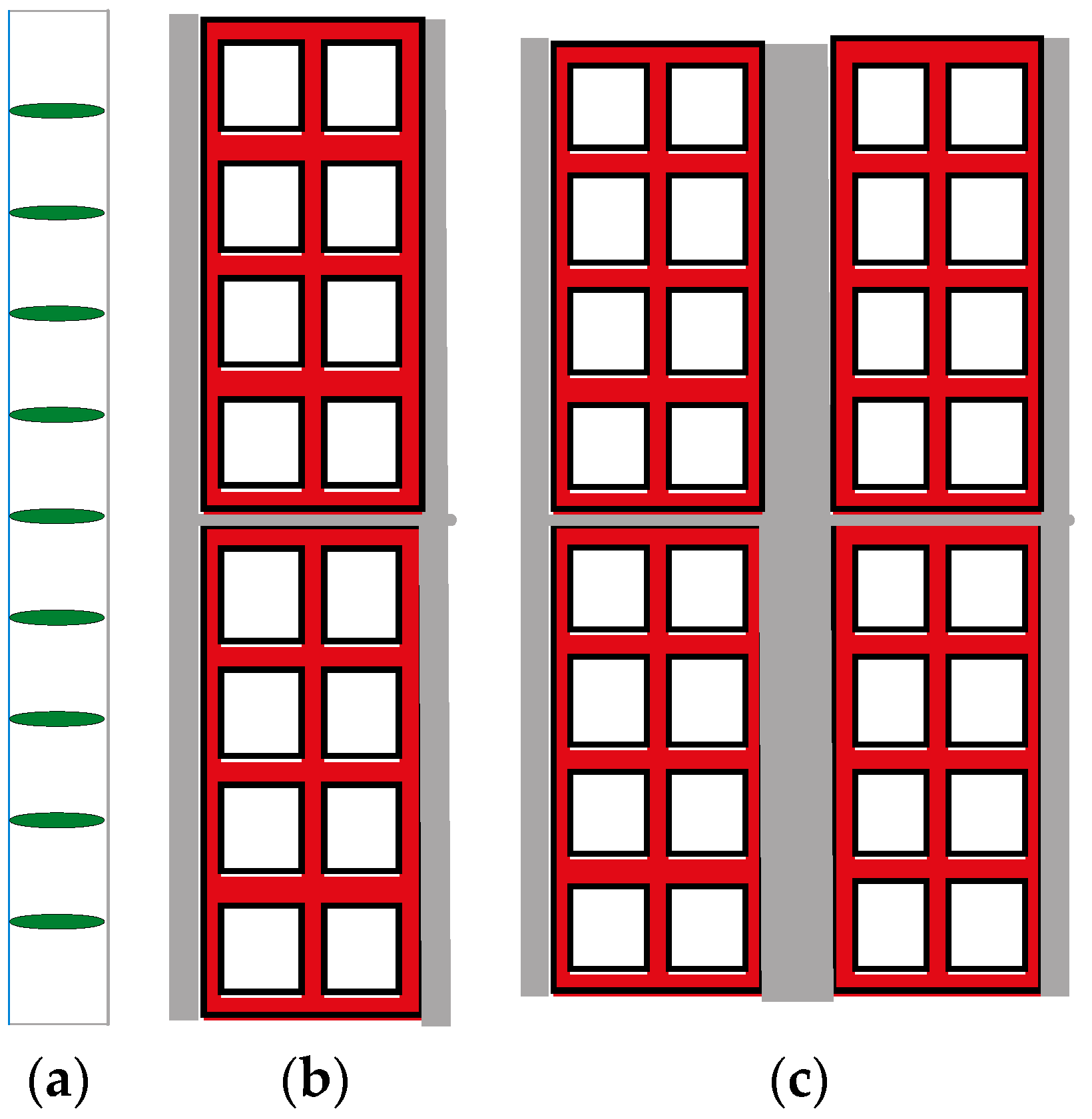
Figure 1 presents the details of the construction elements of the auditorium. Figure 1a shows the DSF system, Figure 1b presents the single-brick scheme, and Figure 1c shows the double-brick scheme.
The semi-circular DSF system included nine articulated lamellae with 40 cm spacing in the vertical direction, 40 cm wide, and 6 cm thick. In the present simulation, the vertical position was used. However, in order to optimise the incident solar radiation, the incidence angle could be changed.
The glass considered in the semi-circular DSF system turned to the south direction and the windows turned to the north direction had a thickness of 4 mm.
The single bricks had a thickness of 20 cm, while the double bricks had a thickness of 40 cm. In the numerical simulation, the single and double bricks presented parallel and series thermal resistance.
The ceiling included different materials, such as gypsum board, insulation materials, cement, intermediary materials, wood, impermeable materials, and roof tiles, with a thickness of 50 cm.
The floor was divided into several layers. The layer farther from the ground presented a small thickness, while the layer closer to the ground presented a higher thickness. The depth considered for the floor was 40 m.
3.3. Building Geometry
The main objective of this work was the numerical application of a semi-circular double-skin façade in an auditorium. The main geometries of the DSF and auditorium used in the numerical model are presented in this subsection. Other details, such as seats, desks, and furniture, were not considered in the numerical model. In the following representations, the solar radiation incidence is also presented.
The approach used for the three-dimensional DSF and auditorium construction considered:
- The two-dimensional vertical section repetition over all opening angles of the DSF system. The two-dimensional vertical section is presented in Figure 2. Figure 3 and Figure 4 show the opening angles of the DSF system considered in the six cases studied. The two-dimensional vertical section repetition over all opening angles of the DSF system for the six cases studied is presented in Figure 5 and Figure 6.
Figure 2 shows the scheme of a section of the auditorium and the respective dimensions. Figure 2a shows the two-dimensional vertical sections, Figure 2b the identification of the bodies and areas, Figure 2c the horizontal dimensions, and Figure 2d the vertical dimensions. In Figure 2b, the labels a, b, c, d, and e indicate, respectively, the lamellae, DSF glass, single bricks, window and door glass, and ceiling. In Figure 2b, the labels A, B, C, and D indicate, respectively, the stage, lower corridor, seats, upper corridor, and ground.
Figure 3 and Figure 4 show the scheme of the auditorium and the details of the opening angle of the DSF system. In Figure 3, Case A, Case B, and Case C are presented, while in Figure 4, Case D, Case E, and Case F are shown.
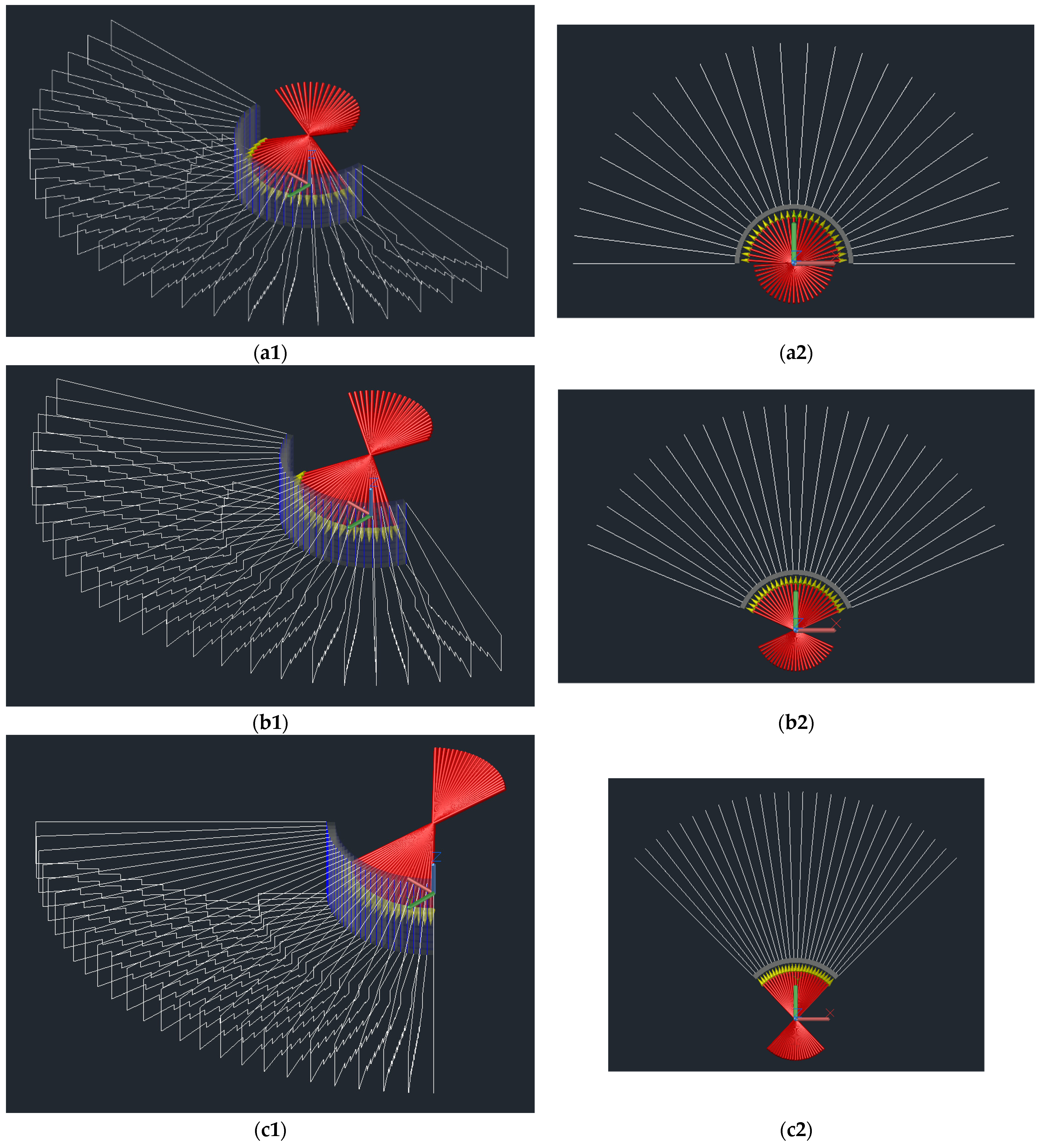
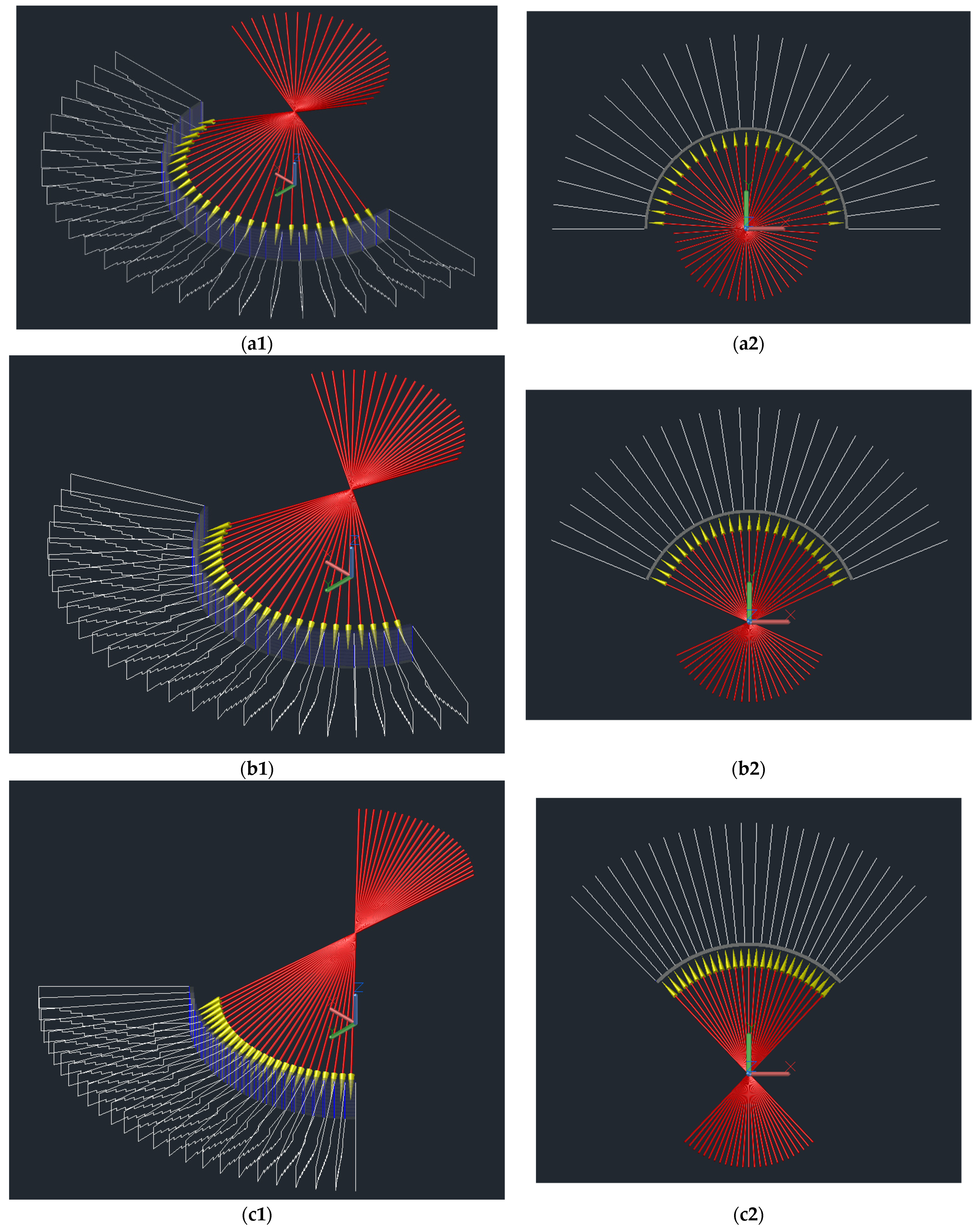
Figure 5 and Figure 6 present the scheme of the auditorium construction methodology, using a two-dimensional vertical section, and the semi-circular DSF solar radiation. In Figure 5, Case A, Case B, and Case C are presented, while in Figure 6, Case D, Case E, and Case F are shown. In these figures, the repetition of the two-dimensional vertical section over all opening angles of the DSF system is presented.
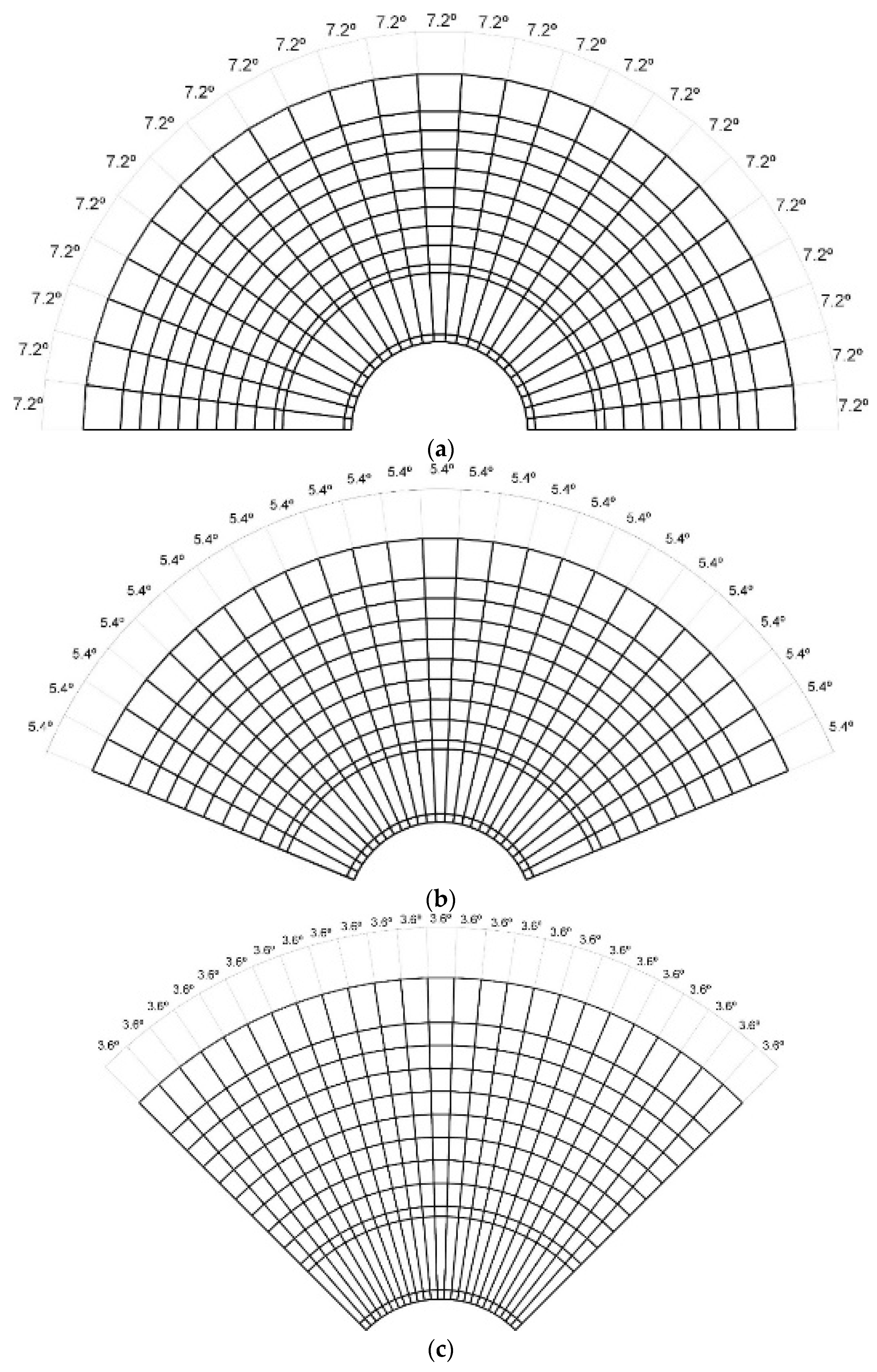
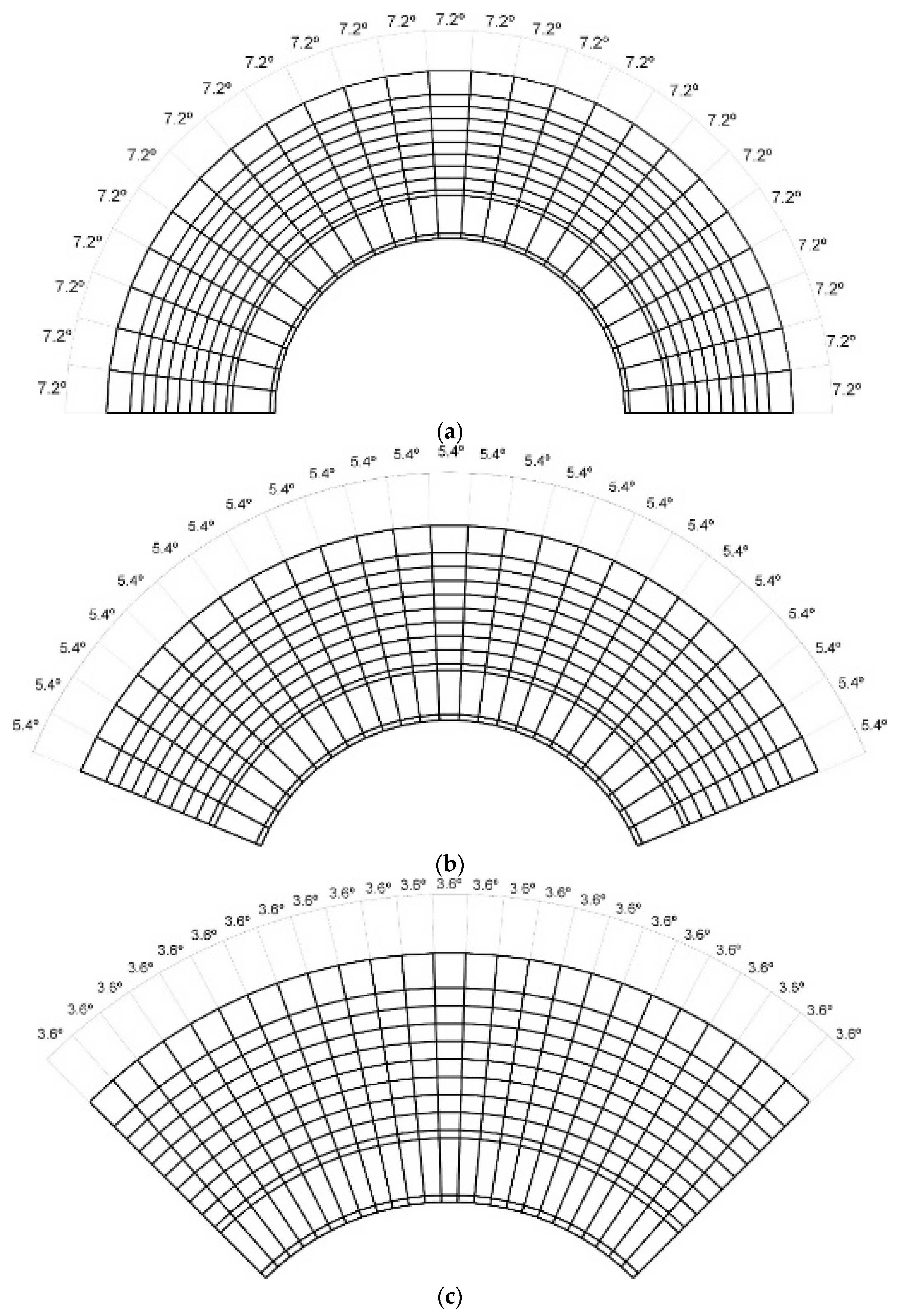
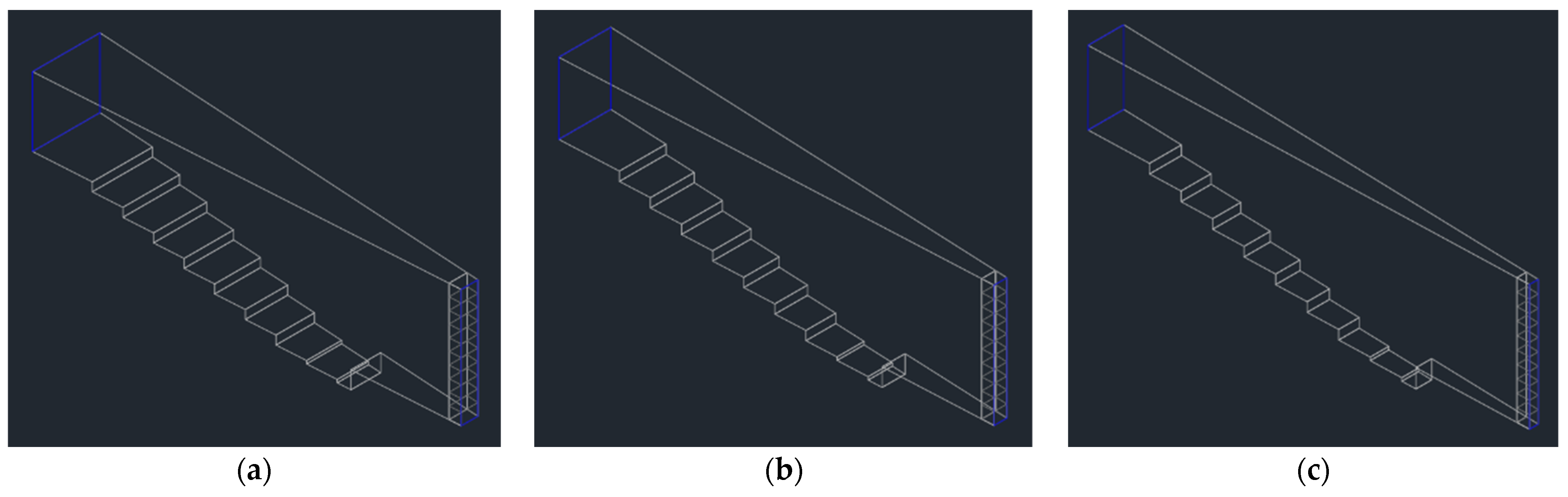
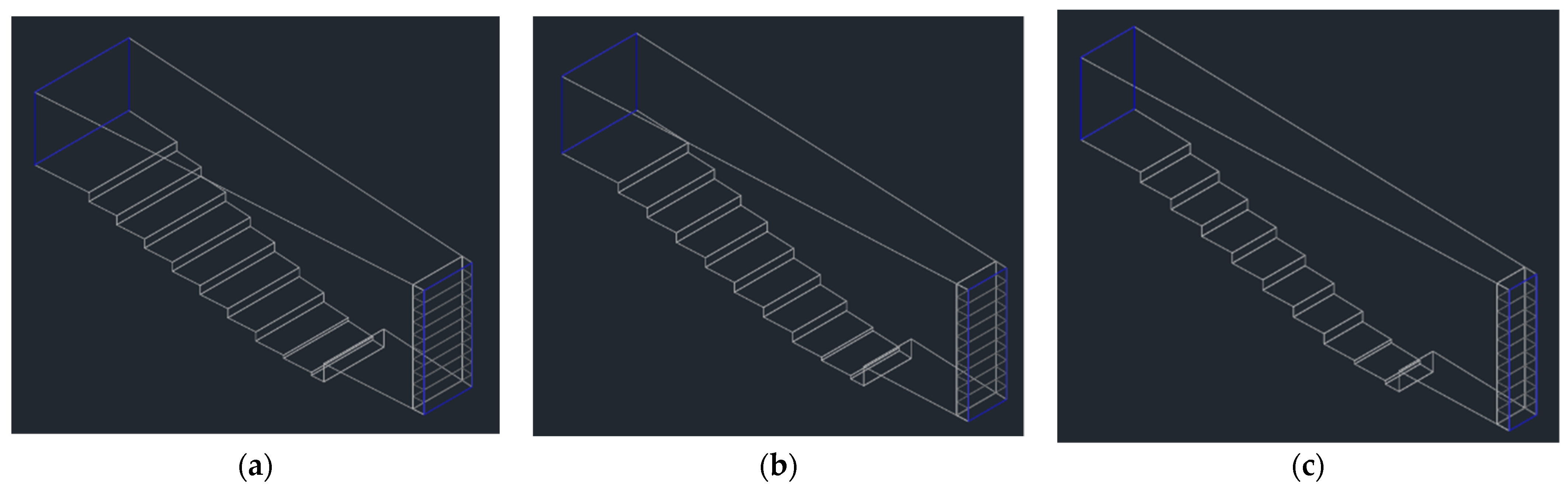
Figure 7 and Figure 8 present the scheme of the auditorium construction methodology, using a two-dimensional horizontal section. Figure 7a–c represent Case A, Case B, and Case C, respectively. Figure 8a–c represent Case D, Case E, and Case F, respectively.
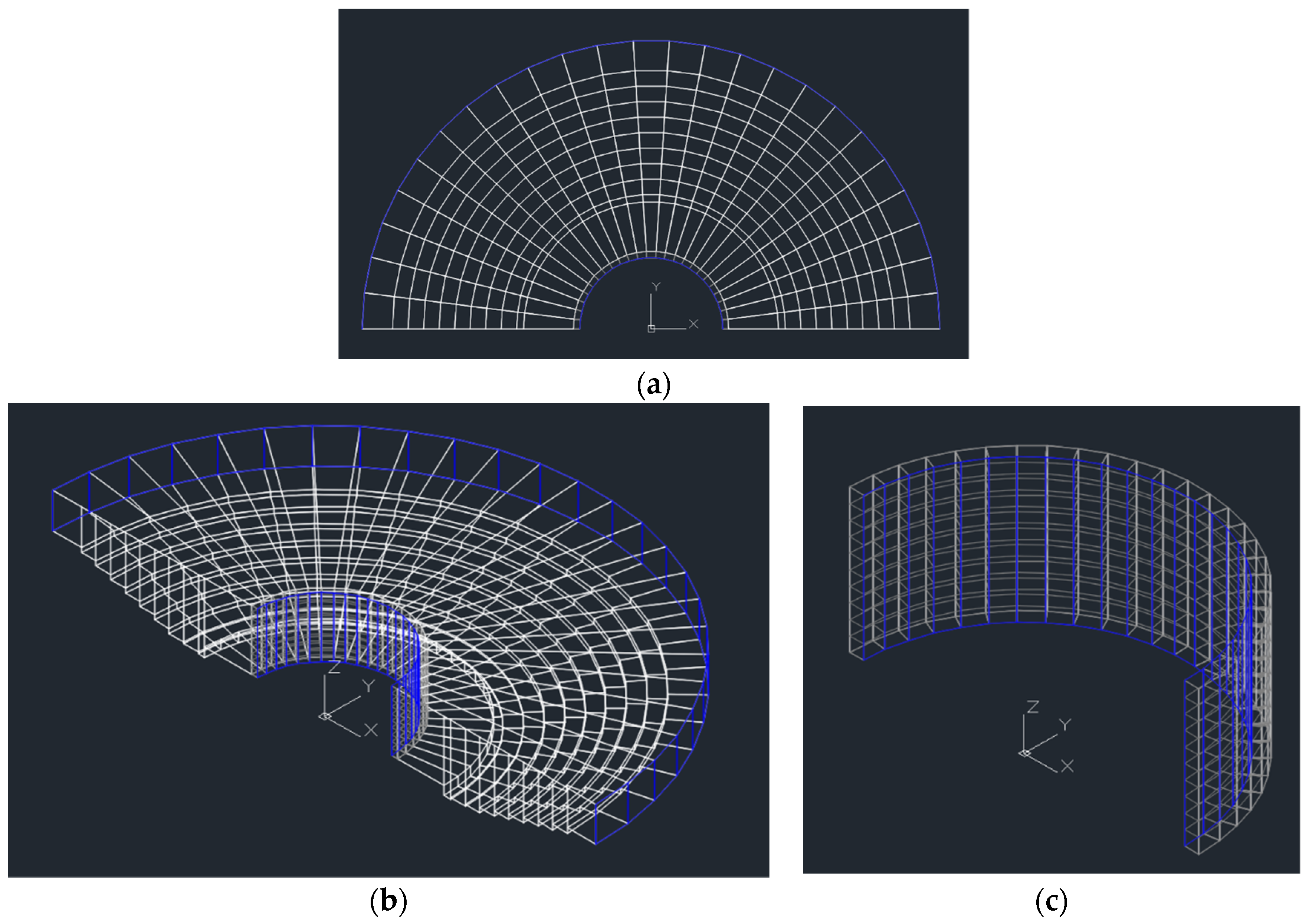
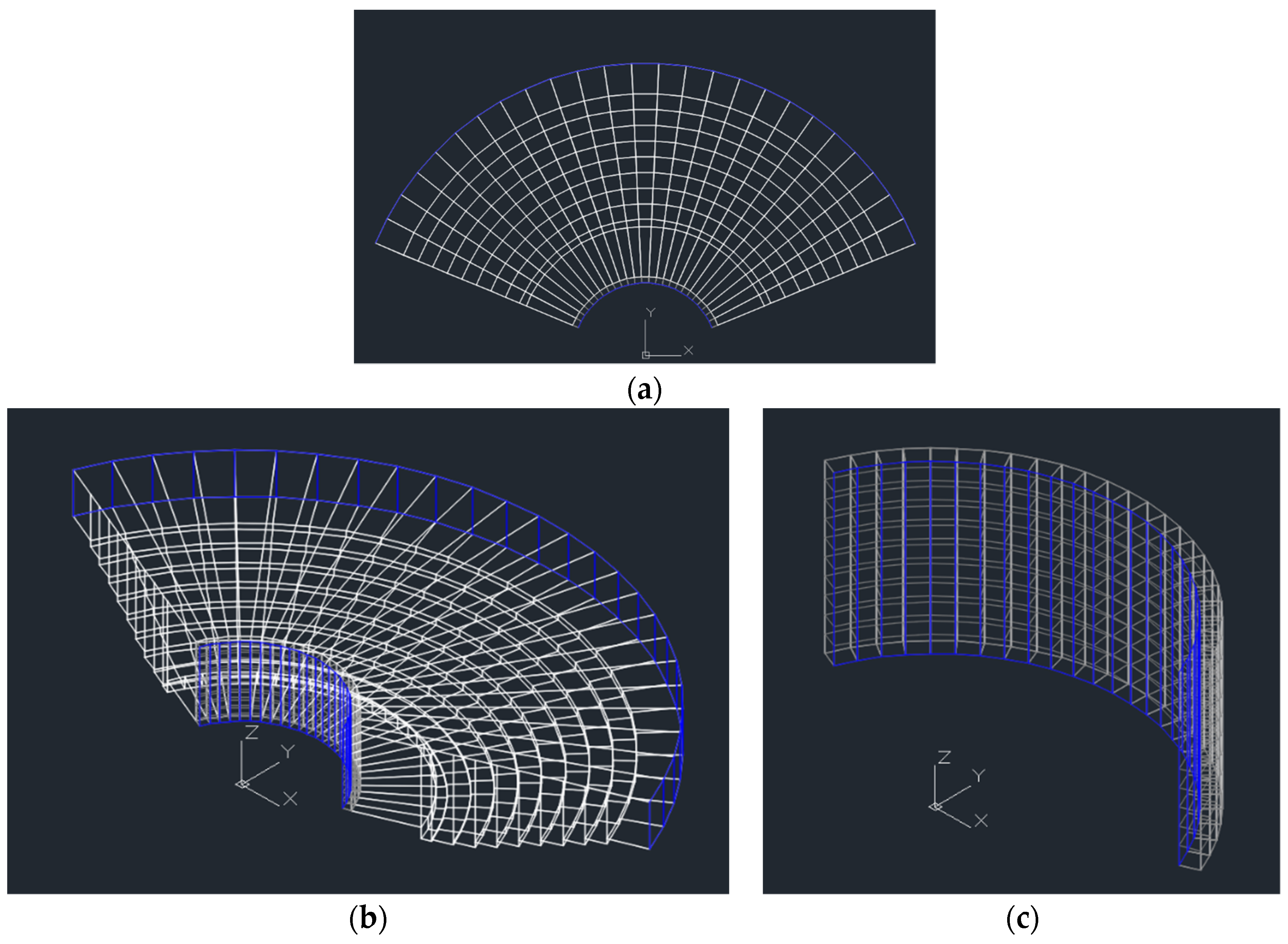
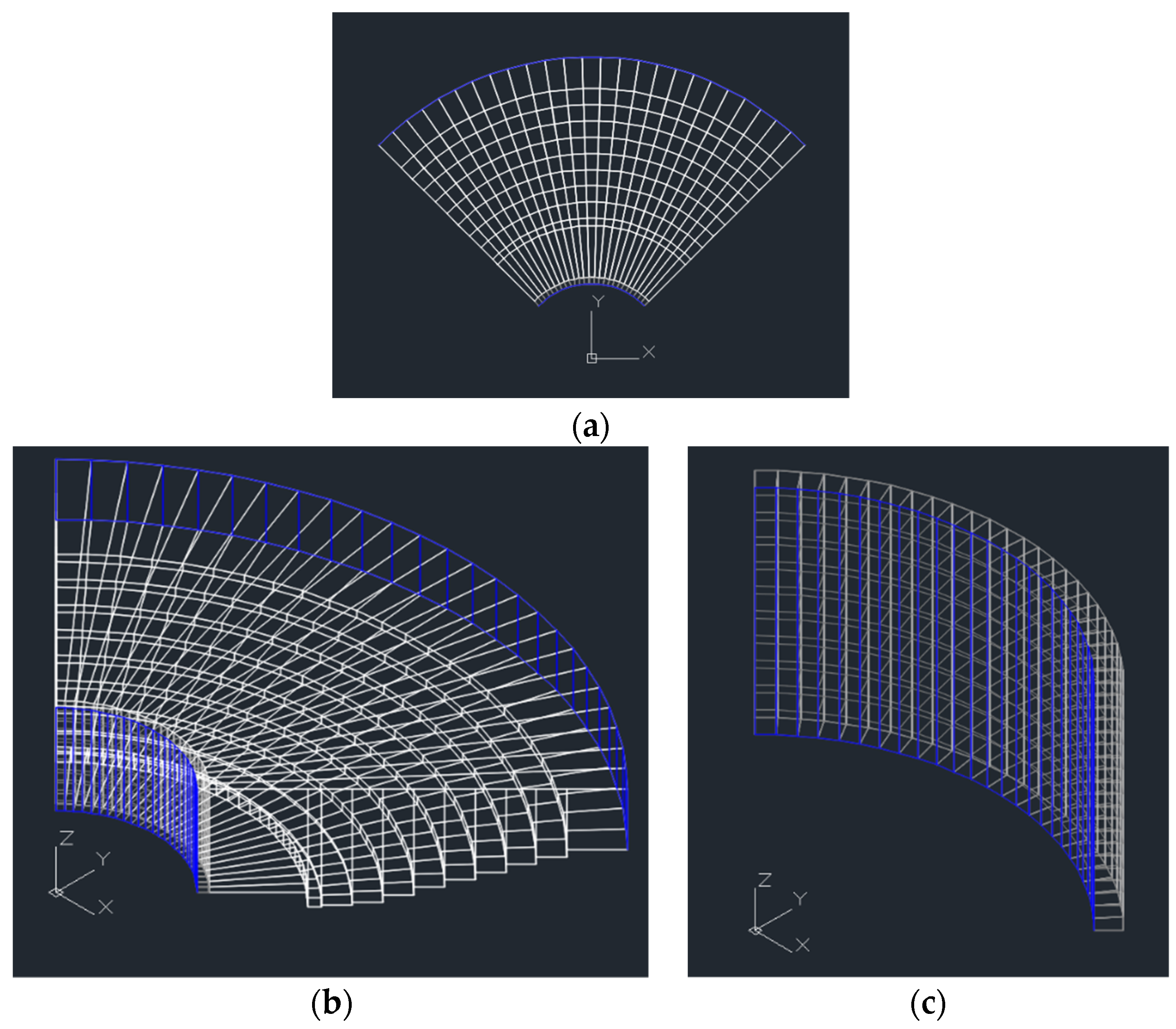
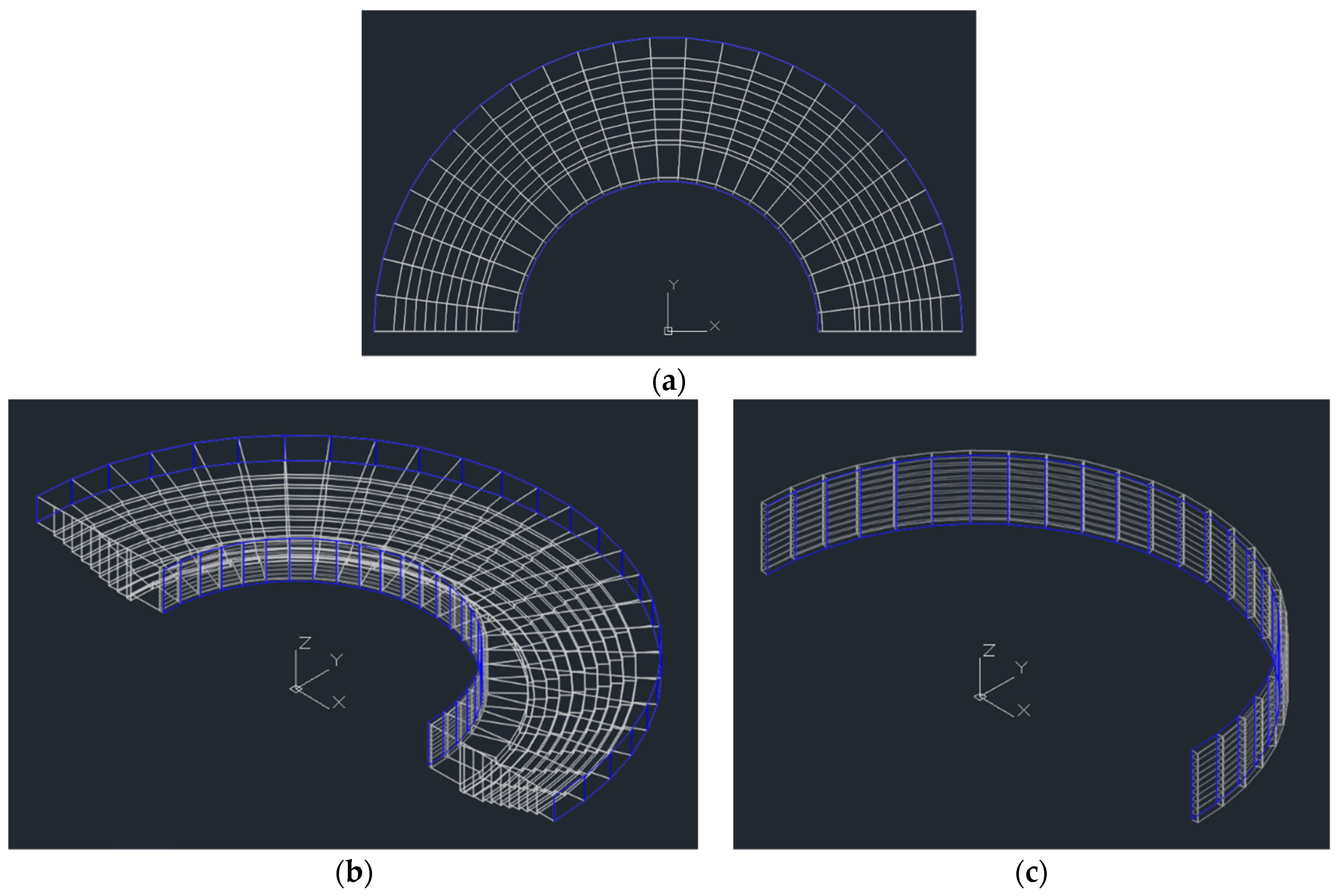
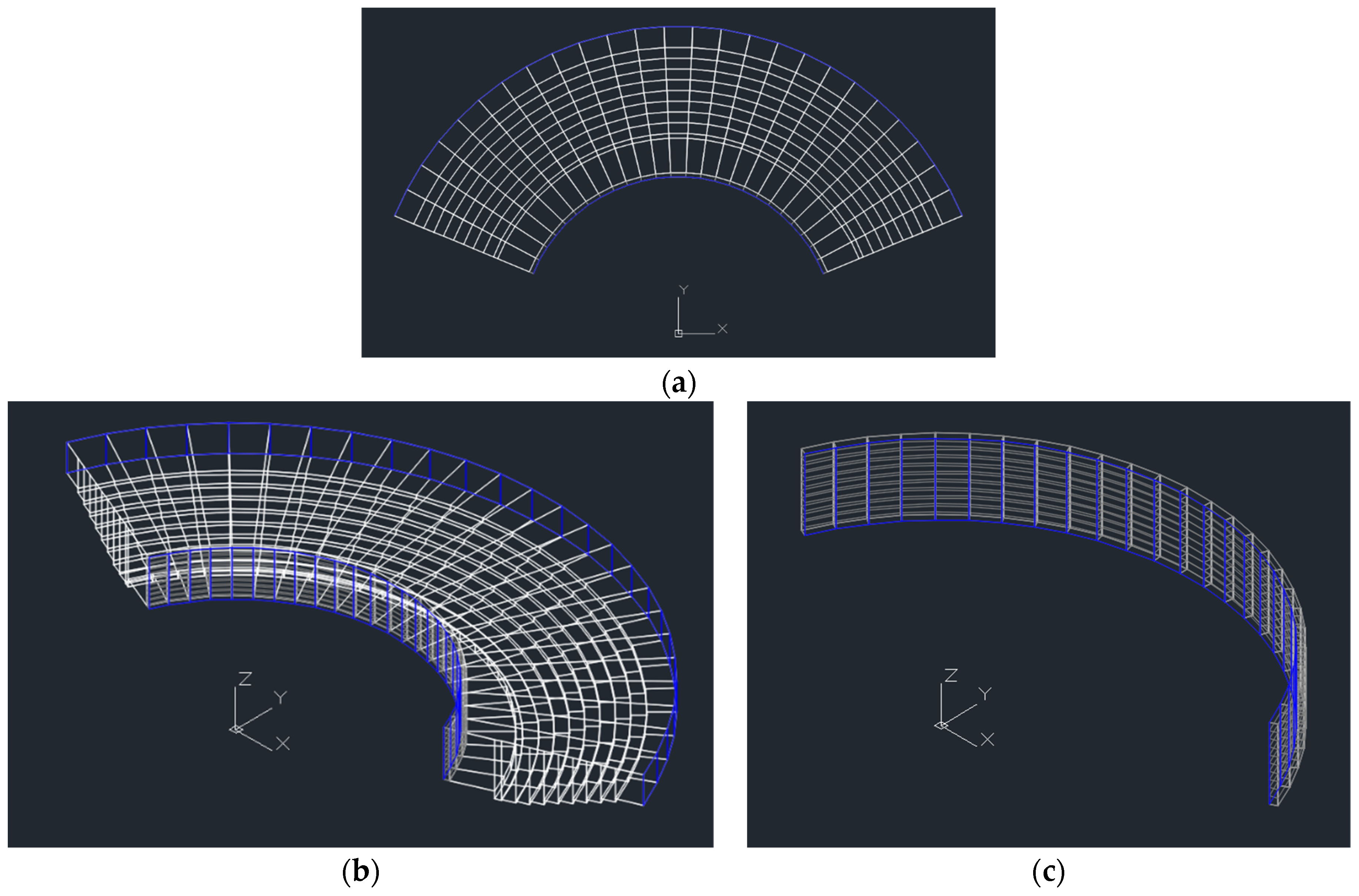
Figure 9, Figure 10, Figure 11, Figure 12, Figure 13 and Figure 14 show the virtual auditorium developed, respectively, in Cases A, B, C, D, E, and F. The white colour represents opaque bodies, and the blue colour represents transparent bodies. Figure 9, Figure 10, Figure 11, Figure 12, Figure 13 and Figure 14 (of index a) represents the top view of the auditorium and the semi-circular DSF, Figure 9, Figure 10, Figure 11, Figure 12, Figure 13 and Figure 14 (of index b) represents the three-dimensional southeast view of the auditorium and the semi-circular DSF, and Figure 9, Figure 10, Figure 11, Figure 12, Figure 13 and Figure 14 (of index c) represents the three-dimensional southeast view of the semi-circular DSF. The x-axis shows the east direction, the y-axis shows the north direction, and the z-axis shows the height level.
In accordance with the Figures, when the opening angle of the DSF system increased, the auditorium volume and the DSF volume increased, and when the radius of the semi-circular DSF system increased, the auditorium volume and the DSF volume also increased.
4. Results and Discussion
In this section, we begin by analysing and discussing the results obtained regarding the evolution of solar radiation transmitted into the auditorium through the outer glazed surfaces of the DSF for each of the six cases described in the previous section. Then, comparatively considering the same six cases, the results obtained for indoor air quality, indoor air temperature, and the level of thermal comfort in the auditorium are analysed and discussed.
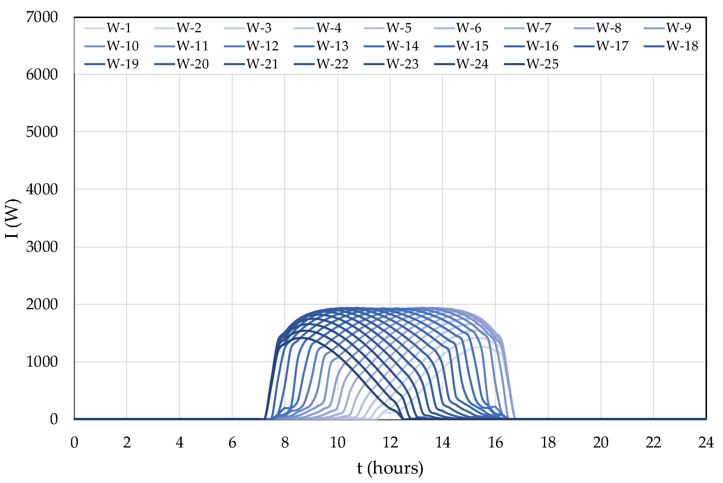
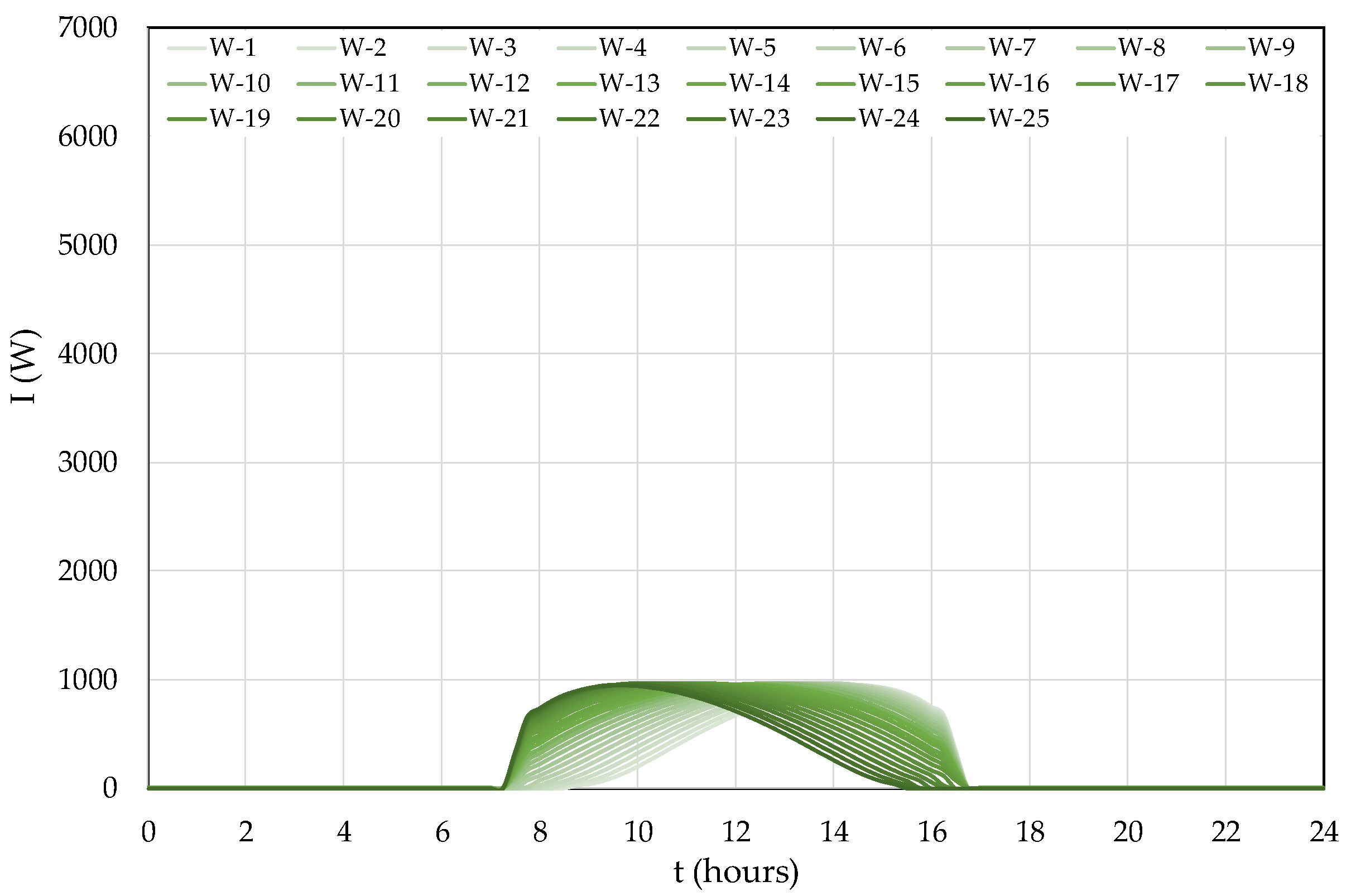
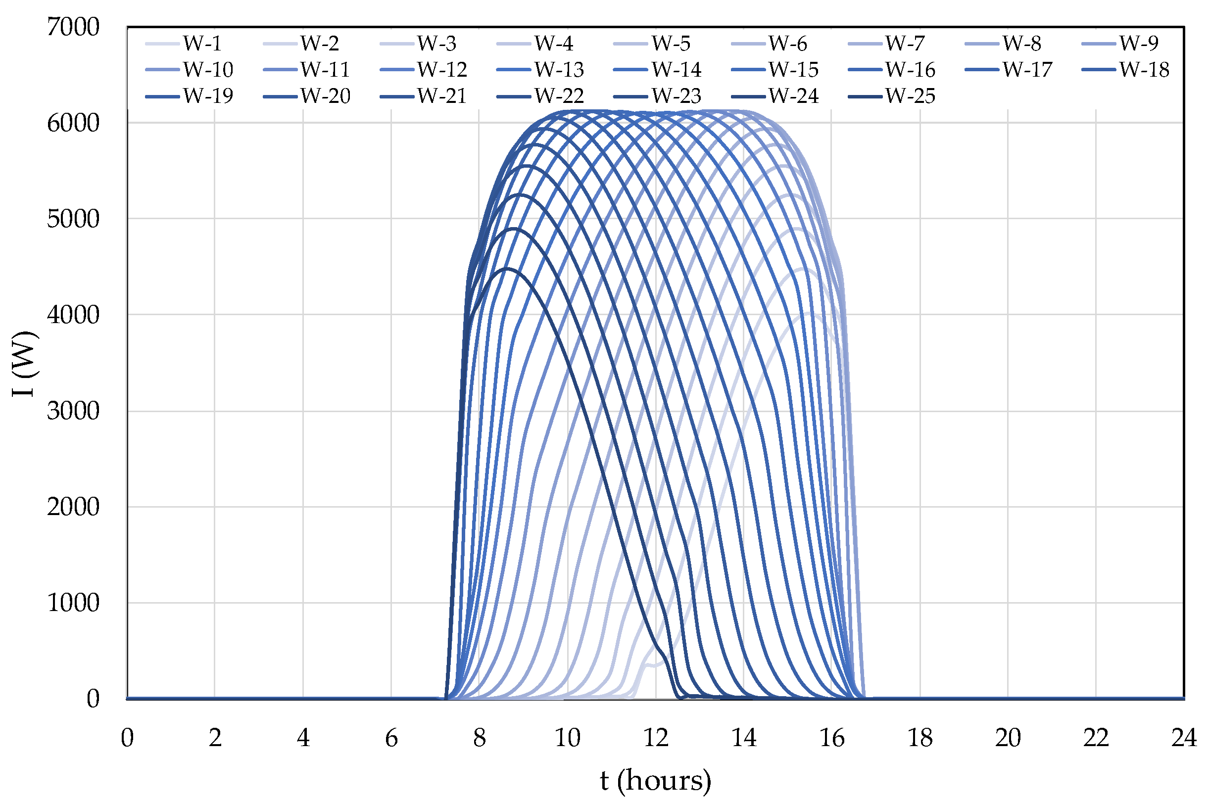
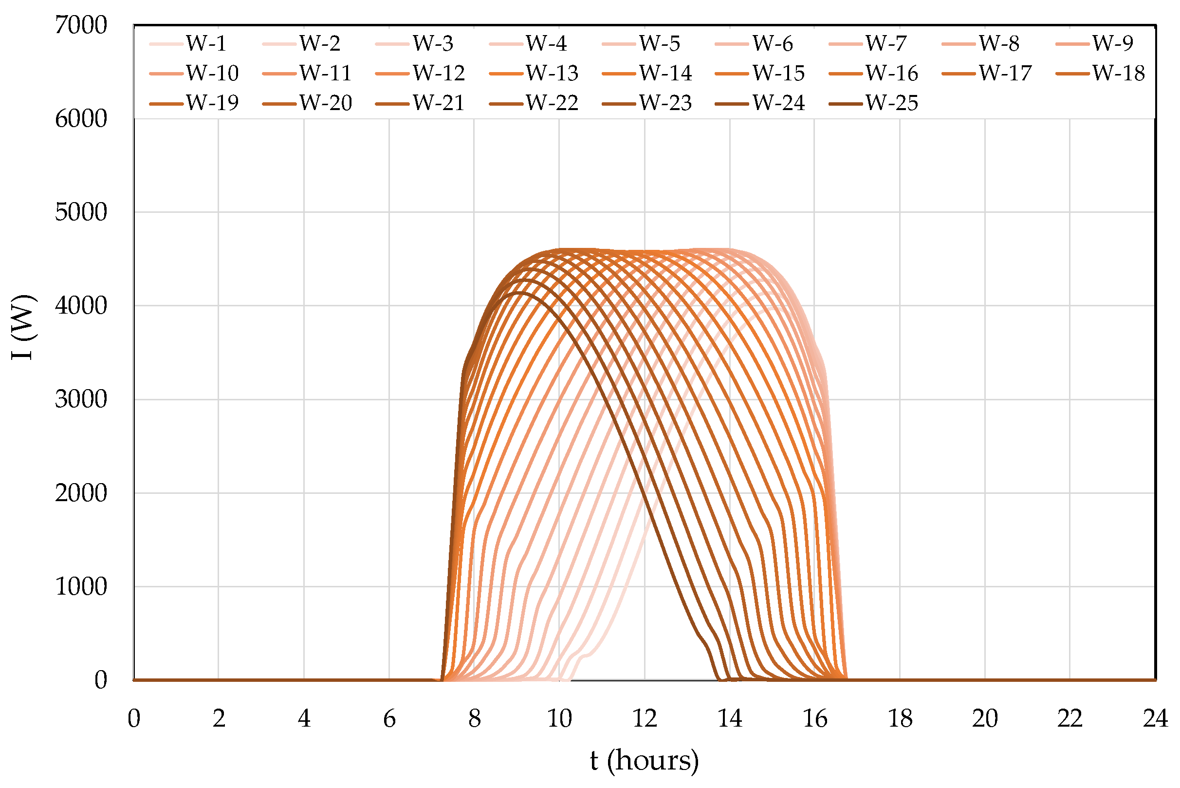
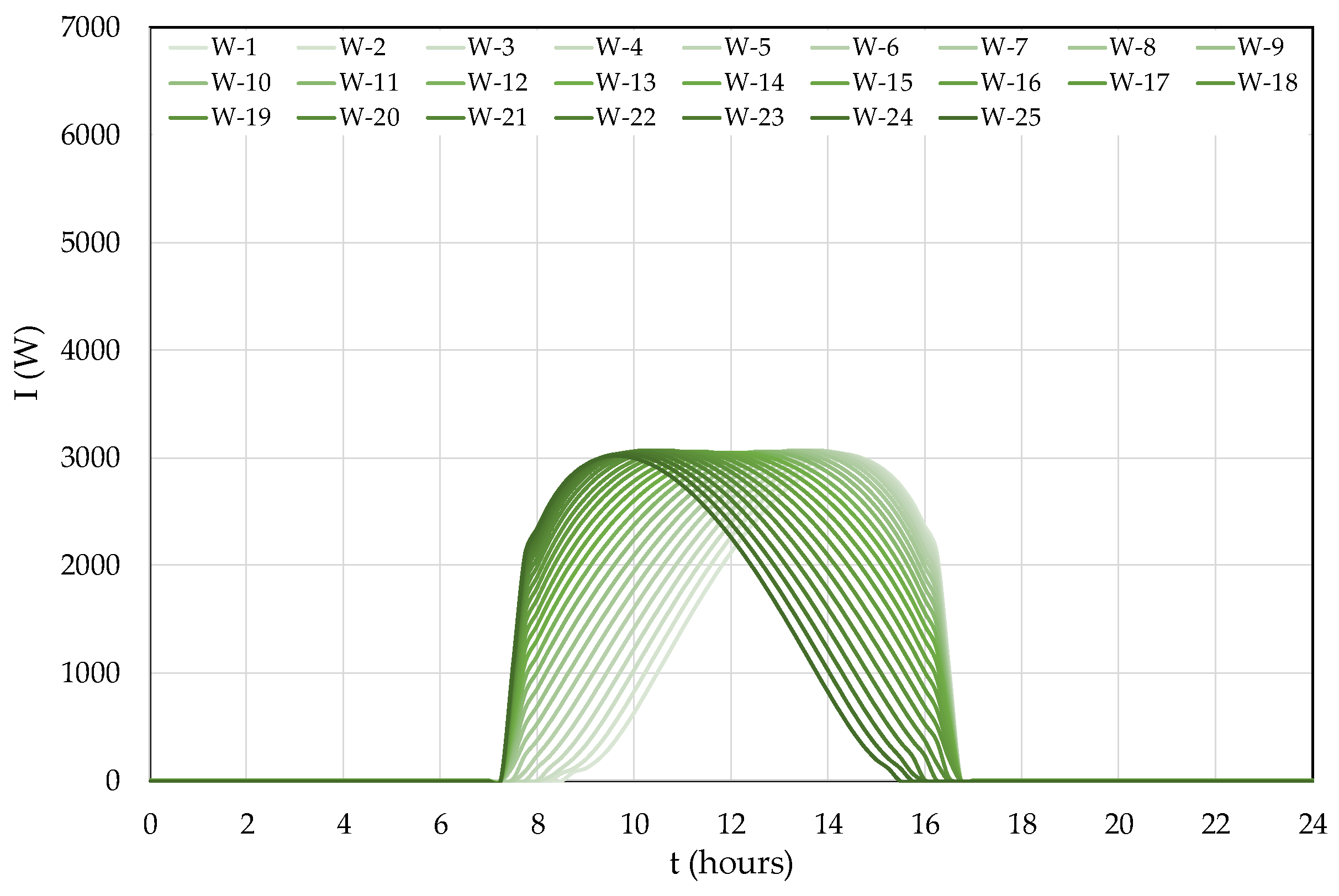
The results obtained regarding the evolution of solar radiation transmitted through the DSF into the auditorium for Cases A, B, C, D, E, and F can be seen, respectively, in Figure 15, Figure 16, Figure 17, Figure 18, Figure 19 and Figure 20. Glazed surface 1 corresponds to the surface mounted on the DSF installed in the easternmost area of the auditorium envelope, while glazed surface 25 corresponds to that mounted on the DSF installed in the westernmost area of the auditorium envelope.
As the results demonstrate, when the opening angle of the DSF system and the radius of the semi-circular DSF system with external glazing surfaces increased, the amount of transmitted solar radiation also increased. This was due to a corresponding increase in the glazed surface area. When the opening angle of the DSF system increased by 45°, there was an increase of about 50% in the amount of available transmitted solar radiation. When the radius of the semi-circular DSF system was tripled, there was an increase of about 300% in the amount of available transmitted solar radiation. Therefore, Case C corresponds to the auditorium envelope in which the amount of available transmitted solar radiation was the smallest, and case D corresponds to the auditorium envelope in which the amount of available transmitted solar radiation was the largest.
The DSF installed in the westernmost area of the auditorium envelope received most of the incident solar radiation in the early morning, while the DSF installed in the easternmost area of the auditorium envelope received most of the incident solar radiation in the late afternoon. The DSFs installed in these areas received low amounts of incident solar radiation due to their position relative to the solar incidence and their adaptation to the curved design of the envelope where they were mounted, because they were shaded most of the time.
About 50% of the DSFs, those located in the central area of the auditorium envelope, were subject to high amounts of solar radiation for a long time. Thus, these DSFs reached the highest peaks of solar radiation between 9:00 (DSFs located further west) and 15:00 (DSFs located further east). For example, the peak of solar radiation incident on the DSF located in the middle of the facade (DSF number 13) was reached at noon. In each case, the values of these peaks were the same, although they were obviously obtained at different times.
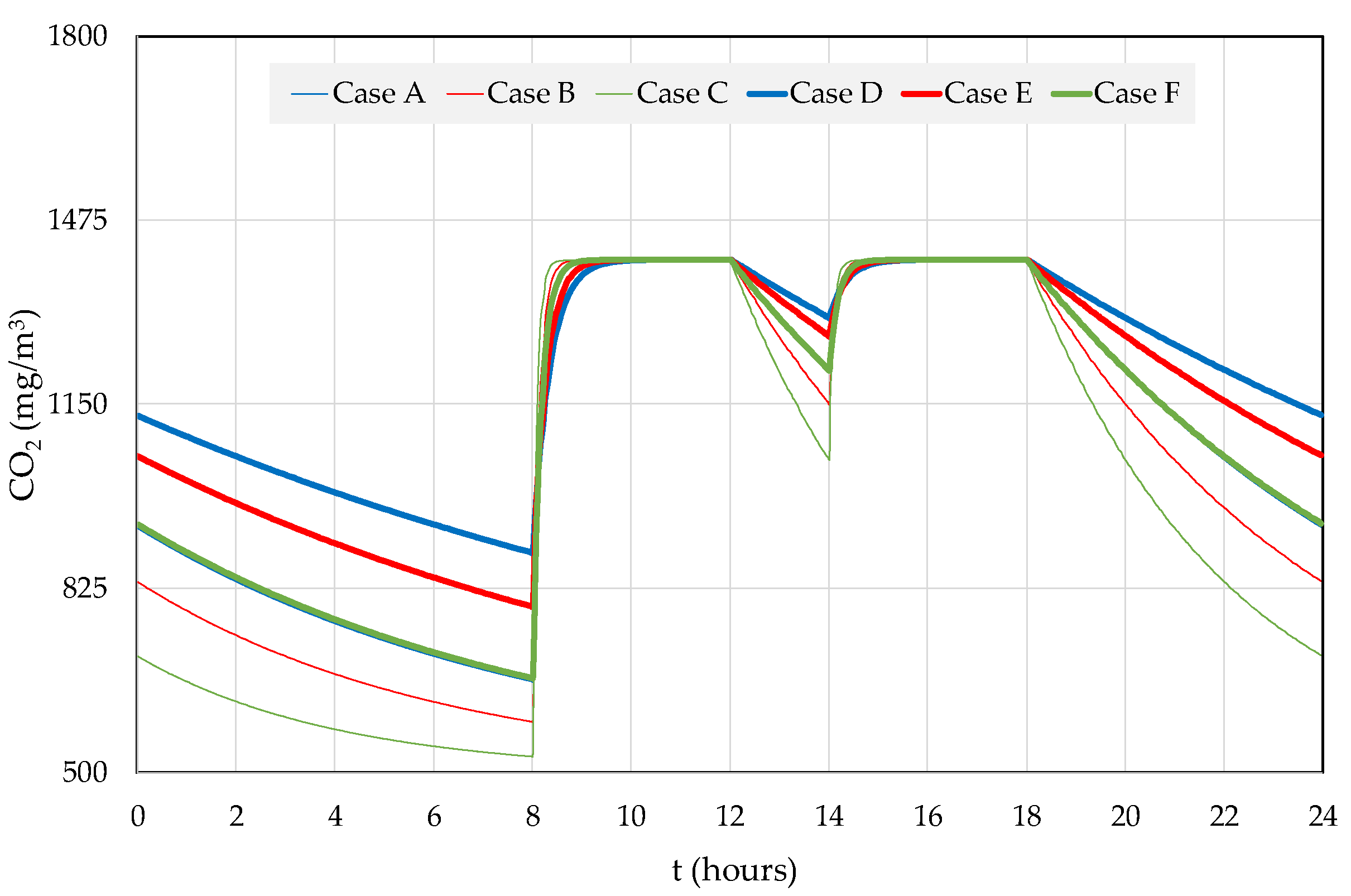
The air quality inside the auditorium was evaluated by the concentration of CO2 measured therein. Figure 21 presents the evolution of the CO2 concentration numerically obtained for each of the six cases studied. As can be seen, it was verified for all cases that the CO2 concentration values were below the acceptable limit (that is, below 1800 mg/m3, ASHRAE-62 [34]); thus, the indoor air quality could be considered suitable for the number of occupants in the auditorium. These results showed that the ventilation system was properly designed to guarantee acceptable indoor air quality for the 100 occupants of the auditorium, depending on the variation in the volume of the space. Note that the smallest auditorium volume was obtained in Case C, and the largest auditorium volume was obtained in Case D. When the auditorium was unoccupied, the CO2 concentration was higher for Case D and lower for Case C, because it depended on the air exchange rate. However, during occupancy, the CO2 concentration depended on the airflow rate and the number of occupants, so its value could almost always be held constant regardless of the volume of the auditorium, that is, around 1400 mg/m3 for all cases.
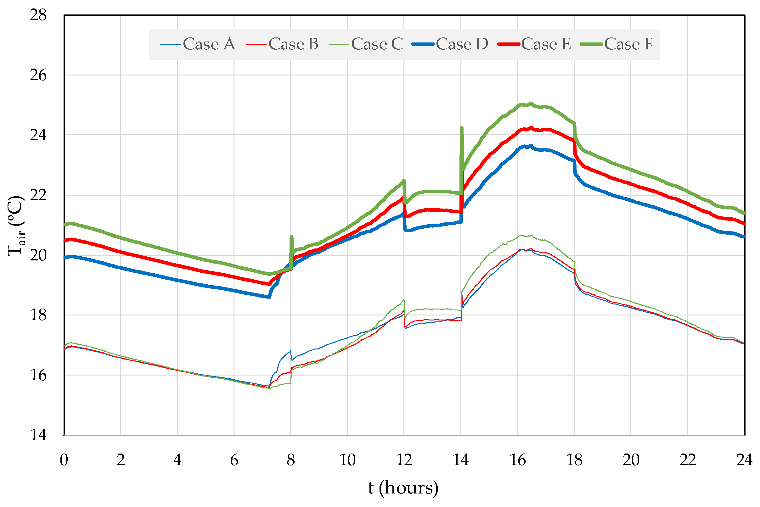
The evolution of indoor air temperature for each of the six cases studied in this work is presented in Figure 22. For all cases, the indoor air temperature in the auditorium increased progressively between 7:00 and 16:00. This evolution of the indoor air temperature essentially depended on the performance of the DSF system and the respective contribution provided by the incident solar radiation on its glazed surfaces, which naturally heated the air that was introduced into the interior of the auditorium by the ventilation system connected to the DSF system. From 16:00 onwards, the DSF system was inoperative due to the absence of solar radiation, which meant that the temperature of the indoor air decreased until the moment when, the following day, the DSF system became operational again. The indoor air temperature was also increased by the occupation of the auditorium, due to the heat released by the human body during its metabolic processes.
For Cases A, B, and C, in which the radius of the semi-circular DSF system was equal to 5 m, the indoor air temperature varied between 15.6 °C, obtained at around 7:15, and 20.7 °C, obtained at around 16:00. On the other hand, for Cases D, E, and F, in which the radius of the semi-circular DSF system was equal to 15 m, the indoor air temperature varied between 18.6 °C, obtained at around 7:15, and 25.1 °C, obtained at around 16:00. As can be seen, the temperature of the indoor air increased by about 3 °C to 5 °C when the radius of the semi-circular DSF system increased from 5 m to 15 m. This was due to the increase in the glazed surface area of the DSF system, which increased the heating power provided by the incident solar radiation on this surface.
Comparing the variation in the opening angle of the DSF system for Cases A, B, and C, in which the radius of the semi-circular was smaller, it was verified that the differences in the temperature of the interior air obtained were not very significant. However, during the afternoon, it was noted that the indoor air temperature obtained for Case C was about 0.5 °C higher than the indoor air temperature obtained for Cases A and B. This was due to the interior volume of the auditorium in Case C being smaller than that in Cases A and B and thus needing less heating power.
Comparing the variation in the opening angle of the DSF system for Cases D, E, and F, in which the radius of the semi-circular was greater, it was verified that the temperature of the interior air increased with a decrease in this angle, that is, it was larger for Case F and smaller for Case D. During the morning, the differences were not very significant, while during the afternoon the indoor air temperature differences between each of these cases were around 0.6 °C–0.7 °C. This was because the interior volume of the auditorium decreased with a decrease in the opening angle of the DSF system curvature, so the need for heating power also decreased. As this heating power was proportional to the glazed surface area of the DSF system, the negative effect of reducing this area was offset by the positive effect of reducing the volume of indoor air to be heated.
In all the cases studied herein, the DSF system managed to provide, in typical winter conditions, interior air temperatures in the auditorium that remained above the exterior temperature, even during the period with the absence of solar radiation, when it was inoperative.
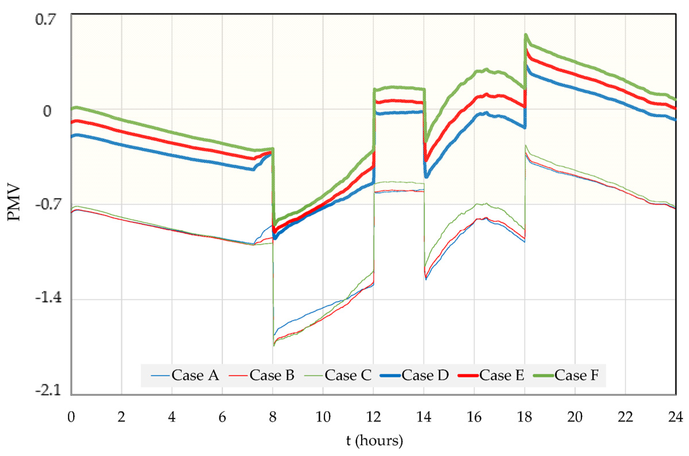
The level of thermal comfort inside the auditorium was evaluated by the PMV index (ISO 7730 [28] and ASHRAE-55 [29]). Figure 23 shows the evolution of the PMV index for each of the six cases studied. The shaded zone in Figure 23 represents the thermal comfort zone considered acceptable for auditorium occupants, which complied with Category C defined by ISO 7730 [28]. As can be seen, in Cases A, B, and C, the level of thermal comfort during the occupancy period was not acceptable for the occupants. On the other hand, for Cases D, E, and F, the level of thermal comfort during the period of occupancy was acceptable for occupants, according to Category C (ISO 7730 [28]), from mid-morning and throughout the afternoon.
It was also noted that, during the occupation period for all six cases studied herein, the evolution of the PMV index followed the evolution of the indoor air temperature, as this is one of the environmental variables on which the PMV index depends. Therefore, during this period of occupancy, the level of thermal comfort increased until around 16:00, after which it decreased. Hence, the level of thermal comfort increased with the increase in the radius of the semi-circular DSF system and with the decrease in the opening angle of the DSF system, the latter design detail being most notable when considering Cases D, E, and F.
5. Conclusions
In this article, a numerical study was presented on the thermal performance of a new DSF system installed on a facade of an auditorium whose shape was semi-circular. The DSF system consisted of 25 smooth DSF systems whose outer surface (skin) was glazed, and the inner surface (skin) was the facade of the auditoriums. The two surfaces were separated by an air channel, equipped inside with a 10-lamella system. The thermal performance was evaluated by the level of thermal comfort provided to the occupants of the auditorium, considering that the facade could be designed with two different radii of the semi-circular DSF (5 m and 15 m) and, for each radius of the semi-circular DSF system, there were three different DSF opening angles (180°, 90°, and 45°), thus constituting six case studies (Cases A, B, C, D, E, and F). Regarding the thermal components, we also evaluated the indoor air quality in the auditorium, which depended on the airflow rate, the number of occupants, and the volume of the interior space.
The numerical study was carried out by coupling two numerical models: the building geometrical design and the building thermal dynamic models. The first was used to generate the three-dimensional mesh geometry of the DSF and the auditorium system, which was used as the input for the second numerical model. The building thermal dynamic was used to calculate, among other variables, the evolution of the indoor air temperature, the PMV index, and the CO2 concentration.
According to the obtained results, the following conclusions were obtained:
- The results obtained regarding the daily evolution of solar radiation allowed us to conclude that the semi-circular DSF system received incident solar radiation from different directions throughout the day (between 7:30 and 16:30), considering a typical winter day with a clear sky. This made it possible to increase the available solar heating power, distributing it more effectively throughout the day. The results also showed that this heating power depended on the area of the glazed surface. Therefore, Case D (radius of 15 m and DSF opening angle of 180°) presented the highest available heating power values, and Case C (radius of 5 m and DSF opening angle of 45°) presented the smallest available heating power values. These values directly influenced the evolution of the indoor air temperature and, consequently, the PMV index obtained. Thus, the greater the opening angle of the DSF system and the radius of the semi-circular DSF system, the greater the available solar heating power.
- The indoor air temperature in the auditorium throughout the day had higher values when the radius was 15 m than when the radius was 5 m: the difference varied between 3 °C and 5 °C. For the smallest radius of the semi-circular DSF system, the temperature difference was not significant when the opening angle of the DSF system varied. For the largest radius of the semi-circular DSF system, the temperature was slightly higher when the opening angle of the DSF system was smaller (Case F, 45°), because the volume of air to be heated inside the auditorium was smaller.
- The evolution of the PMV index showed that, when the opening angle of the DSF system varied, the differences between the values of the PMV index were not very significant, regardless of the radius of the semi-circular DSF system used, although it was noted that better PMV index values were obtained for the smallest DSF opening angle. When comparing the values of the PMV index, it was verified that the best results were obtained for the largest radius of the semi-circular DSF (15 m). In this case, it was possible to obtain an acceptable level of thermal comfort for the occupants, according to Category C of ISO 7730 [28], from mid-morning to late afternoon. During the occupation period, until mid-morning, the PMV index values were close to acceptable. In the case of the smallest radius (5 m), it was not possible to obtain an acceptable level of thermal comfort for the occupants. In this case, it was necessary to resort to the support of an additional heating system, which led to higher energy consumption.
In conclusion, using the semi-circular DSF system proposed herein, which operated as a passive heating system, it was possible to obtain acceptable levels of thermal comfort for the occupants by the adequate selection of the radius of the semi-circular DSF system and the opening angle of the DSF system (see, for example, Case F).
Finally, the results also demonstrated that for all cases studied, the indoor air quality in the auditorium was acceptable for occupants for carbon dioxide concentration values below the acceptable limit of 1800 mg/m3, ASHRAE-62 [34]. Therefore, it can be seen that the ventilation system was properly designed to provide adequate airflow rates for the number of occupants and the volume of air inside the auditorium.
In future work, we intend to evaluate the use of the heated air produced by this DSF system in the heating process of different compartments. Each south-facing DSF will be used to provide heated air primarily to north-facing rooms, but also to east-facing and west-facing rooms.
Author Contributions
M.I.C., E.C., M.M.L., J.G. and H.A. contributed equally to the preparation of this manuscript. All authors have read and agreed to the published version of the manuscript.
Funding
The authors acknowledge to the project (SAICT-ALG/39586/2018) of the Algarve Regional Operational Program (CRESC Algarve 2020) under the PORTUGAL 2020 Partnership Agreement, supported by the European Regional Development Fund (ERDF) and the National Science and Technology Foundation (FCT).
Data Availability Statement
Data sharing not applicable.
Conflicts of Interest
The authors declare no conflict of interest.
Nomenclature
| Main symbols | |
| Clo | Clothing level |
| CO2 | Carbon dioxide concentration |
| Cp | Specific heat at a constant pressure (J kg/°C) |
| DSF | Double-skin facade |
| Mass flux (kg/s) | |
| m | Mass (kg) |
| Met | Activity level |
| PMV | Predicted Mean Vote |
| Heat flux (kg/s) | |
| T | Temperature (°C) |
| t | Time (s) |
| Sub-indexes | |
| air | The air in the compartments |
| c | The number of compartments |
| CO2 | The carbon dioxide concentration |
| i | The number of mass phenomena |
| j | The number of energy phenomena |
| l | The number of opaque body layers |
| o | The number of opaque bodies |
| Op | The opaque bodies |
| t | The number of transparent bodies |
| Tr | The transparent bodies |
| w | The water vapor |
References
- Parra, J.; Guardo, A.; Egusquiza, E.; Alavedra, P. Thermal performance of ventilated double skin façades with venetian blinds. Energies 2015, 8, 4882–4898. [Google Scholar] [CrossRef]
- Velasco, A.; Jiménez García, S.; Guardo, A.; Fontanals, A.; Egusquiza, M. Assessment of the Use of venetian blinds as solar thermal collectors in Double Skin Facades in Mediterranean climates. Energies 2017, 10, 1825. [Google Scholar] [CrossRef] [Green Version]
- Hassanli, S.; Hu, G.; Fletcher, D.F.; Kwok, K.C. Potential application of double skin façade incorporating aerodynamic modifications for wind energy harvesting. J. Wind. Eng. Ind. 2018, 174, 269–280. [Google Scholar] [CrossRef]
- Jankovic, A.; Goia, F. Impact of double skin facade constructional features on heat transfer and fluid dynamic behaviour. Build. Environ. 2021, 196, 107796. [Google Scholar] [CrossRef]
- Preet, S.; Mathur, J.; Mathur, S. Influence of geometric design parameters of double skin façade on its thermal and fluid dynamics behavior: A comprehensive review. Sol. Energy 2022, 236, 249–279. [Google Scholar] [CrossRef]
- Yang, S.; Cannavale, A.; Prasad, D.; Sproul, A.; Fiorito, F. Numerical simulation study of BIPV/T double-skin facade for various climate zones in Australia: Effects on indoor thermal comfort. Build. Simul. 2018, 12, 51–67. [Google Scholar] [CrossRef]
- Radmard, H.; Ghadamian, H.; Esmailie, F.; Ahmadi, B.; Adl, M. Examining a numerical model validity for performance evaluation of a prototype solar oriented Double Skin Façade: Estimating the technical potential for energy saving. Sol. Energy 2020, 211, 799–809. [Google Scholar] [CrossRef]
- Ahriz, A.; Mesloub, A.; Djeffal, L.; Alsolami, B.M.; Ghosh, A.; Abdelhafez, M.H.H. The use of Double-Skin Façades to improve the energy consumption of high-rise office buildings in a Mediterranean climate (Csa). Sustainability 2022, 14, 6004. [Google Scholar] [CrossRef]
- Lee, C.-S.; Lee, H.; Choi, M.; Yoon, J. Design optimization and experimental evaluation of photovoltaic double skin facade. Energy Build. 2019, 202, 109314. [Google Scholar] [CrossRef]
- Zhang, Y.; Zhang, Y.; Li, Z. A novel productive double skin façades for residential buildings: Concept, design and daylighting performance investigation. Build. Environ. 2022, 212, 108817. [Google Scholar] [CrossRef]
- Pasut, W.; De Carli, M. Evaluation of various CFD modelling strategies in predicting airflow and temperature in a naturally ventilated double skin façade. Appl. Therm. Eng. 2011, 37, 267–274. [Google Scholar] [CrossRef] [Green Version]
- Xue, F.; Li, X. A fast assessment method for thermal performance of naturally ventilated double-skin façades during cooling season. Sol. Energy 2015, 114, 303–313. [Google Scholar] [CrossRef]
- Ghaffarianhoseini, A.; Ghaffarianhoseini, A.; Berardi, U.; Tookey, J.; Li, D.H.W.; Kariminia, S. Exploring the advantages and challenges of double-skin façades (DSFs). Renew. Sustain. Energy Rev. 2016, 60, 1052–1065. [Google Scholar] [CrossRef]
- Hazem, A.; Ameghchouche, M.; Bougriou, C. A numerical analysis of the air ventilation management and assessment of the behavior of double skin facades. Energy Build. 2015, 102, 225–236. [Google Scholar] [CrossRef]
- Lucchino, E.C.; Goia, F.; Lobaccaro, G.; Chaudhary, G. Modelling of double skin facades in whole-building energy simulation tools: A review of current practices and possibilities for future developments. Build. Simul. 2019, 12, 3–27. [Google Scholar] [CrossRef]
- Luo, Y.; Zhang, L.; Liu, Z.; Xie, L.; Wang, X.; Wu, J. Experimental study and performance evaluation of a PV-blind embedded double skin façade in winter season. Energy 2018, 165, 326–342. [Google Scholar] [CrossRef]
- Balaji, N.; Mani, M.; Reddy, B.V. Dynamic thermal performance of conventional and alternative building wall envelopes. J. Build. Eng. 2018, 21, 373–395. [Google Scholar] [CrossRef]
- Lee, J.; Alshayeb, M.; Chang, J.D. A Study of Shading Device Configuration on the Natural Ventilation Efficiency and Energy Performance of a Double Skin Façade. Procedia Eng. 2015, 118, 310–317. [Google Scholar] [CrossRef] [Green Version]
- Conceição, E.; Gomes, J.; Lúcio, M.M.; Awbi, H. Development of a Double Skin Facade System Applied in a Virtual Occupied Chamber. Inventions 2021, 6, 17. [Google Scholar] [CrossRef]
- Shen, J.; Lassue, S.; Zalewski, L.; Huang, D. Numerical study on thermal behavior of classical or composite Trombe solar walls. Energy Build. 2007, 39, 962–974. [Google Scholar] [CrossRef]
- Conceição, E.Z.E.; Lúcio, M.M.J.R. Numerical simulation of passive and active solar strategies in buildings with complex topology. Build. Simul. 2010, 3, 245–261. [Google Scholar] [CrossRef]
- Conceição, E.; da Silva, M.C.G.; André, J.C.S.; Viegas, D. Thermal behaviour simulation of the passenger compartment of vehicles. Int. J. Veh. Des. 2000, 24, 372. [Google Scholar] [CrossRef] [Green Version]
- Karimipanah, T.; Awbi, H.; Moshfegh, B. The Air Distribution Index as an Indicator for Energy Consumption and Performance of Ventilation Systems. J. Hum.-Environ. Syst. 2008, 11, 77–84. [Google Scholar] [CrossRef] [Green Version]
- Awbi, H. Energy efficient room air distribution. Renew. Energy 1998, 15, 293–299. [Google Scholar] [CrossRef]
- Nielsen, P.V.; Heby, T.; Moeller-Jensen, B. Air distribution in a room with ceiling-mounted Diffusers—Comparison with wall-mounted diffuser, vertical ventilation, and displacement ventilation. ASHRAE Trans. 2006, 112, 498–504. [Google Scholar]
- Cermak, R.; Melikov, A.K.; Forejt, L.; Kovar, O. Performance of personalized ventilation in conjunction with mixing and displacement ventilation. HVAC R Res. 2006, 12, 295–311. [Google Scholar] [CrossRef]
- Fanger, P.O. Thermal comfort: Analysis and applications in environmental engineering. Appl. Ergon. 1972, 3, 181. [Google Scholar] [CrossRef]
- ISO 7730:2005; Ergonomics of the Thermal Environment Analytical Determination and Interpretation of Thermal Comfort Using Calculation of the PMV and PPD Indices and Local Thermal Comfort Criteria. ISO: Geneva, Switzerland, 2005. [CrossRef]
- ANSI/ASHRAE Standard-55; Thermal Environmental Conditions for Human Occupancy. American Society of Heating, Refrigerating and Air-Conditioning Engineers: Atlanta, GA, USA, 2017.
- Yao, R.; Li, B.; Liu, J. A theoretical adaptive model of thermal comfort—Adaptive Predicted Mean Vote (aPMV). Build. Environ. 2009, 44, 2089–2096. [Google Scholar] [CrossRef]
- De Dear, R.; Brager, G.S. Developing an adaptive model of thermal comfort and preference. In ASHRAE Transactions; American Society of Heating, Refrigerating and Air-Conditioning Engineers: Atlanta, GA, USA, 1998. [Google Scholar]
- Nicol, F. Adaptive thermal comfort standards in the hot–humid tropics. Energy Build. 2004, 36, 628–637. [Google Scholar] [CrossRef]
- Conceição, E.Z.E.; Lúcio, M.M.J.R. Numerical simulation of the application of solar radiant systems, internal airflow and occupants’ presence in the improvement of comfort in winter conditions. Buildings 2016, 6, 38. [Google Scholar] [CrossRef] [Green Version]
- ANSI/ASHRAE Standard 62-1; Ventilation for Acceptable Indoor Air Quality. American Society of Heating, Refrigerating and Air-Conditioning Engineers: Atlanta, GA, USA, 2022.
- RECS. Regulamento de Desempenho Energético dos Edifícios de Comércio e Serviços (RECS)—Requisitos de Ventilação e Qualidade do Ar Interior—Portaria no 353-A/2013 de 4 de Dezembro. Diário República, 2013; 1ª série 245. 6644-(2)–6644-(9). [Google Scholar]
- Conceição, E.; Silva, M.C.; Viegas, D.X. Air quality inside the passenger compartment of a bus. J. Expo. Anal. Environ. Epidemiol. 1997, 7, 521–534. [Google Scholar] [PubMed]
- Awbi, H.B. Ventilation for Good Indoor Air Quality and Energy Efficiency. Energy Procedia 2017, 112, 277–286. [Google Scholar] [CrossRef]
- Persily, A.K.; Emmerich, S.J. Indoor air quality in sustainable, energy efficient buildings. Hvac R Res. 2012, 18, 4–20. [Google Scholar] [CrossRef]
- Fanger, P.O. Provide Good air quality for people and improve their productivity. In Proceedings of the Seventh International Conference Air Distribution in Rooms, (ROOMVENT 2000), Reading, UK, 9–12 July 2000. [Google Scholar]
Figure 1.
Details of the auditorium construction elements. (a) DSF system, (b) single-brick scheme, and (c) double-brick scheme.
Figure 1.
Details of the auditorium construction elements. (a) DSF system, (b) single-brick scheme, and (c) double-brick scheme.

Figure 2.
Scheme of a section of the auditorium and the respective dimensions. (a) Two-dimensional vertical section, (b) identification of the bodies and areas, (c) horizontal dimensions, and (d) vertical dimensions.
Figure 2.
Scheme of a section of the auditorium and the respective dimensions. (a) Two-dimensional vertical section, (b) identification of the bodies and areas, (c) horizontal dimensions, and (d) vertical dimensions.

Figure 3.
Scheme of the auditorium and details of the opening angle of the DSF system. (a) Case A, (b) Case B, and (c) Case C. Three-dimensional top view.
Figure 3.
Scheme of the auditorium and details of the opening angle of the DSF system. (a) Case A, (b) Case B, and (c) Case C. Three-dimensional top view.

Figure 4.
Scheme of the auditorium and the details of the opening angle of the DSF system. (a) Case D, (b) Case E, and (c) Case F. Three-dimensional top view.
Figure 4.
Scheme of the auditorium and the details of the opening angle of the DSF system. (a) Case D, (b) Case E, and (c) Case F. Three-dimensional top view.

Figure 5.
Scheme of the auditorium construction methodology, using a two-dimensional vertical section, and the semi-circular DSF solar radiation. (a1,a2) Case A, (b1,b2) Case B, and (c1,c2) Case C. Figures with index 1 represent the three-dimensional southeast view of the semi-circular DSF and the auditorium, while Figures with index 2 represent the top view.

Figure 6.
Scheme of the auditorium construction methodology, using a two-dimensional vertical section, and the semi-circular DSF solar radiation. (a1,a2) Case D, (b1,b2) Case E, and (c1,c2) Case F. Figures with index 1 represent the three-dimensional southeast view of the semi-circular DSF and the auditorium, while Figures with index 2 represent the top view.

Figure 7.
Scheme of the auditorium construction methodology, using a two-dimensional horizontal section. (a) Case A, (b) Case B, and (c) Case C.
Figure 7.
Scheme of the auditorium construction methodology, using a two-dimensional horizontal section. (a) Case A, (b) Case B, and (c) Case C.

Figure 8.
Scheme of the auditorium construction methodology, using a two-dimensional horizontal section. (a) Case D, (b) Case E, and (c) Case F.
Figure 8.
Scheme of the auditorium construction methodology, using a two-dimensional horizontal section. (a) Case D, (b) Case E, and (c) Case F.

Figure 9.
Virtual auditorium developed in Case A. (a) Top view of the auditorium and the semi-circular DSF, (b) tri-dimensional southeast view of the auditorium and the semi-circular DSF, and (c) tri-dimensional southeast view of the semi-circular DSF.
Figure 9.
Virtual auditorium developed in Case A. (a) Top view of the auditorium and the semi-circular DSF, (b) tri-dimensional southeast view of the auditorium and the semi-circular DSF, and (c) tri-dimensional southeast view of the semi-circular DSF.

Figure 10.
Virtual auditorium developed in Case B. (a) Top view of the auditorium and the semi-circular DSF, (b) tri-dimensional southeast view of the auditorium and the semi-circular DSF, and (c) tri-dimensional southeast view of the semi-circular DSF.
Figure 10.
Virtual auditorium developed in Case B. (a) Top view of the auditorium and the semi-circular DSF, (b) tri-dimensional southeast view of the auditorium and the semi-circular DSF, and (c) tri-dimensional southeast view of the semi-circular DSF.

Figure 11.
Virtual auditorium developed in Case C. (a) Top view of the auditorium and the semi-circular DSF, (b) tri-dimensional southeast view of the auditorium and the semi-circular DSF, and (c) tri-dimensional southeast view of the semi-circular DSF.
Figure 11.
Virtual auditorium developed in Case C. (a) Top view of the auditorium and the semi-circular DSF, (b) tri-dimensional southeast view of the auditorium and the semi-circular DSF, and (c) tri-dimensional southeast view of the semi-circular DSF.

Figure 12.
Virtual auditorium developed in Case D. (a) Top view of the auditorium and the semi-circular DSF, (b) tri-dimensional southeast view of the auditorium and the semi-circular DSF, and (c) tri-dimensional southeast view of the semi-circular DSF.
Figure 12.
Virtual auditorium developed in Case D. (a) Top view of the auditorium and the semi-circular DSF, (b) tri-dimensional southeast view of the auditorium and the semi-circular DSF, and (c) tri-dimensional southeast view of the semi-circular DSF.

Figure 13.
Virtual auditorium developed in Case E. (a) Top view of the auditorium and the semi-circular DSF, (b) tri-dimensional southeast view of the auditorium and the semi-circular DSF, and (c) tri-dimensional southeast view of the semi-circular DSF.
Figure 13.
Virtual auditorium developed in Case E. (a) Top view of the auditorium and the semi-circular DSF, (b) tri-dimensional southeast view of the auditorium and the semi-circular DSF, and (c) tri-dimensional southeast view of the semi-circular DSF.

Figure 14.
Virtual auditorium developed in the Case F. (a) Top view of the auditorium and the semi-circular DSF, (b) tri-dimensional southeast view of the auditorium and the semi-circular DSF, and (c) tri-dimensional southeast view of the semi-circular DSF.
Figure 14.
Virtual auditorium developed in the Case F. (a) Top view of the auditorium and the semi-circular DSF, (b) tri-dimensional southeast view of the auditorium and the semi-circular DSF, and (c) tri-dimensional southeast view of the semi-circular DSF.

Figure 15.
Evolution of transmitted solar radiation for the different smooth DSF glass components (Case A).
Figure 15.
Evolution of transmitted solar radiation for the different smooth DSF glass components (Case A).

Figure 16.
Evolution of transmitted solar radiation for the different smooth DSF glass components (Case B).
Figure 16.
Evolution of transmitted solar radiation for the different smooth DSF glass components (Case B).

Figure 17.
Evolution of transmitted solar radiation for the different smooth DSF glass components (Case C).
Figure 17.
Evolution of transmitted solar radiation for the different smooth DSF glass components (Case C).

Figure 18.
Evolution of transmitted solar radiation for the different smooth DSF glass components (Case D).
Figure 18.
Evolution of transmitted solar radiation for the different smooth DSF glass components (Case D).

Figure 19.
Evolution of transmitted solar radiation for the different smooth DSF glass components (Case E).
Figure 19.
Evolution of transmitted solar radiation for the different smooth DSF glass components (Case E).

Figure 20.
Evolution of transmitted solar radiation for the different smooth DSF glass components (Case F).
Figure 20.
Evolution of transmitted solar radiation for the different smooth DSF glass components (Case F).

Figure 21.
Evolution of CO2 concentration for the six cases studied.

Figure 22.
Evolution of internal air temperature (Tair) for the six cases studied.

Figure 23.
Evolution of PMV index for the six cases studied. The comfort zone according to Category C of ISO 7730 [28] is shaded.
Figure 23.
Evolution of PMV index for the six cases studied. The comfort zone according to Category C of ISO 7730 [28] is shaded.


Table 1.
The opening angle of the DSF system and the radius of the curved DSF system.
| Opening Angle of the DSF System (°) | Radius of the Semi-Circular DSF System (m) | |
|---|---|---|
| Case A | 180 | 5 |
| Case B | 135 | 5 |
| Case C | 90 | 5 |
| Case D | 180 | 15 |
| Case E | 135 | 15 |
| Case F | 90 | 15 |
Disclaimer/Publisher’s Note: The statements, opinions and data contained in all publications are solely those of the individual author(s) and contributor(s) and not of MDPI and/or the editor(s). MDPI and/or the editor(s) disclaim responsibility for any injury to people or property resulting from any ideas, methods, instructions or products referred to in the content. |
© 2023 by the authors. Licensee MDPI, Basel, Switzerland. This article is an open access article distributed under the terms and conditions of the Creative Commons Attribution (CC BY) license (https://creativecommons.org/licenses/by/4.0/).
Share and Cite
MDPI and ACS Style
Conceição, M.I.; Conceição, E.; Lúcio, M.M.; Gomes, J.; Awbi, H. Application of Semi-Circular Double-Skin Facades in Auditoriums in Winter Conditions. Inventions 2023, 8, 60. https://doi.org/10.3390/inventions8020060
AMA Style
Conceição MI, Conceição E, Lúcio MM, Gomes J, Awbi H. Application of Semi-Circular Double-Skin Facades in Auditoriums in Winter Conditions. Inventions. 2023; 8(2):60. https://doi.org/10.3390/inventions8020060
Chicago/Turabian StyleConceição, Maria Inês, Eusébio Conceição, Maria Manuela Lúcio, João Gomes, and Hazim Awbi. 2023. "Application of Semi-Circular Double-Skin Facades in Auditoriums in Winter Conditions" Inventions 8, no. 2: 60. https://doi.org/10.3390/inventions8020060