
Metal Wire Additive Manufacturing: A Comparison between Arc Laser and Laser/Arc Heat Sources

Department of Mechanics, Mathematics and Management, Polytechnic University of Bari, Via Orabona 4, 70125 Bari, Italy
*
Author to whom correspondence should be addressed.
Inventions 2023, 8(2), 52; https://doi.org/10.3390/inventions8020052
Submission received: 30 January 2023
/
Revised: 21 February 2023
/
Accepted: 24 February 2023
/
Published: 1 March 2023
(This article belongs to the Collection Feature Innovation Papers)
Abstract
:In this paper, the authors introduce the reader to the state of the art of Metal Wire Additive Manufacturing (MWAM) and provide a comparison between Wire Arc Additive Manufacturing (WAAM), Wire Laser Additive Manufacturing (WLAM), and Laser Arc Hybrid Wire Deposition (LAHWD) based on their characteristics and potential future applications, since MWAM is expected to have a promising future in various areas, such as aerospace, automotive, biomedical, and energy fields. A detailed discussion of the benefits and drawbacks of each Metal Wire Additive Manufacturing process can help to improve our understanding of the unique characteristics of metal wire application. Therefore, this paper offers a comprehensive analysis that can serve as a reference for upcoming industrial projects and research initiatives, with the aim of helping industries choose the most appropriate WAM technique for their specific applications.
1. Introduction
The use of materials such as nickel, steel, titanium, and aluminum is widespread in the additive manufacturing industry. Metal feedstocks, which are melted by directed energy deposition (DED) methods into the desired part, have either powder or wire shapes [1]. With respect to wire, wire arc additive manufacturing (WAAM) and wire laser additive manufacturing (WLAM) are available for directed energy deposition. The operating windows of WAAM and WLAM can be complementary and alternative. In fact, WAAM can provide a high deposition rate, and WLAM enables sufficient control to build medium to small features with near-net shape characteristics. Laser arc hybrid wire deposition (LAHWD) is a hybrid additive manufacturing process that combines wire arc additive manufacturing (WAAM) and laser metal deposition (LMD) processes. WAAM was the first to appear with WLAM and WLAHM being recently introduced options for WAM [2]. To date, many different methods have been used for additive manufacturing, each having advantages and disadvantages regarding the experimental environments, the materials used, and the devices installed [1]. Based on the use of unique parts for particular applications, AM methods have been used to find specific solutions to 3D-printing problems to achieve maximum productivity [3]. In the additive manufacturing (AM) industry, wire arc additive manufacturing (WAAM) and wire laser additive manufacturing (WLAM) are both forms of additive manufacturing that use wire as a material feedstock.
The main difference is the type of energy used to melt the wire. WAAM uses an electric arc, while WLAM uses a laser source. WAAM tends to be faster and more efficient than WLAM, but the latter produces parts with higher precision and surface quality. Additionally, WLAM is more versatile as it can be used with various materials, while WAAM primarily uses aluminum.
However, a serious challenge the laser material processing industry faces is how to ensure careful preparation of the edges of AM parts while minimizing defects due to the small size of the focalized laser spot, which would ensure correct keyhole formation [4]. In addition, to solve the gap and significant part problems, it is not possible to use a defocusing beam since, apart from in exceptional cases, the consequent reduction in the power density would lead to a conduction process, which does not allow the heat source to achieve high depth penetration [5].
The solution proposed in some studies consists in providing the laser beam with further movement, combined with the WAAM method [6]. An innovative welding process referred to in the recent literature as WLAM, involves fiber, CO2, or YAG lasers. This technique can be used for AM of large parts with different metal wires [4]. WAAM and WLAM are two powerful processes in wire additive manufacturing (WAM) which can enhance these techniques using optimization methods and material characterization for a range of metals, arc, and laser sources [7,8,9]. With respect to welding technology and AM processes, the national and international market for laser sources in the early 2000s was very limited [10]. In the last decade, the global laser additive manufacturing (LAM) market has grown significantly due to the laser beam’s high thermal stability, which helps to reduce waste from the processed materials [11]. Hybrid-AM is a technique that allows metal structures to be generated by means of a concentrated high-intensity beam [12]. This concentrated heat source enables circumscribed and deep welds to be carried out at high AM speeds. The frequent use of laser sources in various applications is no longer confined to the automotive sector, but is increasingly aimed at improving products of the aerospace, medical, electronics, and jewelry industries, which have favored the expansion of these sources in the market [13]. The demand for LAM products is set to increase even further with product innovations, advances in manufacturing processes, and technological improvements [14]. Among the technologies used in the global LAM market, the fiber laser source is expected to grow significantly in the coming years. One of the main innovations introduced by the fiber laser is the ability to weld highly reflective metals, such as brass, aluminum, copper, gold, and silver [12]. Within five years, the market for the use of additive AM has increased dramatically in the aerospace and automobile industries, except in the years between 2020 to 2022, which were depressed because of the COVID-19 situation, and is predicted to increase with cost savings of between 40% and 55% until 2025 [15,16]. Some lasers, such as CO2 or Nd:YAG lasers, are more sensitive to damage during operation when using bright metals due to the reflected beam [17]. A fiber laser can process highly reflective materials for various applications, such as in aluminum welding for aircraft or car frames, welding copper or shape memory alloys, and welding of gold and silver [18]. One of the main goals of WAM strategies is to find ways to save time and money while retaining the high-performance of AM methods [19]. The WAM method reduces the processing time and can generate large and complex geometric parts with high accuracy [20]. The repair of damaged parts using the WAM method shows that it can save significant costs in the AM industry [21]. Composites of two or more different materials can be manufactured using AM methods with high precision by controlling the amount of each element of the composite according to input and output factors, such as weight, strength, brightness, flexibility, etc. [22,23,24,25]. Various tests are conducted to check the quality of samples to control the mechanical properties of the printed parts. According to published data, WAM process simulations were analyzed with higher accuracy by some researchers [26,27,28,29,30,31,32]. In WAAM and WLAM, metal wires are melted when a feeder places the wire in the melting point sources [33,34,35,36,37], with the energy source usually provided by a mobile robot [38,39,40,41,42,43]. With respect to Inconel 718 and Ti6Al4V, it should be mentioned that the additive parts require post-processing because, on some occasions, samples can have building defects [44,45]. However, the advances of AM in medical areas [46], industry [47], and art [48] have been clear and many scientists are tackling the optimization, simulation, and quality control of the fabricated parts [49].
In this article, the mechanical properties, microstructure, and manufacturing quality of MWAM processes are compared in terms of quality, process capability, device conditions, and environmental factors. The industrial applications of products made in various industries, such as food manufacturing, aircraft manufacturing, and shipbuilding, are examined in separate categories so that a logical framework can be produced, as far as possible, based on previous studies. The improvements in WAM are discussed, with a focus on identifying the most significant challenges in MAWM for various industrial sectors. The article highlights the key considerations for addressing industrial challenges through process evaluation and comparison.
2. Wire Arc Additive Manufacturing (WAAM)
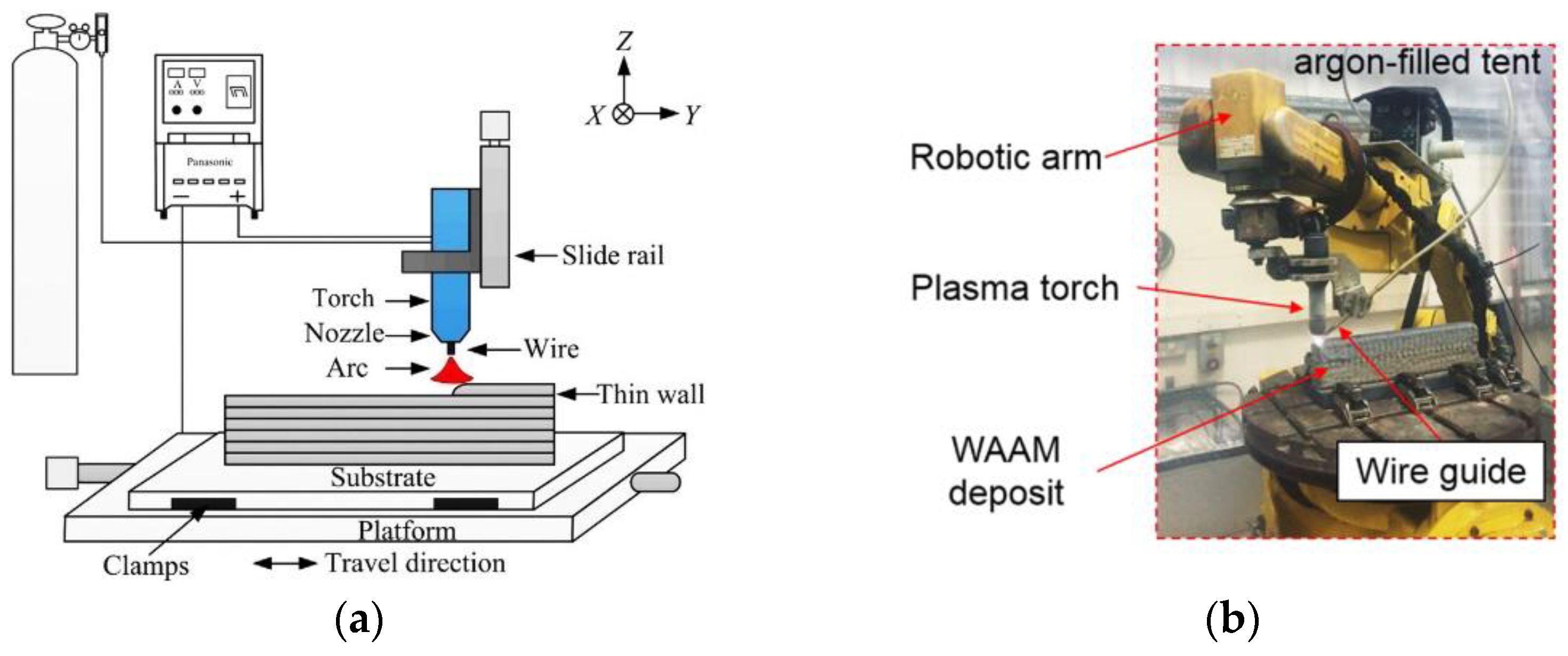
In this section, the use of WAAM in the deposition of a variety of wire metals is discussed, and an overview of the microstructures and the mechanical properties of the samples, such as micro-hardness, tensile test performance, and fracture test performance, is given. Figure 1 provides a schematic of WAAM equipment and an illustration of its installation. Due to the process’s high speed and environmental cooling, some defects are created in the additive samples [50]. However, AM parts with increased weight and volume have unique disadvantages, such as cracks and micro-cracks, incomplete process, porosity, and lack of adhesion of printed layers, which can be addressed by controlling and optimizing the hardware inputs and relevant parameters [51,52,53]. Additionally, some experiments have shown that complex process design for WAAM could be more precise, so it is hard to find topological optimization for this technique [54,55]. Carlos et al. studied numerical models for bending the parts created by WAAM. In this study, the horizontal links were considered for optimized geometries to achieve a better and stronger structure for the WAAM process [56].
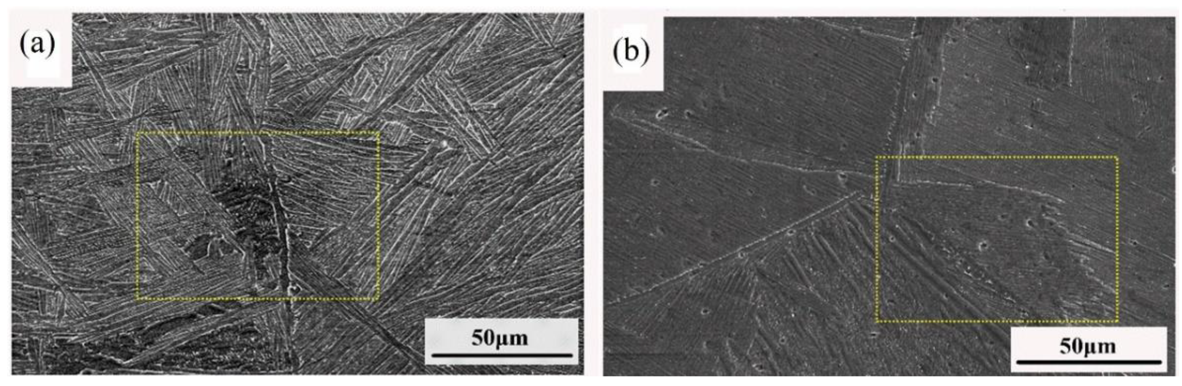
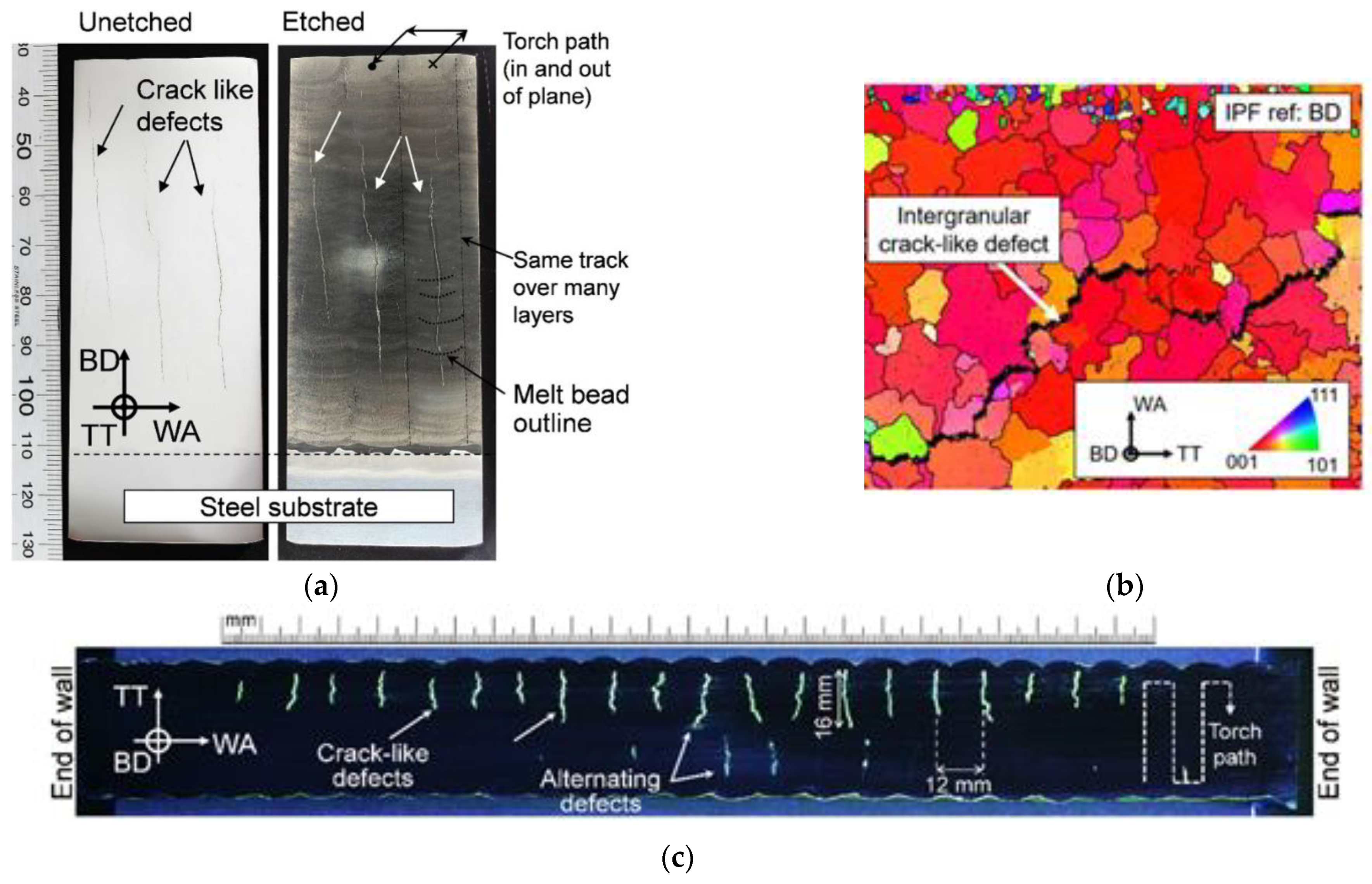
Figure 2a shows SEM images of a sample manufactured by WAAM, in which the wire was TC4-DT titanium alloy with a diameter of 0.6 mm [50]. After cooling the samples in the air and etching them with HF + 10% HNO3 + 86% H2O solution, some cracks were observed along the α’ structures (Figure 2b). One crucial factor to consider is the cooling process, as cooling the samples too quickly in the air can transfer heat into the surrounding layers, reducing the flexibility to form the proper shape. Figure 3a shows a crack created in 718 nickel-base alloy manufactured by the WAAM method [59]. The crack grew in the metal after the WAAM process and cooling in the air. Figure 3b shows the electron backscatter diffraction (EBSD) image of the cracks formed at the boundary of the layers. Figure 3c shows the surface microcracks of the sample where the lengths of some of the cracks reach 16 mm [58].
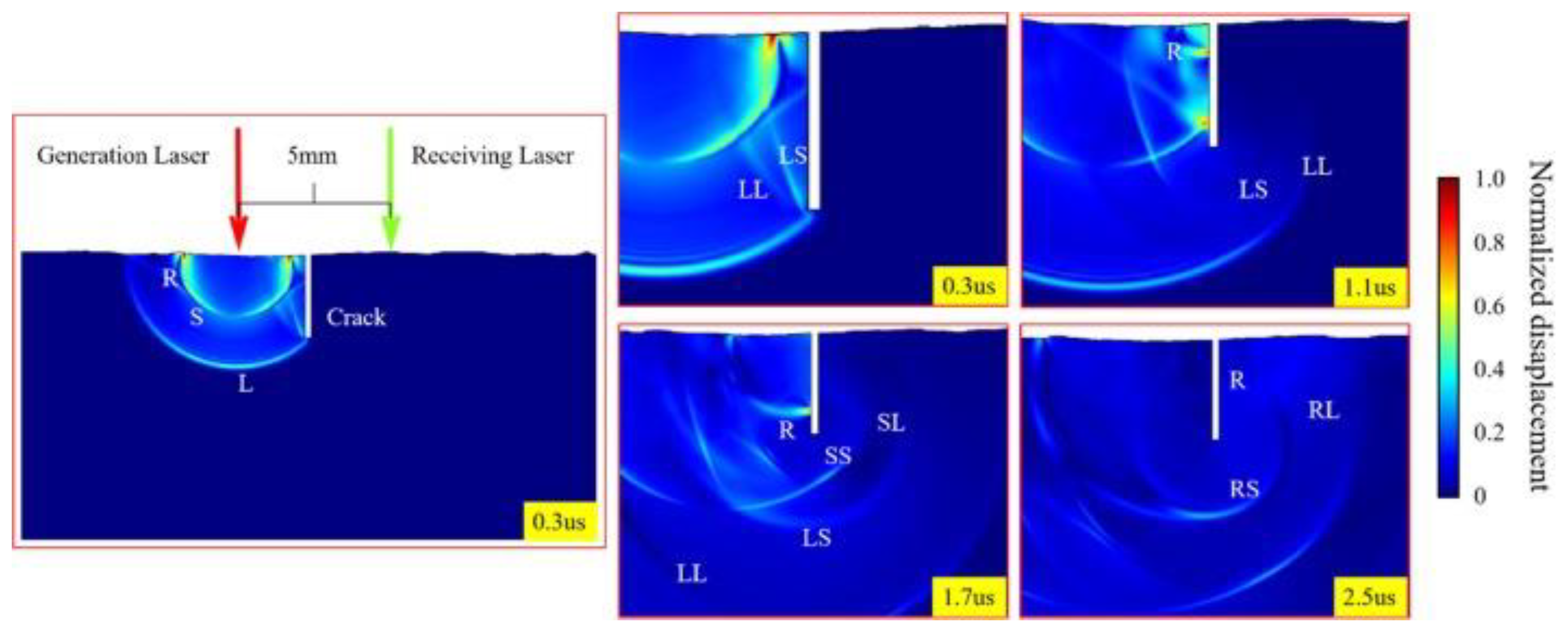
Figure 4 shows an example of detecting simulation using a non-destructive ultrasonic test (UT), which was evaluated by the finite element method with COMSOL software. This technique was used to find the surface cracks on the WAAM-deposited layers by calculating the response time of the R-wave, an acoustic velocity used for defect inspection, such as cracks. By comparing the reference signals with the L-wave and S-wave simulated amount, the ultrasonic change waves can be evaluated. When the signals are detected in the sample, revealing the RS and R waves can show the UT simulation of the cracks [60].
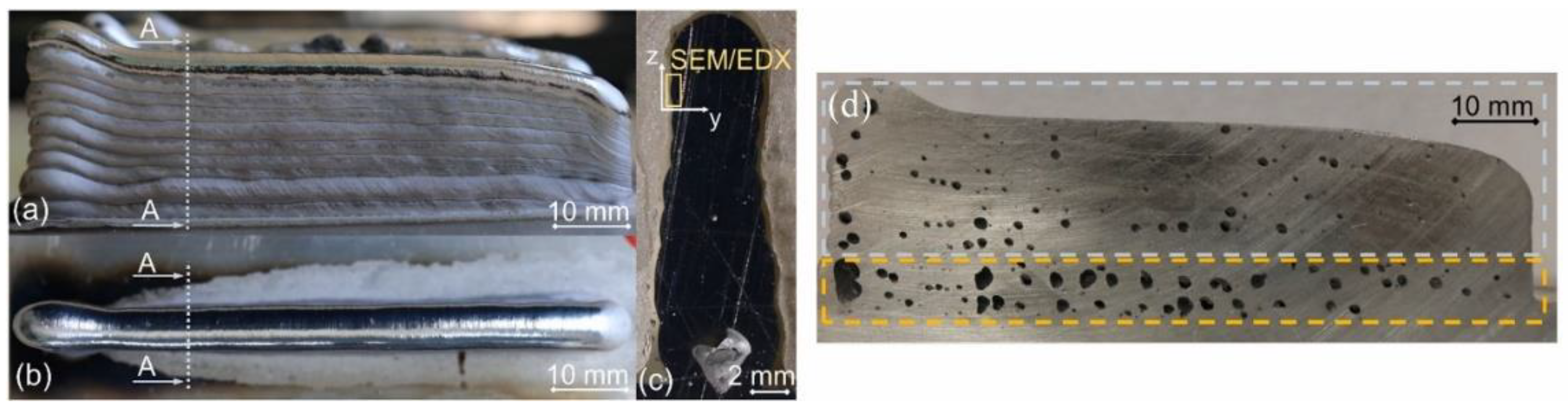
In an aluminum AM study [61], the relationship between the rate of shielding gas and the creation of porosity in the samples was investigated. The results showed that increasing the gas rate caused an increase in the value of the porosity of the pieces. This phenomenon happens because oxygen is trapped in the metal and in the melting pool when the rate of gas increases, which does not give the melt enough time to form uniformly. This results in the creation of porosity in certain areas (Figure 5) [61].
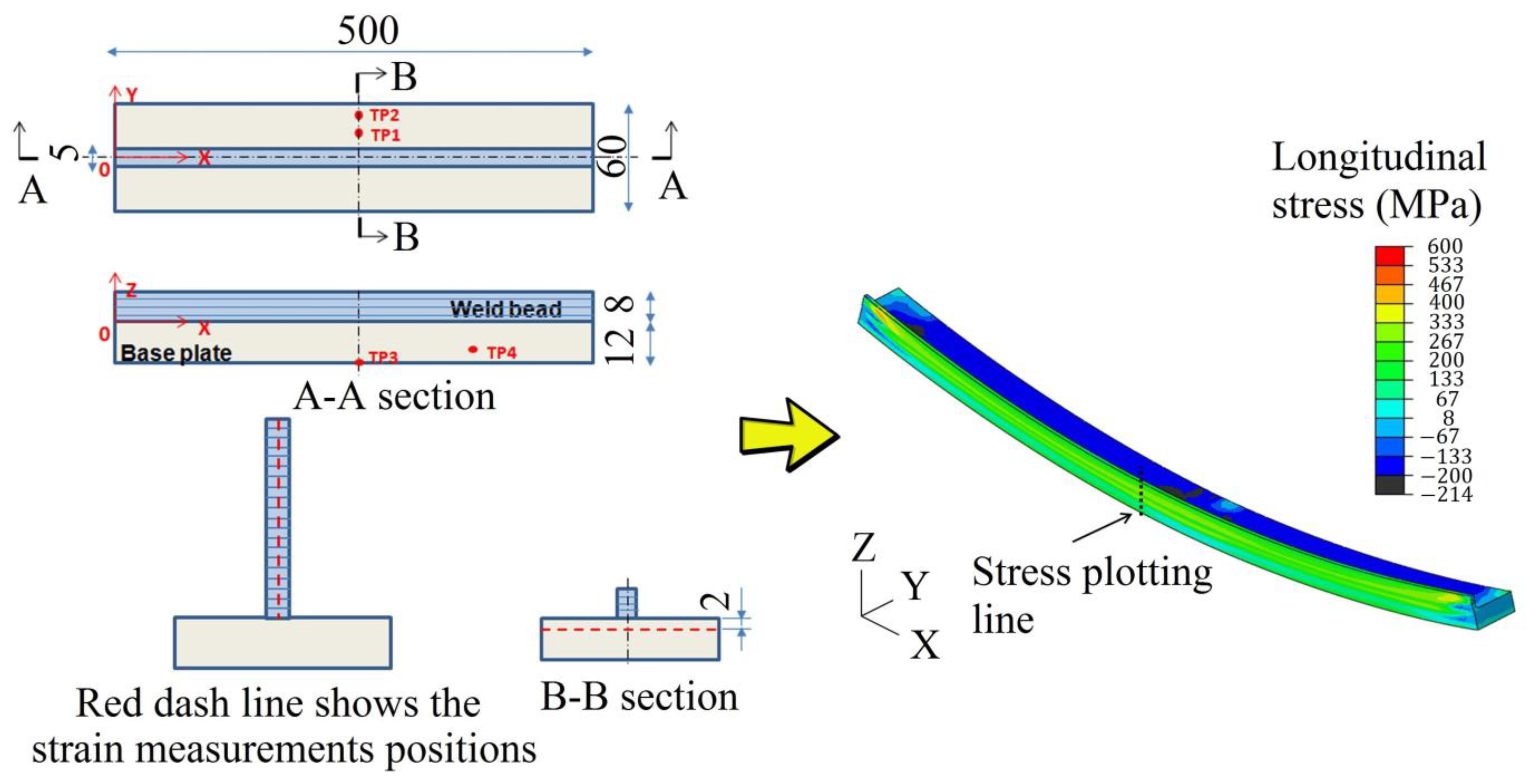
The systematic analysis of the aluminum alloy AlMg5Mn microstructure evolution during the WAAM process was the goal of the research paper by Gierth et al. [62]. The focus of the study was to analyze the impact of three different arc modes, namely cold metal transfer (CMT), CMT advanced (CMT-ADV), and CMT-pulse advanced (CMT-PADV), on various factors, such as the energy input per unit length, thermal cycles, final contour, microstructure, and mechanical-technological properties. The most appropriate arc mode should be chosen for the AM of high quality and large parts. The results showed that cracks occurred in the middle of the deposited lines beside the boundaries of the grain. UT and X-ray radiography can be used to inspect these defects. Variable symmetry and double-pulsed techniques were studied by Wang et al. [63] for GTAW welding of the aluminum alloy 2124. With a pronounced decrease in the coarse dendritic grains discovered by the traditional double-pulsed technique, and more uniform dispersion of the precipitations, the amount of refined equiaxed grains increased dramatically. In addition to the mentioned disadvantages, it is possible to point out the high capability of the WAAM process for producing samples with large dimensions and relatively good flexibility when using various diameters of metal wire to make the samples. These samples can be made using different metals. Table 1 shows recent studies that have used the WAAM method to make samples. The simulation of the WAAM process on the wall deposition of materials enables comparison with real experiments. Analysis of the mechanical properties and calculation of the strain measurement in three directions can use Hooke’s law (Equation (1)):
where εx, εy and εz are the strains in the three directions, and the elasticity and Poisson’s rate are E and υ, respectively. Applying this equation, the simulation can be more appropriate to the printed sample’s situation. In the Ding et al. [64] study, thermal analysis on mild steel was applied considering the strain measurement on the WAAM simulation (Figure 6). The cooling and heating cycles were predicted. Apart from the deposited line of the WAAM process, the stress is uniform; meanwhile, a considerable amount of stress can occur by unclamping.
In this regard, by changing the scanning strategies, Wang et al. [65] were able to produce printing patterns to make the WAAM samples with a lower roughness rate. Equation (2) was used:
where and are the average and absolute height of the surface points.
3. Wire Laser Additive Manufacturing (WLAM)
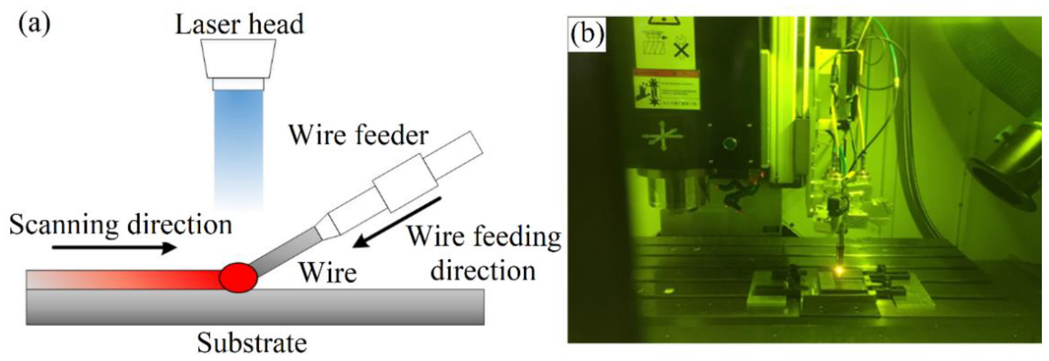
In this technique, the metal wires are melted with a laser beam and deposited in a line shape to create a sample with a complex geometry design (Figure 7).
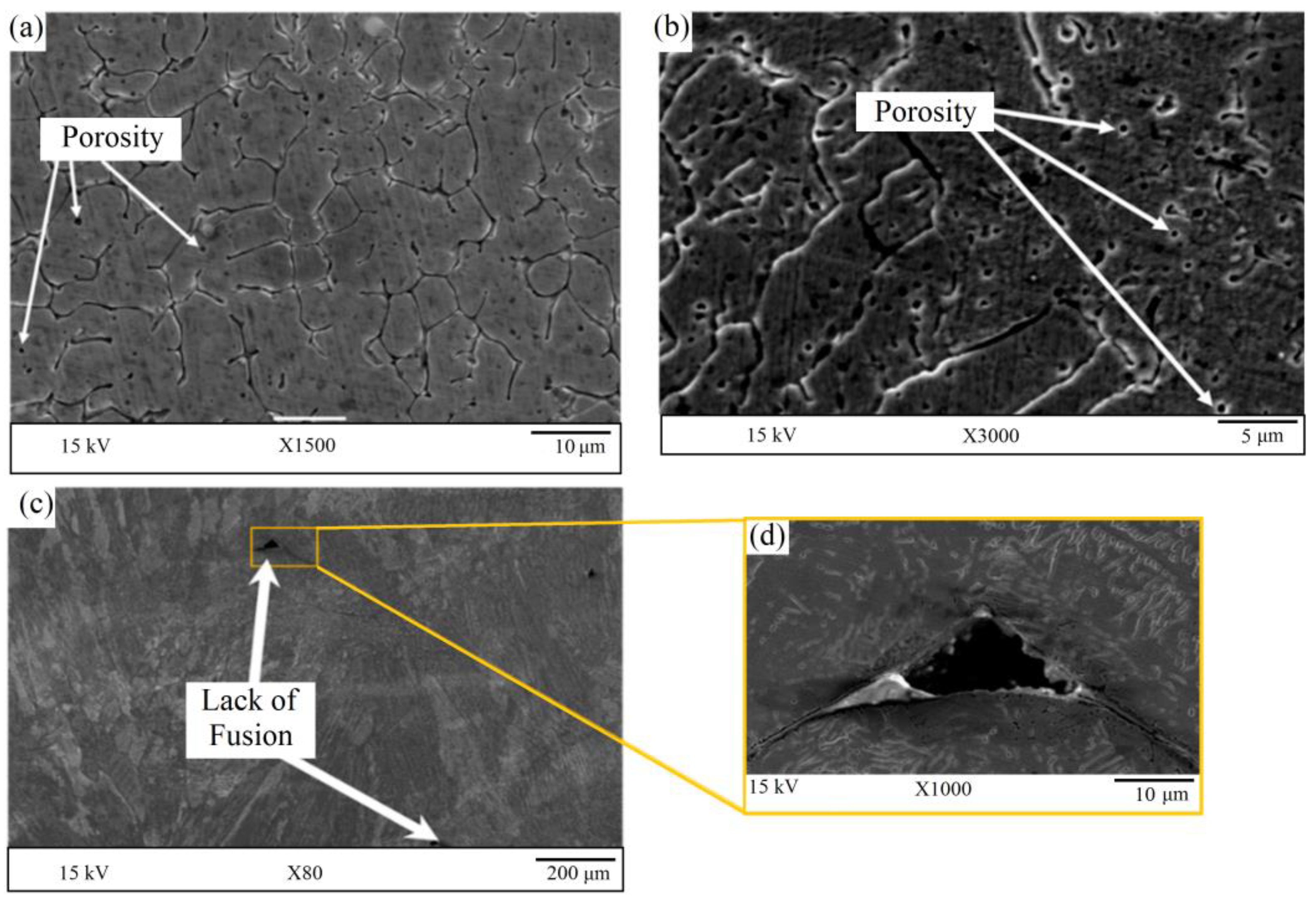
The patterns in this technique and the input laser parameters significantly influence the quality of the AM samples generated with no defects. However, defects can grow or generate during and after the WLAM process [81]. Regarding the high-speed WLAM process and melting of the metal wires, porosity can form in the samples [82,83,84,85,86,87,88]. In WLAM processes, austenite in some alloy steels is melted completely by high laser power. After passing the laser from the affected area, some martensite phase forms into the deposited layers. Thus, if the laser power increases, the melting pool has time to mix the austenite phase properly [89]. On the other hand, another effect of solidification for WLAM is generating porosity after backfilling the deposition. In this regard, the solidification rate in the melting pool is linked to laser speed and power; optimizing the WLAM parameters can reduce the level of porosity [90]. The environment air or shielding gases are trapped inside the AM structures and a range of porosities appear in the AM samples. Figure 8 shows the WLAM process of 316L stainless-steel wire, in which some porosities are formed during the process [91]. The high cooling rate during the wire arc additive manufacturing (WLAM) process results in porosities being trapped between the dendrite micro-structures of the 316L wire. This rapid cooling does not allow enough time for the austenite phase to properly form, leading to a mixture of ferrite and air trapped between the boundaries (Figure 8a,b). In addition, during the process, some porosities were reported in the 316L samples regarding the spaces between the deposited beads. This kind of porosity is widespread among the AM processes, so, in the deposited beads interaction section, some parts of the melted wire may not distribute properly because the last deposited beads usually have a non-uniform surface with waviness and with non-constant sections. In this situation, some parts of the samples are not covered by the melted metal after the WLAM process and a lack of fusion can happen in these samples (Figure 8c,d). The porosity of a material during laser fabrication can be influenced by various laser parameters, including the shielding gas. The optimal blowing distance and angle can help to ensure a steady flow rate during wire deposition, which, in turn, affects the molten pool. Therefore, the shielding gas parameters can have a significant impact on the overall quality of the material. Significant fluctuations in the shielding gas during laser fabrication can lead to the formation of porosities in the deposited layer [92]. This can happen due to disruptions in the stability of the molten pool. Table 2 provides a summary of recent studies related to wire and arc additive manufacturing (WLAM), including mechanical property tests and the types of lasers used.
4. Comparing WAAM and WLAM
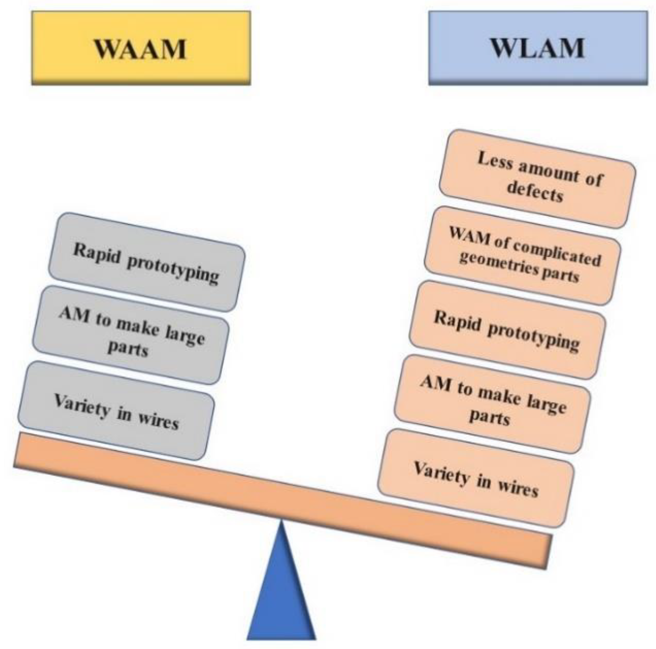
In this section, we discuss various aspects of additive manufacturing (AM) analysis for both wire and arc additive manufacturing (WAAM) and wire and laser additive manufacturing (WLAM) processes. One advantage of the WLAM process over WAAM is the small heat-affected area, which allows for more selective melting of the metal. However, the installation of optic equipment in the WLAM process can be challenging, making it difficult to install machine components. Additionally, due to the high cost of optic parts, such as lasers and laser heads, the WLAM process is generally more expensive to set up and maintain compared to WAAM. Compared to arc-based methods, the laser source in the WLAM process offers greater control over the heat input. As a result, the quality of the fabricated parts can be improved. Figure 9 provides a concise comparison of the advantages and disadvantages of WAAM and WLAM techniques.
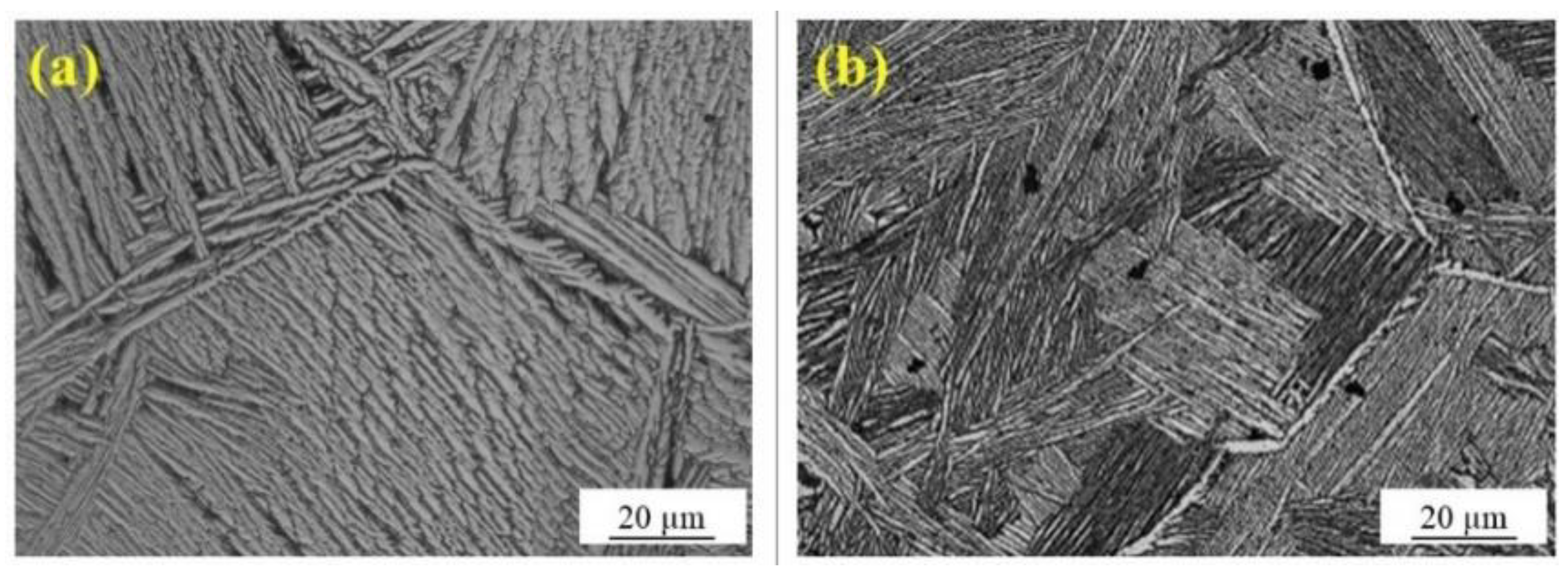
The WAAM technique can result in more manufacturing defects compared to WLAM. This is due to limitations in installing the arc system, which requires the wire to be deposited along simpler lines. If the complexity of the part increases, it can lead to incomplete processes or non-uniform walls, and an increase in overlapping walls. Figure 10 shows a comparison of the microstructures of the same material produced by WAAM and WLAM techniques [72,93]. In the microstructure images, the bright phase indicating the colony α in the boundary of β grains is more pronounced in the WLAM sample (Figure 10a) than in the WAAM sample (Figure 10b). Furthermore, the β grains in the WLAM sample are more uniformly distributed.
5. Laser Arc Hybrid Wire Manufacturing (LAHWM)
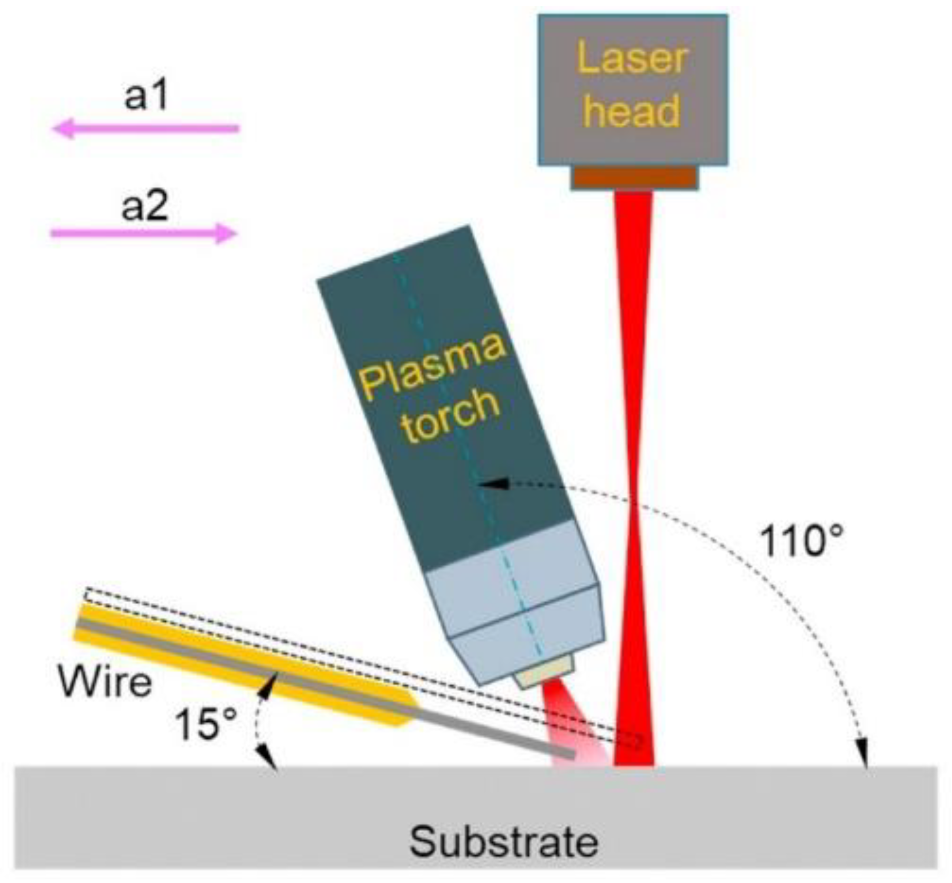
Laser arc hybrid wire manufacturing (LAHWM) is a hybrid manufacturing process that combines wire arc manufacturing (WAM) and laser manufacturing (LM) processes. In Figure 11 are depicted a scheme of the process, where a1 represent the arc leader configuration, and a2 the laser leader configuration. In this approach, a laser is used to melt the wire feedstock. In contrast, an arc is used to stabilize the melt pool, resulting in a higher deposition rate, improved surface quality, and better mechanical properties [108].
LAHWM has been used to fabricate various metallic parts for aerospace, automotive, and biomedical applications [109]. It can be used with many materials, including aluminum, titanium, and stainless steel. It can produce parts with high precision, high surface quality, and good mechanical properties. The advantages of LAHWM include [110]:
- High deposition rate: The high deposition rate of LAHWM enables the production of large and complex parts in a relatively short time.
- Cost-effectiveness: LAHWM is a cost-effective method for producing large parts as it requires less material compared to powder-based additive manufacturing.
- High precision: LAHWM produces parts with high precision and surface quality due to the high energy density of the laser and arc.
- Versatility: LAHWM can be used with a wide range of materials, including aluminum, titanium, and stainless steel.
- Improved mechanical properties: LAHWM can produce parts with improved mechanical properties, such as high strength and toughness.
However, LAHWM is still under development and research, and still faces some challenges, such as the need for further research to improve the quality of the deposited material and the need to develop post-processing techniques to improve the mechanical properties of the manufactured parts [111]. Overall, LAHWM is a promising technology that can produce high-quality parts cost-effectively and efficiently. With continued development and research, LAHWM is expected to play an increasingly important role in various industries in the future [112]. To overcome the limitations of both WAAM and WLAM, the LAHWM technique was developed to enhance the operation of the process. WAAM faces challenges in the fabrication of complex parts due to the limitations of the arc and process parameters. On the other hand, the LAHWM technique can achieve the highest deposition rate by using two or more wire feeders, making it a more feasible option [111]. Based on research, the rate of porosity decreases significantly by comparison with WAAM processes. In some cases, the amount of porosity decreased by 70% using the LAHWM method [113]. A summary of recent articles is show in Table 3, the used metal are highlighted.
6. Comparison between WAAM, WLAM and WLAHM
WAAM, WLAM, and WLAHM all have their advantages and disadvantages. In summary, WAAM is a cost-effective process with low precision and poor surface quality, WLAM is a high-precision and high-speed process but with high cost, and WLAHM is a high-efficiency and high-precision process with high cost and complexity [117,118]. WLAHM is considered the most versatile process among the three but involves the most complex process. WAAM is the most cost-effective process but has the lowest precision, while WLAM is the most precise and expensive process [119]. The choice of which process to use will depend on the specific application and the desired balance of cost, precision, and surface quality [120]. Table 4 provides an at-a-glance comparison of WAAM, WLAM, and WLAHM processes by considering three ranks, -, +, and ++, representing low, middle and high effectiveness, respectively. WLAHM has some disadvantageous aspects, such as the procedure for installation taking more time. Moreover, with this technique, more devices are involved in the process compared to WAAM and WLAM processes; the positives responses are outweighed by these disadvantages [114]. One of the distinctive features of WLAHM is that it can use two lasers simultaneously to make the process more effective. By using thicker metal wire in this technique, large parts can be manufactured faster, and the accuracy of the melting pool can increase dramatically [108]. The laser process keyhole can shape better when two lasers are applied in WLAHM, and the bead of the deposited layers has a suitable appliance so that the other layers can deposit on each other very uniformly [108,110]. Moreover, regarding the equipment components of the three WAM methods, WAAM has fewer parts than WLAM and WLAHM. Additionally, WLAM and WLAHM have optical elements that can be damaged, so the portability of WAAM is easier than the laser components [109].
Moreover, WAAM is known for its high deposition rate, low cost, and flexibility in use of materials, but exhibits low precision and poor surface quality. WLAM is known for its high accuracy and speed but has high costs and limited flexibility in terms of materials. WLAHM is known for its high precision, high efficiency, good surface quality, and flexibility in terms of materials, but it has high costs and complexity. In the WAM process, the laser and arc can melt wire properly. WLAM or WAAM can be applied depending on the environmental conditions, the metal types, the process speed, the sample volume, the budget, and other influential factors. One of the limitations of the WLAM process is the use of reflective metals because the laser beam may be reflected and damage the laser source. However, the high capability of the WLAM process for making complex parts with unique geometries can advance MWAM processes by several steps.
7. Outlook in MWAM Research and Development
Extending the framework for predicting other properties which result from the deposited layers in multilayer printing is very challenging because the WAM technique has only been developed for a couple of years and a comprehensive overview of the mechanical properties of the AM samples needs extensive work. The created framework enables real-time estimation of printed items’ microstructural characteristics, or provision of a direct comparison with the specified microstructural features between WAM techniques. To obtain the desired microstructure in the WAM process it is necessary to adjust the process parameters in a closed-loop feedback manner by organizing the desired and estimated microstructural properties.
Monitoring the microstructure of multi-material WAM is an exciting area of research, with closed-loop feedback on molten pool monitoring after cooling or during the process contributing to better understanding of the transformation of the microstructure phases [16]. Studies undertaken on the microstructures and grain size of the manufactured samples show that the controlling heat input of the melting pool has a direct effect on the quality of microstructures because it is necessary to reach uniform temperatures in the melting pool. This phenomenon can help to reduce the chance of defect generation after the cooling process for each layer. It should be noted that monitoring the metal melting areas and analyzing the images and videos taken by high-speed cameras can lead to a correct understanding of how the metal melts. This data can be utilized for image processing in the WAM process, thereby aiding future research to advance the machine learning components. One of the most critical zones in the WAM process is the melting pool caused by the wire that forms the layers. In this zone, some defects may occur during and after the WAM process due to the high speed of the process and the small distance of the heat-affected zone from the laser process. Monitoring with thermo-cameras and installing thermal sensors make it possible to record the data resulting from the heat generated. Wires with small diameters can be operated in the WAM process in the tissue-engineering process, which controls the process more accurately and uses metals such as magnesium alloys, which can be very useful in many medical areas and in bioengineering. This unique application can even be used to repair or fix defects in damaged structures that have been in human or animal bodies, and there is no need to remove and replace parts by selecting proper methods to print these parts. The samples are placed in the bodies, and the WAM effectively reduces incidental costs with respect to medical aspects. In addition to the applications discussed earlier for WAM techniques, they can also be used in the electronics industry for welding the bases of sensitive parts and creating thin lines on boards by melting metal wires. Among the WAM techniques, WAAM is considered the most suitable technique for load-bearing and precision engineering, as well as for strengthening and repair purposes.
8. Conclusions
In conclusion, WAM is a rapidly evolving technology that has the potential to revolutionize the way metal parts are manufactured in several industries. WAAM, WLAM, and WLAHM are the three main MWAM processes, each with unique advantages and disadvantages.
To achieve better microstructural properties, dimensional accuracy, and surface quality in MWAM, it is essential to identify the main process parameters and deposition strategies that influence the macroscopic properties and geometrical accuracy of different arc and laser processes. Further research is needed to fully exploit the potential of these processes in aerospace, automotive, biomedical, and energy fields, amongst others.
In order to promote the adoption and development of MWAM, it is crucial to develop a decision-making model that takes into account the most important factors for different industry sectors to help them determine which MWAM technique is best suited for their specific needs. Moreover, the establishment of common technical standards for metal WAAM would be a valuable initiative to ensure the consistency and repeatability of metal prints.
Author Contributions
Material preparation, data collection and analysis were performed by all authors. All authors have read and agreed to the published version of the manuscript.
Funding
Financed by the European Union—NextGenerationEU (National Sustainable Mobility Center CN00000023, Italian Ministry of University and Research Decree n. 1033-17/06/2022, Spoke 11—Innovative Materials & Lightweighting). The opinions expressed are those of the authors only and should not be considered as representative of the European Union or the European Commission’s official position. Neither the European Union nor the European Commission can be held responsible for them. (grant no. CUP-D93C22000410001).
Data Availability Statement
Not applicable.
Conflicts of Interest
The authors declare that they have no known competing financial interests or personal relationships that could have appeared to influence the work reported in this paper.
References
- Wong, K.V.; Hernandez, A. A Review of Additive Manufacturing. ISRN Mech. Eng. 2012, 16, 208760. [Google Scholar] [CrossRef] [Green Version]
- Gibson, I.; Rosen, D.; Stucker, B.; Khorasani, M. Materials for Additive Manufacturing. In Additive Manufacturing Technologies; Springer International Publishing: Cham, Switzerland, 2021; pp. 379–428. [Google Scholar]
- Sahafnejad-Mohammadi, I.; Karamimoghadam, M.; Zolfagharian, A.; Akrami, M.; Bodaghi, M. 4D printing technology in medical engineering: A narrative review. J. Braz. Soc. Mech. Sci. Eng. 2022, 44, 233. [Google Scholar] [CrossRef]
- Dilberoglu, U.M.; Gharehpapagh, B.; Yaman, U.; Dolen, M. The Role of Additive Manufacturing in the Era of Industry 4.0. Procedia Manuf. 2017, 11, 545–554. [Google Scholar] [CrossRef]
- Vayre, B.; Vignat, F.; Villeneuve, F. Designing for Additive Manufacturing. Procedia CIRP 2012, 3, 632–637. [Google Scholar] [CrossRef] [Green Version]
- Williams, S.W.; Martina, F.; Addison, A.C.; Ding, J.; Pardal, G.; Colegrove, P. Wire + Arc Additive Manufacturing. Mater. Sci. Technol. 2016, 32, 641–647. [Google Scholar] [CrossRef] [Green Version]
- Herzog, D.; Seyda, V.; Wycisk, E.; Emmelmann, C. Additive manufacturing of metals. Acta Mater. 2016, 117, 371–392. [Google Scholar] [CrossRef]
- Bourell, D.; Kruth, J.P.; Leu, M.; Levy, G.; Rosen, D.; Beese, A.M.; Clare, A. Materials for additive manufacturing. CIRP Ann. 2017, 66, 659–681. [Google Scholar] [CrossRef]
- Wohlers, T.; Gornet, T. History of Additive Manufacturing; Wohlers Associates: Fort Collins, CO, USA; Washington, DC, USA, 2016. [Google Scholar]
- Gao, W.; Zhang, Y.; Ramanujan, D.; Ramani, K.; Chen, Y.; Williams, C.B.; Wang, C.C.L.; Shin, Y.C.; Zhang, S.; Zavattieri, P.D. The status, challenges, and future of additive manufacturing in engineering. Comput.-Aided Des. 2015, 69, 65–89. [Google Scholar] [CrossRef]
- Guo, N.; Leu, M.C. Additive manufacturing: Technology, applications and research needs. Front. Mech. Eng. 2013, 8, 215–243. [Google Scholar] [CrossRef]
- Bikas, H.; Stavropoulos, P.; Chryssolouris, G. Additive manufacturing methods and modelling approaches: A critical review. Int. J. Adv. Manuf. Technol. 2015, 83, 389–405. [Google Scholar] [CrossRef] [Green Version]
- Horn, T.J.; Harrysson, O.L.A. Overview of Current Additive Manufacturing Technologies and Selected Applications. Sci. Prog. 2012, 95, 255–282. [Google Scholar] [CrossRef]
- Calignano, F.; Manfredi, D.; Ambrosio, E.P.; Biamino, S.; Lombardi, M.; Atzeni, E.; Salmi, A.; Minetola, P.; Iuliano, L.; Fino, P. Overview on Additive Manufacturing Technologies. Proc. IEEE 2017, 105, 593–612. [Google Scholar] [CrossRef]
- Altıparmak, S.C.; Xiao, B. A market assessment of additive manufacturing potential for the aerospace industry. J. Manuf. Process. 2021, 68, 728–738. [Google Scholar] [CrossRef]
- Ekren, B.Y.; Stylos, N.; Zwiegelaar, J.; Turhanlar, E.E.; Kumar, V. Additive manufacturing integration in E-commerce supply chain network to improve resilience and competitiveness. Simul. Model. Pract. Theory 2023, 122, 102676. [Google Scholar] [CrossRef]
- Abdulhameed, O.; Al-Ahmari, A.; Ameen, W.; Mian, S.H. Additive manufacturing: Challenges, trends, and applications. Adv. Mech. Eng. 2019, 11, 168781401882288. [Google Scholar] [CrossRef] [Green Version]
- Gibson, I.; Rosen, D.; Stucker, B.; Khorasani, M. Design for Additive Manufacturing. In Additive Manufacturing Technologies; Springer International Publishing: Cham, Switzerland, 2021; pp. 555–607. [Google Scholar]
- Prakash, K.S.; Nancharaih, T.; Rao, V.S. Additive Manufacturing Techniques in Manufacturing -An Overview. Mater. Today Proc. 2018, 5, 3873–3882. [Google Scholar] [CrossRef]
- Ford, S.; Despeisse, M. Additive manufacturing and sustainability: An exploratory study of the advantages and challenges. J. Clean. Prod. 2016, 137, 1573–1587. [Google Scholar] [CrossRef]
- Meiabadi, M.S.; Moradi, M.; Karamimoghadam, M.; Ardabili, S.; Bodaghi, M.; Shokri, M.; Mosavi, A.H. Modeling the Producibility of 3D Printing in Polylactic Acid Using Artificial Neural Networks and Fused Filament Fabrication. Polymers 2021, 13, 3219. [Google Scholar] [CrossRef]
- Huang, S.H.; Liu, P.; Mokasdar, A.; Hou, L. Additive manufacturing and its societal impact: A literature review. Int. J. Adv. Manuf. Technol. 2013, 67, 1191–1203. [Google Scholar] [CrossRef]
- Scott, J.; Gupta, N.; Weber, C.; Caffrey, T. Additive Manufacturing: Status and Opportunities; Science and Technology Policy Institute: Washington, DC, USA, 2012. [Google Scholar]
- Bourell, D.L. Perspectives on Additive Manufacturing. Annu. Rev. Mater. Res. 2016, 46, 1–18. [Google Scholar] [CrossRef]
- Jiang, J.; Xu, X.; Stringer, J. Support Structures for Additive Manufacturing: A Review. J. Manuf. Mater. Process. 2018, 2, 64. [Google Scholar] [CrossRef] [Green Version]
- Kruth, J.-P.; Leu, M.C.; Nakagawa, T. Progress in Additive Manufacturing and Rapid Prototyping. Cirp Ann. 1998, 47, 525–540. [Google Scholar] [CrossRef]
- Gibson, I.; Rosen, D.; Stucker, B.; Khorasani, M. Development of Additive Manufacturing Technology. In Additive Manufacturing Technologies; Springer International Publishing: Cham, Switzerland, 2021; pp. 23–51. [Google Scholar]
- Gu, D. Laser Additive Manufacturing (AM): Classification, Processing Philosophy, and Metallurgical Mechanisms. In Laser Additive Manufacturing of High-Performance Materials; Springer: Berlin/Heidelberg, Germany, 2015; pp. 15–71. [Google Scholar]
- Caiazzo, F.; Alfieri, V.; Casalino, G. On the Relevance of volumetric energy density in the investigation of inconel 718 laser powder bed fusion. Materials 2020, 13, 538. [Google Scholar] [CrossRef] [Green Version]
- Jiménez, A.; Bidare, P.; Hassanin, H.; Tarlochan, F.; Dimov, S.; Essa, K. Powder-based laser hybrid additive manufacturing of metals: A review. Int. J. Adv. Manuf. Technol. 2021, 114, 63–96. [Google Scholar] [CrossRef]
- Seepersad, C.C. Challenges and Opportunities in Design for Additive Manufacturing. 3D Print. Addit. Manuf. 2014, 1, 10–13. [Google Scholar] [CrossRef]
- Errico, V.; Campanelli, S.L.; Angelastro, A.; Mazzarisi, M.; Casalino, G. On the feasibility of AISI 304 stainless steel laser welding with metal powder. J. Manuf. Process. 2020, 56, 96–105. [Google Scholar] [CrossRef]
- Gasser, A.; Backes, G.; Kelbassa, I.; Weisheit, A.; Wissenbach, K. Laser Additive Manufacturing. Laser Tech. J. 2010, 7, 58–63. [Google Scholar] [CrossRef]
- Boley, C.D.; Khairallah, S.A.; Rubenchik, A.M. Calculation of laser absorption by metal powders in additive manufacturing. Appl. Opt. 2015, 54, 2477. [Google Scholar] [CrossRef]
- Bär, F.; Berger, L.; Jauer, L.; Kurtuldu, G.; Schäublin, R.; Schleifenbaum, J.H.; Löffler, J.F. Laser additive manufacturing of biodegradable magnesium alloy WE43: A detailed microstructure analysis. Acta Biomater. 2019, 98, 36–49. [Google Scholar] [CrossRef]
- Rajaguru, K.; Karthikeyan, T.; Vijayan, V. Additive manufacturing—State of art. Mater. Today Proc. 2020, 21, 628–633. [Google Scholar] [CrossRef]
- Doubrovski, Z.; Verlinden, J.C.; Geraedts, J.M.P. Optimal Design for Additive Manufacturing: Opportunities and Challenges. In Proceedings of the Volume 9: 23rd International Conference on Design Theory and Methodology; 16th Design for Manufacturing and the Life Cycle Conference, Washington, DC, USA, 28–31 August 2011; ASMEDC: Washington, DC, USA, 2011; pp. 635–646. [Google Scholar]
- Hu, D.; Kovacevic, R. Sensing, modeling and control for laser-based additive manufacturing. Int. J. Mach. Tools Manuf. 2003, 43, 51–60. [Google Scholar] [CrossRef]
- Moradi, M.; Karami Moghadam, M.; Asgari, F. 4D Printing Additive Manufacturing Review: Mechanisim, Chalanges, Applications and Future. Modares Mech. Eng. 2020, 20, 1063–1077. [Google Scholar]
- Slotwinski, J.A.; Garboczi, E.J.; Stutzman, P.E.; Ferraris, C.F.; Watson, S.S.; Peltz, M.A. Characterization of Metal Powders Used for Additive Manufacturing. J. Res. Natl. Inst. Stand. Technol. 2014, 119, 460–493. [Google Scholar] [CrossRef]
- Lakhdar, Y.; Tuck, C.; Binner, J.; Terry, A.; Goodridge, R. Additive manufacturing of advanced ceramic materials. Prog. Mater. Sci. 2020, 116, 100736. [Google Scholar] [CrossRef]
- Durakovic, B. Design for additive manufacturing: Benefits, trends and challenges. Period. Eng. Nat. Sci. (PEN) 2018, 6, 179. [Google Scholar] [CrossRef] [Green Version]
- Bhuvanesh Kumar, M.; Sathiya, P. Methods and materials for additive manufacturing: A critical review on advancements and challenges. Thin-Walled Struct. 2021, 159, 107228. [Google Scholar] [CrossRef]
- Yadav, S.P.; Pawade, R.S. Manufacturing Methods Induced Property Variations in Ti6Al4V Using High-Speed Machining and Additive Manufacturing (AM). Metals 2023, 13, 287. [Google Scholar] [CrossRef]
- Alonso, U.; Veiga, F.; Suárez, A.; Gil Del Val, A. Characterization of Inconel 718® superalloy fabricated by wire Arc Additive Manufacturing: Effect on mechanical properties and machinability. J. Mater. Res. Technol. 2021, 14, 2665–2676. [Google Scholar] [CrossRef]
- Safavi, M.S.; Bordbar-Khiabani, A.; Khalil-Allafi, J.; Mozafari, M.; Visai, L. Additive Manufacturing: An Opportunity for the Fabrication of Near-Net-Shape NiTi Implants. J. Manuf. Mater. Process. 2022, 6, 65. [Google Scholar] [CrossRef]
- Frazier, W.E. Metal Additive Manufacturing: A Review. J. Mater. Eng. Perform 2014, 23, 1917–1928. [Google Scholar] [CrossRef]
- Safavi, M.S.; Azarniya, A.; Farshbaf Ahmadipour, M.; Reddy, M.V. New-emerging approach for fabrication of near net shape aluminum matrix composites/nanocomposites: Ultrasonic additive manufacturing. J. Ultrafine Grained Nanostruct. Mater. 2019, 52, 188–196. [Google Scholar]
- Singh, S.; Ramakrishna, S.; Singh, R. Material issues in additive manufacturing: A review. J. Manuf. Process. 2017, 25, 185–200. [Google Scholar] [CrossRef]
- Gao, Y.; Wu, C.; Peng, K.; Song, X.; Fu, Y.; Chen, Q.; Zhang, M.; Wang, G.; Liu, J. Towards superior fatigue crack growth resistance of TC4-DT alloy by in-situ rolled wire-arc additive manufacturing. J. Mater. Res. Technol. 2021, 15, 1395–1407. [Google Scholar] [CrossRef]
- Dharmendra, C.; Shakerin, S.; Ram, G.D.J.; Mohammadi, M. Wire-arc additive manufacturing of nickel aluminum bronze/stainless steel hybrid parts—Interfacial characterization, prospects, and problems. Materialia 2020, 13, 100834. [Google Scholar] [CrossRef]
- Liu, R.; Wang, Z.; Sparks, T.; Liou, F.; Newkirk, J. Aerospace applications of laser additive manufacturing. In Laser Additive Manufacturing; Elsevier: Amsterdam, The Netherlands, 2017; pp. 351–371. [Google Scholar]
- Froes, F.H.; Boyer, R. (Eds.) Additive Manufacturing for the Aerospace Industry; Elsevier: Amsterdam, The Netherlands, 2019. [Google Scholar]
- Veiga, F.; Suárez, A.; Aldalur, E.; Goenaga, I.; Amondarain, J. Wire Arc Additive Manufacturing Process for Topologically Optimized Aeronautical Fixtures. 3D Print. Addit. Manuf. 2023, 10, 23–33. [Google Scholar] [CrossRef]
- Zhang, H.; Huang, J.; Liu, C.; Ma, Y.; Han, Y.; Xu, T.; Lu, J.; Fang, H. Fabricating Pyramidal Lattice Structures of 304 L Stainless Steel by Wire Arc Additive Manufacturing. Materials 2020, 13, 3482. [Google Scholar] [CrossRef] [PubMed]
- Ramonell, C.; Chacón, R. On the topological optimization of horizontal links in eccentrically braced frames. J. Constr. Steel Res. 2021, 185, 106887. [Google Scholar] [CrossRef]
- Alagha, A.N.; Hussain, S.; Zaki, W. Additive manufacturing of shape memory alloys: A review with emphasis on powder bed systems. Mater. Des. 2021, 204, 109654. [Google Scholar] [CrossRef]
- Seow, C.E.; Zhang, J.; Coules, H.E.; Wu, G.; Jones, C.; Ding, J.; Williams, S. Effect of crack-like defects on the fracture behaviour of Wire + Arc Additively Manufactured nickel-base Alloy 718. Addit. Manuf. 2020, 36, 101578. [Google Scholar] [CrossRef]
- Pereira, T.; Kennedy, J.V.; Potgieter, J. A comparison of traditional manufacturing vs additive manufacturing, the best method for the job. Procedia Manuf. 2019, 30, 11–18. [Google Scholar] [CrossRef]
- Zeng, Y.; Wang, X.; Qin, X.; Hua, L.; Xu, M. Laser Ultrasonic inspection of a Wire + Arc Additive Manufactured (WAAM) sample with artificial defects. Ultrasonics 2021, 110, 106273. [Google Scholar] [CrossRef] [PubMed]
- Hauser, T.; Reisch, R.T.; Breese, P.P.; Lutz, B.S.; Pantano, M.; Nalam, Y.; Bela, K.; Kamps, T.; Volpp, J.; Kaplan, A.F. Porosity in wire arc additive manufacturing of aluminium alloys. Addit. Manuf. 2021, 41, 101993. [Google Scholar] [CrossRef]
- Gierth, M.; Henckell, P.; Ali, Y.; Scholl, J.; Bergmann, J.P. Wire Arc Additive Manufacturing (WAAM) of Aluminum Alloy AlMg5Mn with Energy-Reduced Gas Metal Arc Welding (GMAW). Materials 2020, 13, 2671. [Google Scholar] [CrossRef] [PubMed]
- Wang, Y.; Qi, B.; Cong, B.; Yang, M.; Liu, F. Arc characteristics in double-pulsed VP-GTAW for aluminum alloy. J. Mater. Process. Technol. 2017, 249, 89–95. [Google Scholar] [CrossRef]
- Ding, J.; Colegrove, P.; Mehnen, J.; Ganguly, S.; Almeida, P.S.; Wang, F.; Williams, S. Thermo-mechanical analysis of Wire and Arc Additive Layer Manufacturing process on large multi-layer parts. Comput. Mater. Sci. 2011, 50, 3315–3322. [Google Scholar] [CrossRef] [Green Version]
- Wang, F.; Williams, S.; Colegrove, P.; Antonysamy, A.A. Microstructure and Mechanical Properties of Wire and Arc Additive Manufactured Ti-6Al-4V. Met. Mater. Trans. A 2012, 44, 968–977. [Google Scholar] [CrossRef]
- Ding, D.; Pan, Z.; Cuiuri, D.; Li, H. A tool-path generation strategy for wire and arc additive manufacturing. Int. J. Adv. Manuf. Technol. 2014, 73, 173–183. [Google Scholar] [CrossRef] [Green Version]
- Shen, C.; Pan, Z.; Ma, Y.; Cuiuri, D.; Li, H. Fabrication of iron-rich Fe–Al intermetallics using the wire-arc additive manufacturing process. Addit. Manuf. 2015, 7, 20–26. [Google Scholar] [CrossRef]
- Ding, D.; Pan, Z.; van Duin, S.; Li, H.; Shen, C. Fabricating Superior NiAl Bronze Components through Wire Arc Additive Manufacturing. Materials 2016, 9, 652. [Google Scholar] [CrossRef] [Green Version]
- Dong, B.; Pan, Z.; Shen, C.; Ma, Y.; Li, H. Fabrication of Copper-Rich Cu-Al Alloy Using the Wire-Arc Additive Manufacturing Process. Met. Mater. Trans. B 2017, 48, 3143–3151. [Google Scholar] [CrossRef]
- Ge, J.; Lin, J.; Chen, Y.; Lei, Y.; Fu, H. Characterization of wire arc additive manufacturing 2Cr13 part: Process stability, microstructural evolution, and tensile properties. J. Alloys Compd. 2018, 748, 911–921. [Google Scholar] [CrossRef]
- Graf, M.; Hälsig, A.; Höfer, K.; Awiszus, B.; Mayr, P. Thermo-Mechanical Modelling of Wire-Arc Additive Manufacturing (WAAM) of Semi-Finished Products. Metals 2018, 8, 1009. [Google Scholar] [CrossRef] [Green Version]
- Wu, B.; Pan, Z.; Ding, D.; Cuiuri, D.; Li, H. Effects of heat accumulation on microstructure and mechanical properties of Ti6Al4V alloy deposited by wire arc additive manufacturing. Addit. Manuf. 2018, 23, 151–160. [Google Scholar] [CrossRef]
- Oyama, K.; Diplas, S.; M’Hamdi, M.; Gunnæs, A.E.; Azar, A.S. Heat source management in wire-arc additive manufacturing process for Al-Mg and Al-Si alloys. Addit. Manuf. 2019, 26, 180–192. [Google Scholar] [CrossRef]
- Yangfan, W.; Xizhang, C.; Chuanchu, S. Microstructure and mechanical properties of Inconel 625 fabricated by wire-arc additive manufacturing. Surf. Coatings Technol. 2019, 374, 116–123. [Google Scholar] [CrossRef]
- Bambach, M.; Sizova, I.; Sydow, B.; Hemes, S.; Meiners, F. Hybrid manufacturing of components from Ti-6Al-4V by metal forming and wire-arc additive manufacturing. J. Mater. Process. Technol. 2020, 282, 116689. [Google Scholar] [CrossRef]
- Dong, B.; Cai, X.; Lin, S.; Li, X.; Fan, C.; Yang, C.; Sun, H. Wire arc additive manufacturing of Al-Zn-Mg-Cu alloy: Microstructures and mechanical properties. Addit. Manuf. 2020, 36, 101447. [Google Scholar] [CrossRef]
- Suárez, A.; Aldalur, E.; Veiga, F.; Artaza, T.; Tabernero, I.; Lamikiz, A. Wire arc additive manufacturing of an aeronautic fitting with different metal alloys: From the design to the part. J. Manuf. Process. 2021, 64, 188–197. [Google Scholar] [CrossRef]
- Yuan, L.; Pan, Z.; Ding, D.; Yu, Z.; van Duin, S.; Li, H.; Li, W.; Norrish, J. Fabrication of metallic parts with overhanging structures using the robotic wire arc additive manufacturing. J. Manuf. Process. 2021, 63, 24–34. [Google Scholar] [CrossRef]
- Yu, L.; Chen, K.; Zhang, Y.; Liu, J.; Yang, L.; Shi, Y. Microstructures and mechanical properties of NiTi shape memory alloys fabricated by wire arc additive manufacturing. J. Alloys Compd. 2022, 892, 162193. [Google Scholar] [CrossRef]
- Fu, J.; Gong, L.; Zhang, Y.; Wu, Q.; Shi, X.; Chang, J.; Lu, J. Microstructure and Mechanical Properties of Ti-6Al-4V Fabricated by Vertical Wire Feeding with Axisymmetric Multi-Laser Source. Appl. Sci. 2017, 7, 227. [Google Scholar] [CrossRef] [Green Version]
- Chen, X.; Kong, F.; Fu, Y.; Zhao, X.; Li, R.; Wang, G.; Zhang, H. A review on wire-arc additive manufacturing: Typical defects, detection approaches, and multisensor data fusion-based model. Int. J. Adv. Manuf. Technol. 2021, 117, 707–727. [Google Scholar] [CrossRef]
- Naksuk, N.; Poolperm, P.; Nakngoenthong, J.; Printrakoon, W.; Yuttawiriya, R. Experimental investigation of hot-wire laser deposition for the additive manufacturing of titanium parts. Mater. Res. Express 2022, 9, 056515. [Google Scholar] [CrossRef]
- Wang, L.; Gao, M.; Zhang, C.; Zeng, X. Effect of beam oscillating pattern on weld characterization of laser welding of AA6061-T6 aluminum alloy. Mater. Des. 2016, 108, 707–717. [Google Scholar] [CrossRef]
- Kancharla, V.; Mendes, M.; Grupp, M.; Baird, B. Recent advances in fiber laser welding. Biul. Inst. Spaw. 2018, 2018, 175–181. [Google Scholar] [CrossRef]
- Li, J.; Sun, Q.; Liu, Y.; Zhen, Z.; Sun, Q.; Feng, J. Melt flow and microstructural characteristics in beam oscillation superimposed laser welding of 304 stainless steel. J. Manuf. Process. 2020, 50, 629–637. [Google Scholar] [CrossRef]
- Wang, Z.; Oliveira, J.; Zeng, Z.; Bu, X.; Peng, B.; Shao, X. Laser beam oscillating welding of 5A06 aluminum alloys: Microstructure, porosity and mechanical properties. Opt. Laser Technol. 2018, 111, 58–65. [Google Scholar] [CrossRef]
- Li, S.; Mi, G.; Wang, C. A study on laser beam oscillating welding characteristics for the 5083 aluminum alloy: Morphology, microstructure and mechanical properties. J. Manuf. Process. 2020, 53, 12–20. [Google Scholar] [CrossRef]
- Hao, K.; Li, G.; Gao, M.; Zeng, X. Weld formation mechanism of fiber laser oscillating welding of austenitic stainless steel. J. Mater. Process. Technol. 2015, 225, 77–83. [Google Scholar] [CrossRef]
- Hietala, M.; Jaskari, M.; Ali, M.; Järvenpää, A.; Hamada, A. Dissimilar Laser Welding of Austenitic Stainless Steel and Abrasion-Resistant Steel: Microstructural Evolution and Mechanical Properties Enhanced by Post-Weld Heat Treatment. Materials 2021, 14, 5580. [Google Scholar] [CrossRef]
- Zhou, J.; Tsai, H.-L. Porosity Formation and Prevention in Pulsed Laser Welding. J. Heat Transf. 2006, 129, 1014–1024. [Google Scholar] [CrossRef]
- Bassis, M.; Kotliar, A.; Koltiar, R.; Ron, T.; Leon, A.; Shirizly, A.; Aghion, E. The Effect of a Slow Strain Rate on the Stress Corrosion Resistance of Austenitic Stainless Steel Produced by the Wire Laser Additive Manufacturing Process. Metals 2021, 11, 1930. [Google Scholar] [CrossRef]
- Li, K.; Lu, F.; Cui, H.; Li, X.; Tang, X.; Li, Z. Investigation on the effects of shielding gas on porosity in fiber laser welding of T-joint steels. Int. J. Adv. Manuf. Technol. 2014, 77, 1881–1888. [Google Scholar] [CrossRef]
- Brandl, E.; Palm, F.; Michailov, V.; Viehweger, B.; Leyens, C. Mechanical properties of additive manufactured titanium (Ti–6Al–4V) blocks deposited by a solid-state laser and wire. Mater. Des. 2011, 32, 4665–4675. [Google Scholar] [CrossRef]
- Brandl, E.; Schoberth, A.; Leyens, C. Morphology, microstructure, and hardness of titanium (Ti-6Al-4V) blocks deposited by wire-feed additive layer manufacturing (ALM). Mater. Sci. Eng. A 2012, 532, 295–307. [Google Scholar]
- Demir, A.G. Micro laser metal wire deposition for additive manufacturing of thin-walled structures. Opt. Lasers Eng. 2018, 100, 9–17. [Google Scholar] [CrossRef]
- Elmer, J.W.; Vaja, J.; Carpenter, J.S.; Coughlin, D.R.; Dvornak, M.J.; Hochanadel, P.; Gurung, P.; Johnson, A.; Gibbs, G. Wire-Based Additive Manufacturing of Stainless Steel Components. Weld. J. 2020, 99, 8s–24s. [Google Scholar] [CrossRef]
- Yuan, D.; Sun, X.; Sun, L.; Zhang, Z.; Guo, C.; Wang, J.; Jiang, F. Improvement of the grain structure and mechanical properties of austenitic stainless steel fabricated by laser and wire additive manufacturing assisted with ultrasonic vibration. Mater. Sci. Eng. A 2021, 813, 141177. [Google Scholar] [CrossRef]
- Yuan, D.; Shao, S.; Guo, C.; Jiang, F.; Wang, J. Grain refining of Ti-6Al-4V alloy fabricated by laser and wire additive manufacturing assisted with ultrasonic vibration. Ultrason. Sonochem. 2021, 73, 105472. [Google Scholar] [CrossRef]
- Liang, L.; Hu, R.; Wang, J.; Huang, A.; Pang, S. A thermal fluid mechanical model of stress evolution for wire feeding-based laser additive manufacturing. J. Manuf. Process. 2021, 69, 602–612. [Google Scholar] [CrossRef]
- Sun, W.; Shan, F.; Zong, N.; Dong, H.; Jing, T. A simulation and experiment study on phase transformations of Ti-6Al-4V in wire laser additive manufacturing. Mater. Des. 2021, 207, 109843. [Google Scholar] [CrossRef]
- da Silva, A.; Frostevarg, J.; Volpp, J.; Kaplan, A.F.H. Additive Manufacturing by laser-assisted drop deposition from a metal wire. Mater. Des. 2021, 209, 109987. [Google Scholar] [CrossRef]
- Huang, W.; Chen, S.; Xiao, J.; Jiang, X.; Jia, Y. Laser wire-feed metal additive manufacturing of the Al alloy. Opt. Laser Technol. 2020, 134, 106627. [Google Scholar] [CrossRef]
- Mortello, M.; Casalino, G. Transfer mode effects on Ti6Al4V wall building in wire laser additive manufacturing. Manuf. Lett. 2021, 28, 17–20. [Google Scholar] [CrossRef]
- Jamnikar, N.D.; Liu, S.; Brice, C.; Zhang, X. In situ microstructure property prediction by modeling molten pool-quality relations for wire-feed laser additive manufacturing. J. Manuf. Process. 2022, 79, 803–814. [Google Scholar] [CrossRef]
- Wang, Y.; Chen, C.; Liu, X.; Wang, J.; Zhang, Y.; Long, W.; Guan, S.; Peng, L. Cross-Scale Simulation Research on the Macro/Microstructure of TC4 Alloy Wire Laser Additive Manufacturing. Metals 2022, 12, 934. [Google Scholar] [CrossRef]
- Zhang, W.; Xu, Y.; Shi, Y.; Su, G.; Gu, Y.; Volodymyr, K. Intergranular corrosion characteristics of high-efficiency wire laser additive manufactured Inconel 625 alloys. Corros. Sci. 2022, 205, 110422. [Google Scholar] [CrossRef]
- Cui, X.; Qi, E.; Sun, Z.; Jia, C.; Zeng, Y.; Wu, S. Wire Oscillating Laser Additive Manufacturing of 2319 Aluminum Alloy: Optimization of Process Parameters, Microstructure, and Mechanical Properties. Chin. J. Mech. Eng. Addit. Manuf. Front. 2022, 1, 100035. [Google Scholar] [CrossRef]
- Wang, C.; Suder, W.; Ding, J.; Williams, S. Wire based plasma arc and laser hybrid additive manufacture of Ti-6Al-4V. J. Mater. Process. Technol. 2021, 293, 117080. [Google Scholar] [CrossRef]
- Gong, M.; Meng, Y.; Zhang, S.; Zhang, Y.; Zeng, X.; Gao, M. Laser-arc hybrid additive manufacturing of stainless steel with beam oscillation. Addit. Manuf. 2020, 33, 101180. [Google Scholar] [CrossRef]
- Shen, H.; Jin, J.; Liu, B.; Zhou, Z. Measurement and evaluation of laser-scanned 3D profiles in wire arc hybrid manufacturing processes. Measurement 2021, 176, 109089. [Google Scholar] [CrossRef]
- Kapil, A.; Suga, T.; Tanaka, M.; Sharma, A. Towards hybrid laser-arc based directed energy deposition: Understanding bead formation through mathematical modeling for additive manufacturing. J. Manuf. Process. 2022, 76, 457–474. [Google Scholar] [CrossRef]
- Casalino, G.; Campanelli, S.L.; Ludovico, A. Laser-arc hybrid welding of wrought to selective laser molten stainless steel. Int. J. Adv. Manuf. Technol. 2013, 68, 209–216. [Google Scholar] [CrossRef]
- Ma, S.; Jiang, M.; Chen, X.; Li, B.; Jiang, N.; Chen, Y.; Wu, S.; Liang, J.; Li, B.; Lei, Z.; et al. Macro/micro-structure and mechanical properties of Al-6Mg-0.3Sc alloy fabricated by oscillating laser-arc hybrid additive manufacturing. J. Alloys Compd. 2022, 929, 167325. [Google Scholar] [CrossRef]
- Näsström, J.; Brueckner, F.; Kaplan, A.F.H. Laser enhancement of wire arc additive manufacturing. J. Laser Appl. 2019, 31, 022307. [Google Scholar] [CrossRef]
- Liu, M.; Ma, G.; Liu, D.; Yu, J.; Niu, F.; Wu, D. Microstructure and mechanical properties of aluminum alloy prepared by laser-arc hybrid additive manufacturing. J. Laser Appl. 2020, 32, 022052. [Google Scholar] [CrossRef]
- Gong, M.; Zhang, S.; Lu, Y.; Wang, D.; Gao, M. Effects of laser power on texture evolution and mechanical properties of laser-arc hybrid additive manufacturing. Addit. Manuf. 2021, 46, 102201. [Google Scholar] [CrossRef]
- Sefene, E.M.; Hailu, Y.M.; Tsegaw, A.A. Metal hybrid additive manufacturing: State-of-the-art. Prog. Addit. Manuf. 2022, 7, 737–749. [Google Scholar] [CrossRef]
- Gardner, L. Metal additive manufacturing in structural engineering—Review, advances, opportunities and outlook. Structures 2023, 47, 2178–2193. [Google Scholar] [CrossRef]
- Omiyale, B.O.; Olugbade, T.O.; Abioye, T.E.; Farayibi, P.K. Wire arc additive manufacturing of aluminium alloys for aerospace and automotive applications: A review. Mater. Sci. Technol. 2022, 38, 391–408. [Google Scholar] [CrossRef]
- Ma, Z.-X.; Cheng, P.-X.; Ning, J.; Zhang, L.-J.; Na, S.-J. Innovations in Monitoring, Control and Design of Laser and Laser-Arc Hybrid Welding Processes. Metals 2021, 11, 1910. [Google Scholar] [CrossRef]
Figure 1.
Installation and schema of WAAM processes (a) schematic (b) WAAM equipment [57,58]. Reprinted/adapted with permission from Refs. [57,58]. 2023, Mojtaba Karamimoghadam.

Figure 2.
Crack profile with 27.6 V average voltage, 5 m/min wire feed speed, 9.8 mm welding width, 194 A current, and 600 mm/min welding speed for input parameters. (a) Microstructure of first crack; (b) microstructure of second crack [50]. Reprinted/adapted with permission from Ref. [50]. 2022, Mojtaba Karamimoghadam.

Figure 3.
Crack in nickel-base alloy 718 fabricated by WAAM with 240 A current, 0.6 L/min plasma gas flow, and 3.1 m/min wire feed speed for input parameters. (a) crack on the layers; (b) EBSD image; (c) crack on the surface [58].
Figure 3.
Crack in nickel-base alloy 718 fabricated by WAAM with 240 A current, 0.6 L/min plasma gas flow, and 3.1 m/min wire feed speed for input parameters. (a) crack on the layers; (b) EBSD image; (c) crack on the surface [58].

Figure 4.
Displacement distribution on the simulation of UT on the WAAM process to find surface crack. L-wave transfer to secondary L-wave (LL) and S-wave (LS). S-wave transfer to L-wave (SL) and secondary S-wave (SS) [60]. Reprinted/adapted with permission from Ref. [60]. 2022, Mojtaba Karamimoghadam.

Figure 5.
Cross-sections of the aluminum (AW-4043) samples considering the rate of shielding gas flow (a–d) 10, 8, 6.1 and 10 L/min, respectively [61].
Figure 5.
Cross-sections of the aluminum (AW-4043) samples considering the rate of shielding gas flow (a–d) 10, 8, 6.1 and 10 L/min, respectively [61].

Figure 6.
Thermal simulation of mild steel WAAM sample [64]. Reprinted/adapted with permission from Ref. [64]. 2023, Mojtaba Karamimoghadam.

Figure 7.
Installation and schema of WLAM processes: (a) schematic, (b) WLAM equipment [80].
Figure 7.
Installation and schema of WLAM processes: (a) schematic, (b) WLAM equipment [80].

Figure 8.
The microstructure of WLAM 316L samples with 1.5 kW laser power, 8.3 mm/s feeding rate, 6.5 mm/s laser scanning speed: (a,b) porosity in austenite and ferrite phases; (c,d) porosity of lack of fusion [91].
Figure 8.
The microstructure of WLAM 316L samples with 1.5 kW laser power, 8.3 mm/s feeding rate, 6.5 mm/s laser scanning speed: (a,b) porosity in austenite and ferrite phases; (c,d) porosity of lack of fusion [91].

Figure 9.
Comparing WAAM and WLAM capabilities.

Figure 10.
Microstructure of Ti6-Al-4V Fabrication by (a) WAAM with 110 A average current, 1000 mm/min wire-feed speed, 95 mm/min travel speed, and 12 V average voltage input parameters, and (b) WLAM with 2.7 kW laser pawer, 30 mm/s wire feed speed, and 7.5 mm/s deposition speed input parameters [72,93]. Reprinted/adapted with permission from Refs. [72,93]. 2023, Mojtaba Karamimoghadam.

Figure 11.
Schematic of LAHWM [108].
Figure 11.
Schematic of LAHWM [108].


Table 1.
Summary of WAAM research outputs.
| Materials | Optimum Input Parameters | Findings/Goals | Ref. |
|---|---|---|---|
| Mild-steel S355JR-AR | Welding speed: 8.33 mm/s Heat input is 269.5 J/mm Dwelling time: 400 s Wire diameter: 1.2 mm | Thermo-mechanical analysis was investigated | [64] |
| Ti—6Al-4V | Wire feed speed: 1.8 m/min Average voltage: 12 V Layer height: 1.2 mm Average current: 99A Peak current: 180 A Base current: 45 A Wire diameter: 1.2 mm | Enhancing the fatigue life of samples | [65] |
| Tool steel | Welding speed: 800 mm/min Shielding gas: argon and CO2 Flow rate: 22 L/min Wire diameter: 1.2 mm | Strategy of patterns was conducted | [66] |
| DH36 Low carbon steel | The arc length: 3.5 mm Average current: 140 A Average voltage: 12.7 V Welding speed: 100 mm/min Wire feed speed: 1000 mm/min Wire diameter: 0.9 mm | Enhancing yield strength | [67] |
| Ni-Al bronze (NES 747) | Wire feed speed: 5.4–8 m/min Welding speed: 400 mm/min Average current: 175.5–256.1 A Average voltage: 24.8–29 V Heat input: 653–1114 J/mm Wire diameter: 1.2 mm | Reaching the fine microstructure | [68] |
| Grade 1080 aluminum Cu-9 | Average current: 160 A Wire feed speed of Al: 311 mm/min Wire feed speed of Cu: 1300 mm/min Average deposition energy: 20.2 kJ/g Welding speed: 95 mm/min Gas flow rate: 9 L/min Inter-pass temperature: 673 K Wire diameter: 0.9 mm | Increasing the microhardness | [69] |
| 2Cr13 martensitic stainless steel | Welding speed: 0.4 m/min Wire feed angle: 90 Dwelling time: 120 s Average voltage: 12.9 V Average current: 96 A Wire feed speed: 5.2 m/min Arc length correction factor: 7% Wire diameter: 1.2 mm | Monitoring the stability and phase transformation for thin wall fabrication | [70] |
| G4Si1 (1.5130) steel AZ31 magnesium | Wire feed speed: 2.5–5.0 m/min Welding speed: 40 cm/min Half width: 2–3 mm Layer thickness: 2–3 mm The offset per layer: 1.7 mm Wire diameter: 1.2 mm | Thermo-physical properties monitoring | [71] |
| Ti6Al4V alloy | Shielded gas: 99.995% argon Average current: 110 A Average voltage: 12 V Welding speed: 95 mm/min Wire feed speed: 1000 mm/min Dwelling time: 125 s Wire diameter: 1.2 mm | Reaching desirable inter-pass temperature (200 °C) by controlling the shielding gas | [72] |
| Al-5Mg and Al-3Si alloys | Average voltage: 15.2–18 V Average current: 115–177 A Welding speed: 6–8 mm/s Dwelling time: 120 s Wire diameter: 0.9 mm | Heat-source management during the process | [73] |
| Inconel 625 | Wire feed speed: 6.5 m/min Welding speed: 8–10 mm/s Average current: 148 A Average voltage: 14.6 V Heat input: 216–270 J/mm Wire diameter: 1.2 mm | Defining the micro-hardness by considering the wall height (The first layer has less micro-hardness than the top layer) | [74] |
| Ti-6Al-4V alloy | Average current: 120 A Average voltage: 14 V Wire feed rate: 10 m/min Layer thickness: 3.3 mm Argon flow rate: 15 L/min Wire diameter: 1 mm | Improving the micro-hardness by post-processing with hot forging | [75] |
| Al-Zn-Mg-Cu alloys | Average current: 220 A Welding speed: 10 cm/min Wire feed speed: 130 cm/min Inter-pass temperature: 80 °C Wire diameter: 1.2 mm | Monitoring the phases after fabrication: columnar grains were originated from the first lines. | [76] |
| EN AW-5754A H111 (substrate) S Al 5556 (welding wire) | Welding speed: 0.3–0.6 m/min Wire feed speed: 9.45 m/min Shielding gas: argon/helium Average current: 60–180 A Average voltage: 0–23 V Wire diameter: 1 mm | The influence of energy input and porosity on the small walls was investigated by changing the travel speed | [62] |
| Titanium-6Al4V Stainless-steel-316 Inconel-718 Aluminum 5356 | Wire feed speed: 5–12 m/min Energy: 300–1080 J/mm Overlapped walls rate: 65% Shielding gas: argon Wire diameter: 1.2 mm | Improving productivity by matrix-manufacturing strategies | [77] |
| ER70S-6 Q235 | Shielding gas: argon and CO2 Welding speed: 0.1–0.6 m/min Wire feed speed: 1–5 m/min Nozzle to work distance: 5–21 mm Wire diameter: 0.9 mm | Weld bead geometries were investigated | [78] |
| Ni50.8Ti | Shielding gas: helium and argon Welding speed: 4 mm/s Average current: 110–130 A Average voltage: 14.7–14.9 V Wire feed speed: 7.4–8.9 m/min Wire diameter: 1 mm | Plasticity and mechanical properties improvement | [79] |
Table 2.
Summary of WLAM research outputs.
| Materials | Optimum Input Parameters | Findings/Goals | Ref. |
|---|---|---|---|
| Ti–6Al–4V | Laser power: 2.6–3.5 kW Laser scanning speed: 7.5–10 mm/s Feeding angle: 55° Wire-feed speed: 30–40 mm/s Diameter of optical fiber: 0.4 mm Focal plane diameter: 0.56 mm Focal length of optics: 140 mm Wire diameter: 1.2 mm Laser type: 3.5 kW Nd:YAG laser | Enhancing the yield strength to 884 MPa | [93] |
| Ti-6Al-4V | Laser power: 1.75–3.5 kW Laser scanning speed: 7.5–40 mm/s Wire-feed speed: 15–160 mm/s Focal length of optics: 140 mm Focal plane diameter: 0.56 mm Wire diameter: 1.2 mm Laser type: 3.5 kW Nd:YAG laser | Considering 600 °C/4 h treatment to enhance the micro-hardness | [94] |
| Ti-6Al-4V | Wire feed angle: 55° Deposit spacing: 3 mm Layer thickness: 0.8 mm Wire-feed speed: 2200 mm/min Laser power: 1.65 kW Deposition speed: 500 mm/min Diameter of laser beam: 3 mm Wire diameter: 1.2 mm Laser type: not reported | Proofing the strong forming ability by assuming vertical feeding for the wire | [80] |
| AISI 301 | Spot diameter: 0.3 mm Laser power: 150 W Pulse duration: 6–12 ms Wire-feeding speed: 900 mm/min Wire-feeding angle: 30° Shielding gas type-rate: Argon at 0.8 bar Laser scanning speed: 90–180 mm/min Wire diameter: 0.3–0.5 mm Laser type: 5 kW Nd:YAG laser | Fabricating 20 thin walls with efficient metal wire | [95] |
| 308L | Laser power: 0.4–1600 kW Laser scanning speed: 1.2 m/min Spot size: 2 mm Deposition rate: 0.7 kg/h Shielding gas: Argon Wire-feeding speed: 1.5 m/min Number of layers: 45 Bead overlap: 47% Wire diameter: 1.1 mm Laser type: 5 kW diode laser | Optimizing the parameters to enhance the wall quality | [96] |
| ER321 | Laser power: 2 kW Laser scanning speed: 4.5 mm/s Wire-feeding speed: 20 mm/s Shield gas flow rate: 15 L/min Wire diameter: 1.2 mm Laser type: 3 kW Fiber laser | Investigating the dendrite grains and using the UV synchronous movement | [97] |
| Ti-6Al-4V | Laser power: 1200 W Deposition speed: 2 mm/s Wire-feed rate: 10 mm/s Shield gas flow rate: 15 L/min Laser beam size: 2.6 mm Laser scanning speed: 120 mm/min Laser type: Not reported | Dendrite grains growth using ultrasound where the last layer has the greatest amount | [98] |
| Ti-6Al-4V | Width of the deposit: 2–4 mm Laser power: 3 kW Scanning speed: 20 mm/s Wire-feeding speed: 30 mm/s Wire diameter: 1 mm Laser type: Not reported | Simulation of the WLAM process | [99] |
| 316L | Feeding rate: 8.3 mm/s Laser scanning speed: 6.5 mm/s Deposition rate: 250 g/h Laser power: 1.5 kW Wire diameter: 1.2 mm Laser type: Not reported | Detecting defects such as porosity and lack of fusion in fabricated parts | [91] |
| Ti-6Al-4V | Laser power: 2.5–3 kW Laser scanning speed: 10 mm/s Cooling rate: 20 K/s Laser radius: 7.5 mm Wire diameter: 1.2 mm Laser type: 3 kW Fiber laser | A simulation of phases was conducted | [100] |
| 316L | Shielding gas flow rate: 20 L/min Wire-feeding speed: 3–7 m/min Laser power: 1.5–5 kW Wire diameter: 1.2 mm Laser type: 5 kW Fiber laser | The recoil pressure used to control drop detachment | [101] |
| Al alloy 5A06 | Shielding gas flow rate: 15 L/min Wire-feeding angles: 15–75° Laser power: 2.6–3.2 kW Laser scanning speed: 1–2.5 m/min Wire-feeding speed: 2–5 m/min Wire diameter: 1.2 mm Laser type: 4 kW Fiber laser | Reaching the best overlap rate for depositing metal (33.33% was the best amount) | [102] |
| Ti6-Al-4V | Beam waist: 0.3 mm Laser power: 200–1000 W Travel speed: 5, 8, 10 mm/s Wire-feed speed: 10, 13, 15 mm/s Laser type: 3 kW Fiber laser | Analyzing the surface tension by considering regular and smooth fabrication | [103] |
| Ti6-Al-4V | Laser power: 4–6 kW Laser scanning speed: 3.5–10 mm/s Wire-feeding rate: 40–71.3 mm/s Hot wire power: 300 W Wire diameter: 1.5 mm Laser type: 6 kW Fiber laser | Monitoring molten pool processing | [104] |
| Ti6-Al-4V | Laser scanning speed: 1–30 mm/s Laser power: 1–1.8 kW Peak temperature: 3125 K Laser type: 3 kW Fiber laser | Monitoring the molten pool with laser parameters. Expansion and increase of the molten pool is highly dependent on high laser power | [105] |
| Inconel 625 | Deposition rates: 10 m/min Shielding gas flow rate: 20 L/min Laser power: 2000 W Wire-feeding rate: 55 mm/s Wire diameter: 1.2 mm Laser type: 2 kW Fiber laser | Monitoring corrosion resistance on the dendrite core and inter-dendritic zone. The inter-dendritic zone had less corrosion resistance than the dendrite core | [106] |
| ER2319 | Focal length: 200 and 300 mm Laser Power: 1900–2400 W Laser scanning speed: 1.2 m/min Wire scanning speed: 1.2 m/min Wire diameter: 1.2 mm Laser type: 3 kW Fiber laser | Microstructure analysis was investigated to monitor the columnar crystals on the layer boundaries | [107] |
Table 3.
Summary of LAHWM research outputs.
| Materials | Optimum Input Parameters | Findings/Goals | Ref. |
|---|---|---|---|
| ER316L | Laser power: 2 kW Laser scanning speed: 0.3 1.2 m/min Wire-feed speed: 6 m/min Wire diameter: 1 mm Heat input: 175–289 J/mm Layer length: 160 mm Average current: 112 A Average voltage: 13.3 V Shielding gas flow rate: 25 L/min Angle of arc torch to the workpiece: 60° Angle of laser to the workpiece: 90° Laser-arc distance: 2 mm Laser type: 6 kW Fiber laser | Improving the surface roughness and quality of WAAM samples for the same material by oscillating laser beam | [113] |
| 316L-Si Stainless steel | Laser scanning speed: 35 mm/s Wire-feed speed: 6.7 m/min Wire diameter: 1.2 mm Focal length of optics: 250 mm Focal plane diameter: 3 mm Layer height: 0.8–1.2 mm Average current: 170 A Average voltage: 18.5 V Angle of arc torch to the workpiece: 90° Angle of laser to the workpiece: 30° Laser type: 3.5 kW fiber laser | Topological accuracy decreased by increasing the deposition rate | [114] |
| ER4043 and 6061 | Laser power: 200–400 W Scanning speed: 1000 mm/min Wire-feed speed: 250 mm/min Average current: 80–160 A Average voltage: 13.3 V Wire diameter: 1.2 mm Laser type: Nd:YAG | Increasing the tensile strength from 143.6 MPa to 164.4 MPa by comparing the WAAM process for the same material | [115] |
| ER316L | Laser power: 500–2000 W Average current: 147 A Average voltage: 14.2 V Angle of arc torch to the workpiece: 55° Angle of laser to the workpiece: 90° Wire-feed speed: 0.6 m/min Heat input: 259–409 J/mm Focal plane diameter: 0.4 mm Wire diameter: 1 mm Laser type: 6 kW fiber laser | Increasing the laser power, the trend became weaker, and expanding the deposition wall decreased micro-hardness | [116] |
Table 4.
At-a-glance comparison of WAAM, WLAM, and WLAHM processes.
| Features |  |  |  |
| WAAM | WLAM | LAHWM | |
| Arc source | ✅ | ✅ | |
| Cost-effectiveness | ✅ | ||
| Laser source | ✅ | ✅ | |
| Versatility (multi-metals fabrication) | ✅ | ✅ | ✅ |
| Better process control | - | + | ++ |
| Higher deposition rate | - | + | ++ |
| Higher precision | - | + | ++ |
| Better wall accuracy | - | + | ++ |
| Post-processing requirement | ++ | + | - |
| More complexity | - | + | ++ |
| Harder to install | - | + | ++ |
| Better portability | ++ | + | - |
Disclaimer/Publisher’s Note: The statements, opinions and data contained in all publications are solely those of the individual author(s) and contributor(s) and not of MDPI and/or the editor(s). MDPI and/or the editor(s) disclaim responsibility for any injury to people or property resulting from any ideas, methods, instructions or products referred to in the content. |
© 2023 by the authors. Licensee MDPI, Basel, Switzerland. This article is an open access article distributed under the terms and conditions of the Creative Commons Attribution (CC BY) license (https://creativecommons.org/licenses/by/4.0/).
Share and Cite
MDPI and ACS Style
Casalino, G.; Karamimoghadam, M.; Contuzzi, N. Metal Wire Additive Manufacturing: A Comparison between Arc Laser and Laser/Arc Heat Sources. Inventions 2023, 8, 52. https://doi.org/10.3390/inventions8020052
AMA Style
Casalino G, Karamimoghadam M, Contuzzi N. Metal Wire Additive Manufacturing: A Comparison between Arc Laser and Laser/Arc Heat Sources. Inventions. 2023; 8(2):52. https://doi.org/10.3390/inventions8020052
Chicago/Turabian StyleCasalino, Giuseppe, Mojtaba Karamimoghadam, and Nicola Contuzzi. 2023. "Metal Wire Additive Manufacturing: A Comparison between Arc Laser and Laser/Arc Heat Sources" Inventions 8, no. 2: 52. https://doi.org/10.3390/inventions8020052