
Design Requirements for Personal Mobility Vehicle (PMV) with Inward Tilt Mechanism to Minimize Steering Disturbances Caused by Uneven Road Surface

Abstract
:1. Introduction
2. Vehicle Characteristics, Design Parameters and Configuration of This Report
2.1. Vehicle Characteristics and Design Parameters
- Focused Requirements on Steady Characteristic;
- -
- Straight running ability on slanted roads (lateral vehicle movement and/or steering pull)
- -
- Straight running ability on rutted roads (lateral vehicle movement and/or steering pull)
- Design Parameters to Derive to Prevent the PMV from Lateral Vehicle Movement and/or Steering Pull;
- -
- Tire camber characteristics (normalized camber stiffness (Dy), pneumatic trail by camber angle (eγ))
- -
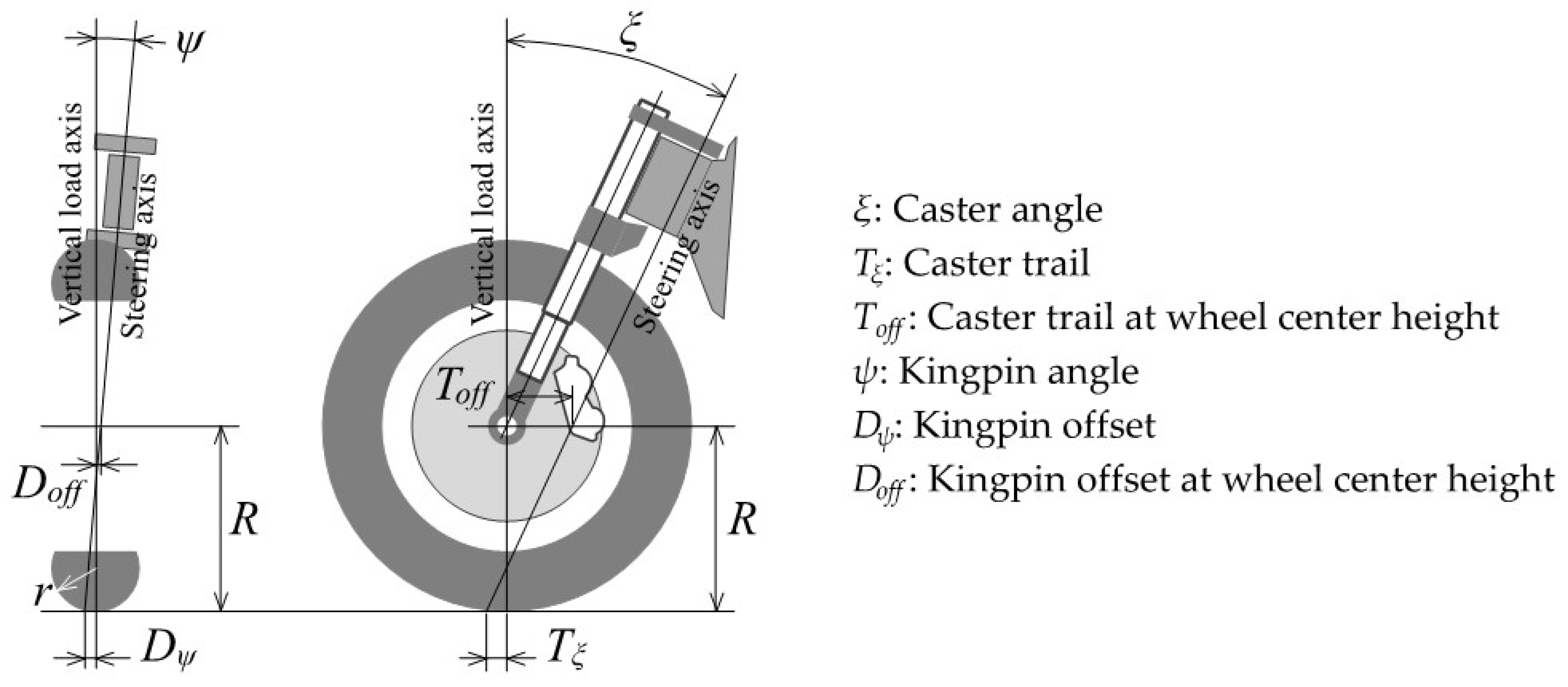
- Front wheel steering axis (caster angle (ξ), caster trail (Tξ), kingpin angle (ψ), kingpin offset (Dψ))
2.2. Configuration of This Report
- Introduction
- Vehicle Characteristics, Design Parameters and Configuration of this Report
- 2.1.
- Vehicle Characteristics and Design Parameters
- 2.2.
- Configuration of this Report
- Materials and Methods
- 3.1.
- Vehicle and Tire Specifications Used in this Report
- 3.1.1.
- Vehicle Specifications
- 3.1.2.
- Tire Specification
- 3.1.3.
- Consideration of Generally Given Tire Camber Characteristic
- 3.2.
- Steering Axis Design Parameters to Derive
- 3.2.1.
- Steering Axis Design Parameters to Derive (Four Unknowns)
- 3.2.2.
- Reduce the number of parameters to Derive (to Two Unknowns) by Previous Studies Related to Steering Axis Geometry
- 1.
- Requirements for Caster Trail Considering Tire Lateral Force on the Road Surface [16]
- 2.
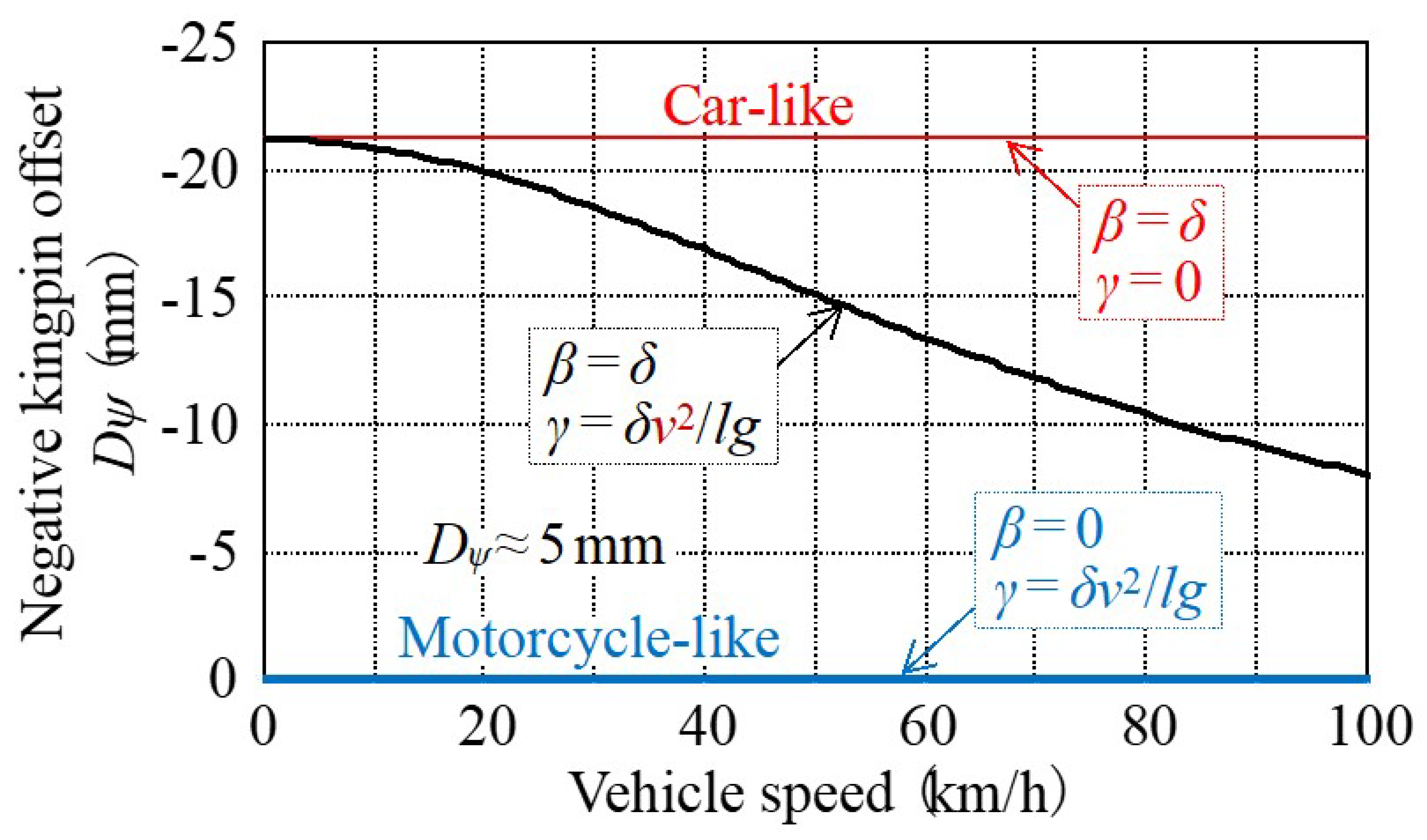
- Kingpin Offset Requirements Considering the Longitudinal Braking Force in the Contact Surface on Straight Running
- Results
- 4.1.
- Derivation of Two Steering Axis Design Parameters from Two Requirements on Steady Characteristics
- 4.1.1.
- A Method to Minimize Steering Disturbance Caused by Uneven Road Surface for Personal Mobility Vehicle (PMV) with Inward-tilting Mechanism
- 1.
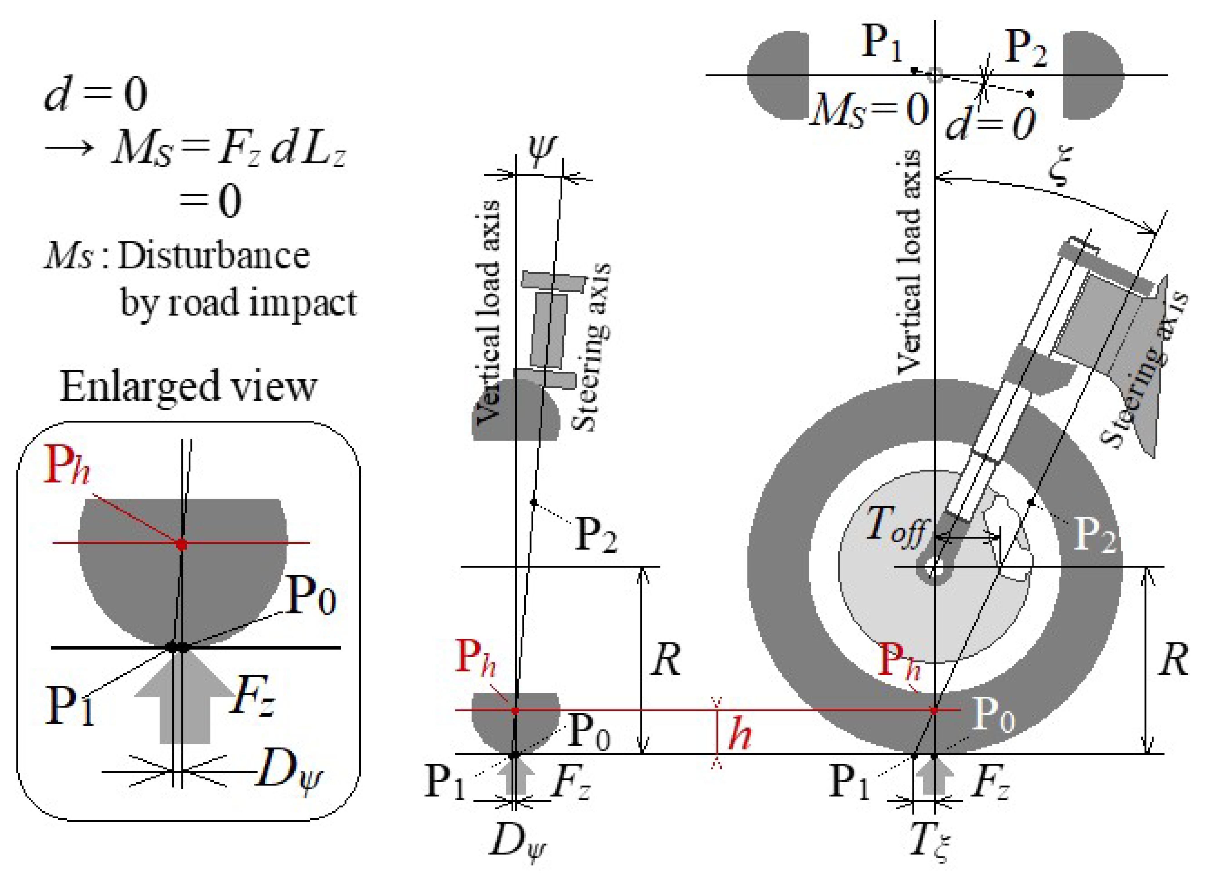
- Minimization of Steering Disturbance due to Reaction Force against the Vertical Load when Standing Upright
- 2.
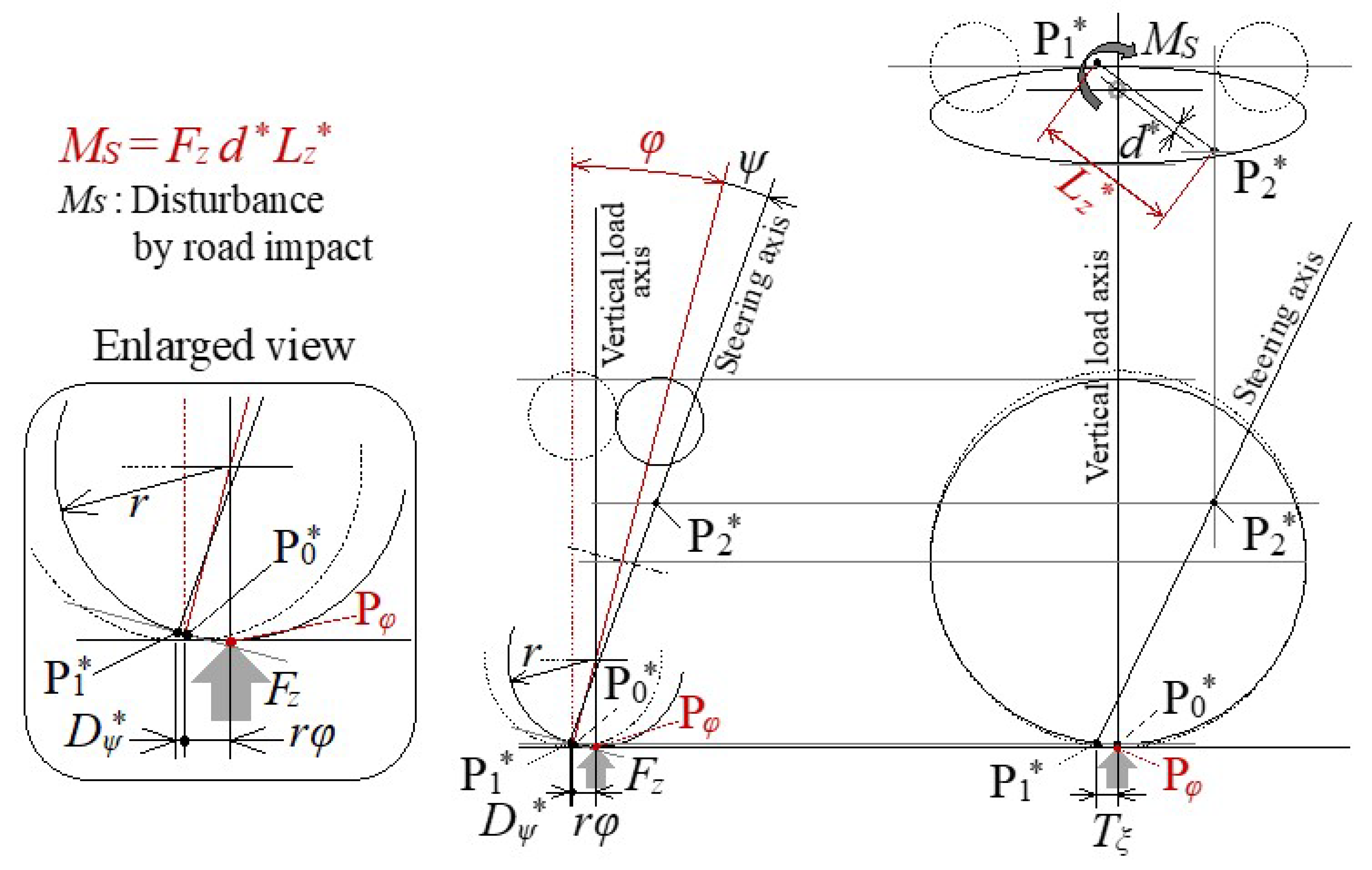
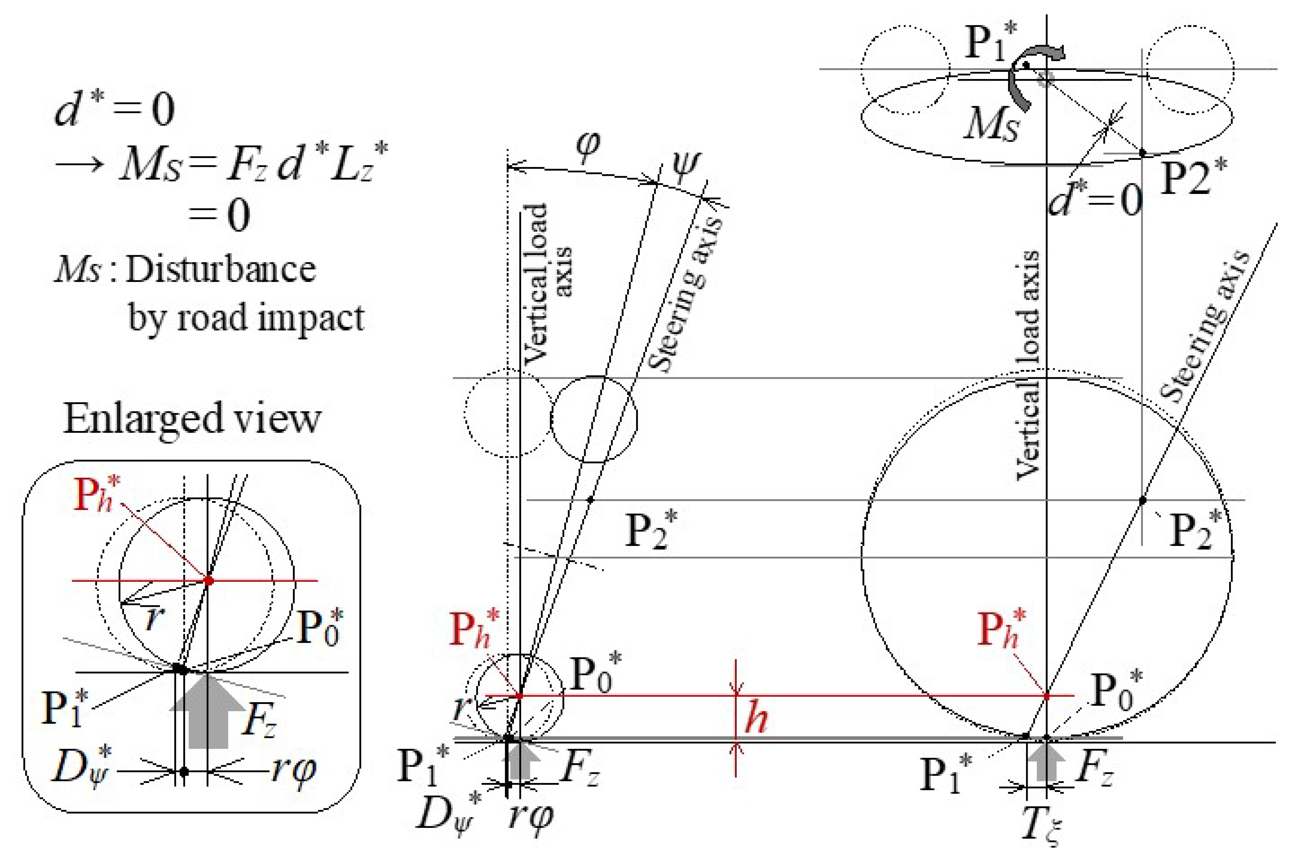
- Maintaining Zero Steering Disturbance due to Reaction Force against the Vertical Load even if the Tire Contact Point Moves Laterally when the Vehicle is Tilted Inward
- 4.1.2.
- Specification Setting Procedure for Minimizing Steering Disturbance due to the Reaction Force against the Vertical Load
- 4.2.
- Vehicle Stability during Disturbance Caused by Uneven Road Surface in the Market, Using the Method to Minimize Steering Disturbance
- 4.2.1.
- Lateral Force Balance on Slanted Road
- 4.2.2.
- Straight Running Stability on Slanted Road
- 4.2.3.
- Straight Running Stability on Rutted Road
- Discussion (Insight into Dynamic Phenomenon Analysis for the Future)
- Conclusions
3. Materials and Methods
3.1. Vehicle and Tire Specifications Used in This Report
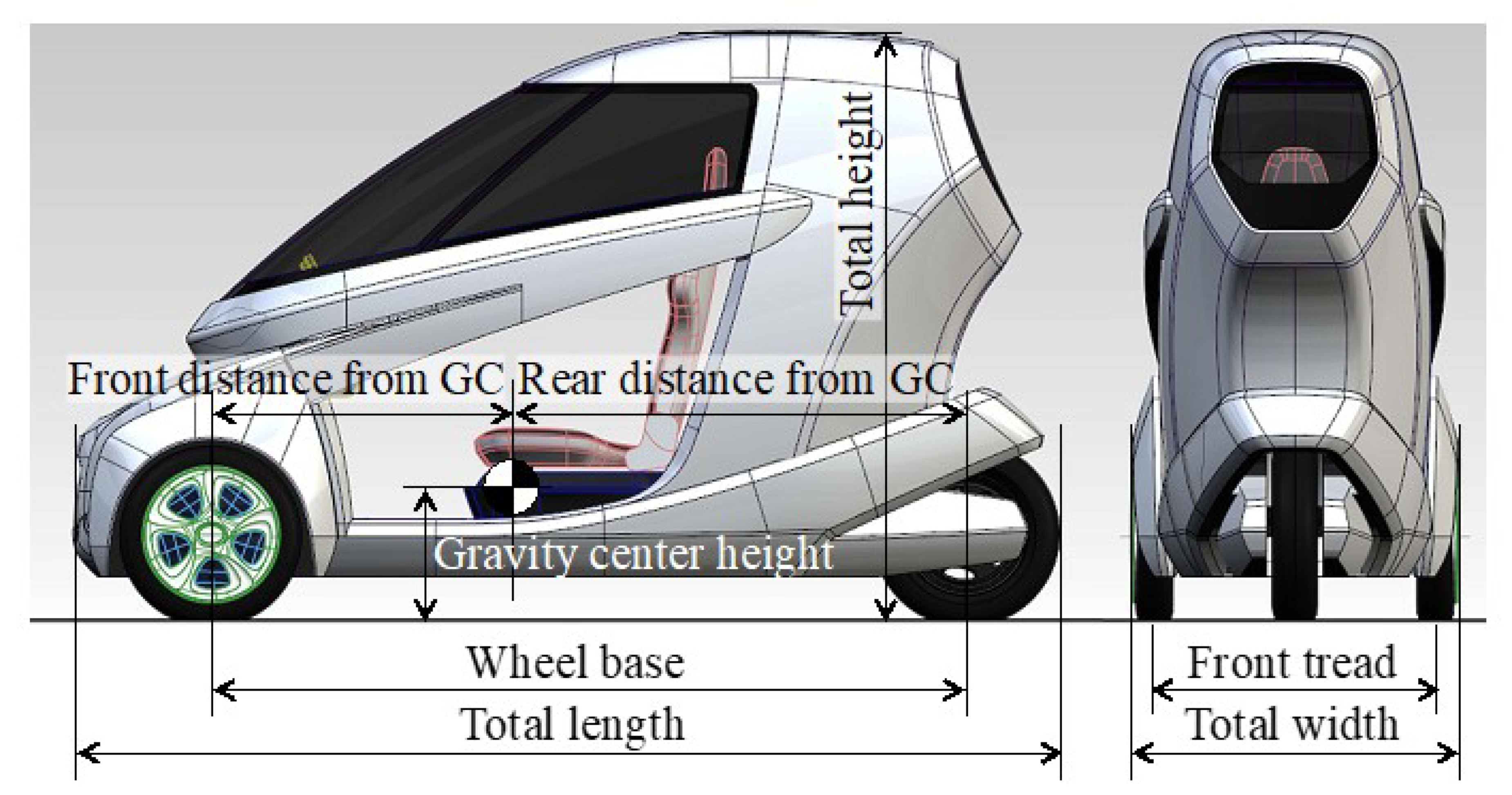
3.1.1. Vehicle Specifications
- TRA: target roll angle
- A: user amplification factor
- δ: tire-steered angle
- v: vehicle speed
- l: wheel base
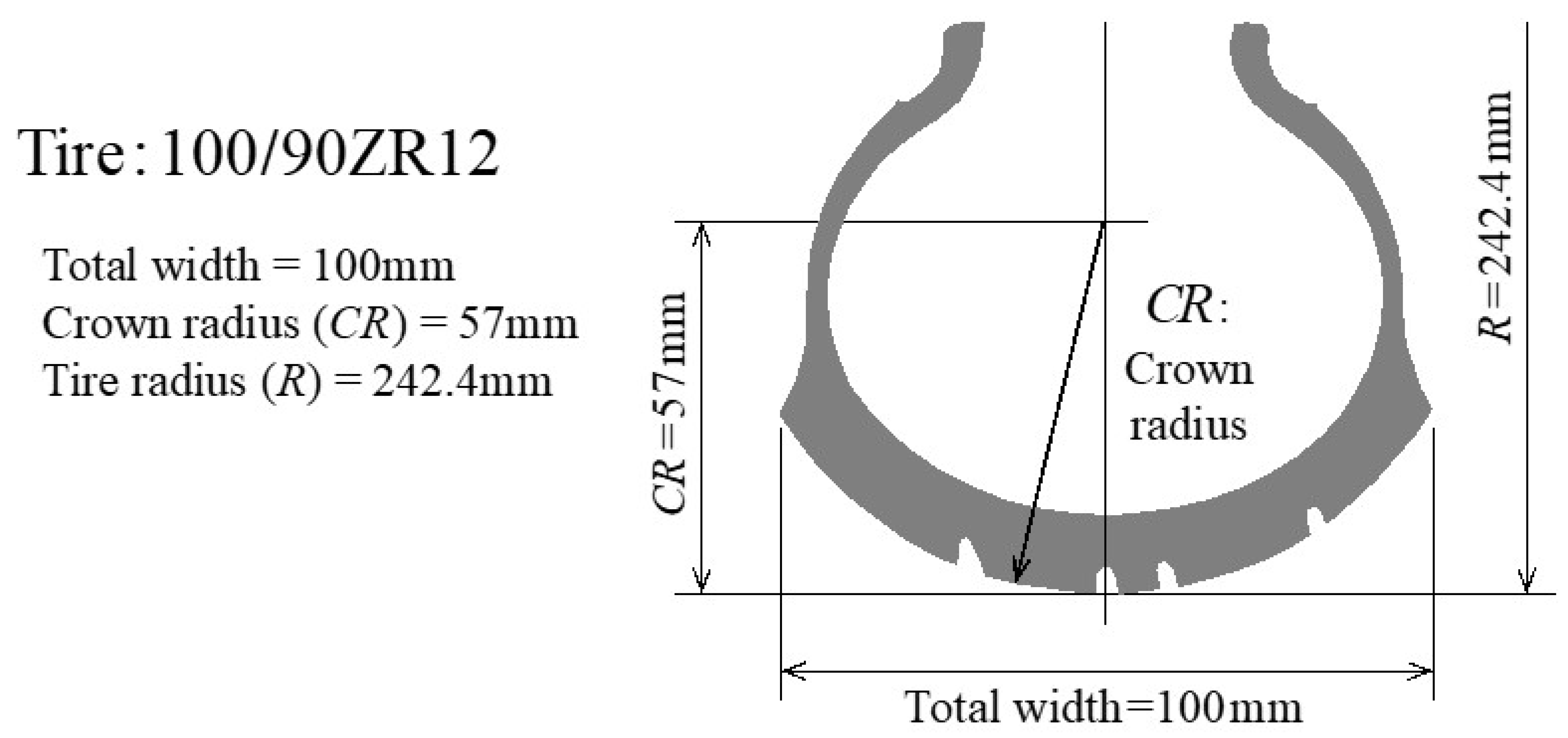
3.1.2. Tire Specifications
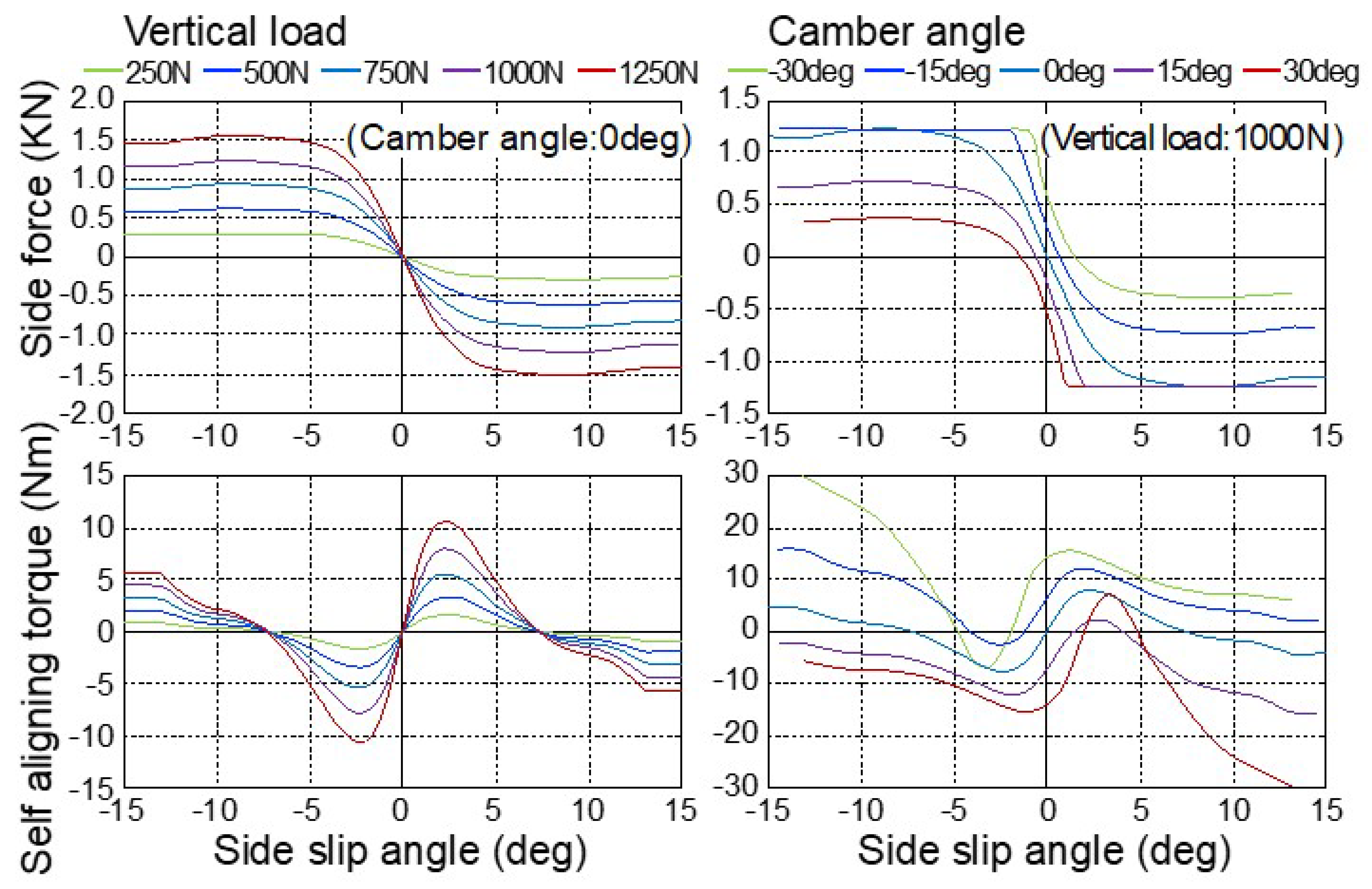
3.1.3. Consideration of Generally Given Tire Camber Characteristics
3.2. Steering Axis Design Parameters to Derive
3.2.1. Steering Axis Design Parameters to Derive (Four Unknowns)
3.2.2. Reduce the Number of Parameters to Derive (to Two Unknowns) by Previous Studies Related to Steering Axis Geometry
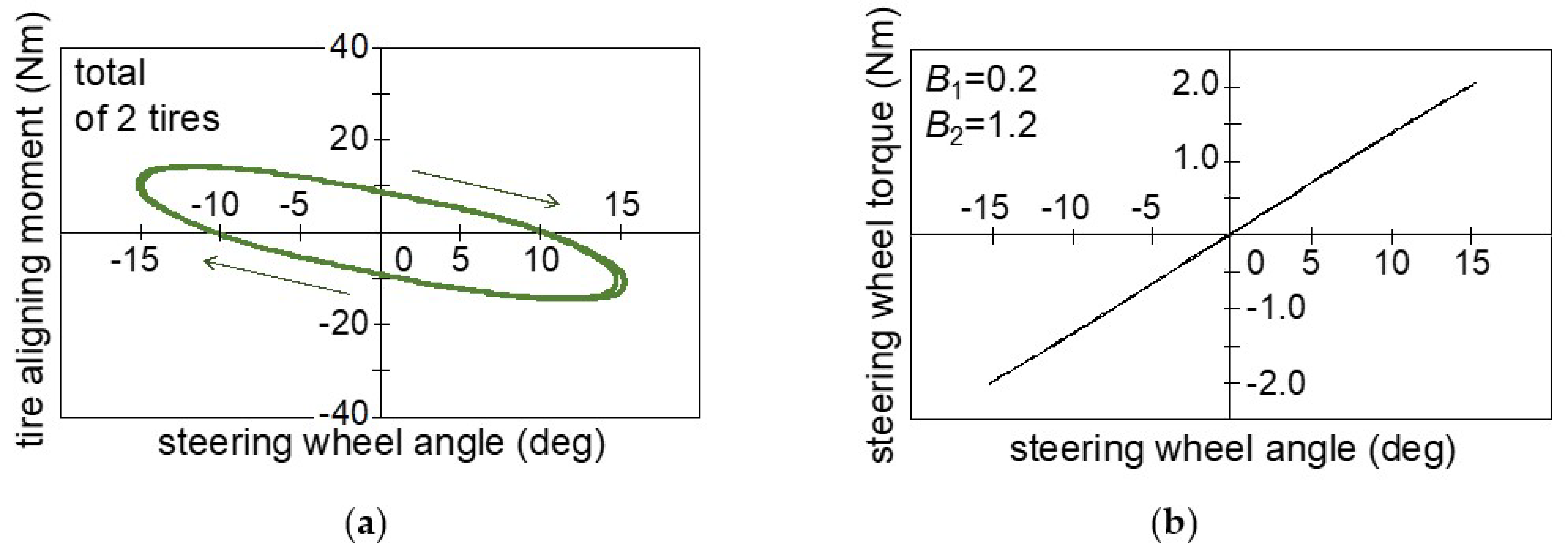
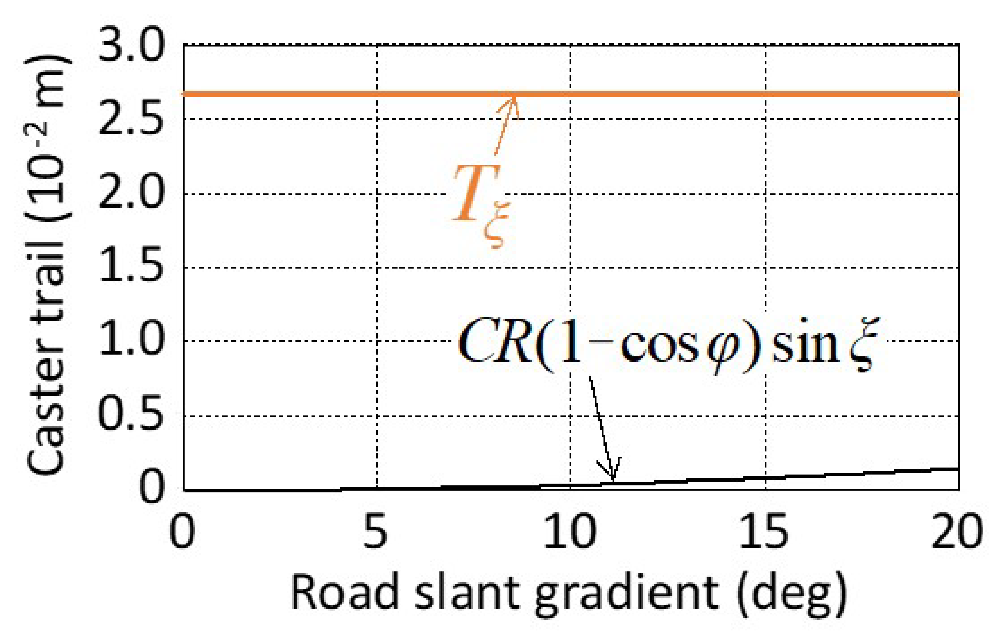
- Requirements for Caster Trail Considering Tire Lateral Force on the Road Surface [16]
- MT: steering wheel torque
- Mz: tire aligning moment
- B1: aligning torque adjustment factor
- Fy: lateral force
- PLA: provisional lateral acceleration
- eγ: tire pneumatic trail on camber angle
- B2: hysteresis adjustment factor
- rs: steering ratio
- φ: tilt angle
- 2.
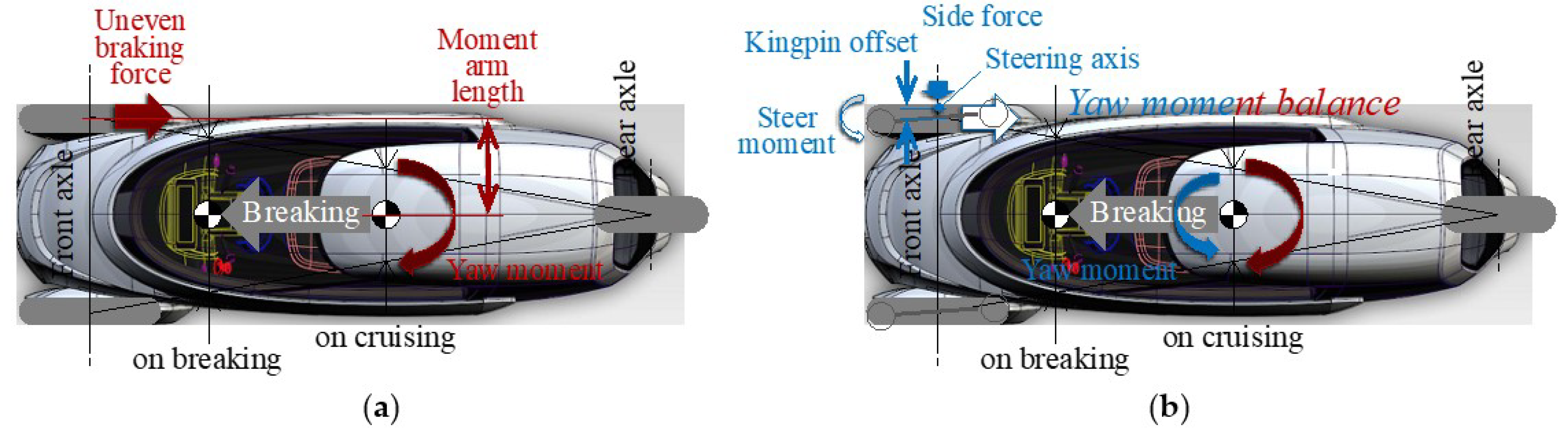
- Kingpin Offset Requirements Considering the Longitudinal Braking Force in the Contact Surface on Straight Running
4. Results
4.1. Derivation of Two Steering Axis Design Parameters from Two Requirements on Steady Characteristics
4.1.1. A Method to Minimize Steering Disturbance Caused by Uneven Road Surface for Personal Mobility Vehicles (PMVs) with Inward-Tilting Mechanism
- Minimization of Steering Disturbance due to Reaction Force against the Vertical Load when Standing Upright
- 2.
- Maintaining Zero Steering Disturbance Due to Reaction Force against the Vertical Load Even If the Tire Contact Point Moves Laterally When the Vehicle Is Tilted Inward
4.1.2. Specification Setting Procedure for Minimizing Steering Disturbance Due to the Reaction Force against the Vertical Load
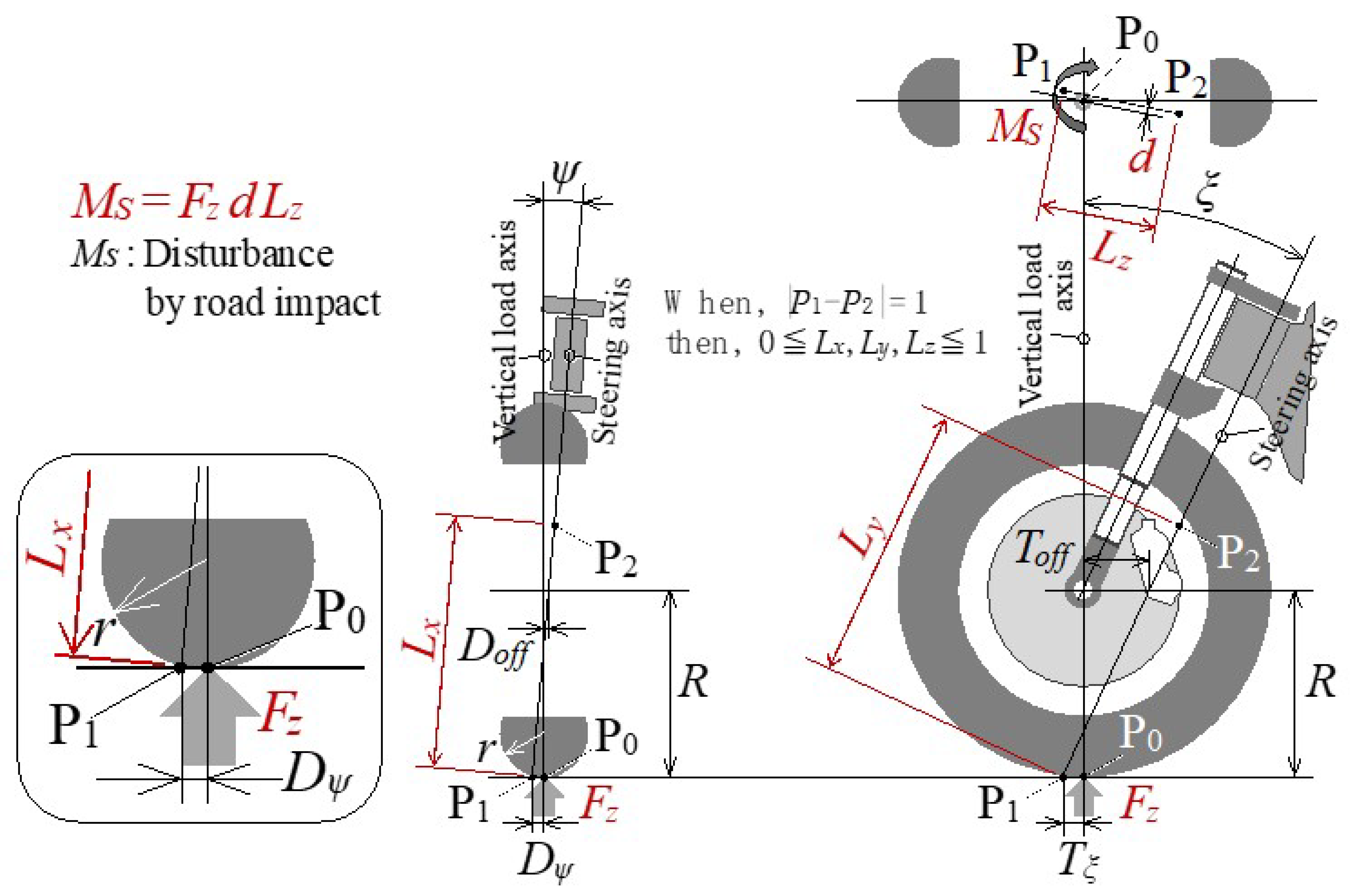
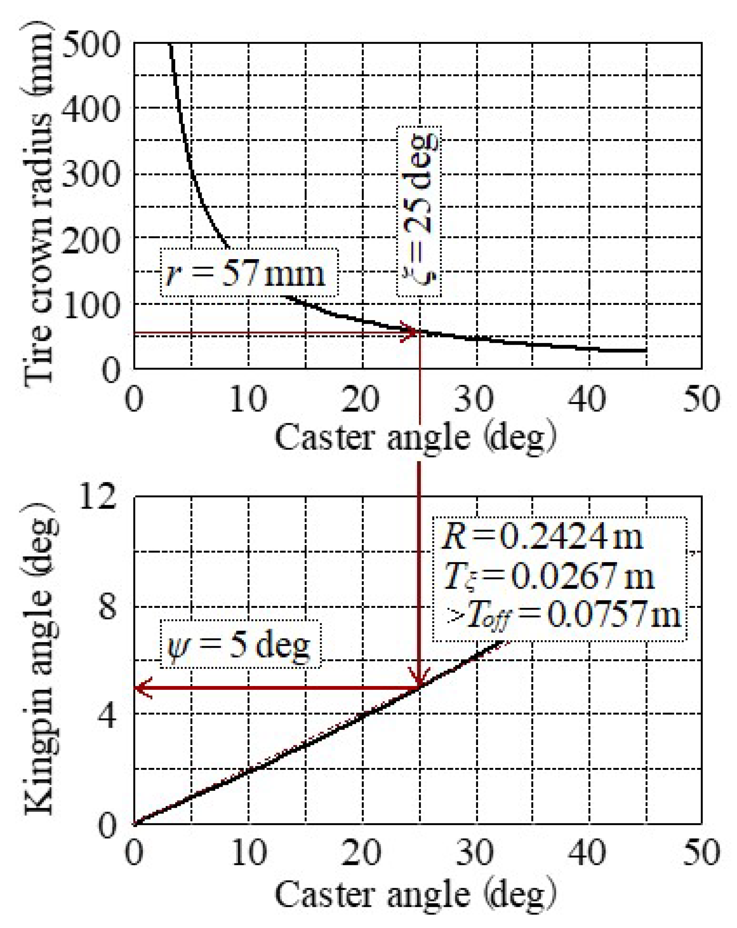
- (1)
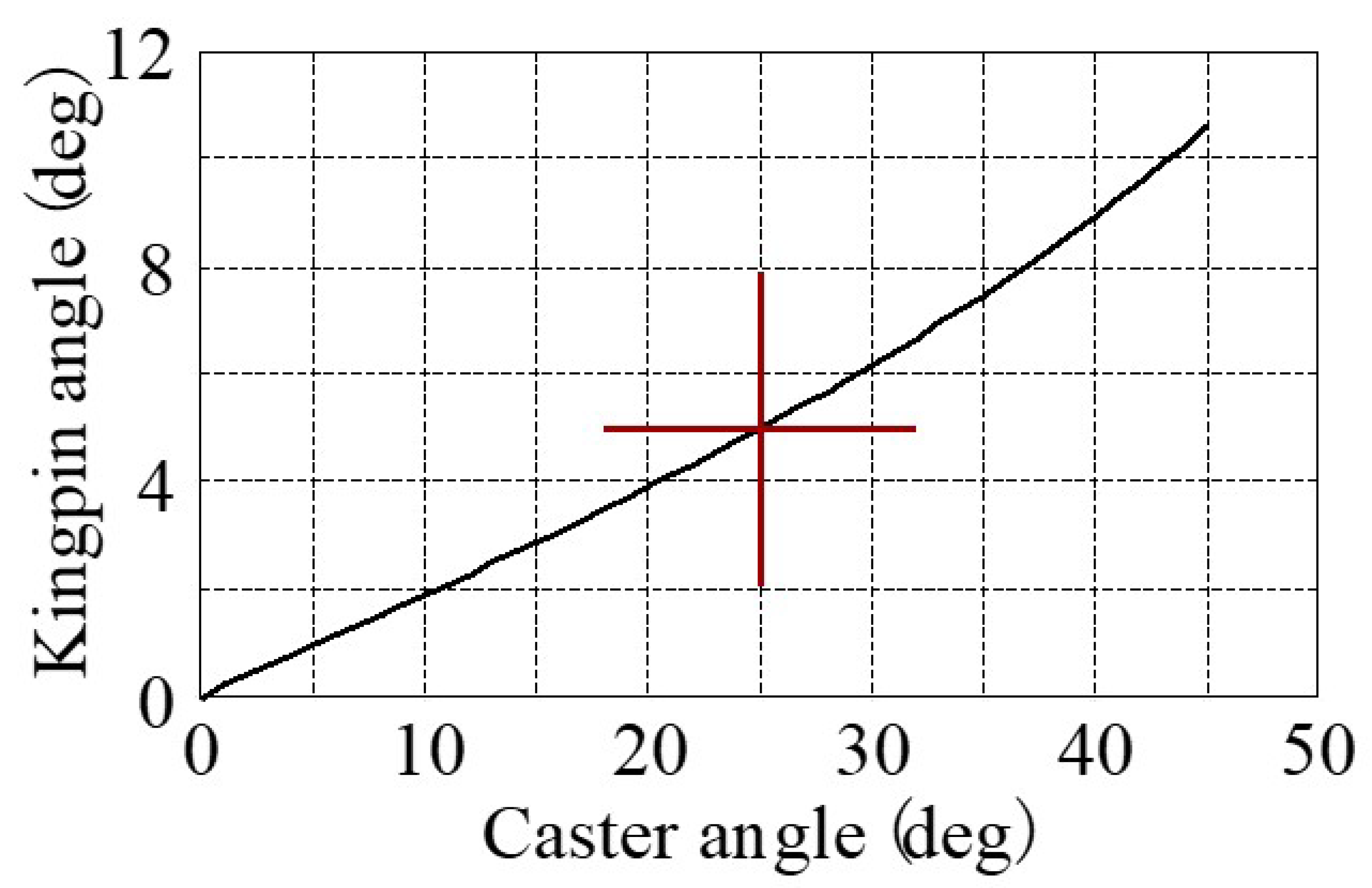
- Caster angle (ξ) = 25 deg is obtained from r = 0.057 m in order to maintain the d value during tilt.
- (2)
- In order to set d = 0 when standing upright, the kingpin angle (ψ) = 5 deg can be obtained from ξ = 25 deg.
4.2. Vehicle Stability during Disturbance Caused by Uneven Road Surface in the Market, Using the Method to Minimize Steering Disturbance
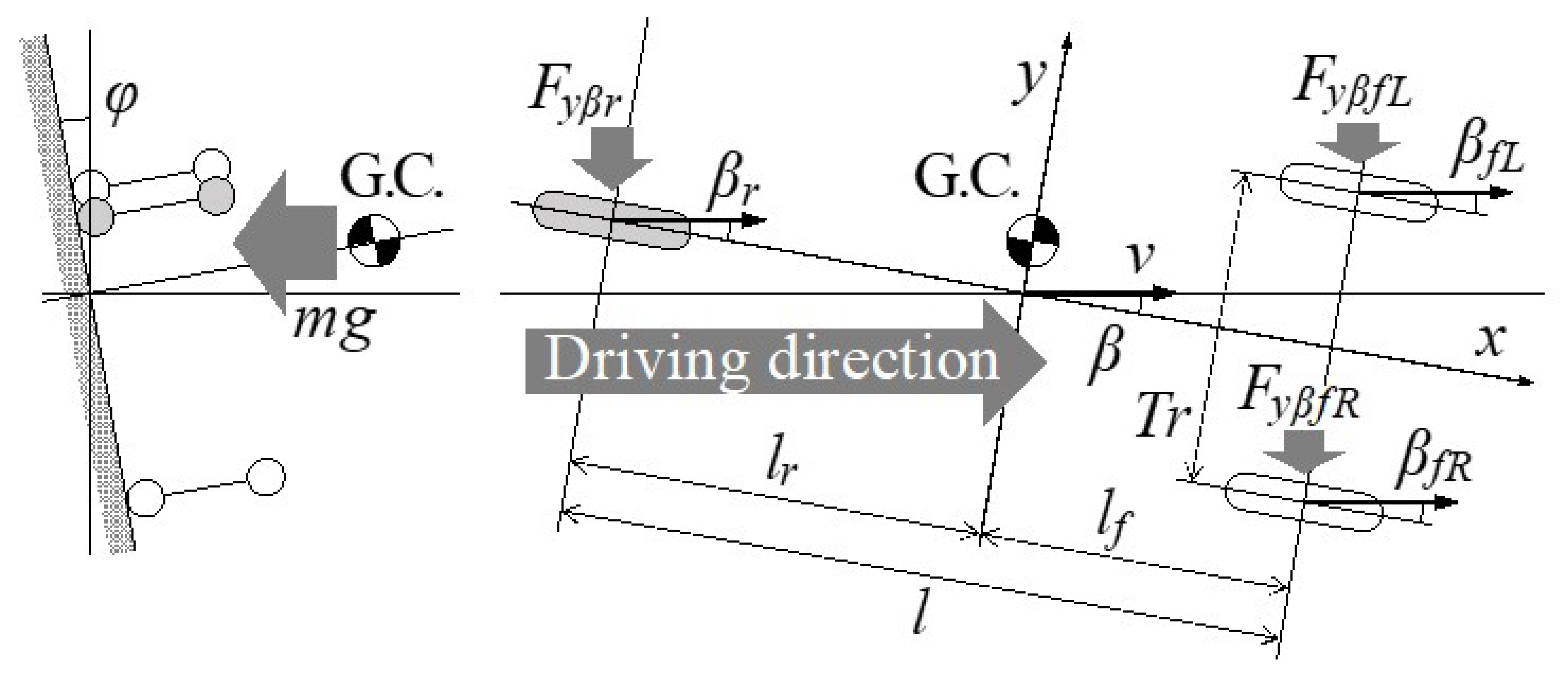
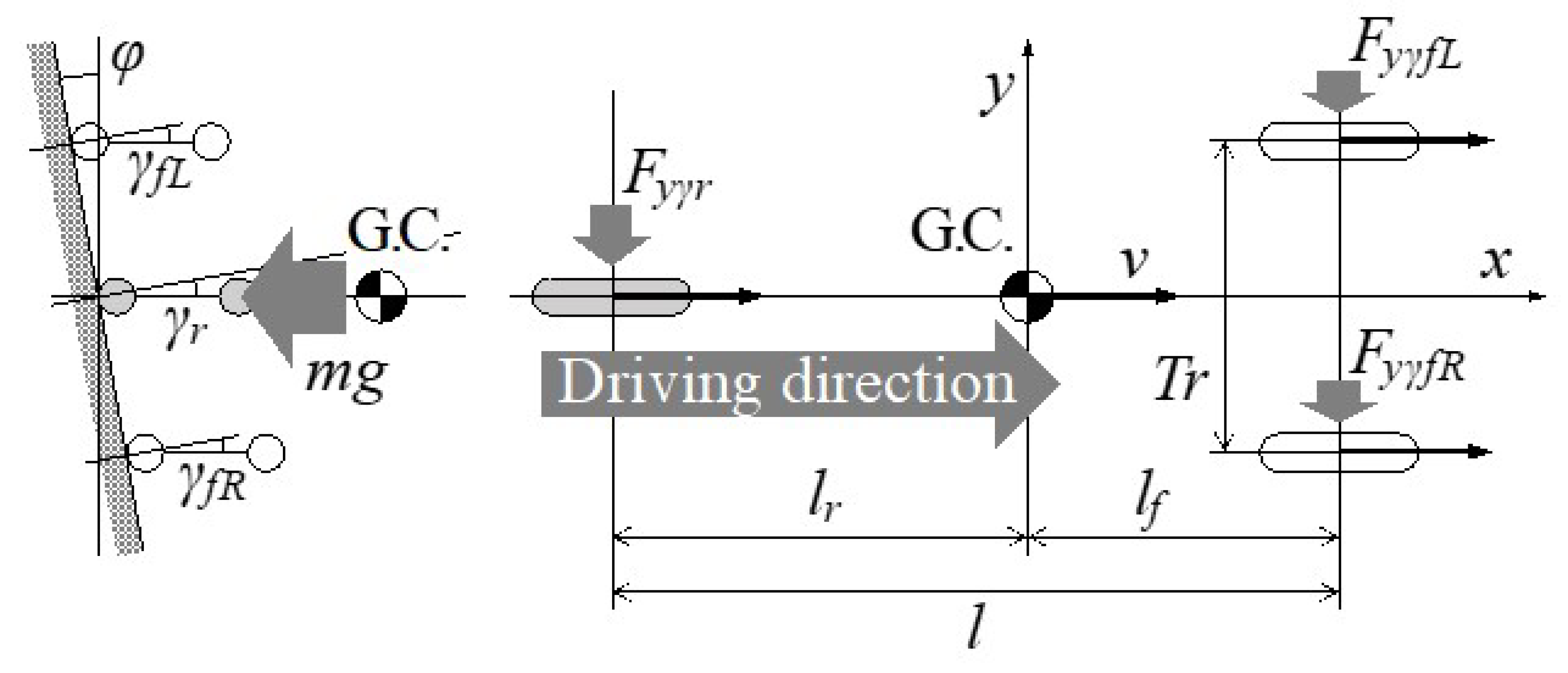
4.2.1. Lateral Force Balance on Slanted Road
- x: longitudinal direction
- y: lateral direction
- v: vehicle speed
- m: vehicle mass
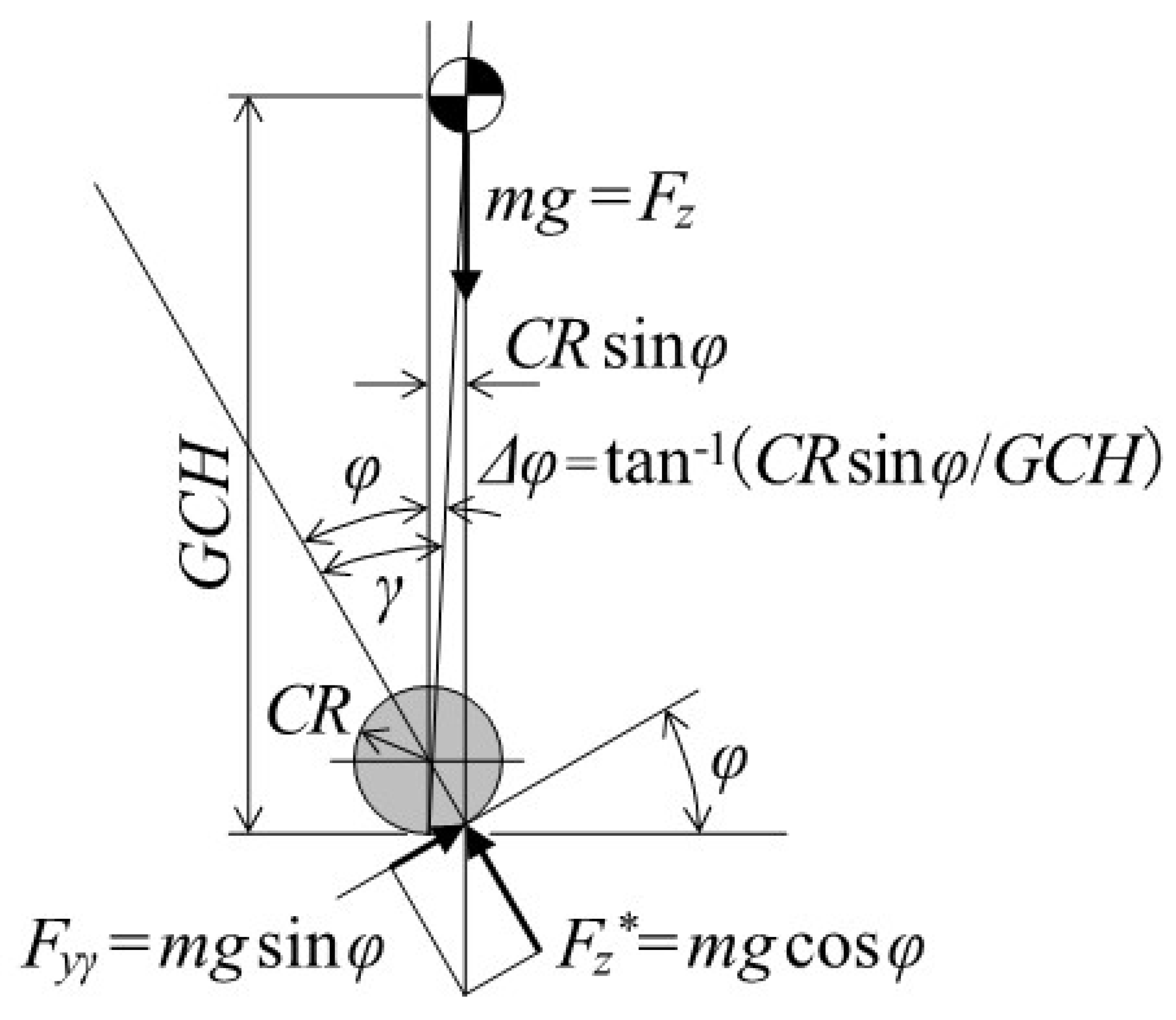
- g: gravitational acceleration
- l: wheel base
- Tr: front tread
- G.C.: gravity center
- lf: front distance from G.C.
- lr: rear distance from G.C.
- φ: slant angle (≈tilt angle)
- GCH: gravity center height
- Ky: cornering stiffness
- Cy: normalized cornering stiffness
- Qy: camber stiffness
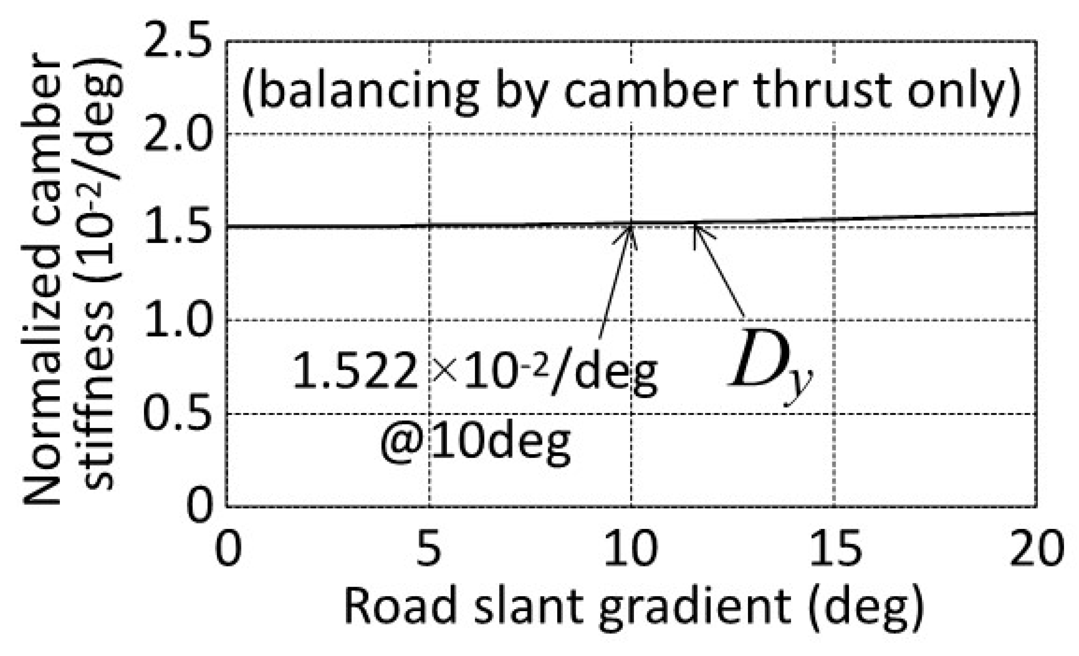
- Dy: normalized camber stiffness
4.2.2. Straight Running Stability on Slanted Road
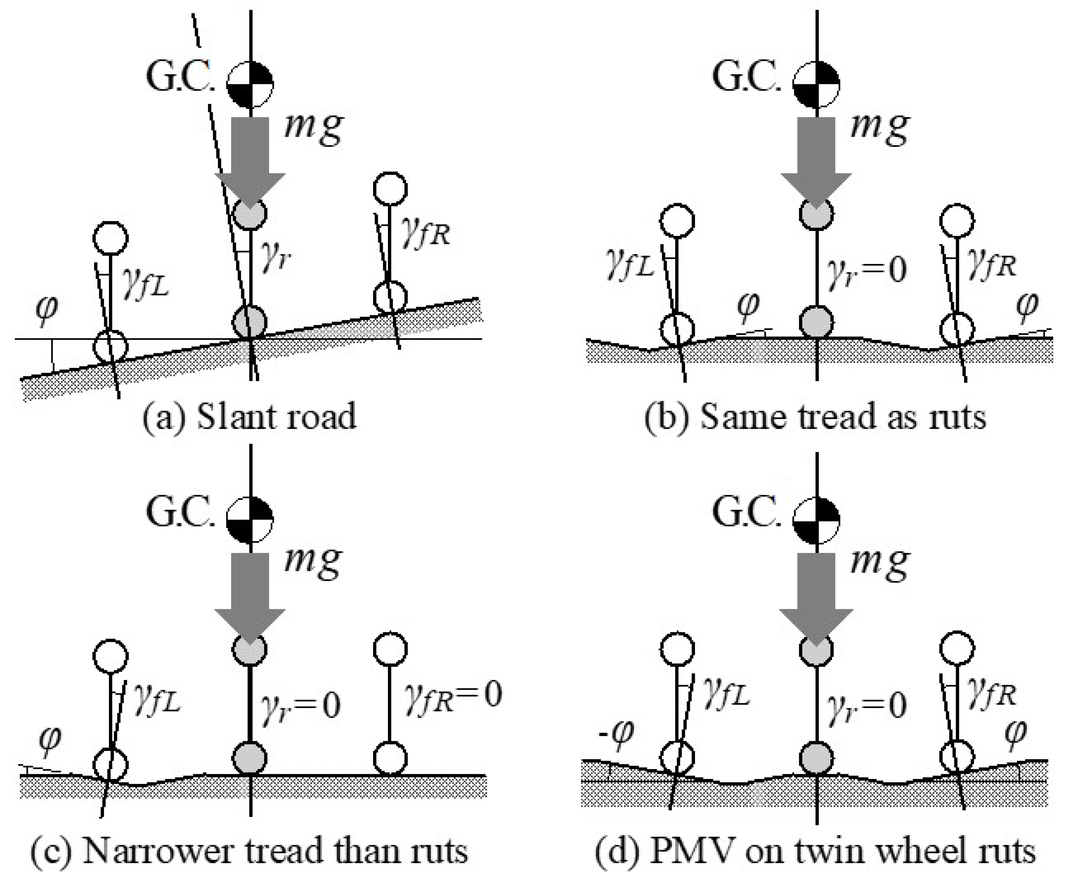
4.2.3. Straight Running Stability on Rutted Road
5. Discussion (Insight into Dynamic Phenomenon Analysis for the Future)
- -
- The dynamic behavior (1 to 2 Hz) of the entire vehicle is considered to be an accumulation of static balances, so in principle it is not affected by disturbances. Therefore, verification in this frequency domain should be entrusted to the confirmation phase with real vehicles.
- -
- The possibility of vehicle response that cannot be explained by static balance due to transient characteristics of tire force and moment (affected by running speed, but about 5Hz at 36km/h, for example), which are not included in the assumptions of this report. Considering the response frequency of the vehicle, the transient vehicle response becomes a point of interest. Therefore, analysis with a dynamic model of the vehicle that incorporates a dynamic tire model is required. The authors are preparing this type of analysis as the next step of the research.
- -
- Unsprung vibrations (approximately 10 Hz or higher), which are not considered in this report, may be transmitted to the entire vehicle in a vibratory manner. In order to reproduce even unsprung vibration, a dynamic model that considers the mass, inertia, and rigidity of each part of the vehicle, including the unsprung mass, is required. Furthermore, at practical speeds (e.g., 72 km/h), the transient characteristics of tires overlap with the frequency range, so analysis using a fairly advanced multi-degree-of-freedom model is required. Analysis of the steering axis arrangement from this point of view is difficult in the short term, and at the same time, it seems to deviate from the research scope of straight running performance of the vehicle on slanted roads and rutted roads.
6. Conclusions
- -
- Based on the characteristics of general motorcycle tires, the centripetal force required for turning is obtained mainly by the camber angle of the tires to the ground (camber thrust). This means the lateral force of each tire is balanced on every angle of transverse slant as mentioned in Section 3.1.3. Therefore, steering torque is focused in order to avoid the disturbances on uneven road surface.
- -
- Four unknown steering axis design parameters (caster angle (ξ), caster trail (Tξ), kingpin angle (ψ), kingpin offset (Dψ)) to derive in order to minimize the steering torque disturbances, are reduced into two unknowns (caster angle (ξ), kingpin angle (ψ)) by previous studies of requirements for caster trail (Tξ) considering tire lateral force and kingpin offset (Dψ), requirements considering the longitudinal braking force as mentioned in Section 3.2.2.
- -
- Two unknown steering axis design parameters (caster angle (ξ), kingpin angle (ψ)) are derived from two vehicle requirements on steady characteristics, as minimization of steering disturbance due to reaction force against the vertical load when standing upright and maintaining zero steering disturbance even if the tire contact point moves laterally when the vehicle is tilted inward, as mentioned in Section 4.1. This derivation is a new knowledge from a completely unique point of view.
- -
- The lateral force balance and minimized steering torque free from the disturbance of each wheel on transverse slant of road surface as mentioned in Section 4.2.1 and Section 4.2.2. Then the free from the disturbance of each wheel on transverse slant gives free from every kind of rut of road surface that is the combination of various transverse slant angles as mentioned in Section 4.2.3.
Author Contributions
Funding
Data Availability Statement
Conflicts of Interest
References
- Haraguchi, T. 4. Personal Mobility Vehicle. In Mobility Service, Mobility Innovation Series; Corona Publishing Co., Ltd.: Tokyo, Japan, 2020; Volume 1, pp. 92–123. ISBN 978-4-339-02771-6. [Google Scholar]
- Haraguchi, T. Prospects for Future Personal Mobility (PMV) from a Historical Background. In Automotive Technology; Technical Information Institute Co., Ltd.: Tokyo, Japan, 2020; Volume 8, pp. 63–67. ISSN 2432-5694. [Google Scholar]
- Kaneko, T.; Kageyama, I.; Haraguchi, T.; Kuriyagawa, Y. A Study on the Harmonization of a Personal Mobility Vehicle with a Lean Mechanism in Road Traffic (1st Report): Micro-Scale Traffic Flow Simulation in Consideration of Mutual Interference of Driver Risk Feeling. In Proceedings of the JSAE Annual Meeting, Yokohama, Japan, 25–27 May 2016; pp. 1350–1354. [Google Scholar]
- Haraguchi, T.; Kaneko, T.; Kageyama, I.; Kuriyagawa, Y.; Kobayashi, M. Study of Tilting Type Personal Mobility Vehicle by the Immersive Driving Simulator with Five Large Screens. Trans. JSAE 2017, 48, 693–698. [Google Scholar]
- Haraguchi, T.; Kaneko, T.; Kageyama, I. Market Acceptability Study on Energy Balance of Personal Mobility Vehicle (PMV) with Active Tilting Mechanism. In Proceedings of the JSAE Annual Meeting, Yokohama, Japan, 22–24 May 2019; pp. 1–6. [Google Scholar]
- Haraguchi, T.; Kageyama, I.; Kaneko, T. Study of Personal Mobility Vehicle (PMV) with Active Inward Tilting Mechanism on Obstacle Avoidance and Energy Efficiency. Appl. Sci. 2019, 9, 4737. [Google Scholar] [CrossRef]
- Haraguchi, T.; Kaneko, T.; Kageyama, I.; Kobayashi, M.; Murayama, T. Obstacle Avoidance Maneuver of Personal Mobility Vehicles with Lean Mechanism: Comparison between Front and Rear Wheel Steering. In Proceedings of the JSAE Annual Meeting, Yokohama, Japan, 24–26 May 2017; pp. 494–499. [Google Scholar]
- Kaneko, T.; Kageyama, I.; Haraguchi, T. Dynamic Rollover Characteristics of Personal Mobility Vehicles with Lean Mechanism. In Proceedings of the JSAE Annual Meeting, Osaka, Japan, 11 October 2017; pp. 1392–1397. [Google Scholar]
- Haraguchi, T.; Kaneko, T.; Kageyama, I. Study on Steering Response of Personal Mobility Vehicle (PMV) by Comparison of PMV with Passenger Cars and Motorcycles on the Obstacle Avoidance Performance. In Proceedings of the JSAE Annual Meeting, Nagoya, Japan, 17–19 October 2018; pp. 1–6. [Google Scholar]
- Haraguchi, T.; Kageyama, I.; Kaneko, T. Inner Wheel Lifting Characteristics of Tilting Type Personal Mobility Vehicle by Sudden Steering Input. Trans. JSAE 2019, 50, 96–101. [Google Scholar]
- Kaneko, T.; Kageyama, I.; Haraguchi, T. A Study on Characteristics of the Vehicle Response by Abrupt Operation and an Improvement Method for Personal Mobility Vehicle with Leaning Mechanism. Trans. JSAE 2019, 50, 796–801. [Google Scholar]
- Haraguchi, T.; Kaneko, T.; Kageyama, I. Steering Torque Characteristics of Personal Mobility Vehicle (PMV) with Inward Tilting Mechanism. Trans. JSAE 2020, 51, 931–937. [Google Scholar]
- Haraguchi, T.; Kaneko, T.; Kageyama, I. Steering Torque Hysteresis of Personal Mobility Vehicle (PMV) with Inward Tilting Mechanism. Trans. JSAE 2021, 52, 987–993. [Google Scholar]
- Haraguchi, T.; Kaneko, T.; Kageyama, I. A Study of Steer Characteristics of Personal Mobility Vehicle (PMV) with Inward Tilting Mechanism. Trans. JSAE 2022, 53, 58–64. [Google Scholar]
- Aldegheishem, A.; Alrajeh, N.; Parra, L.; Romero, O.; Lloret, J. Driving Assistance System for Ambulances to Minimise the Vibrations in Patient Cabin. Electronics 2022, 11, 3965. [Google Scholar] [CrossRef]
- Haraguchi, T.; Kaneko, T.; Kageyama, I. A Method to Minimize Steering Disturbance Caused by Vertical Load Reaction Force of Personal Mobility Vehicle (PMV) with Inward Tilting Mechanism. Trans. JSAE 2021, 52, 462–468. [Google Scholar]
- Kato, K.; Haraguchi, T. Improvement on Steering Pull during Braking on Wheel Tracks. J. Soc. Automot. Eng. Jpn. 1994, 48, 66–71. [Google Scholar]
- Kato, K.; Haraguchi, T. Improvement on steering pull during braking on rutted road. JSAE Rev. 1996, 17, 71–74. [Google Scholar] [CrossRef]
- Yamada, Y.; Haraguchi, T. Analysis of Vehicle Drift on the Cant Road. J. Soc. Automot. Eng. Jpn. 1995, 49, 65–70. [Google Scholar]
- Kageyama, I.; Makita, M.; Kuriyagawa, Y. Fundamental Study on Directional Control of PMV Using Large Camber Angle Control. Trans. JSAE 2015, 46, 919–924. [Google Scholar]
- Kageyama, I.; Kuriyagawa, Y.; Haraguchi, T.; Kobayashi, Y. Two-wheeled Vehicle Characteristics on Steady State Turning Considering Equivalent Compliance. Trans. JSAE 2019, 50, 1402–1408. [Google Scholar]


| Item | Unit | Value | Item | Unit | Value |
|---|---|---|---|---|---|
| Total length | m | 2.645 | Total mass | kg | 369.8 |
| Total width | m | 0.880 | Front mass distribution | kg | 222.1 |
| Total height | m | 1.445 | Rear mass distribution | kg | 147.7 |
| Wheel base | m | 2.020 | Roll moment of inertia | kgm2 | 58.8 |
| Front distance from gravity center | m | 0.807 | (Roll moment of inertia of sprung mass) | kgm2 | 43.0 |
| Rear distance from gravity center | m | 1.213 | Pitch moment of inertia | kgm2 | 197.3 |
| Front tread | m | 0.850 | (Pitch moment of inertia of sprung mass) | kgm2 | 118.0 |
| Gravity center height | m | 0.358 | Yaw moment of inertia | kgm2 | 187.3 |
| Steering gear ratio | - | 16.0 | (Yaw moment of inertia of sprung mass) | kgm2 | 102.3 |
| Item | Value | Item | Value |
|---|---|---|---|
| Tire radius: R | 0.242 m | Crown radius: CR | 0.057 m |
| Cornering stiffness: Ky | 427.4 N/deg | Camber stiffness: Qy | 17.77 N/deg |
| Normalized Ky: Cy | 42.74 × 10⁻²/deg | Normalized Qy: Dy | 1.777 × 10⁻²/deg |
| Pneumatic trail on slip angle: eβ | 0.0136 m | Pneumatic trail on camber angle: eγ | −0.0267 m |
Disclaimer/Publisher’s Note: The statements, opinions and data contained in all publications are solely those of the individual author(s) and contributor(s) and not of MDPI and/or the editor(s). MDPI and/or the editor(s) disclaim responsibility for any injury to people or property resulting from any ideas, methods, instructions or products referred to in the content. |
© 2023 by the authors. Licensee MDPI, Basel, Switzerland. This article is an open access article distributed under the terms and conditions of the Creative Commons Attribution (CC BY) license (https://creativecommons.org/licenses/by/4.0/).
Share and Cite
Haraguchi, T.; Kaneko, T. Design Requirements for Personal Mobility Vehicle (PMV) with Inward Tilt Mechanism to Minimize Steering Disturbances Caused by Uneven Road Surface. Inventions 2023, 8, 37. https://doi.org/10.3390/inventions8010037
Haraguchi T, Kaneko T. Design Requirements for Personal Mobility Vehicle (PMV) with Inward Tilt Mechanism to Minimize Steering Disturbances Caused by Uneven Road Surface. Inventions. 2023; 8(1):37. https://doi.org/10.3390/inventions8010037
Chicago/Turabian StyleHaraguchi, Tetsunori, and Tetsuya Kaneko. 2023. "Design Requirements for Personal Mobility Vehicle (PMV) with Inward Tilt Mechanism to Minimize Steering Disturbances Caused by Uneven Road Surface" Inventions 8, no. 1: 37. https://doi.org/10.3390/inventions8010037