Article

Finite Element Analysis in the Balancing Phase for an Open Source Transfemoral Prosthesis with Magneto-Rheological Damper

by
Sebastian Muñoz-Vásquez
1,
Zuly Alexandra Mora-Pérez
1,
Paolo Andrés Ospina-Henao
2,
César Hernando Valencia-Niño
1,
Marcelo Becker
3 and
Jorge Guillermo Díaz-Rodríguez
4,*
1
Mechatronics Engineering, Universidad Santo Tomás, Carrera 18 No. 9-27, Bucaramanga 680011, Colombia
2
Basic Sciences Department, Universidad Santo Tomás, Carrera 18 No. 9-27, Bucaramanga 680011, Colombia
3
Mechanical Engineering Department, Universidade de São Paulo, Av. Trab. São Carlense, 400–Arnold Schimidt Park, São Carlos 13566-590, Brazil
4
School of Mechanical Engineering, Universidad Industrial de Santander, Carrera 27 Calle 9, Bucaramanga 680002, Colombia
*
Author to whom correspondence should be addressed.
Inventions 2023, 8(1), 36; https://doi.org/10.3390/inventions8010036
Submission received: 1 December 2022 / Revised: 16 January 2023 / Accepted: 19 January 2023 / Published: 31 January 2023
(This article belongs to the Special Issue Innovations in 3D Printing 2.0)

Abstract

:
The article presents a finite element simulation for the stress analysis of a transfemoral prosthesis with damping for a 100 kg person in the balancing phase. The maximum force is exerted at this stage when the person supports his or her whole body on a single foot. Materials used included stainless steel and polymer matrix composites, for which mechanical testing was performed. The study applied the SolidWorks simulation software tools, where material properties were specified for each part that composes the prosthesis and considered loads, the fastenings, and the meshing. The simulation resembles the manufacturing process for each component, including the sole built by the novel composite fused deposition modeling technique. As a result of the simulation, the stress, displacement fields, and safety factor are obtained. Analysis of the safety factor indicates that the components can withstand the loads imposed. Finally, a fatigue analysis indicated that the most critically loaded component lasts at least 294,107 cycles at maximum constant loading.

1. Introduction

Worldwide, amputation is considered a public health problem due to the fact that approximately 2800 amputations are performed daily. Out of these, about 113,000 lower limb amputations are performed each year. Moreover, due to the long internal Colombian armed conflict from 1990 to 2008 and the extensive use of landmines, the number of amputees has reached 6724 among military and civilian personnel [1]; about 42 million people in Latin America are somehow physically challenged by different reasons [2]. However, that is not the only cause of lost limbs, and accidents (motorcycles, cars, and work-related) [3] and osteoporosis [4] are other significant sources of such losses. The loss of a limb is a traumatic event in one’s life that brings physical, psychological, and social changes [1,2,5,6,7]. A prosthesis may partially restore the patient’s mobility [8] and confidence [1,6].
On the other hand, the ongoing popularization of additive manufacturing (AM) has made it possible to create customized parts such as prosthetics [6,9,10]. However, these materials must be carefully selected and simulated so that unique geometries and inherent anisotropy can withstand service loads [11]. Manufacturing must be considered as well to consider geometric restrictions depending on the AM technology chosen [12,13].
One of the tasks in product design is ensuring that the parts that compose the design can withstand the applied loads [14]. That is why each part of the CAD model of the prosthesis is subjected to a stress analysis where the material is defined with its respective mechanical properties, appropriate mesh, and boundary conditions to know the response of the part under these conditions to validate the design [2,5].
Therefore, different lower limb prosthetic design examples were presented [2,9,15,16,17,18,19], and computational tools were used to model the mechanical response. Mankai et al. [20] presented a housing shell made out of a natural fiber-reinforced composite. Gualdrón et al. [21] proposed a method to map the geometry of the lower limb socket based on image reconstruction. Konya and Verim [4] used FEM analysis to measure the influence of the proximal lag screw on the femur’s mechanical response. Wevers and Durance [22] presented fatigue testing of a high-density polyethylene housing subjected to a rectified sinusoidal 1.4 kN axial load with peaks at 93, 69, and 100% (in that order) of the maximum and a minimum load just below zero for one walking cycle. Jelačić et al. [23] presented a hydraulic-powered prosthesis. Finally, [24,25] presented detailed modeling of human gait.
Today’s computational tools are widely used for conducting analysis and prototype simulations to validate design features [26]. For example, SolidWorks software implements the finite element method (FEM) to approximate the solution of partial differential equations to obtain a result corresponding to reality. This is done by dividing the part into small finite elements interconnected by nodes. The set of nodes is called the mesh that varies from coarse to fine. Before running an FEM analysis, one must set the type of mesh in the software according to the simulation’s desired result based on the part’s application [26].
In this work, a 1.6 m tall and 100 kg amputee critical force in the rolling phase was considered when only one foot is in contact with the ground when the maximum force is exerted [19]. The idea of a generic transfemoral prosthesis design is to offer an off-the-shelf solution, only leaving the need to patient-customize the socket, which adapts the limb to the prosthesis. Such a design should lower the waiting time for a prosthesis, thus accelerating the patient’s recovery. Furthermore, the proposed prosthetic leg includes a magnetorheological (MR) damper [27] to better adapt to the force change and enhance damping, thus transferring less force to the patient. Such control is treated somewhere else [28,29]. Subsequently, each of the parts that make up the prosthesis is described, and the results given by FEM are shown. With that in mind, we performed a life prediction for the prosthesis as added value for the design. Finally, the web version of this article includes the blueprints and *.STL files used in this study for anyone to build or modify a lower limb prosthetic leg.

2. Materials and Methods

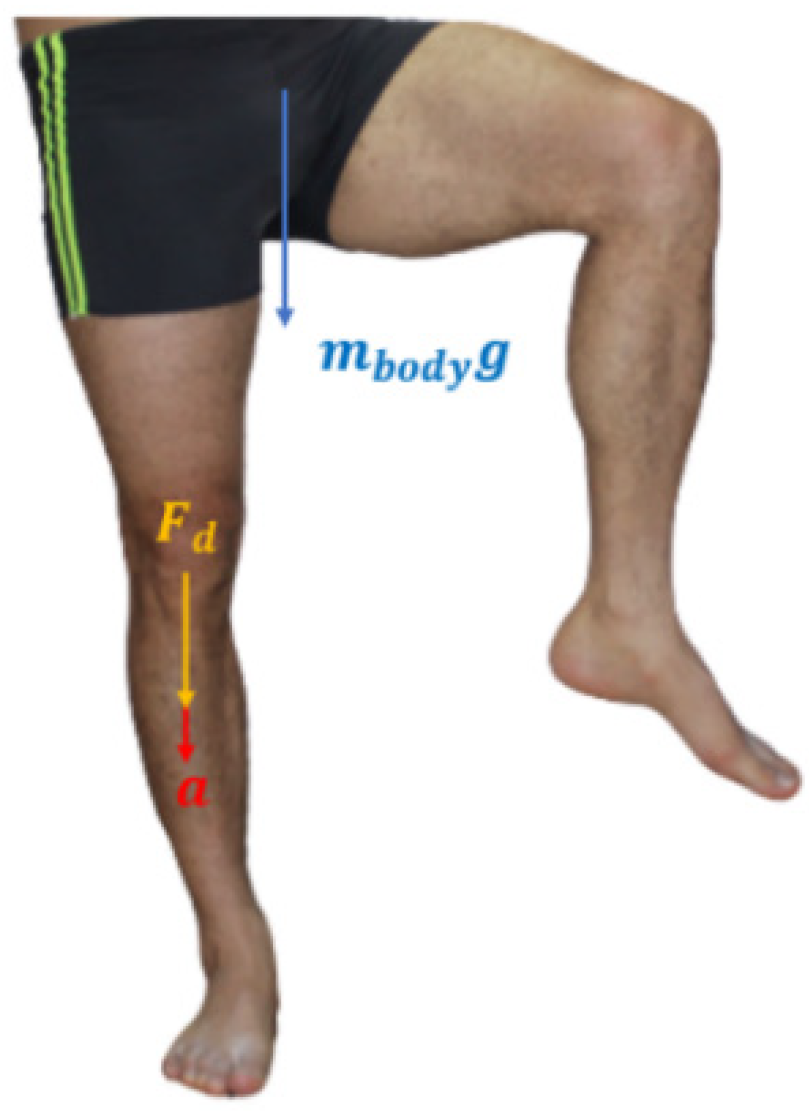
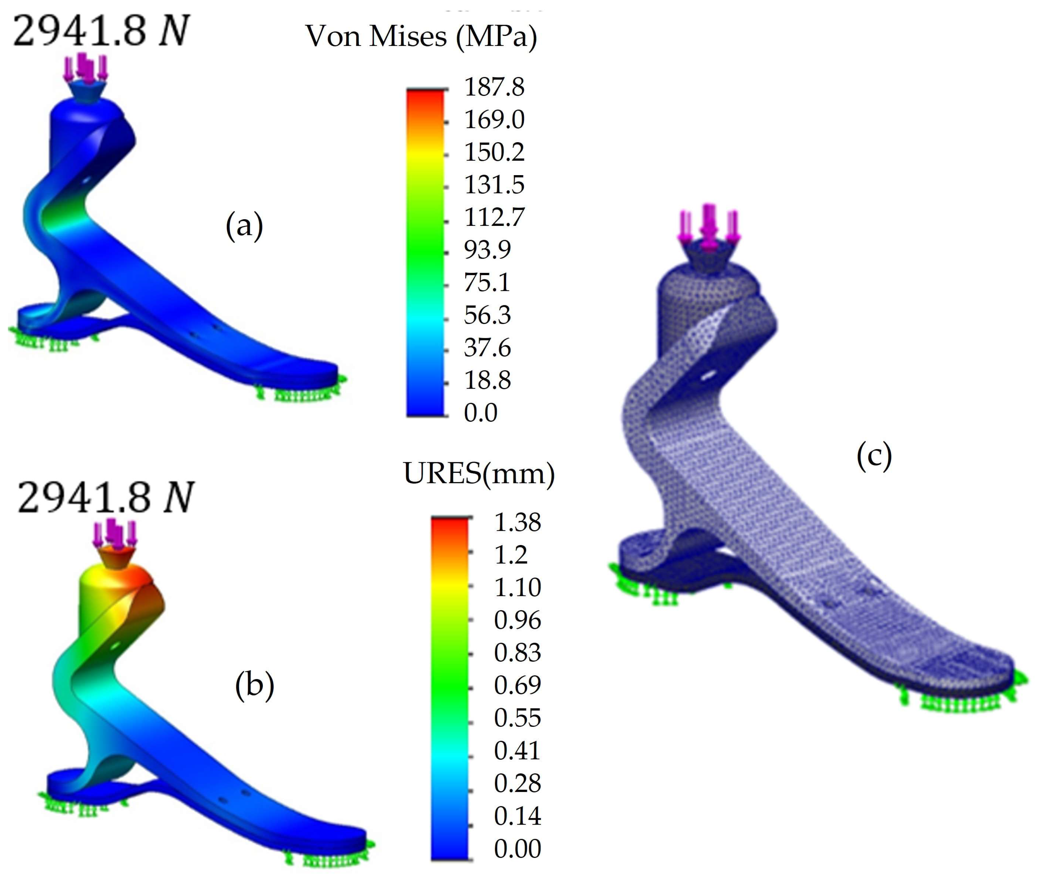
2.1. Balancing Phase Force Analysis

The critical force is considered when the acceleration determined by the speed variation in a specific time changes until reaching a final value due to gravity [30]. For example, when the body comes into contact with the ground from a drop height h of 0.2 m and a displacement of the center of mass dcm of 0.04 m, the final speed according to Erazo and Mera [18] is calculated as shown in Equation (1).
v f = 2 g h
where v f and v i are the final and initial speeds, respectively. The time when the body falls due to the action of gravity is determined by the division between the dcm and the mean velocity v m , which is defined by half the sum of both the initial and the final velocity, which is obtained by Equation (2).
v m = v f v i / 2
After applying Equation (2) [30], one finds the acceleration is negative because the body decelerates. The considered forces are shown in Figure 1.
Therefore, the body mass and acceleration are considered in determining the critical force, as shown in Equation (3) [30].
F = m b o d y a
Hence, the design force, Fd = 0.6 Fc [30], that the prosthesis must withstand is 2942 N for a 100 kg person. Such value already accounts for a safety factor, as a design should do.

2.2. FEM

FEM is based on discretizing a domain into a small continuum, finding each solution, and then assembling results. However, this method can be very complex from a mathematical point of view. This is why several requirements for its proper functioning were considered; for example, a continuous function under a global domain can be approximated by a series of functions operating under a finite number of smaller subdomains called elements. The points that define the unions between elements are called nodes. These nodal variables refer to the degrees of freedom (DOFs) and represent geometry domains [31]. In our case, the prosthesis is a structural problem, and the solution sought in the whole domain includes displacement, strain, and stress fields.

2.3. Principle of Virtual Work
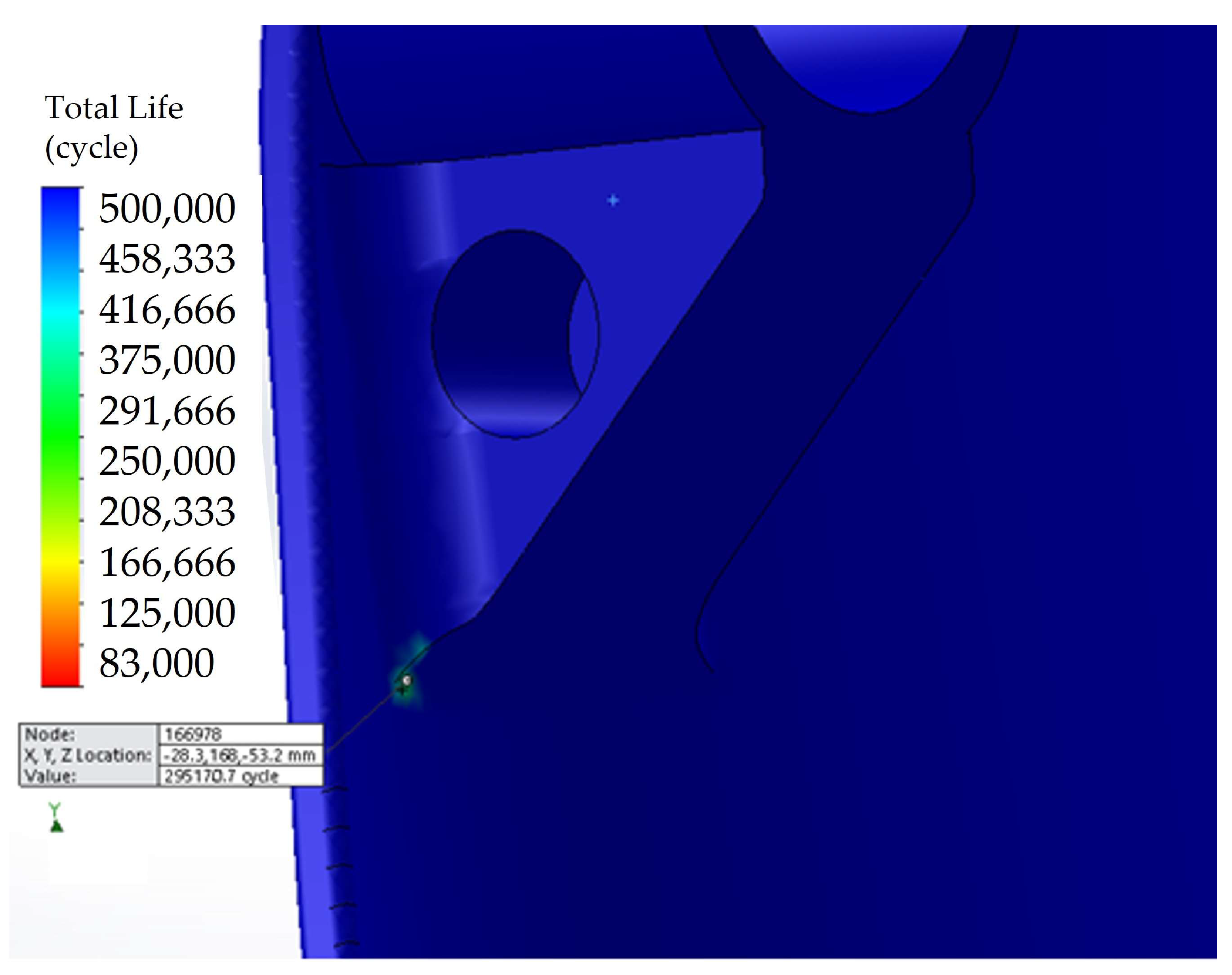
The principle of virtual work is the equivalent of posing the equilibrium equations of our system. We consider that each piece of the prosthesis is a solid body that occupies a volume V in an instant of time t and is subjected to forces b (x, t), which act on the contour Γ. Said forces produce a field of displacements u (x, t), deformations ε (x, t), and stress σ (x, t), which is described in Equation (4) [31].
V δ ε T σ d V = V δ u T b d V + Γ δ u T t d Γ
where the virtual field of deformations, in Voigt notation, is shown in Equation (5).
δ ε = δ ε x   δ ε y   δ ε z   δ ε x y   δ ε x z   δ ε y z T
where εx, εy, and εz are the main diagonal elements of the strain tensor and are called normal strains, whereas εxy, εxz, and εyz are the components outside the main diagonal and are called shear stains. Furthermore, the body forces are presented in Equation (6).
b = b x   b y   b z
In addition, the surface forces acting on the contour of the volume of each object are considered. They are produced by the contact of the parts with the exterior where they are located. The traction vector with three components in the three orthogonal directions is presented in Equation (7).
t = t x   t y   t z
Finally, in Equation (4), the stress term is described, and we consider that the mass and surface forces act on components. We can present the Cauchy stress tensor for a differential volume. Assuming a linear elastic constitutive law, stress and strains are calculated with Equation (8).
σ i j = E ( 1 + ν ) ε i j + ν ( 1 2 ν )   δ i j   ε k k
where E is the elastic modulus and ν is Poisson’s ratio. σx, σy, and σz are the main diagonal elements of the stress tensor and are called normal stresses; τxy, τxz, and τyz, are the components outside the main diagonal and are shear stresses, which are composed of in-plane and out-of-plane stress. Moreover, an equivalent acting stress must be computed when there is more than one stress component. For that purpose, the von Mises criterion is described in Equation (9).
σ f N = ( σ 1 σ 2 ) 2 + ( σ 2 σ 3 ) 2 + ( σ 3 σ 1 ) 2 2
where σi is the normal stress parallel to each of the three principal axes, N is the security factor, and σf is the yield stress.

2.4. Fatigue

On the other hand, if a component is subjected to fluctuating stresses, to predict life, the stress–life method, σ-Nf, can be used, where σf is stress and Nf is the number of cycles to failure. Their relation is described by the Basquin rule, which is shown in Equation (10).
N f = A σ f m
where A and m are material constants. Furthermore, the Miner–Palmgreen damage rule is the simplest but most widely used accumulated damage model [26]. It says that if there are different events ck at a stress σk and the average number of cycles Ni to produce failure at a stress σi, then the damage fraction C given by an event k is given by Equation (11).
C = k = 1 i σ k n k σ i N i 1
which represents the sum of the individual contribution of the product stress and cycles in each event k. Then, C is the fraction of life consumed by exposure to k cycles at different stress levels. With that in mind, we adopted the Weavers and Durance [22] loading scheme for modeling the prosthesis housing.
Moreover, due to the mechanical property uncertainty in composite materials [11], tensile tests were performed to establish rupture stress and elastic modulus for the housing material. An MTS Bionix model 370.02 universal testing machine equipped with a 25 kN load cell was used at a 2 mm/min load rate. Displacement was acquired with an MTS 634.12F-25 extensometer. The MTS suite software was used for displacement control and data collection.

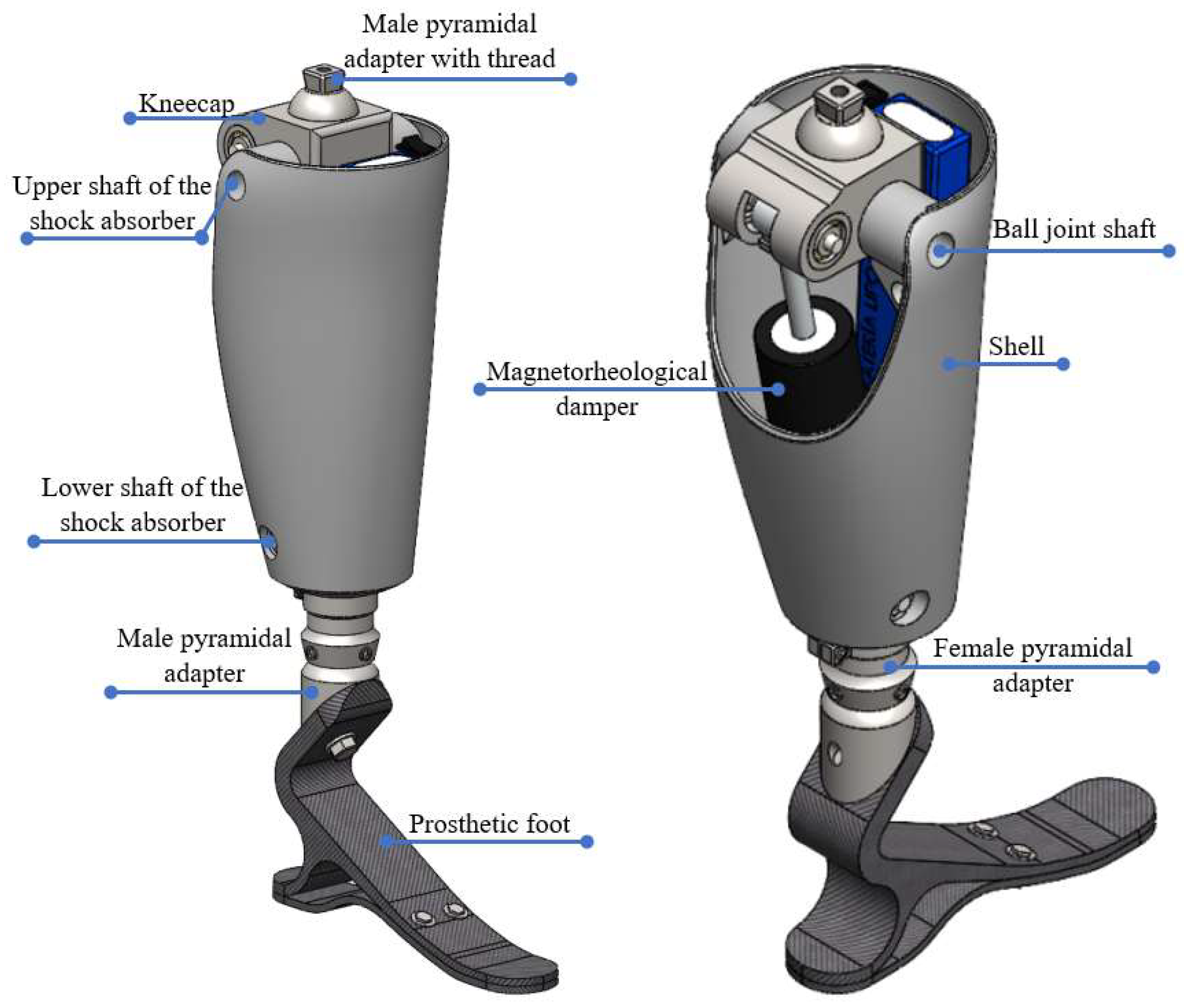
2.5. CAE Implementation

The selected geometry was implemented in SolidWorks. Figure 2 shows the CAD model of the 0.45 m height transfemoral prosthesis prototype without the top socket according to the measurement taken of the exemplary amputee patient.
The male pyramidal adapter with a thread holds the stump’s socket. This adapter is connected to the kneecap that, through its shaft, allows the rotation of the knee joint. The axis of the kneecap connects to the housing that shapes the amputated limb and covers the actuator. In contrast, the upper axis of the shock absorber is attached to the MR actuator that is actuated to rotate the prosthetic joint. On the other hand, the lower shaft of the shock absorber secures the MR actuator to the lower part of the housing. Finally, the bottom of the housing is attached to the pyramidal adapters, both female and male, connecting the socket, and from there, it connects to the prosthetic foot. The foot is composed of two parts attached by bolts, and in the heel, there is a 10 mm gap between the upper and lower soles to give a deflection cushion.
Moreover, each part was simulated in SolidWorks simulation. For an FEM stress analysis, the mesh [26] was constructed with tetrahedral solid elements [17]. Each part was analyzed with a solid and standard mesh type. Table 1 presents the mesh information regarding the elements, nodes, materials, mechanical properties, and manufacturing methods used for each part. Mesh refinement around fillets, supports, transitions, and holes was performed to account for the steeper stress gradient in such areas.
Because the prosthesis must withstand the body’s weight and at the same time be presentable and withstand probable environmentally aggressive conditions, stainless steel was chosen for parts such as adapters and the kneecap [32]. The shafts must be sufficiently small to fit inside the kneecap but must withstand the same loads. Therefore, SAE 4140 with coating was selected [32]. The housing must be lightweight but resistant; we chose a polyester resin reinforced with fiberglass (FG) composite [32] with a 50% fiber content. The prosthetic foot, given its size, can be fabricated on a 3D printer from a composite material that gives highly directional resistance. Therefore, a 3D printed carbon fiber-reinforced composite was chosen given that its strength and elasticity can match those of aluminum [11,33]. In the FEM analysis, the respective loads are added considering the critical force in the balancing phase [15,16,18].
The stress analysis determines the safety factor, N, to know if the material will yield under the acting loads. So, if N is less than 1, the part will fail, and if it is greater than 1, it is guaranteed that the material will not fail and the part will bear the applied loads [26]. On the other hand, fatigue failure occurs when the damage factor reaches 1.

3. Results and Discussion

This section presents the tests and the FEM stress analysis performed for each part.

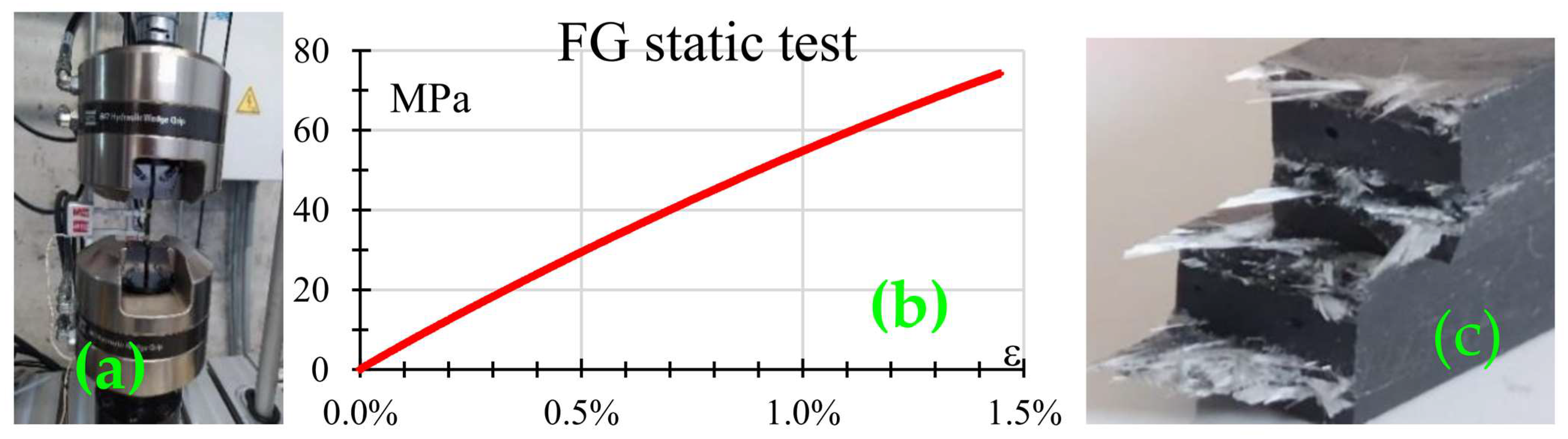
3.1. Fiberglass Mechanical Testing

Three dogbone-type samples, per ASTM 638-IV “Standard Test Method For Tensile Properties Of Plastics”, made from the same fiberglass (FG) batch used for the housing shell, were subjected to tensile testing. Figure 3a shows a sample mounted in the MTS Bionix machine, whereas Figure 3b shows the stress–strain plot for the tests. From the plot, it can be seen that the FG composite behaved in a brittle manner which corresponds to the failure surface depicted in Figure 3c. The rupture stress was 74.3 MPa with a maximum normal strain of 1.4%. Moreover, the failure mechanism corresponds to what is reported for composite materials, namely matrix cracking due to normal stress and fiber pullout [11,34].

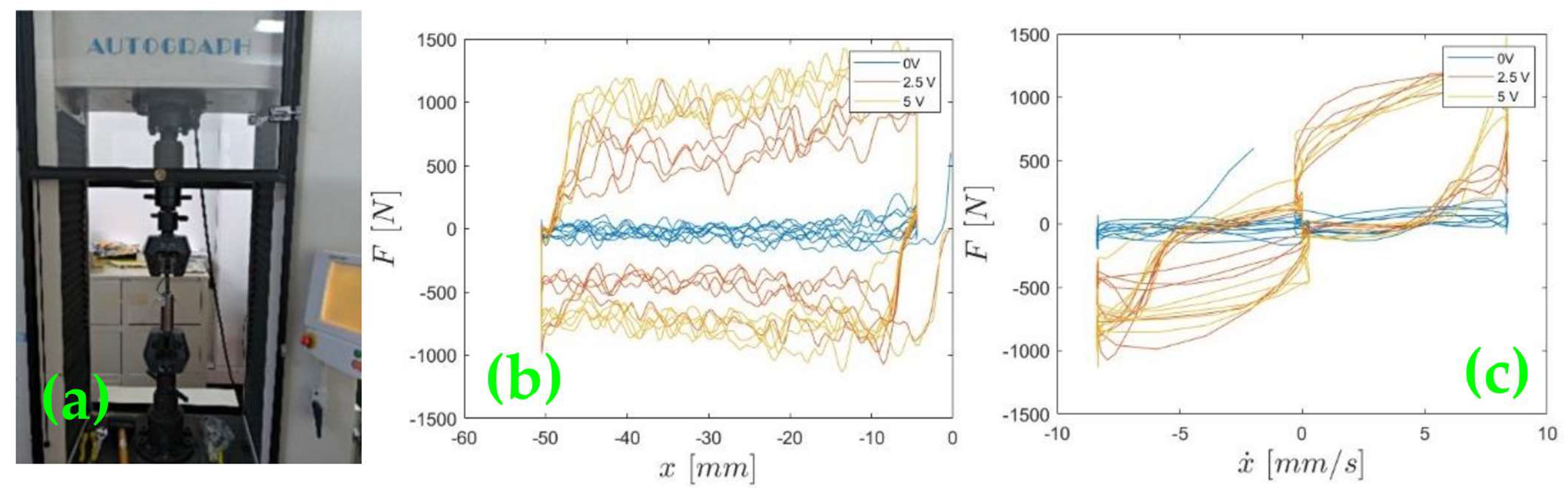
3.2. Mechanical Tests on the Magnetorheological Damper

Uniaxial cyclic tests were performed on the damper to characterize the actuator’s behavior. In this case, an MR damper manufactured by the LORD Corporation [27] was used. An MR damper changes the fluid’s viscosity depending on the supplied voltage. On the Shimadzu Autograph AG-I 250 kN universal testing machine, the behavior of the damping force was determined when the fluid’s viscosity varied depending on the supplied voltage.
Figure 4a shows the damper mounted on the universal testing machine, while Figure 4b shows the force versus displacement plot, and Figure 4c shows the force versus velocity plot for voltages changing from 0 to 5 V. As the applied voltage changed, the damping force also changed. This behavior is due to the magnetic properties of the fluid that depend on the applied voltage which in turn modifies the viscosity. The particles within are aligned, producing a stronger force to displacement, thus dissipating energy. Extensive details about the characterization and control of the MR damper, using parametric and non-parametric models, can be found in [28].

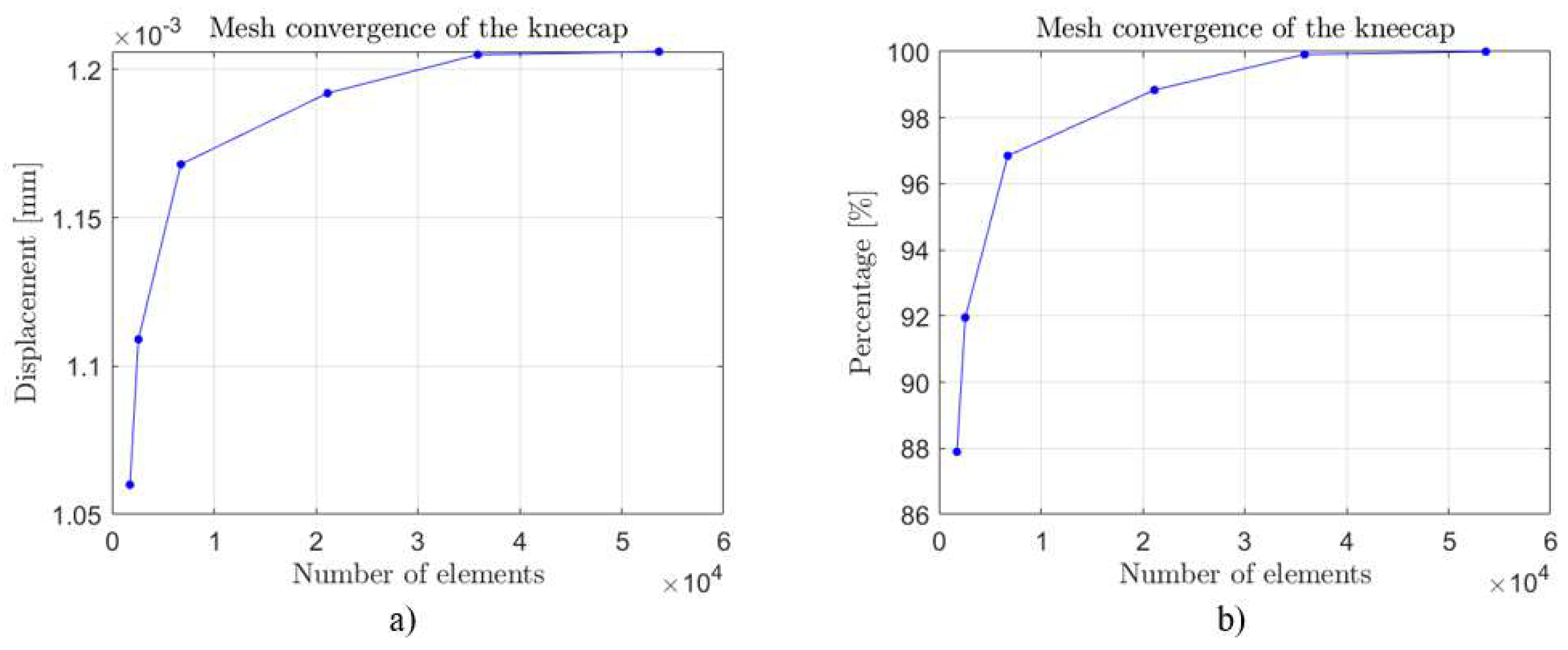
3.3. Mesh Independence

A mesh independence analysis was carried out to observe the effect caused by the element size on the solution [23]; in this case, stress and displacement results were observed. At least five simulations were carried out for each part. Each of the parts was simulated separately, keeping both the loads and the geometry fixed and only lowering the mesh size in each simulation; this resulted in the convergence of the mesh until the final number of nodes and elements was obtained, as shown in Table 1. First, it started with one coarse mesh, with fewer elements representing a solution with less resolution. Then, the number of elements was gradually increased until finalization with a finer mesh, with more elements representing a solution with a higher resolution, especially at places with higher stress gradients. Finally, a representative point was chosen for each mesh size, and the solution was plotted against element size. Because in each part, the results of that mesh analysis were very similar, the results of this mesh analysis were very similar in each part. Exemplary results for the kneecap are shown in Figure 5a, where the convergence of the mesh is observed, for approximately 20000 elements. The result is close to 98.5% of the finest mesh, giving a reliable result for this analysis.
Furthermore, the same type of result for the upper axis of the shock absorber is presented in Figure 5b. The convergence of the displacement is observed for an average element size of 0.0536 mm. This practice allows an adequate use of the mesh since an over- or underestimation of the maximum displacement is avoided. At the same time, a high computational cost is averted [16,26,31].

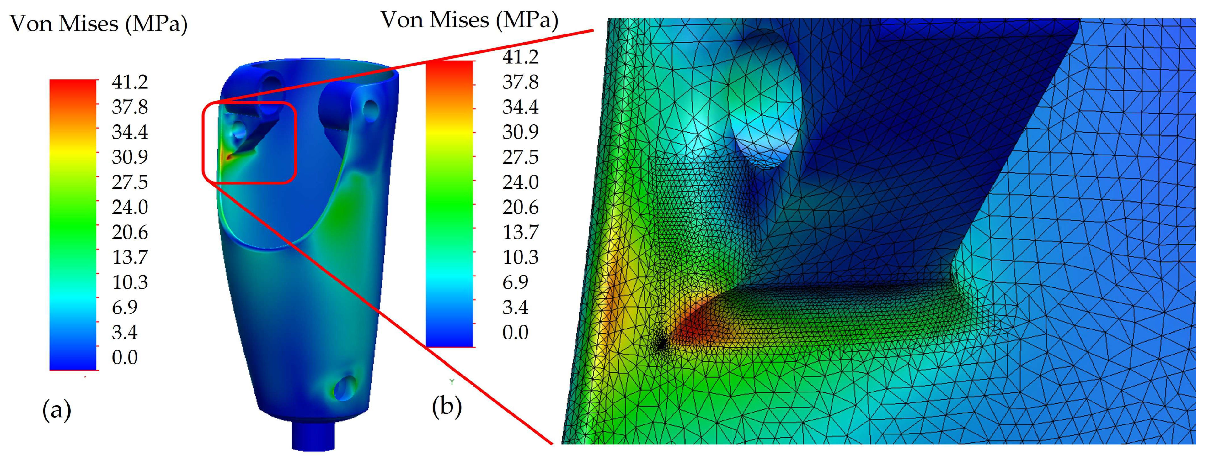
3.4. Male Pyramidal Adapter with Thread
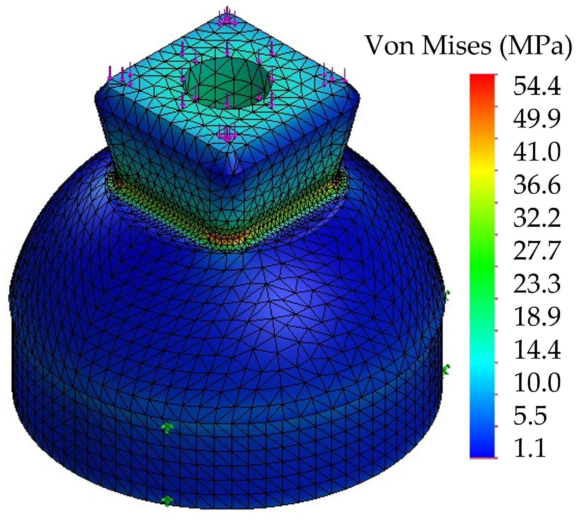
The critical force on the pyramidal male adapter was applied at the top where the socket is attached, while the part of the thread that enters the kneecap was left fixed. The mesh and stress results for the male pyramidal adapter are presented in Figure 6. One can see an expected stress concentration at the base of the pyramid. The yield stress for SS 304 is 400 MPa [32] which gives N = 7.7, so the part will not yield to the applied load.

3.5. Kneecap

The kneecap was built on SAE 304 stainless steel with the critical force applied on the threaded part. The ball joint shaft support was modeled as cylindrical support, while the upper shaft of the shock absorber was modeled as a hinge to visualize the actuator-driven turn. The mesh and the von Mises stress distribution are shown in Figure 7. A safety factor of 10.4 ensures that the part is safe.

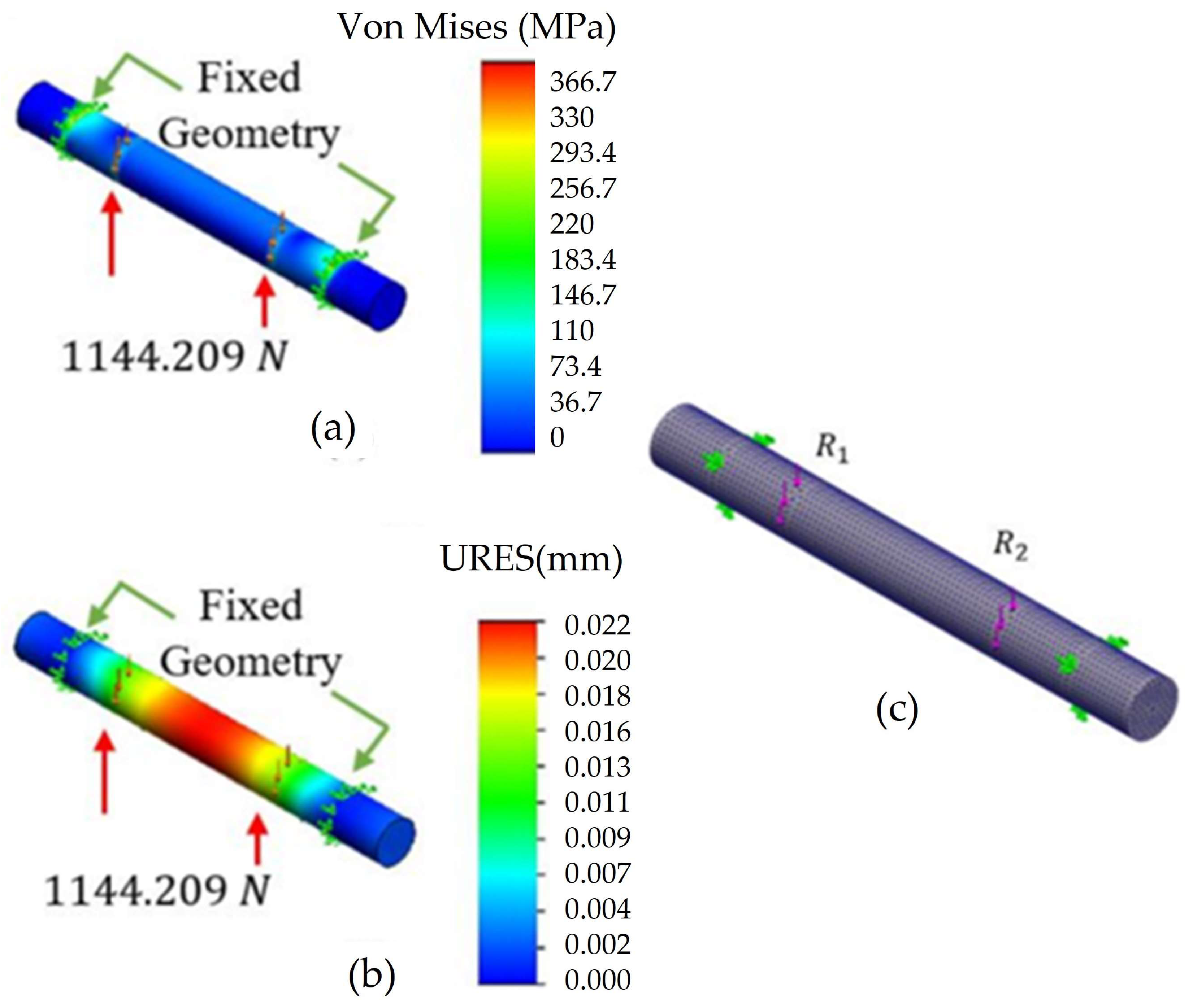
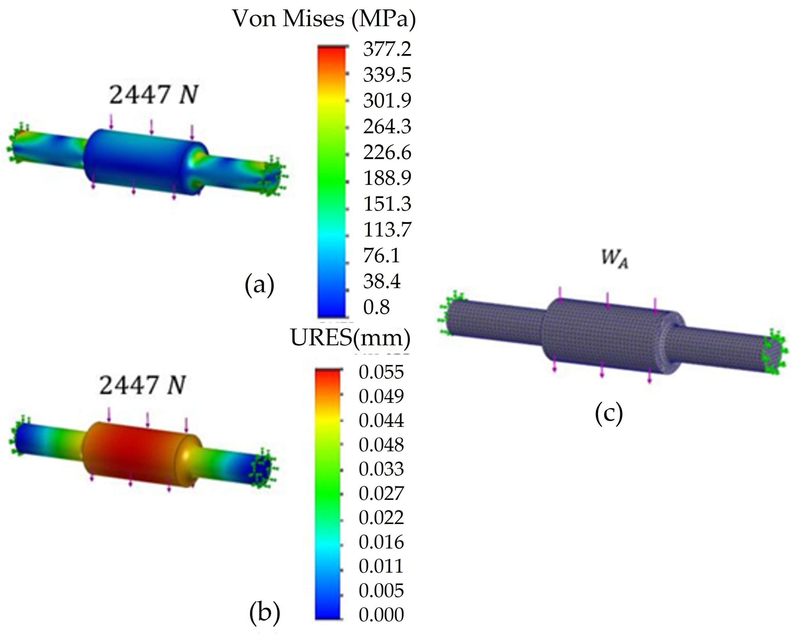
3.6. Ball Joint Shaft

The ball joint shaft was simulated with SAE 4140 steel, with an elastic limit of 750 MPa [32]. It was constrained with a fixed geometry where bearings supported the shaft. Figure 8 shows the mesh details and simulation results for von Mises stress and displacement, where the shaft can withstand the applied force; the lowest safety factor is 2.1. Moreover, the axle has a diameter of 9 mm and a length of 85 mm; the maximum displacement of 0.022 mm is considered acceptable.

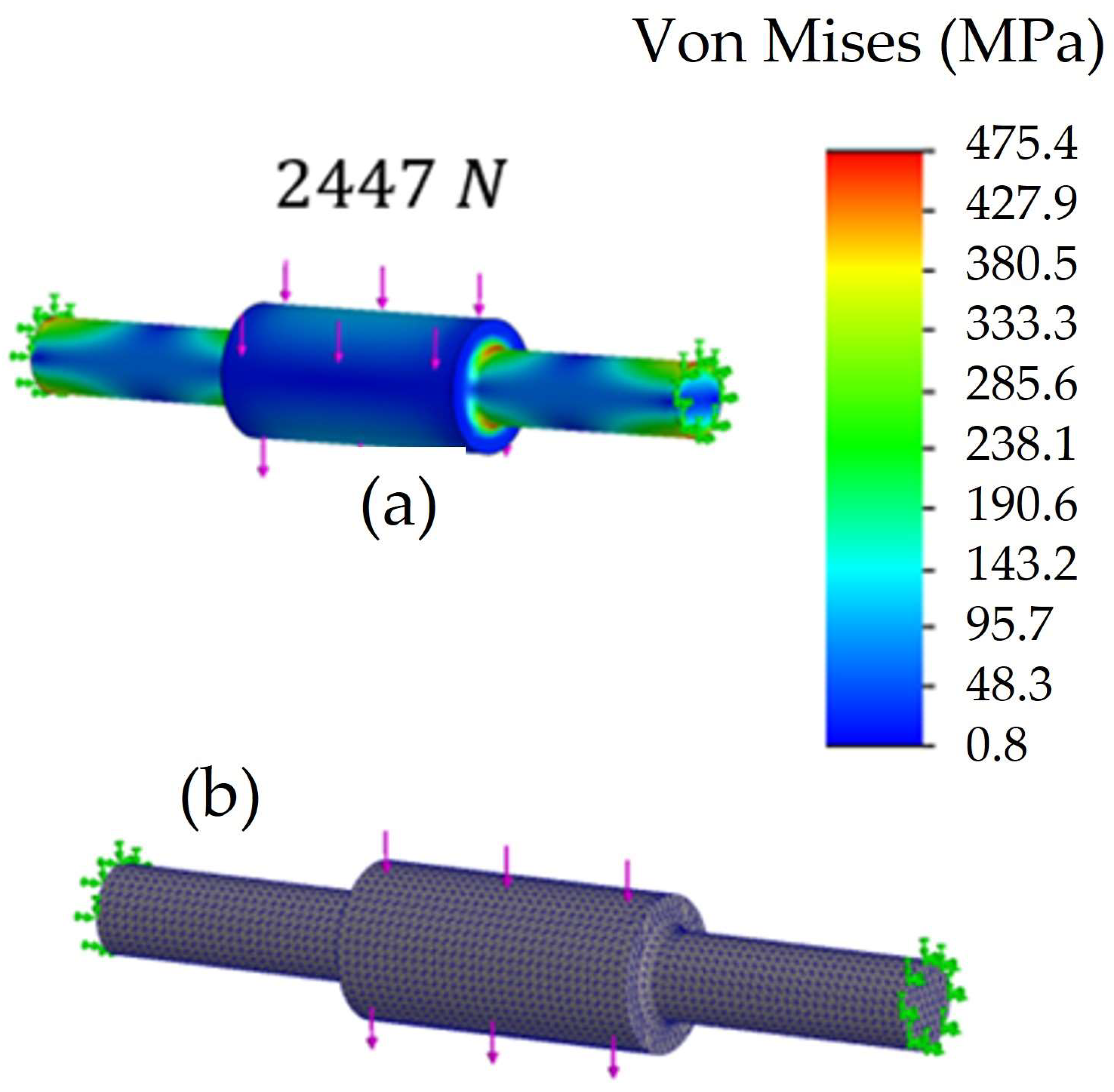
3.7. Upper Axle of the Shock Absorber

The upper shaft of the shock absorber has this shape to adapt to the piston hole of the MR damper at the center of the shaft, and at the ends, it has a smaller diameter to fit a commercial bearing. The material is SAE 4140, which is recommended for shafts [32]. In the simulation, the force of the shock absorber of 2447 N was applied according to its datasheet [27]. There are two fittings at the ends of the shaft for support bearings. Figure 9c depicts the mesh quality and the simulation results for the von Mises stress and displacement. A safety factor of 1.58 guarantees that the material supports the applied load. Regarding the maximum displacement, 0.055 mm is considered negligible in the 70 mm long axle.

3.8. Female Pyramidal Adapter
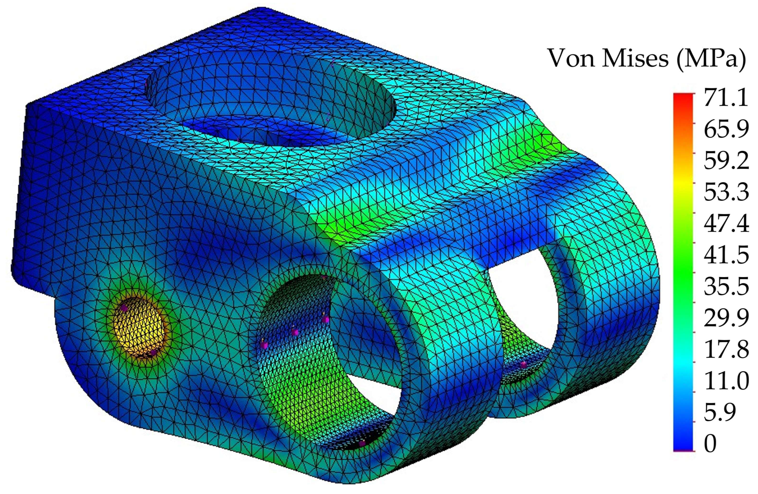
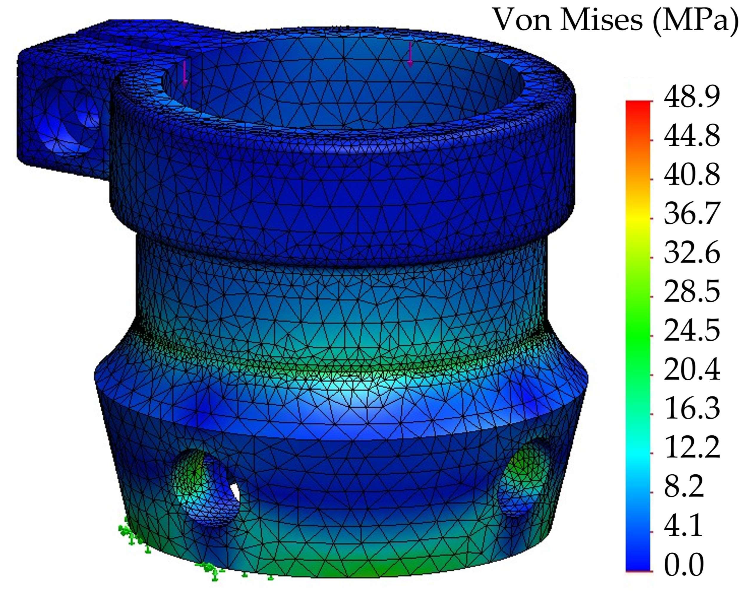
The female pyramidal adapter was fabricated in 304 stainless steel for corrosion resistance and appearance. The critical force was placed where the lower part of the housing holds the clamp, while the section where the male pyramidal adapter of the foot was held with four prisoners was left fixed in the simulation. Figure 10 shows mesh details, and the von Mises stress results in a maximum of 48.9 MPa, which gives a safety factor of 8.16, ensuring the adapter withstands the maximum load applied in the rolling phase.

3.9. Housing

The housing covers the shock absorber and its respective elements that drive the rotation of the prosthetic joint. It was designed to resemble the shape of the leg [20]. Half of the applied force was placed on each surface in contact with the bearing axis in the simulation. The bottom part of the housing, where the female pyramidal adapter is secured, was fixed. The housing was built in FG, as shown in Figure 3. This material was chosen due to its high strength, fracture toughness, and ease of molding into the desired shape.
A first static analysis was run with only the patient’s weight, 980 N, to find a maximum von Mises stress of 14.4 MPa, below the measured 77 MPa ultimate strength. A second scenario was run with the maximum load in the balancing phase, with an acting force of 2940 N. Figure 11a shows the FEM von Mises stress for the housing, where the maximum stress is at the bottom of the upper axle bearing supports. A close-up of that region is shown in Figure 11b over the mesh. The mesh was refined to about 0.5 mm element size on the highly stressed area. The yield strength for FG is 77 MPa, so the safety factor for this part is 1.83.
Furthermore, the maximum equivalent displacement is 0.16 mm at the top of the housing, where the critical force is applied. However, the displacement in the load direction was only 0.07 mm. Therefore, compared to results from [20] in similar housing, the static failure occurred at the bottom, where the female adapter is attached.
Moreover, a buckling analysis was performed on the housing shell for the maximum static load. The analysis was performed assuming the top side was a free end, which we consider the critical scenario. It gave a maximum buckling safety factor of 0.006 on the top supports for the upper shaft. When the buckling factor of safety is lower than 1, buckling is not expected.

3.10. Lower Shaft of the Shock Absorber

The lower shaft of the shock absorber was built with SAE 4140 steel [32] and with the same shape as the upper shaft of the shock absorber. The distributed 2447 N load was applied in the center of the shaft, which is the maximum force of the shock absorber piston. Its ends were set to fix in the place where the bearings go. Figure 12a shows the von Mises stress and Figure 12b the mesh details and the FEM for the lower shaft of the shock absorber. The maximum stress of 475.4 MPa lies in the shoulder from the support to the bearing load center. A safety factor of 1.58 ensures that the material holds the applied load. The maximum displacement was 0.077 mm in the middle of the shaft, which was considered negligible in the 70 mm length. This shaft has the same diameter as the upper axle of the shock absorber.

3.11. Prosthetic Foot

The prosthetic foot holds the male pyramidal adapter on top. The prosthetic foot was built in a composite material with continuous carbon fiber reinforcement and Onyx matrix printed in a Markforged Two composite printer. Onyx is a composite itself made of nylon and short carbon fiber produced by Markforged (Boston, MA, USA). The printer uses the novel technique of fiber deposition modeling (FDM), which can produce highly customized plastic parts at a low cost and match aluminum’s strength and stiffness [11]. According to Parrado and Narváez [35], AM could close the gap between topological optimization and manufacturing. Such a concept was materialized here.
The height of the foot is 150 mm, and it has a 10 mm gap between the bottom of the heel and the upper side of the sole for a deformation cushion on each step. The force was applied to the top end of the male pyramidal adapter. Both the back of the heel and the tip of the foot were fixed on the ground. Although the foot is composed of two parts, it was simulated as two parts with bonded contact with the male pyramidal adapter on top with bonded contact as well. The simulation results are presented in Figure 13.
Although the foot was made of an FDM composite, which is highly orthotropic, besides the inherent anisotropy of AM materials, the material model used was isotropic linear elastic. In the literature, there are data for the combination of printing parameters and bulk mechanical properties [33]. Additionally, there is evidence that a bulk solution can be sufficient to simplify the simulation [11]. The FEM result gives a maximum von Mises stress of 188 MPa that, compared with the material’s elastic limit, 338 MPa [33], gives a safety factor of 1.8, ensuring the part will not fail under static loading. As for the displacement, the maximum was 1.4 mm at the top of the male pyramidal adapter for the displacement. According to Castro [16], 10 mm is the maximum allowed displacement in a prosthesis.

3.12. Fatigue Analysis

Using the Basquin rule, Equation (10), the material constants for the housing are A = 180.1 and n = −0.119 for FG [36]. The housing was the component chosen to perform the stress–life analysis. So, two fatigue scenarios were considered. First, the maximum load was applied at a load inversion ratio of 0.1, giving a life beyond 500,000 cycles. This life value was calculated with the maximum considered force. That scenario considers the patient landing on the prosthetic leg from a height of 0.2 m. The second scenario followed the loading scheme described in [22]. This means we did not consider traction loading, only compressive loading. Figure 14 shows that the number of cycles required to produce failure exceeds the 500,000-cycle limit used in the study. However, the base for the upper axis experiences the highest stresses, as seen in Figure 10, which causes life to drop to 295,170 cycles.
Our stress–life results are lower than what was reported by Mankai et al. [20]. They reported 2.3 M cycles to failure in a carbon composite housing, which is a more expensive material than FG. Additionally, Wevers [22] reported a life between 370,000 and 460,000 cycles but for half of the simulated load in this study. However, the fatigue data [36] for the housing material were unavailable beyond 500,000 cycles, so it cannot be realistically modeled beyond that point. A recent study [37] performed fatigue for more than 2 million cycles, though for R = −1 and R = 0.1, which is a more severe loading case than what we have. Therefore, one could argue that life could be longer for the compression–compression case loading (R = −1) of this prosthesis.

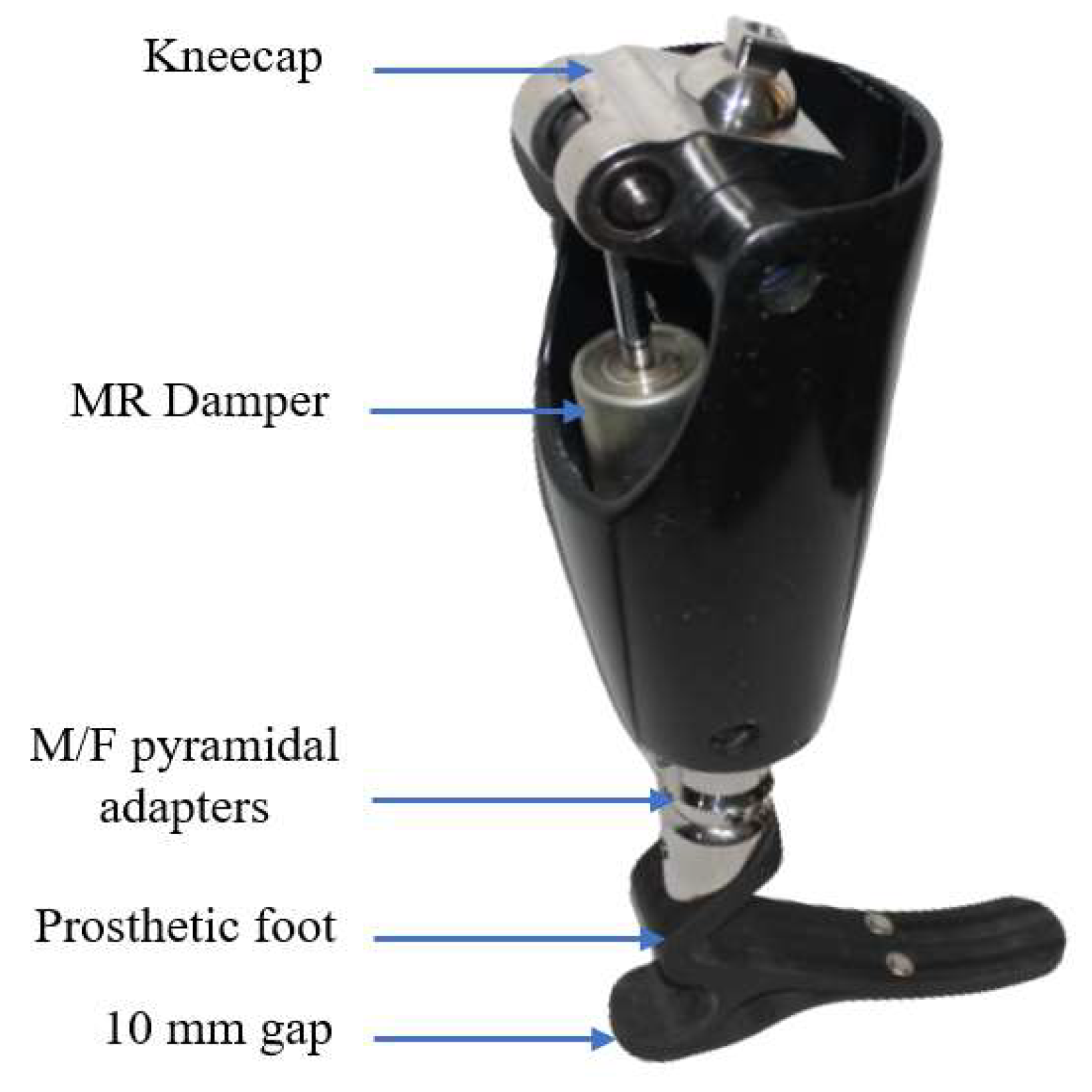
3.13. Built Prosthetic Leg

Figure 15 shows the rear view of the prosthetic leg as built. The kneecap acts as a rocker supported by the MR damper to absorb the applied force. In addition, a 10 mm gap between the bottom part of the foot and the top part of the insole is observed. This gap gives a deformation cushion to help absorb the applied force. Finally, it can be seen how the male pyramidal adapter is the part that will attach to the customized socket according to the patient’s needs.
Finally, safety factors in this study are comparable to the ones obtained in [2,22].

4. Conclusions

Stress analysis for a transfemoral prosthesis was carried out through simulation by FEM in the balance phase for a person of a maximum of 100 kg during the human gait. The prosthesis includes an MR damper that conditions the reaction force with the load speed application. The simulation allowed us to know the results of both tension and displacements and that the design fulfills the specifications without oversizing. Furthermore, using the MR damper helps dissipate energy, reducing the acting loads on the housing shell.
The FEM simulation carried out for a prosthetic leg returned displacements and stress. It is observed that the von Mises stress values determined by FEM do not exceed the yield stress for each material. This guarantees that the parts will not fail during operation under the projected failure mechanisms. The displacements calculated do not affect the functioning of the prosthesis and are negligible with respect to the dimensions of each part. The materials selected for each piece are appropriate for hygiene, resistance, presentation, and corrosion, considering that the prosthesis will be exposed to adverse environmental conditions. Furthermore, a fatigue analysis for the most critically loaded component revealed that the number of cycles to failure is 295,107.
A generic off-the-shelf transfemoral prosthetic leg was designed and built. Blueprints (in PDF format) (Supplementary Materials) and *.STL files for parts are available (on the web version of the article) for anyone to reproduce the prosthesis. So, we hope the waiting time, or the cost, for a patient to obtain a prosthesis should be lower than before as we provide a ready-to-build design. The design leaves only the need to customize the adapter socket between the limb and the prosthetic leg for each patient. Furthermore, the leg was built using different processes, including subtractive manufacturing for the shafts, adapters, and kneecap; composite molding for the housing, and the novel composite material AM for the foot. As with any design, geometric or shape deviation from initial specifications may induce unwanted results; the prosthetic foot also must be built following printing direction, cellular infill, and volume fiber fraction, among other factor choices as described on the blueprints. Shortly, as 3D printers become even more available and offer a larger printing envelope, parts such as the housing could also be manufactured with that technique.
Finally, in this version, the housing shell was manufactured as a laminated composite. With 3D printers becoming even more popular, cheaper, and able to print in larger formats, the housing shell could be manufactured in a 3D composite printer. This possibility would make it easier to change the small radii where the highest stress concentration occurs, hence improving the life of the prosthesis.

Supplementary Materials

The following supporting information can be downloaded at: https://www.mdpi.com/article/10.3390/inventions8010036/s1. The web version of the article contains blueprints (as *.PDF) and *.STL files for the prosthesis’ parts.

Author Contributions

Funding: C.H.V.-N., M.B. and P.A.O.-H.; conceptualization, C.H.V.-N., M.B. and P.A.O.-H.; methodology S.M.-V., Z.A.M.-P. and J.G.D.-R.; software, S.M.-V. and Z.A.M.-P.; validation, J.G.D.-R.; formal analysis S.M.-V., Z.A.M.-P. and J.G.D.-R.; investigation, S.M.-V., Z.A.M.-P., C.H.V.-N. and P.A.O.-H.; resources, S.M.-V., Z.A.M.-P. and P.A.O.-H.; data curation, S.M.-V., Z.A.M.-P., P.A.O.-H. and J.G.D.-R.; writing—original draft preparation, S.M.-V., Z.A.M.-P., P.A.O.-H. and J.G.D.-R.; writing—review and editing, All; visualization, S.M.-V. and Z.A.M.-P.; supervision, M.B. and J.G.D.-R.; project administration, C.H.V.-N.; funding acquisition, C.H.V.-N. and M.B. All authors have read and agreed to the published version of the manuscript.

Funding

Universidad Santo Tomás (Colombia) and Universidade de São Paulo (Brazil).

Data Availability Statement

Data is available upon request.

Acknowledgments

The authors are grateful for support from the academic vice-president office, Santo Tomas University, from the XII call for research projects with minute 163, 5 February 2020.

Conflicts of Interest

The authors declare no conflict of interest.

References

  1. Ocampo, M.L.; Henao, L.M.; Vasquez, L. Amputación de Miembro Inferior; Cambios Funcionales y Actividad Física: Bogotá, Colombia, 2010. [Google Scholar]
  2. Valencia Aguirre, F.V.; Mejía Echeverria, C.D.; Erazo-Arteaga, V. Desarrollo de una prótesis de rodilla para amputaciones transfemorales usando herramientas computacionales. CAD CAE CAM Rev. UIS 2017, 16, 23–34. [Google Scholar] [CrossRef] [Green Version]
  3. Quintero Quiroz, C.; Jaramillo Zapata, A.; De Ossa Jiménez, M.T.; Villegas Bolaños, P.A. Estudio descriptivo de condiciones del muñón en personas usuarias de prótesis de miembros inferiores. Rev. Colomb. De Médicina Física Y Rehabil. 2015, 25, 94–103. [Google Scholar] [CrossRef] [Green Version]
  4. Konya, M.N.; Verim, Ö. Numerical Optimization of the Position in Femoral Head of Proximal Locking Screws of Proximal Femoral Nail System; Biomechanical Study. Balkan Med. J. 2017, 34, 425–431. [Google Scholar] [CrossRef] [PubMed]
  5. Ocaña, E. Diseño y Análisis de Esfuerzos de Prótesis Transfemoral Pasiva Basada en Mecanismo de Cuatro Barras. Master’s Thesis, Centro de Tecnología Avanzada CIATEQ, Villahermosa, Mexico, 2018. [Google Scholar]
  6. Sterkenburg, A.J.; Van der Stelt, M.; Koroma, A.R.; Van Gaalen, M.D.; Van der Pols, M.J.; Grobusch, M.P.; C.H. Slump, C.H.; Maal, T.J.J.; Brouwers, L. Quality of life of patients with 3D-printed arm prostheses in a rural area of Sierra Leone. Heliyon 2021, 7, e07447. [Google Scholar] [CrossRef]
  7. Luengas-Contreras, L.A.; Camargo-Casallas, E.; Guardiola, D. Modelagem e simulaāo da marcha protética usando modelo em 3D de uma prótese transtibial. Rev. Cienc. Salud 2018, 16, 82. [Google Scholar] [CrossRef] [Green Version]
  8. Portnoy, S.; Yizhar, Z.; Shabshin, N.; Itzchak, Y.; Kristal, A.; Dotan-Marom, Y.; Siev-Ner, I.; Gefen, A. Internal mechanical conditions in the soft tissues of a residual limb of a trans-tibial amputee. J. Biomech. 2008, 41, 1897–1909. [Google Scholar] [CrossRef]
  9. Tao, Z.; Ahn, H.-J.; Lian, C.; Lee, K.-H.; Lee, C.-H. Design and optimization of prosthetic foot by using polylactic acid 3D printing. J. Mech. Sci. Technol. 2017, 31, 2393–2398. [Google Scholar] [CrossRef]
  10. Tamayo, J.A.; Riascos, M.; Vargas, C.A.; Baena, L.M. Additive manufacturing of Ti6Al4V alloy via electron beam melting for the development of implants for the biomedical industry. Heliyon 2021, 7, e06892. [Google Scholar] [CrossRef]
  11. Díaz-Rodríguez, J.G.; Pertúz-Comas, A.D.; González-Estrada, O.A. Mechanical properties for long fibre reinforced fused deposition manufactured composites. Compos. B Eng. 2021, 211, 108657. [Google Scholar] [CrossRef]
  12. Veiga, F.; Bhujangrao, T.; Suárez, A.; Aldalur, E.; Goenaga, I.; Gil-Hernandez, D. Validation of the Mechanical Behavior of an Aeronautical Fixing Turret Produced by a Design for Additive Manufacturing (DfAM). Polymers 2022, 14, 2177. [Google Scholar] [CrossRef]
  13. Veiga, F.; Suárez, A.; Aldalur, E.; Goenaga, I.; Amondarain, J. Wire Arc Additive Manufacturing Process for Topologically Optimized Aeronautical Fixtures. 3D Print Addit. Manuf. 2021. [Google Scholar] [CrossRef]
  14. Correal Franco, S.; Palacio Delgado, L.J.; Salazar Gómez, I.C. Análisis FEA de prótesis de rodilla policéntrica. Av. En Sist. E Inf. 2006, 3, 35–38. [Google Scholar]
  15. Sánchez, J.; Hernández, R.; Torres, J. The mechanical design of a transfemoral prosthesis using computational tools and design methodology. Ing. E Investig. 2012, 3, 14–18. [Google Scholar]
  16. Castro-Junco, J.O. Diseño de Prótesis Transfemoral. Master’s Thesis, Universidad de América, Bogota, Colombia, 2018. [Google Scholar]
  17. Cely, M.; Robledo, A. Análisis por elementos finitos aplicados a separadores de cadera como predictor en el diseño de instrumental quirúrgico. Dyna 2011, 78, 213–219. [Google Scholar]
  18. Erazo Bravo, M.I.; Mera Otoya, E.P. Diseño e Implementación de un Prototipo de Prótesis Transtibial con Amortiguamiento Activo Mediante la Investigación del Comportamiento de Materiales Magnetoreológicos Bajo Diferentes Campos Magnéticos. Master’s Thesis, Universidad de Fuerzas Armadas ESPE, Latacunga, Ecuador, 2017. [Google Scholar]
  19. Fábrica, G.; Peña, I.; Silva-Pereyra, V.; Ramos-Arim, V. Aprovechamiento de energía, cinemática y estabilidad en la marcha de un paciente con amputación transfemoral sin abordaje de rehabilitación. Rev. De La Fac. De Med. 2018, 66, 59–68. [Google Scholar] [CrossRef]
  20. Mankai, W.; Brahim, S.B.; Smida, B.B.; Cheikh, R.B.; Chafra, M. Mechanical behavior of a lower limb prosthetic socket made of natural fiber reinforced composite. J. Eng. Res. 2021, 9, 269–277. [Google Scholar] [CrossRef]
  21. López-Gualdrón, C.I.; Bautista-Rojas, L.E.; Machuca-Gelvez, J.A. Reconstrucción 3D para el desarrollo de prótesis de miembro inferior. Rev. UIS Ing. 2020, 19, 73–85. [Google Scholar] [CrossRef]
  22. Wevers, H.W.; Durance, J.P. Dynamic testing of below-knee prosthesis. Prosthet. Orthot. Int. 1987, 11, 117–123. [Google Scholar] [CrossRef] [Green Version]
  23. Jelačić, Z.; Ustamujić, F.; Dedić, R.; Husnić, Ž. Development of 3D Printed Transfemoral Prosthetic Leg with Actuated Joints. In Proceedings of the New Technologies, Development and Application V, Sarajevo, Bosnia and Herzegovia, 23–25 June 2022; pp. 209–219. [Google Scholar] [CrossRef]
  24. Ospina-Henao, P.A.; Valencia, C.H.; Becker, M.; Mora, P.Z.A.; Vásquez, S.M. Modeling of a Leg and Knee System for the Analysis of Human Gait by Means of State Feedback Control. Front. Artif. Intell. Appl. 2020, 322, 288–301. [Google Scholar] [CrossRef]
  25. Valencia, C.H.; Vellasco, M.; Tanscheit, R.; Figueiredo, K.T. Magnetorheological Damper Control in a Leg Prosthesis Mechanical. In Robot Intelligence Technology and Applications; Springer: Berlin/Heidelberg, Germany, 2015; Volume 3, pp. 805–818. [Google Scholar] [CrossRef]
  26. Kurowski, P. Engineering Analysis with SOLIDWORKS Simulation, 1st ed.; SDC Publications: Mission, KS, USA, 2018. [Google Scholar]
  27. LORD Corporation. RD-8040-1 and RD-8041-1 Dampers; Technical data; LORD Corporation: Cary, NC, USA, 2009. [Google Scholar]
  28. Rodríguez-Torres, A.; López-Pacheco, M.; Morales-Valdez, J.; Yu, W.; Díaz, J.G. Robust Force Estimation for Magnetorheological Damper Based on Complex Value Convolutional Neural Network. J. Comput. Nonlinear Dyn. 2022, 17, 121003. [Google Scholar] [CrossRef]
  29. Zuly, A.M.P.; Vásquez, S.M.; Valencia, C.H.; Carreño Zagarra, J.J.; Becker, M.; Ospina Henao, P.A. Discrete control of transfemoral prostheses for human walking with magnetorheological compensation. J. Phys. Conf. Ser. 2022, 2307, 012017. [Google Scholar] [CrossRef]
  30. Taylor, J. Classical Mechanics; University Science Books: Melville, NY, USA, 2005. [Google Scholar]
  31. Barbero, E.J. Finite Element Analysis of Composite Materials Using ANSYS, 2nd ed.; CRC Press: Boca Raton, FL, USA, 2013. [Google Scholar]
  32. Ashby, M.F. Materials Selection in Mechanical Design, 4th ed.; Elsevier: Oxford, UK, 2011. [Google Scholar] [CrossRef] [Green Version]
  33. González-Estrada, O.A.; Pertuz Comas, A.D.; Díaz Rodríguez, J.G. Monotonic load datasets for additively manufactured thermoplastic reinforced composites. Data Brief 2020, 29, 105295. [Google Scholar] [CrossRef] [PubMed]
  34. Pertuz-Comas, A.D.; Díaz, J.G.; Meneses-Duran, O.J.; Niño-Álvarez, N.Y.; León-Becerra, J. Flexural Fatigue in a Polymer Matrix Composite Material Reinforced with Continuous Kevlar Fibers Fabricated by Additive Manufacturing. Polymers 2022, 14, 3586. [Google Scholar] [CrossRef] [PubMed]
  35. Parrado-Agudelo, J.Z.; Narváez-Tovar, C. Mechanical characterization of polylactic acid, polycaprolactone and Lay-Fomm 40 parts manufactured by fused deposition modeling, as a function of the printing parameters. ITECKNE 2019, 16, 25–31. [Google Scholar] [CrossRef] [Green Version]
  36. EL-Wazery, M.S.; EL-Elamy, M.I.; Zoalfakar, S.H. Mechanical properties of glass fiber reinforced polyester composites. Int. J. Appl. Sci. Eng. 2016, 14, 121–131. [Google Scholar] [CrossRef]
  37. Sun, X.; Li, Y.; Engler-Pinto, C.; Huang, L.; Huang, S.; Li, Z.; Tang, H.; Bao, Z.; Cui, H.; Zeng, D.; et al. Characterization and modeling of fatigue behavior of chopped glass fiber reinforced sheet molding compound (SMC) composite. Int. J. Fatigue 2022, 156, 106647. [Google Scholar] [CrossRef]
Figure 1. Free body diagram in the rolling phase.
Inventions 08 00036 g001
Figure 2. Front and posterior view of the transfemoral prosthesis.
Inventions 08 00036 g002
Figure 3. Results of FG mechanical testing: (a) test setup; (b) stress–strain plot; (c) close-up of ruptured sample.
Inventions 08 00036 g003
Figure 4. Results of the mechanical tests of the magnetorheological damper: (a) test setup; (b) force–displacement plot; (c) force-velocity plot.
Inventions 08 00036 g004
Figure 5. Exemplary results of mesh convergence: (a) results for kneecap displacement as a function of the number of elements; (b) displacement in the upper axis of the shock absorber as a function of the number of elements.
Inventions 08 00036 g005
Figure 6. Stress results for the male pyramidal adapter with thread.
Inventions 08 00036 g006
Figure 7. Stress analysis for the kneecap.
Inventions 08 00036 g007
Figure 8. FEM analysis for the ball joint shaft showing where the supports were placed: (a) von Mises stress; (b) displacement; (c) mesh details.
Inventions 08 00036 g008
Figure 9. FEM analysis for the upper axle of the shock absorber: (a) von Mises stress; (b) displacement; (c) mesh details.
Inventions 08 00036 g009
Figure 10. Stress analysis for the female pyramidal adapter.
Inventions 08 00036 g010
Figure 11. FEM analysis for the housing: (a) stress; (b) close-up of the area with the most stress, including mesh details.
Inventions 08 00036 g011
Figure 12. Lower shaft of the shock absorber: (a) Von Mises stress; (b) Mesh details.
Inventions 08 00036 g012
Figure 13. Static analysis for the prosthetic foot: (a) von Mises stress; (b) displacement; (c) mesh details.
Inventions 08 00036 g013
Figure 14. Close-up of the cycle number map for the housing failure.
Inventions 08 00036 g014
Figure 15. Rear view of the built prosthetic leg.
Inventions 08 00036 g015
Table 1. Details of nodes, material, mechanical properties, manufacturing method, and mass for each part.
PartNumber of
Elements
Number
of Nodes
MaterialModulus of Elasticity, E (GPa)PoissonManufacturing MethodMass (g)
Male pyramidal adapter with thread49,94272,515304 stainless steel2000.28Machined142
Kneecap 53,66480,941304 stainless steel2000.28Machined660
Ball joint shaft47,52970,038SAE 41402100.28Machined43
Upper shaft of the shock absorber44,98765,898SAE 41402100.28Machined37
Housing shell260,300159,342GRC woven1030.22Laminated composite470
Lower shaft of the shock absorber 44,70165,945SAE 41402100.28Machined37
Female pyramidal adapter57,61790,829304 stainless steel2000.28Machined121
Prosthetic foot group56,93791,0373D carbon composite14.20.2AM414
Disclaimer/Publisher’s Note: The statements, opinions and data contained in all publications are solely those of the individual author(s) and contributor(s) and not of MDPI and/or the editor(s). MDPI and/or the editor(s) disclaim responsibility for any injury to people or property resulting from any ideas, methods, instructions or products referred to in the content.

