Article

VHCF of the 3D-Printed Aluminum Alloy AlSi10Mg

Moscow Aviation Institute, Volokolamskoe Highway 4, 125993 Moscow, Russia
*
Author to whom correspondence should be addressed.
Inventions 2023, 8(1), 33; https://doi.org/10.3390/inventions8010033
Submission received: 13 December 2022 / Revised: 2 January 2023 / Accepted: 3 January 2023 / Published: 30 January 2023
(This article belongs to the Special Issue Innovations in 3D Printing 2.0)

Abstract

:
The paper is focused on the very high cycle fatigue (VHCF) properties of aluminum alloys proceeded in two different technological procedures. The hot-rolled D16T alloy is compared with the selected laser melting (SLM) AlSi10Mg alloy. The fatigue tests were performed at a high frequency (20 kHz) in the laboratory air environment at room temperature. The experimental results showed a significant difference in fatigue strength between hot-rolled and SLM materials. The VHCF properties of AlSi10Mg were more than two times lower than those of D16T in spite of the comparable quasi-static tensile properties. The difference in fatigue properties was explained based on fractographic analysis of fracture surfaces. The morphology of the fracture pattern was qualitatively different. In the case of the hot-rolled alloy, the three clear zones of crack growth could be outlined. The main part of the pattern was covered by quasi-brittle facets that are typical for VHCF fractures in Al alloys. In the case of the SLM material, unregulated structures were found in the microstructure. In some local zones, numerous non-melted particles were observed on the fracture surface. The boundaries of certain layers also played an important role in the fracture. Large, separated surfaces were observed on the fracture pattern. It is important to note that these boundaries were not associated with the layer-by-layer building of the specimen. The distance between such features was significantly larger than the thickness of an individual layer.

1. Introduction

High-strength aluminum alloys are wildly used in the aeronautic industry for skinning aircraft and produce some structural elements subjected to cyclic loading. The devolving of additive manufacturing has made it possible to engage the SLM procedure to produce some real structure components for the aircraft industry. The advantages of SLM technology are a decrease in the number of joints and the possibility to produce elements with quite complex shapes. Such a design strategy allows a gain of mass by several tens of percentage points. Regarding the aircraft industry, this is a very important goal. However, the problem with SLM material is the low cyclic strength of the final product. Progress in this technology has allowed an increase in the quasi-static properties of SLM materials up to the level of traditional technologies, such as extrusion, stamping, etc. However, the low and high cycle fatigue (HCF) properties are still low. The main reason for this is the complex microstructure of SLM materials, which is difficult to control. The properties of the SLM material microstructure affect the laser scanning strategy, the parameters of the laser beams, energy, heat transfer from the meld zone, the parameters of the environment in the chamber, etc. Therefore, to improve the cyclic properties of the material, it is necessary to investigate the nature and mechanisms of fatigue fracture with respect to materials science.
According to modern approaches (McDowell), materials should be investigated as a multi-scale system. Plastic defects and deformation are associated with different structures, such as point defects, linear defects or dislocations, spatial defects, and so on. Several scale levels involve introducing titration from atomic to macroscopic. In other schools [1,2], the three scale levels involve introducing micro-, meso-, and macro-scales [3,4]. Great scientific efforts aim to link these scale levels into one theory, but currently, a clear theory is absent. Materials science is still operating with low cycle fatigue (LCF), HCF, and VHCF regions. The transition from one region to another is not yet clear, and for some metals, such a transition can be found in unusual ways. The regular way is the transition from LCF to HCF and then from HCF to VHCF with a stress amplitude decline. It was found that for metals, the transition from VHCF to LCF or HCF depends on the ratio R = σ−10.2, where σ−1 is the fatigue limit and σ0.2 is the yield strength [5]. The VHCF region is characterized by a principal difference in the crack initiation mechanism. Unlike the LCF or HCF region, the crack under VHCF appears at the subsurface of the material [5,6,7,8,9]. The subsurface crack initiation mechanism is common for different materials, such as steels, titanium alloys, nickel-based alloys, aluminum alloys, and others. The local, micro-scale features of the material providing the subsurface crack initiation may be different, but the subsurface mechanism is the same. It was experimentally shown that for high-strength steels [8], the initiation was associated with non-metallic inclusions, while in the case of a titanium alloy [9], the crack origin was due to flat facets. All these features of the structure do not manifest themselves under LCF or HCF loading. This fact shows that different loading conditions allow the estimation of the fatigue behavior of the material at different scale levels. LCF and HCF mainly represent the macro-scale properties of the material, while VHCF represents the micro-scale fatigue behavior. Since the SLM procedure produces a quite complex micro-structure with different features, the study of VHCF offers a good perspective to investigate the micro-scale fatigue behavior of SLM material. In this study, we focused on a VHC study of AlSi10Mg aluminum alloy and compared it with some already available results on Al alloys [10,11,12,13,14,15].
The study of VHCF properties opens a great opportunity to investigate the basic response of the material to cyclic loading and be engaged to express an analysis of the material state. This paper focuses on two important questions: are there differences in the crack initiation mechanism and growth under VHCF loading for specimens produced by traditional technology and additive manufacturing? Is it possible to use VHCF testing methods to express an analysis of additive manufacturing, and what could the inspection parameters be?

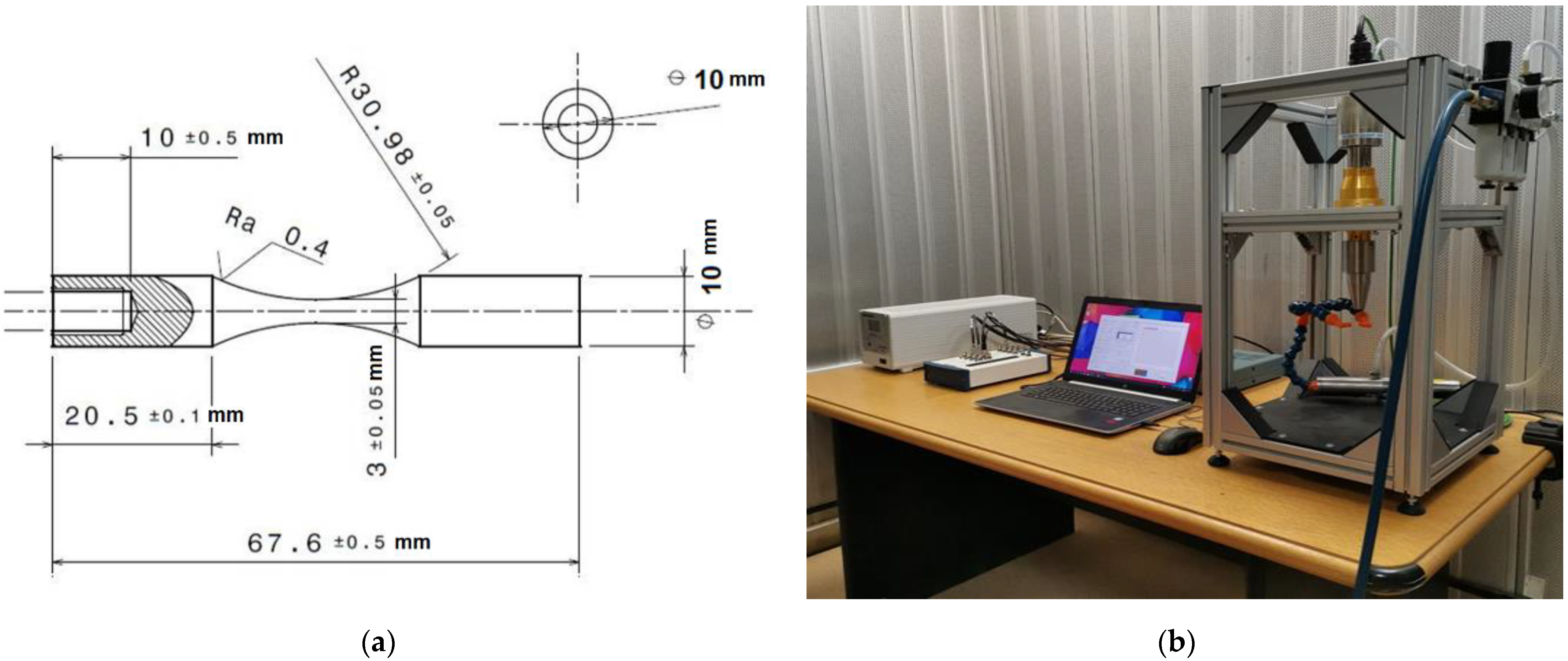
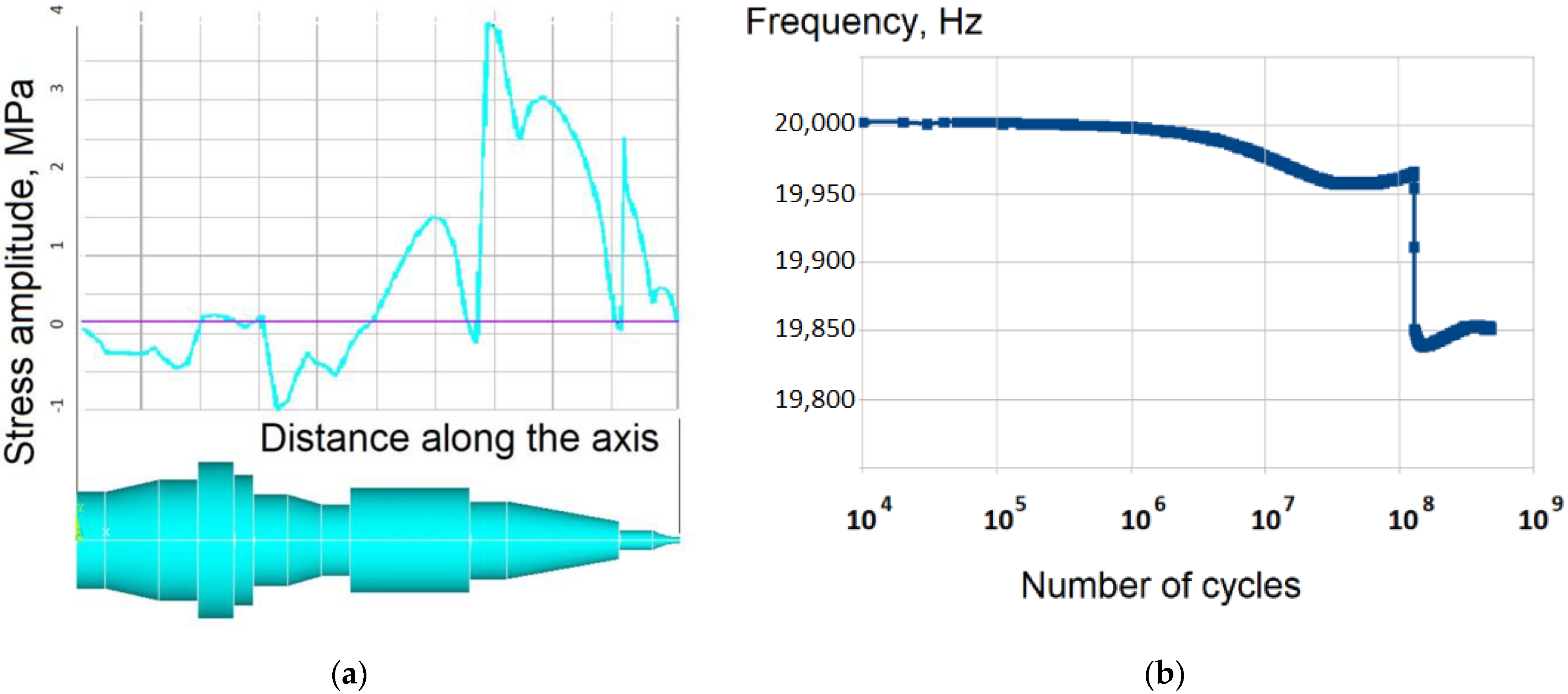
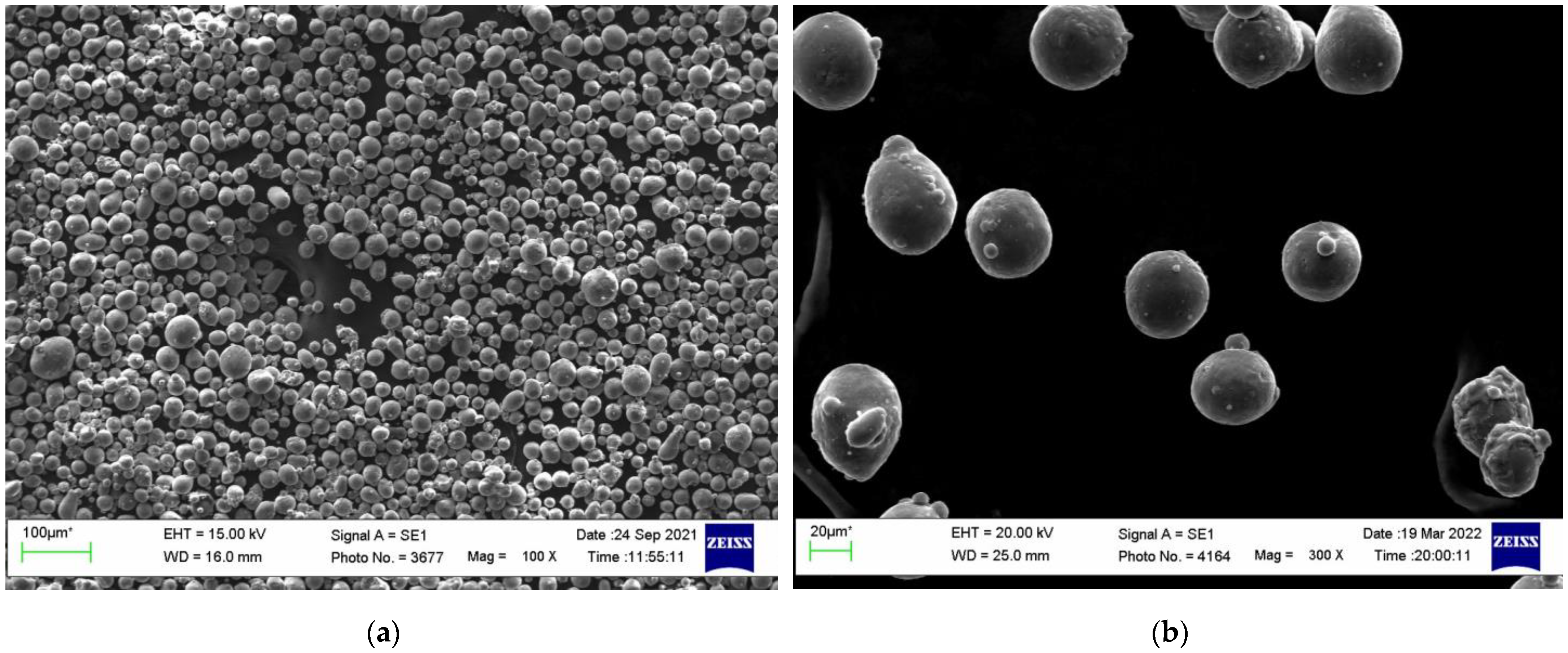
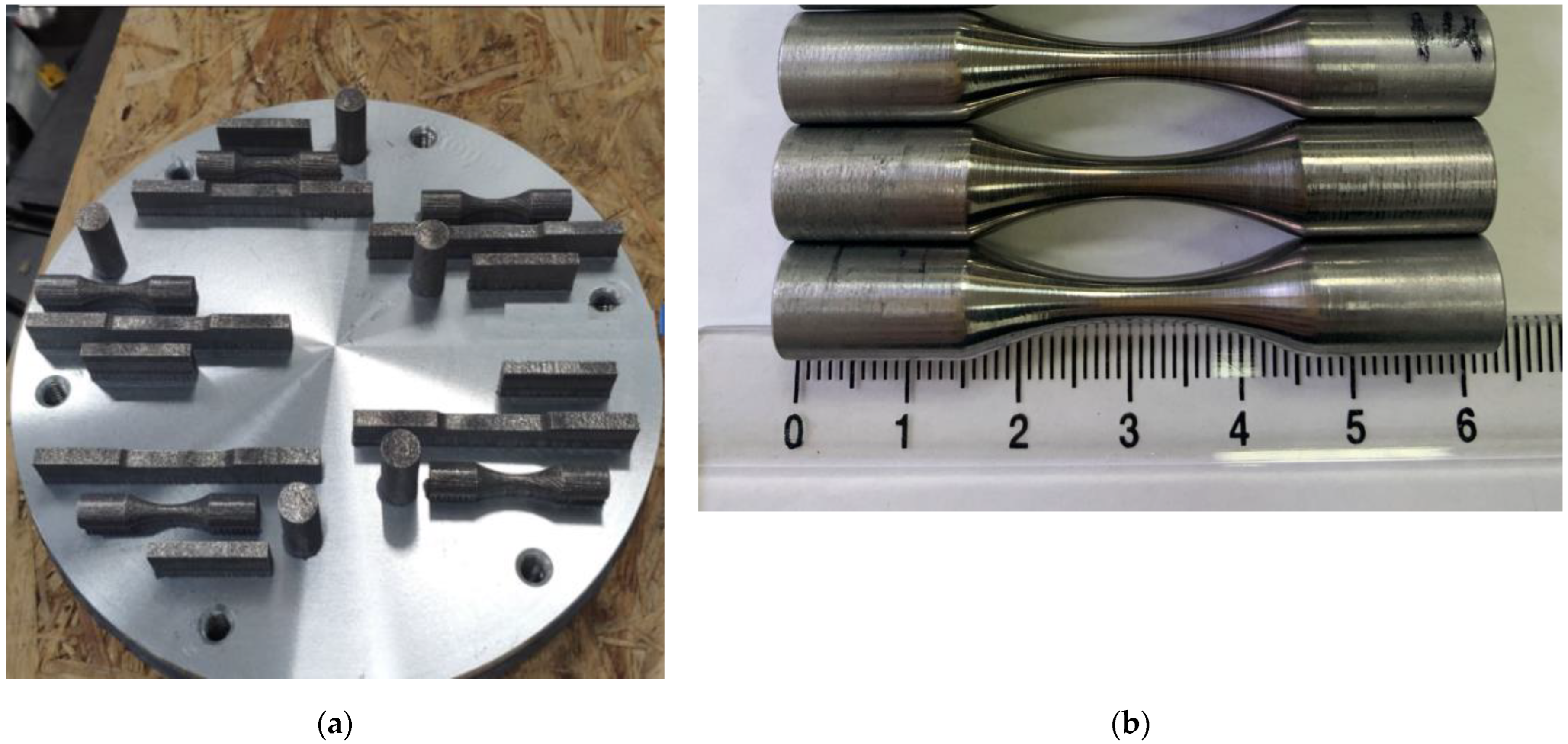
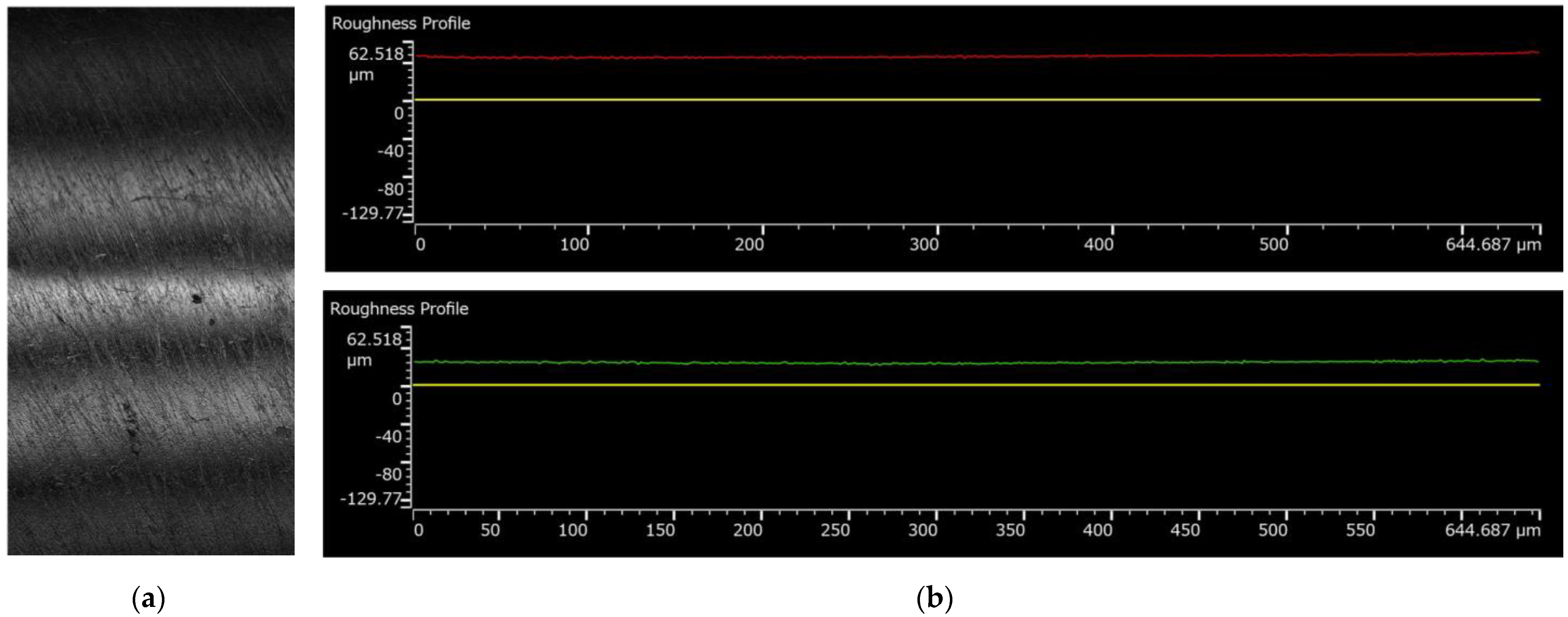
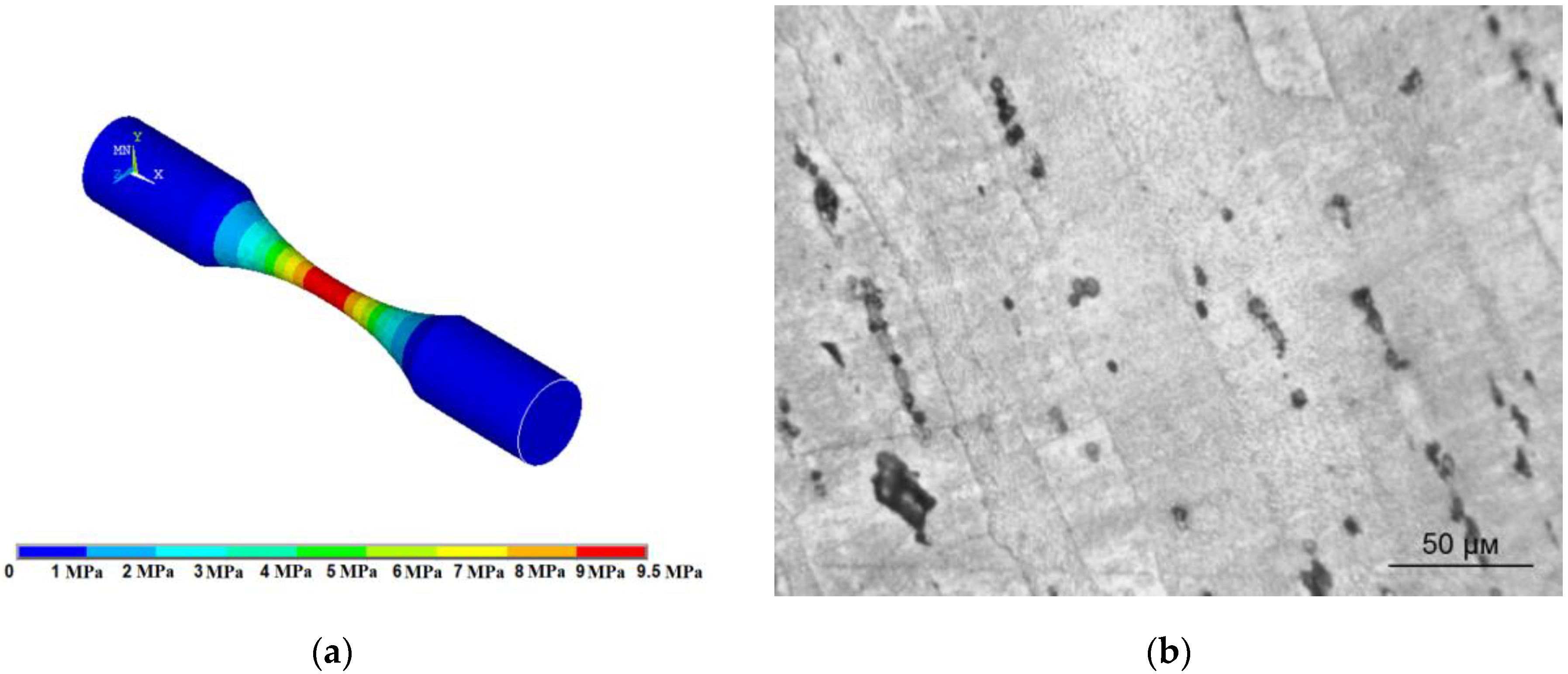
2. Materials and Methods

VHCF tests require an accurate specimen design, especially for materials with a non-homogenous structure at the macroscopic level. SLM produces a layer-by-layer structure due to technological features. The thickness of an individual layer depends on the laser spot parameters and scanning strategy. The next difficulty is correct material filling during the specimen’s production. The presence of voids may affect the mass density of the material. These parameters have an important impact on the dynamic response of the resonant system. That is why, prior to the specimen’s design, a straight cylinder was produced to study the natural frequency of the material. This cylinder was used to determine the mass density of the material and the dynamic Young’s module. The cylindrical bar was investigated on a VHCF testing machine to obtain the exact value of the natural frequency. Based on these premature investigations, the following parameters for the SLM material were obtained: (1) mass density = 2700 kg/m3 and (2) dynamic Young’s modules = 72 GPa. The final shape of the SLM specimens for the VHCF tests made from AlSi10Mg is presented in Figure 1a. A view of the VHCF testing system for axial loading is presented in Figure 1b.
VHCF testing system consists of computer, national instruments external card, Branson generator and piezoelectric converter. The loading train consists of booster and low magnification ultrasonic horn. The fatigue tests are performed under fully reversed loading (R = −1) in the laboratory air environment. The lateral surface of the specimen is permanently cooled by compressed dry air. The pressure of the air flow is controlled by filter at 2 bars. The fatigue tests were carried out under constant amplitude in continuous regime without pauses for cooling. The loading frequency was about 20 kHz. The numerical simulation of the resonant frequency for a whole system with a half of the aluminum specimen (Figure 2a) have shown the frequency drop of about 200 Hz after the final fracture. That is why VHCF testing stop condition was adjust to 150 Hz of natural frequency drop. The result of experimental natural frequency drop for hot-rolled aluminum specimens is shown on the Figure 2b that is in good agreement with numerical simulations. The hot-rolled specimens were investigated on the similar VHCF testing system1 but without the option to adjust the fatigue stop condition. VHCF tests on hot-rolled specimens were performed by using a staircase testing method while SLM specimens were tested at a given stress amplitude to reach VHCF range.
The mechanical properties of the hot-rolled and SLM aluminum alloys are given in the Table 1. The hot-rolled aluminum alloy has a slightly higher ultimate tensile strength compared to SLM material. The mass density is almost the same for both alloys.
The quality of the final SLM product is depending on the quality of initial powder, laser scanning parameters and strategy [16]. The particles of AlSi10Mg aluminum alloy were primary investigated on SEM (Figure 3).
The analysis on the particle shape and size (Figure 3a) have shown a significant difference in radios of an individual particle. The diameter of the spherical particle is varied from 10 to 80 micrometers. The average particle size is about 25 micrometers. The entire observed particle has small (few micrometers) satellites at the sphere surface (Figure 3b). A small companion refers to an attached small particle whose dimensions are much smaller than the main particle, but which disturbs the geometry of the powder and can potentially lead to negative effects during subsequent sintering. The important micro pores present were not observed. Also, some particles have elongated ellipsoid and dumbbell shapes. SLM specimens were built directly in the hourglass specimen shape used for VHCF tests (Figure 4a).
The specimens were built up in the argon environment with low concentration of laboratory air (w < 0.03 %). The samples were fabricated using AlSi10Mg (RUSAL, Russia) powder via AddSol D250 (Addsol, Russia) laser melting system equipped with 400 W optical system. In-plane diameter of the circular built platform was 250 mm. Samples were built by using constant process parameters: laser power 300 W, layer thickness 30 µm, scanning speed 1600 mm/s and spot size 65 µm. The parameters were adjusted based on author’s experience [17,18,19,20]. After manufacturing, the samples together with the platform were placed in the furnace to remove possible temperature residual stresses. After the annealing process, the samples were cut from the platform and milled with subsequent grinding to obtain surface roughness Ra = 0.4 (Figure 5).
The roughness investigations on the produced specimens in different directions (along the specimen axis and across) have shown the following range of Ra = 0.25–0.43. Some scratches and dimples can be observed on the lateral surface of the specimen (Figure 4a). The scratches are due to mechanical polishing.
The calibration of the system was realized by using non-contact optical sensor. The displacements were measured at the bottom of the ultrasonic horn. The stress factor for the aluminum specimens were calculated by using standard harmonic analysis of ANSYS. The result of numerical simulations is presented on the Figure 6a. It was obtained that 1 micrometer of displacements will provide 9.5 MPa. The microstructure of hot-rolled aluminum alloy is presented on the Figure 6b. It is represented by elongated fibers in the direction of bar extrusion. The structure is homogenous except small fraction of additional phases shown in dark color on the Figure 6b. The hot rolled specimens have the same axis with the initial bars.

3. Results and Discussion

The results of VHCF tests on hot-rolled and SLM aluminum alloy are presented on the Figure 7. SN curves for both materials show an important slop without approaching to any horizontal asymptote. The fatigue strength at 107 and 109 is about 40 MPa for hot-rolled alloy and about 30 MPa for SLM one. The dispersion of the results is higher for SLM specimens. The difference in fatigue life at a given stress amplitude reaches more than one orders. In the case of the hot-rolled aluminum alloy the results are close to a tracing line.
The fatigue strength of SLM alloy is about two times lower compared to hot-rolled specimens. The analysis on fracture surfaces has shown the difference in crack initiation and growth mechanisms (Figure 8). The specimens produced by the hot-rolled technology are always showing a single crack initiation while SLM specimens show a multi-crack initiation that is rare under VHCF loadings. The morphology of the fracture surfaces is also quite different. The hot-rolled specimens show three clear stages of crack growth differed by local mechanisms of fracture. SLM specimens show a quasi-homogeneous local fracture mechanism. The detailed analysis for both alloys is given below.

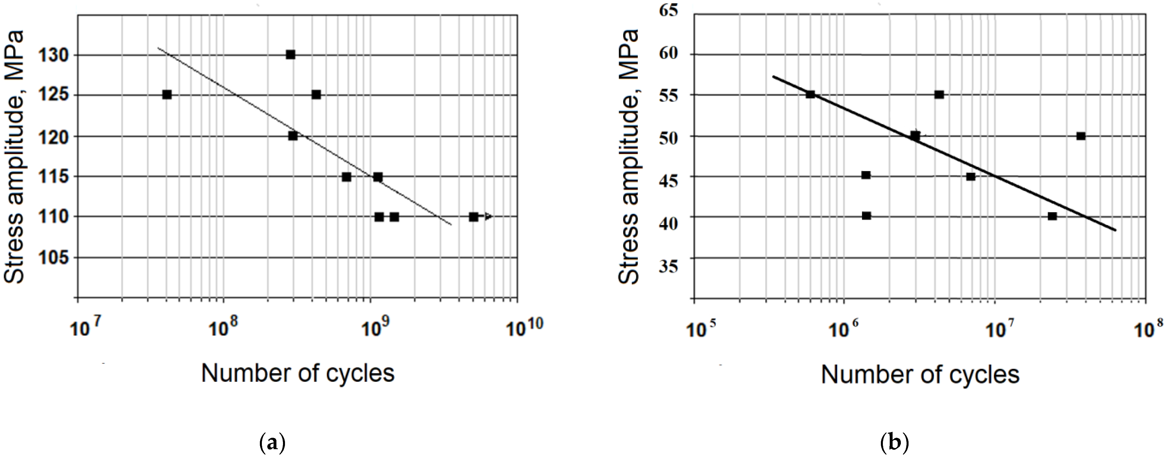
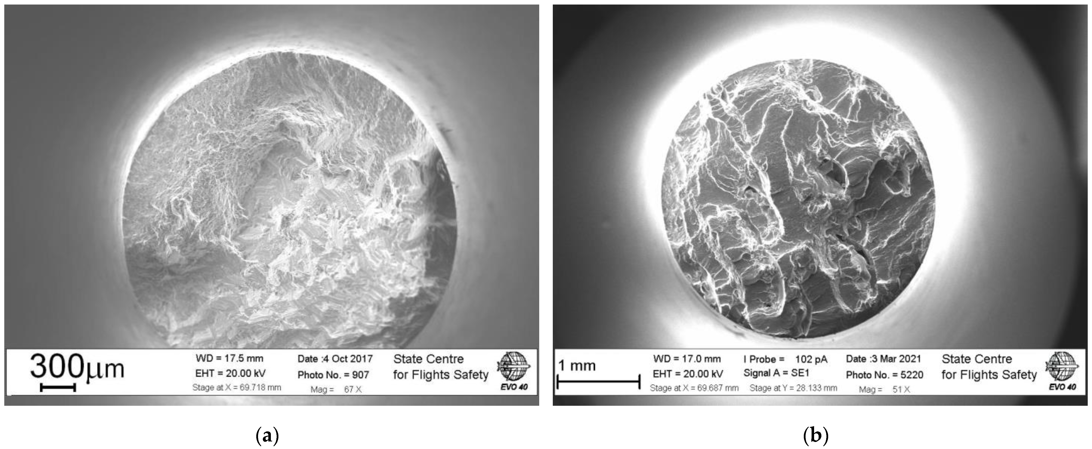
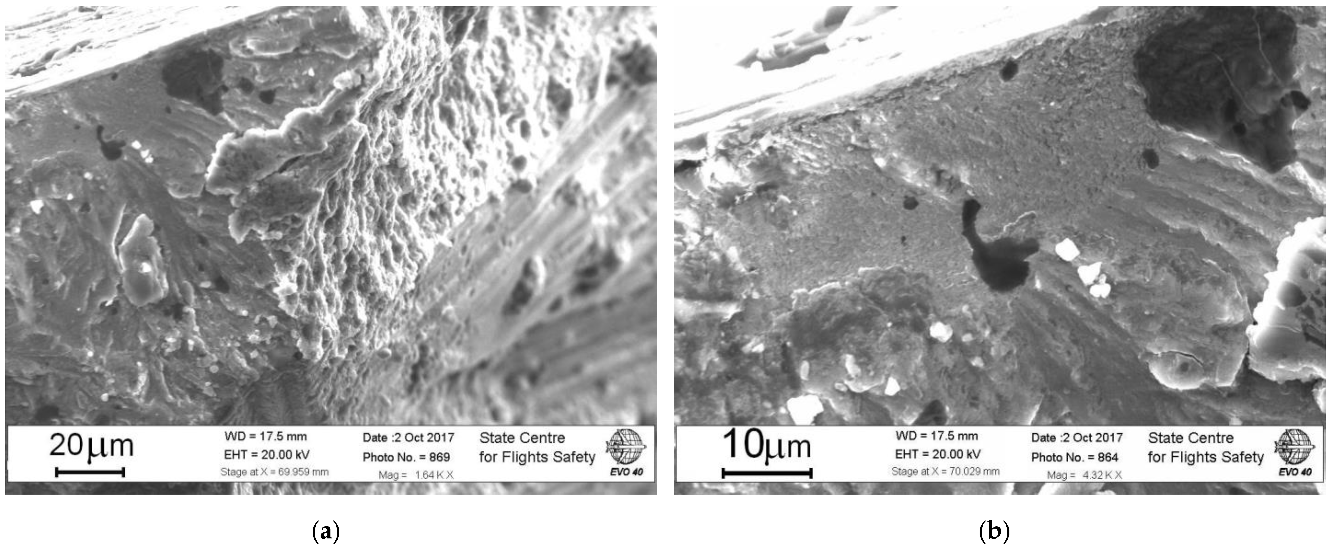
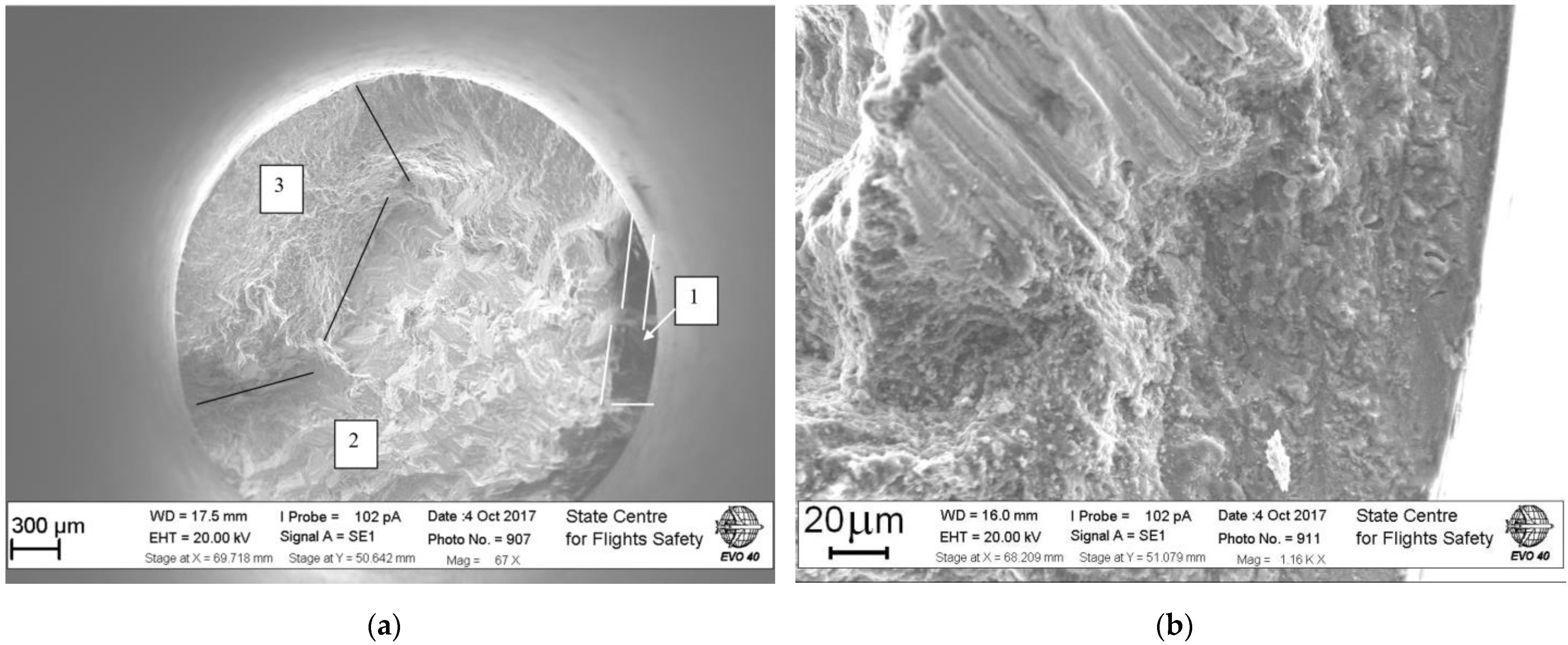
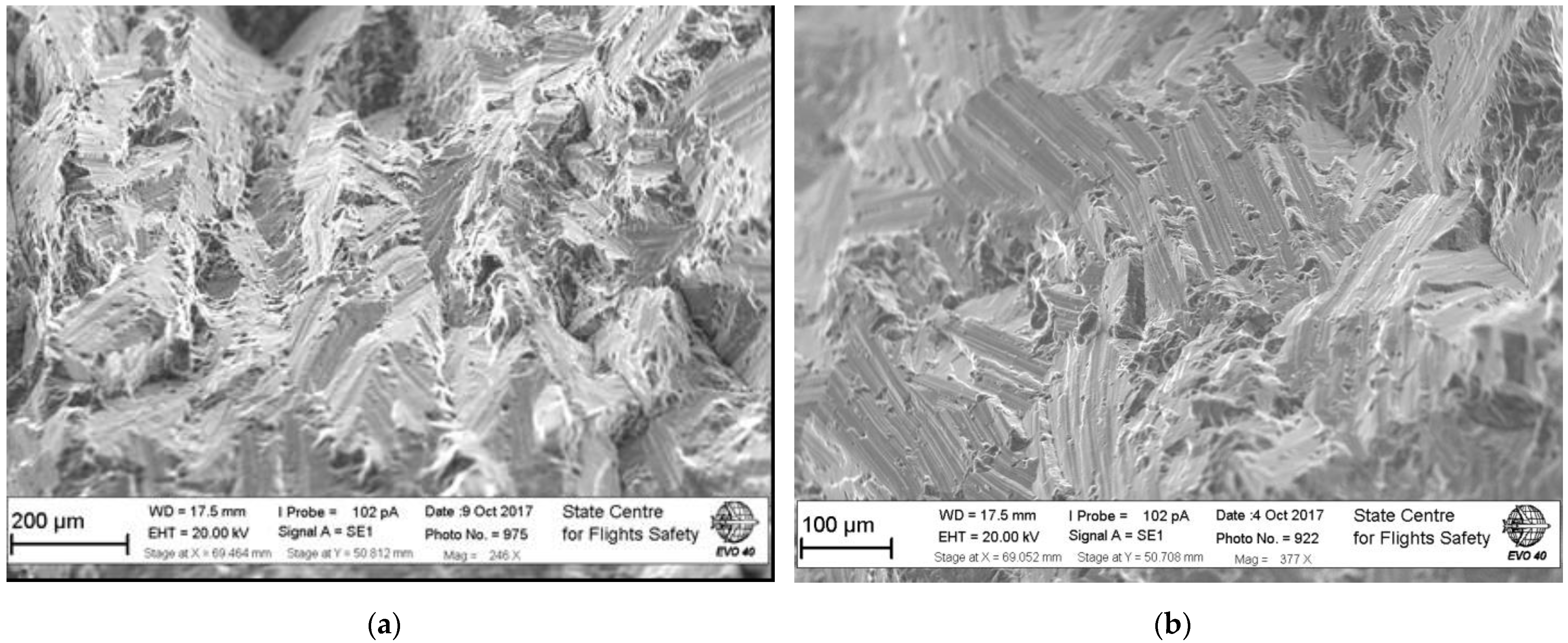
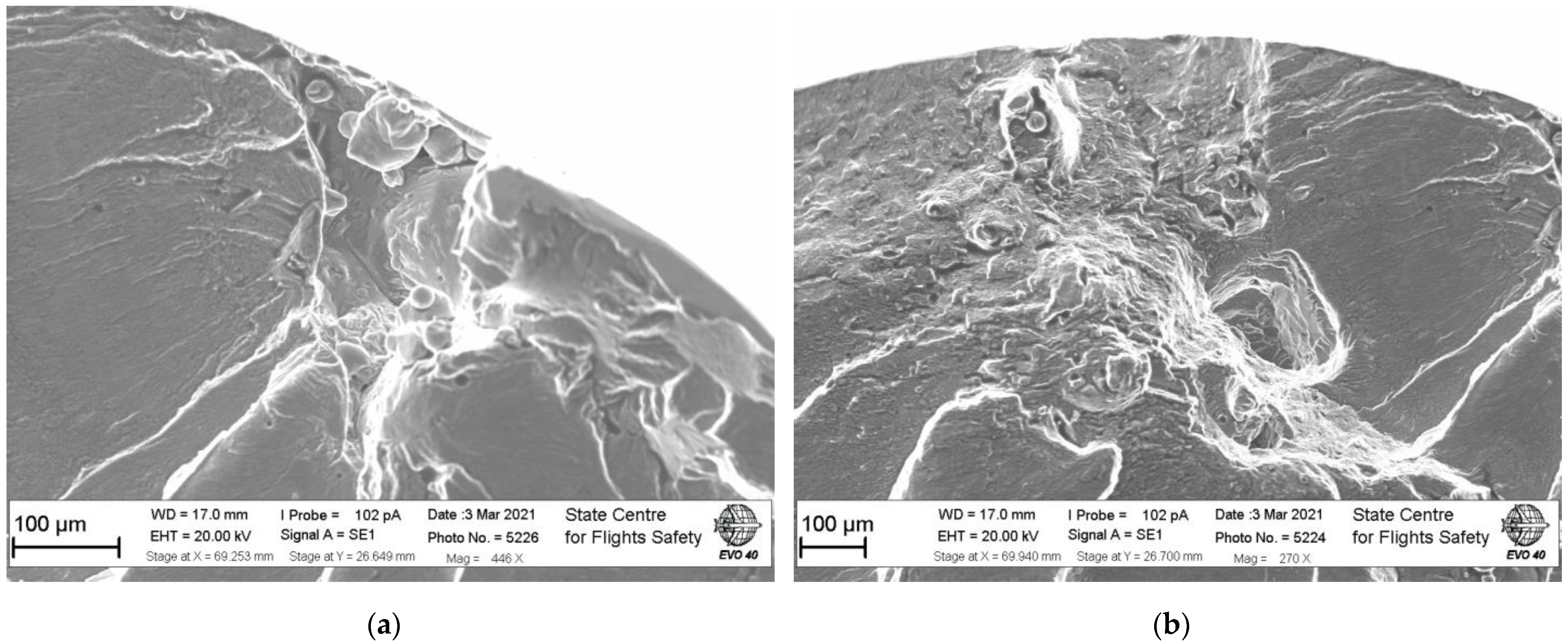
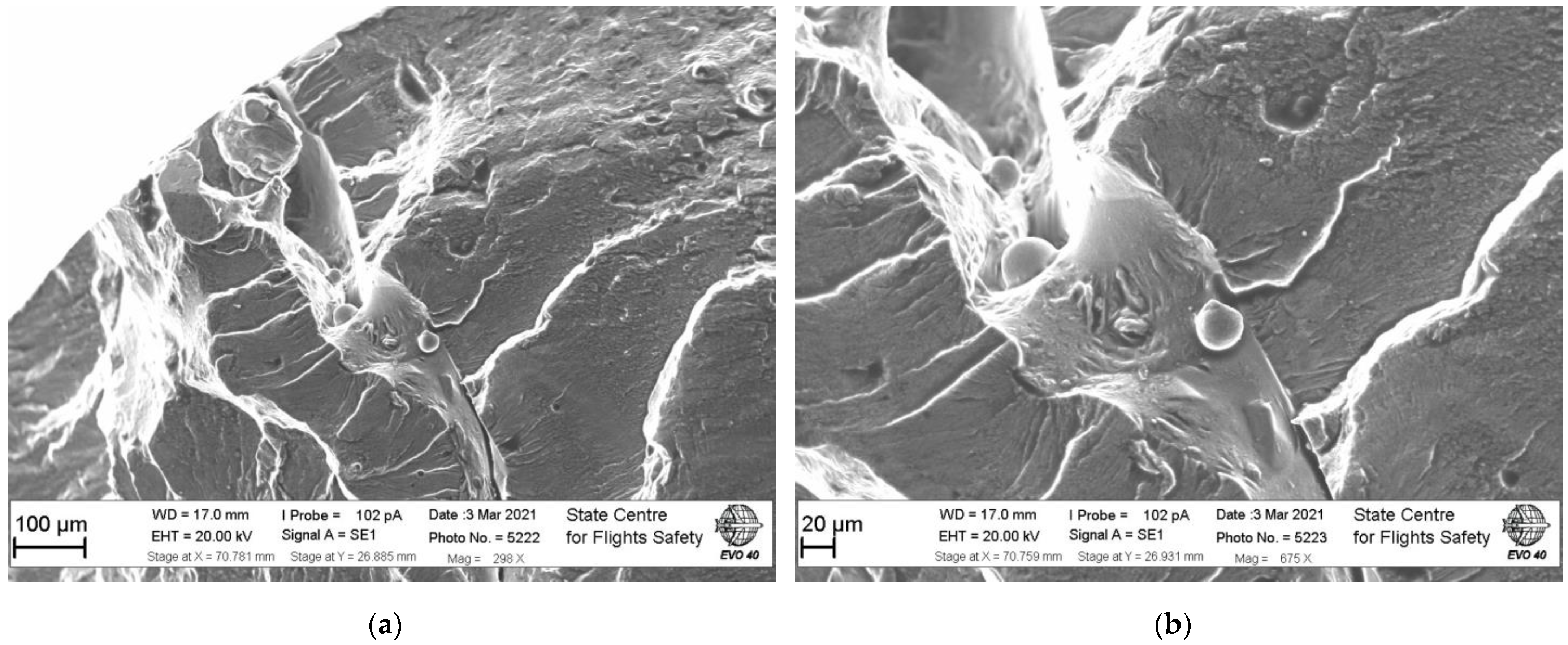
3.1. Crack Initiation and Growth in Hot-Rolled Aluminum Alloy

The analysis on the fracture surfaces of the hot-rolled specimens has shown two types of crack initiations: (1) surface and (2) subsurface crack nucleation. In the case of surface initiation, a semi-ellipsoid micro-crack was observed (Figure 9). The crack size by the specimen surface is about 40 micrometers and growth in depth for 15 micrometers. The plane of the initial crack is perpendicular to applied external load. The morphology of the crack initiation area shows amorphous pattern with bauble-like pattern. This area does not show a clear river like structures showing the crack growth direction. At a certain crack length, a sharp change in crack growth mechanism can be observed (Figure 9b). The fracture patterns turn to be usual for fatigue crack growth in crystallite materials. The initial stage of early crack growth in the plane of maximum normal stress is quite small. At about 80–100 micrometers distance, the radical change in crack growth plane can be observed (Figure 9a). The crack propagation plane has an angle with specimen axis about 45–60 degrees. The mix mode morphology of fracture surface can be observed: some areas show a quasi-brittle pattern while neighboring zones has a ductile fracture with clear dimples (Figure 9a). Further crack growth produces an inclined quasi-brittle fracture pattern that is quite different from initial state. Based on this principal difference two different stages can be introduced on the fracture surface (Figure 10).
The stage II of crack growth produces numerous of quasi brittle platelets. Since specimens were machined so that its axis matches with the bar axis, these elongated platelets are not related to the material structure produced during extrusion.
The analysis on quasi-brittle fracture surface in the zone II show that these elongated platelets are grouped in packages that are randomly orientated one by another (Figure 11). The linear size of these packages is about hounded micrometers.
The neighboring packages do not show and priceable features, such as quasi-ductile zones, in translon from one fractured element to another. The borders are mainly sharp independently of mutual orientation. The quasi-brittle fracture surfaces are rarely covered by individual dimples that are probably related to reinforced phases of aluminum alloy. Sometimes the neighboring packages of elongated quasi-brittle platelets are separated by step-like fracture surfaces. In such cases a ductile fracture mechanism can be observed at the vertical plane of the step. All these features of crack path in zone 2 show a complex character of VHCF fracture of aluminum alloy. It is important to note, that the morphology of fracture surface in zone 2 is not typical for low frequency and in-service failures of aeronautical aluminum alloy. Usually, the aeronautical aluminum alloy is using for skinning the aircrafts and its loading frequency is low enough to produce clear fatigue striations. In the case of high frequency loading the deformation rate is high and does not allow aluminum alloy to realize the potential of plastic deformation. According to the crystallographic structure of the aluminum it has a high potential for plastic deformation. The face-centered cubic structure has 12 sliding systems. The high number of sliding system together with high deformation rate produces the quasi-brittle morphology of fracture surface with arbitrary orientated packages of elongated platelets. The developed morphology of the fracture surface with crack propagation in different planes at different highs produce a complex multiaxial local stress state that leads to mix-mode crack opening. Such crack growth feature produces the neighboring quasi-brittle fracture and sometimes ductile fracture patterns on some individual planes.
Such complex stress state also can produce the local compressive stress acting together with shear crack opening. Such combination of loading parameters can lead to spherical particle formation [16]. Such spherical particles were also observed at different location on the fracture surface of the investigated hot-rolled aluminum alloy.
The final fracture, zone 3 on the Figure 10a, is a typical for many ductile materials. The fracture surface in this zone is covered by dimples. In the case of hot-rolled aluminum alloy the area of final fracture has an important fraction of the whole fracture surface. Depending on the specimen this fraction varies from about 1/8 to 1/6 of the initial cross section of the specimen.

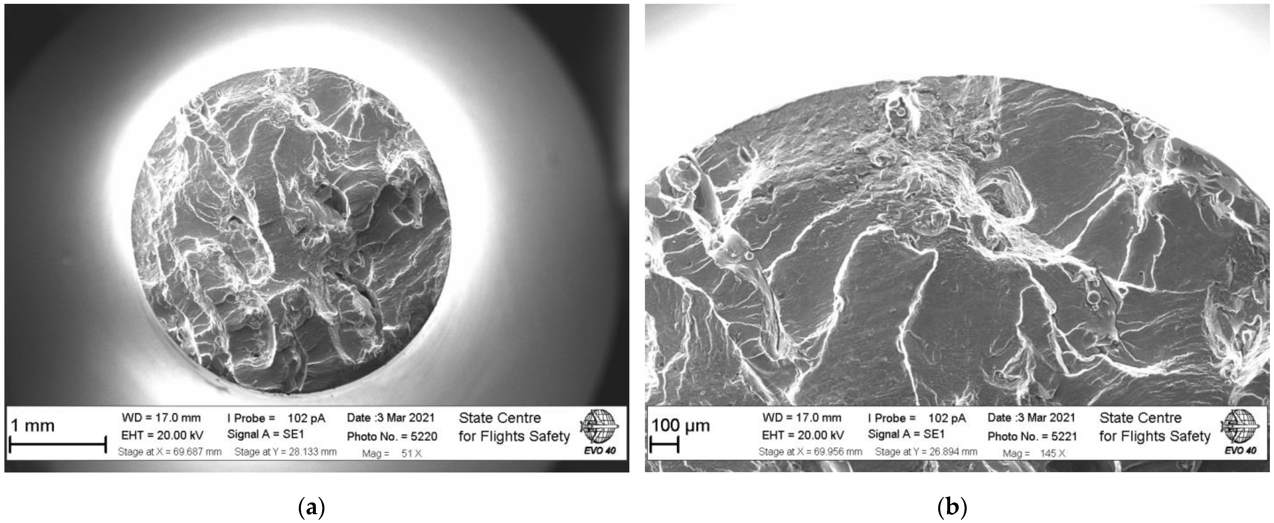
3.2. Crack Initiation and Growth in SLM Aluminum Alloy

The typical fracture surface of SLM specimen is shown on the Figure 12. The fracture surface of this material shows clear traces of the layer-by-layer specimen production. The borders between two neighboring layers have white color on the Figure 12.
The morphology of the fracture surface is quite different from the traditional hot-rolled specimens. The crack is mainly propagating in the plane of maximum normal stress. The inclined zones of crack propagations are very rare and related to fracture of layers bonds. Unlike hot-rolled specimens SLM material produces multi-site crack initiation. It can be seen on the Figure 13b where the semi-ellipsoid crack meets with the crack starting from the boundary of layers. SLM material have many different microstructural defects such as pores, not meld powder, layer boundaries and all these features lead to premature crack initiation.
The semi-ellipsoid crack has initiation from the large pore connected to the specimen surface. Such pores were also observed on the lateral surface of the specimens during the roughness measurements (Figure 5a). Such large defect with linear size of about 100 micrometers (Figure 12a) is an important stress concentration. The deep analysis of the pore surface has shown particles of aluminum powder. Therefore, this region had a bed laser treatment. The same pore was also observed in the bulk of material with an approximately the same linear size. However, under high enough stress amplitude the surface defects dominate over the internal under VHCF loading. However, despite a high stress concentration at the pore the second crack originated from the boundary of the neighboring layers (Figure 14). The precise SEM observation have shown that the boundary of the layers was badly threated, and some powder particles can be observed on the not meld surface. The linear size of such zone is about several hundred micrometers. It seems that during crack opening a part of material stay at opposite fracture surface. Therefore, this large zone was not a pore but the material connection at such location was week. Such state of the material allows the crack initiated at two locations simultaneously and that is why the large not well meld boundary was not the single, dominant crack initiation.
The same particles were observed on the layer’s boundary at different locations. The size of observed particles is varying from 10 to 40 micrometers that is corresponding to the average size of powder particles. Therefore, independently on powder composition the bad meld regions can be observed. This is indicating the laser scanning strategy problem. The build-up of the structures subjected to cyclic loading should be performed with high accuracy of the scanning strategy. The width of the bad meld boundary is varied from 10 to about 80 micrometers that is about the laser spot linear size [21].
The fracture surface does not show any significant changes in crack growth mechanisms that do not allow introducing three stage schemes like it was for hot-rolled specimens. The fracture surface does not show numerous quasi-brittle fracture patterns like it was for hot-rolled specimens. Also, the final fracture fraction is very small compared to the traditional technology specimens. The low roughness of the fracture surfaces and low deviation of crack path from the plane of normal stress indicated a quite high crack growth rate for SLM material under VHCF loading. The large regions of the material were failed in the one single plane (Figure 12 and Figure 13).
The fracture surface of SLM specimen is not symmetric about the diameter of the specimen. The right-hand part (Figure 12a), shows only 2 large bends with internal crack while left hand half contains 4–5 such bends. The fracture surface of SLM specimens presented on the Figure 12a has about 4 bends for the half-diameter length. Thus, the width of each bend is varying from 300 to 1500 micrometers that is much higher than laser spot linear size (65 micrometers). Therefore, the bed melding should be associated mainly with laser scanning strategy and only than with laser beam parameters. The lack of the symmetry between right- and left-hand half of the fracture surface indicates some problems with heat transfer21 from the structure that is design problem. Therefore, VHCF testing method can be very effective in express analysis of SLM parameters and 3D design procedure.

4. Conclusions

VHCF fatigue tests were performed on hot-rolled and SLM aluminum alloy in the laboratory air under axial fully reversed loading R=-1. The results show a significant difference as in fatigue properties as well in crack initiation and growth mechanisms. The hot rolled material shows a single surface or subsurface crack initiation. The source of crack initiation is associated as with pores as well with regular state of material. In the case of surface crack initiation not any defects were found at the crack initiation. The hot rolled fracture surface shows a clear three stage fracture pattern: (1) initiation in the plane of maximum normal stress; (2) crack growth in arbitrary inclined planes with forming quasi-brittle fracture pattern; (3) the final fracture with an important fraction of the initial cross section. In the case of SLM specimens the multiple crack initiation was observed. The crack origination is associated with large pores and bad meld regions of the material. An important role plays the borders of layers. The fracture surface shows several clear bands. These bends are not associated with an individual layer of the powder, but it has a regular nature. These not well meld regions are associated with bad heat transfer and wrong laser scanning strategy that are key parameters for improving fatigue properties of SLM structures.
The observed under VHCF defects in SLM material shows that ultrasonic testing can be effectively used as an express method for control scanning strategy, heat transfer design and laser bean parameters.

Author Contributions

Conceptualization, A.B.; software, A.N.; validation, A.B., A.N. and A.R.; formal analysis, A.N.; investigation A.R.; resources, A.B. and A.N.; data curation, A.R.; writing—original draft preparation, A.B.; writing—review and editing, A.N.; visualization, A.R.; supervision, A.B.; project administration, A.B.; funding acquisition, A.R. All authors have read and agreed to the published version of the manuscript.

Funding

This work was supported by grant MK-398.2022.4 from the President of the Russian Federation.

Institutional Review Board Statement

Not applicable.

Informed Consent Statement

Not applicable.

Data Availability Statement

No new data were created or analyzed in this study. Data sharing is not applicable to this article.

Conflicts of Interest

The authors declare no conflict of interest.

References

  1. Panin, V.E. Synergetic Principles of Physical Mesomechanics. Phys. Mesomech. 2000, 3, 5–34. [Google Scholar] [CrossRef]
  2. Ivanova, V.A. Synergetics. Strength and Fracture of Metal Materials; Nauka: Moscow, Russia, 1992. [Google Scholar]
  3. Shanyavsky, A.A. Scales of Metal Fatigue Cracking. Phys. Mesomech. 2015, 18, 163–173. [Google Scholar] [CrossRef]
  4. Bathias, C.; Paris, P.C. Gigacycle Fatigue in Mechanical Practice; Marcel Dekker: New York, NY, USA, 2005. [Google Scholar]
  5. Shanyavskiy, A.A.; Soldatenkov, A.P. Scales of Metal Fatigue Limit. Phys. Mesomech. 2020, 23, 120–127. [Google Scholar] [CrossRef]
  6. Murakami, Y. Metal Fatigue: Effects of Small Defects and Non-Metallic Inclusions; Elsevier Science Ltd.: London, UK, 2002. [Google Scholar]
  7. Shanyavsky, A.A. Simulation of Fatigue Fracture of Metals; Synergetics in Aviation: Ufa, Russia, 2007. [Google Scholar]
  8. Shanyavskiy, A.A. Self-Organization of Nanostructures in Metals under Ultrahigh Cycle Fatigue. Phys. Mesomech. 2012, 15, 91–105. [Google Scholar]
  9. Shanyavskiy, A. Scale of Metal Fatigue Failures and Mechanisms for Origin of Subsurface Fracture Formation. Sol. State Phen. 2017, 258, 249–254. [Google Scholar] [CrossRef]
  10. Carboni, M.; Annoni, M.; Ferraris, M. Analyses of Premature Failure of Some Aluminum Alloy Sonotrodes for Ultrasonic Welding. Proc. VHCF 2011, 589–594. [Google Scholar]
  11. Shanyavskiy, A. Mechanisms of the 2024-T351 Al-Alloy Fatigue Cracking in Bifurcation Area after Laser Shocks Hardening Procedure. Key Eng. Mater. 2011, 465, 511–514. [Google Scholar] [CrossRef]
  12. Schwerdt, D.; Pyttel, B.; Berger, C. Microstructure Investigations with SEM, EBSD and TEM on Cyclic Stressed and Unstressed Specimens of Two Different Aluminium Wrought Alloys. Proc. VHCF 2011, 207–212. [Google Scholar]
  13. Banhart, J.; Chang, C.S.T.; Liang, Z.; Wanderka, N.; Lay, M.D.H.; Hill, A.J. Natural Aging in Al–Mg–Si Alloys—A Process of Unexpected Complexity. Adv. Eng. Mater. 2010, 12, 559–571. [Google Scholar] [CrossRef]
  14. Mayer, H.; Fitzka, M.; Schuller, R. Ultrasonic Fatigue Testing of 2024-T351 Aluminium Alloy at Different Load Ratios under Constant and Variable Amplitude. Proc. VHCF 2011, 355–360. [Google Scholar]
  15. Kawagoishi, N.; Kariya, K.; Wang, Q.Y.; Maeda, Y.; Goto, M. Effect of Loading Frequency on Fatigue Crack Growth of Age-Hardened Al Alloy. Proc. VHCF 2011, 269–274. [Google Scholar]
  16. Babaytsev, A.V.; Orekhov, A.A.; Rabinskiy, L.N. Properties and microstructure of AlSi10Mg samples obtained by selective laser melting. Nanosci. Techn. 2020, 11, 213–222. [Google Scholar] [CrossRef]
  17. Babaytsev, A.V.; Prokofiev, M.V.; Rabinskiy, L.N. Mechanical properties and microstructure of stainless steel manufactured by selective laser sintering. Int. J. Nanomech. Sci. Techn. 2017, 8, 359–366. [Google Scholar] [CrossRef]
  18. Shaniavski, A.A. Rotational Instability of Mesoscale Deformation and Fracture of Metals in Fatigue Crack Propagation I. Plastic Deformation at the Crack Tip. Phys. Mesomech. 2001, 4, 67–74. [Google Scholar]
  19. Orekhov, A.A.; Rabinskiy, L.N.; Fedotenkov, G.V.; Hein, T.Z. Heating of a half-space by a moving thermal laser pulse source. Lobachevskii J. Math. 2021, 42, 1912–1919. [Google Scholar] [CrossRef]
  20. Kuznetsova, E.L.; Rabinskiy, L.N. Heat transfer in nonlinear anisotropic growing bodies based on analytical solution. Asia Life Sci. 2019, 2, 837–846. [Google Scholar]
  21. Solyaev, Y.; Rabinskiy, L.; Tokmakov, D. Overmelting and closing of thin horizontal channels in AlSi10Mg samples obtained by selective laser melting. Addit. Manuf. 2019, 30, 100847. [Google Scholar] [CrossRef]
Figure 1. The scheme of VHCF specimen made from AlSi10Mg aluminum alloy (a) and VHCF fatigue testing system for axial loading (b).
Inventions 08 00033 g001
Figure 2. The numerical simulation of VHCF system with a half of aluminum specimen (a,b) results of resonant frequency drop for hot-rolled aluminum specimens.
Inventions 08 00033 g002
Figure 3. The powder particles of AlSi10Mg used for VHCF specimens with different magnifications (a,b).
Inventions 08 00033 g003
Figure 4. The platform with SLM specimens before machining (a) and polished specimens (b).
Inventions 08 00033 g004
Figure 5. The quality of SLM specimen surface after polishing (a) scan view and (b) profile measurements.
Inventions 08 00033 g005
Figure 6. The stress distribution in hot-rolled specimens (a) and corresponding microstructure (b).
Inventions 08 00033 g006
Figure 7. The SN-curves for hot-rolled (a) and SLM specimens (b).
Inventions 08 00033 g007
Figure 8. The typical fracture surfaces of hot-rolled (a) and SLM (b) specimens.
Inventions 08 00033 g008
Figure 9. The fracture surface of hot-rolled aluminum alloy specimen with (a) surface and (b) subsurface crack initiation.
Inventions 08 00033 g009
Figure 10. Typical fracture surface of hot-rolled aluminum alloy with clear three stages of crack growth (a) and details of translon from zone I to zone II (b).
Inventions 08 00033 g010
Figure 11. The details of crack growth in hot-rolled specimens VHCF loading. The details of crack growth in hot-rolled specimens with (a) surface and (b) subsurface VHCF loading.
Inventions 08 00033 g011
Figure 12. The typical fracture surface under VHCF loading of SLM aluminum alloy (a) and semi-ellipsoid crack initiated from the large pore (b).
Inventions 08 00033 g012
Figure 13. The fracture surface of SLM specimen with multiple crack initiations. The fracture surface of SLM specimen with multiple crack initiations (a) and semi-ellipsoid crack starting from the boundary of layers (b).
Inventions 08 00033 g013
Figure 14. The details of crack growth in SLM specimens under VHCF loading. General image (a), detailed image (b).
Inventions 08 00033 g014
Table 1. Mechanical properties of D16T and AlSi10Mg aluminum alloys.
MaterialDensity, kg/m3Young’s Module, GPaUTS, MPaElongation, %
Hot-rolled D16T2790743909
SLM AlSi10Mg2700723707
Disclaimer/Publisher’s Note: The statements, opinions and data contained in all publications are solely those of the individual author(s) and contributor(s) and not of MDPI and/or the editor(s). MDPI and/or the editor(s) disclaim responsibility for any injury to people or property resulting from any ideas, methods, instructions or products referred to in the content.

