Article

Mechanical Chaotic Duffing System with Magnetic Springs

1
Computer-Aided Design Department, St. Petersburg Electrotechnical University “LETI”, 5 Professora Popova St., 197376 Saint Petersburg, Russia
2
Youth Research Institute, St. Petersburg Electrotechnical University “LETI”, 5 Professora Popova St., 197376 Saint Petersburg, Russia
3
Department of Biomedical Engineering, Petersburg Electrotechnical University “LETI”, 5 Professora Popova St., 197376 Saint Petersburg, Russia
*
Author to whom correspondence should be addressed.
Inventions 2023, 8(1), 19; https://doi.org/10.3390/inventions8010019
Submission received: 15 November 2022 / Revised: 12 December 2022 / Accepted: 3 January 2023 / Published: 11 January 2023
(This article belongs to the Collection Feature Innovation Papers)

Abstract

:
Mechanical systems with inherent chaotic behavior are of notable practical interest due to their applicability in many fields of technology, from industrial mills and concrete mixers to microscopic micromechanical random bit generators. One of the most generic mathematical models for designing chaotic mechanical systems is the Duffing oscillator, which demonstrates chaotic motion under periodic excitation. The mechanical implementation of Duffing oscillator requires nonlinear springs, which can be implemented using different physical principles. In the current study, we propose the mechanical Duffing oscillator with magnetic springs as a low-wear, robust and easy-to-implement solution. We show by simulation and experimentation that the developed mechanical system performs chaotic oscillations in a wide range of parameters. The proposed design can be revised in a problem-specific manner and achieve many practical applications.

1. Introduction

Chaotic behavior in mechanical systems has been extensively investigated since the 1980s when the theory of chaotic motion became well-established. Examples of early reports on mechanical chaotic systems include works on the parametrically excited pendulum [1], double pendulum [2], a mechanical system with piecewise nonlinearity [3], and many others. However, the studies of that period mostly targeted at not explaining any practically observed phenomena but to verify the universal nature of chaos. Later, it was discovered that chaotic motion can be found in such real engineering systems as airfoils [4,5], suspension systems [6], drilling systems [7,8], etc. In most of these cases, chaos was considered an unintended side effect and an undesirable phenomenon. Meanwhile, in recent years, researchers have focused on the beneficial properties of chaos. An inspiring example of mechanical engineering is a successful and diverse experience of developing electrical chaotic circuits, including GHz frequency devices [9], applied for sensing [10,11,12], secure and ultra-wideband communications [13,14,15], random bit generation [16] and others. One of the promising applications of mechanical chaotic systems is micromachines with chaotic motion. In particular, they are of great interest in advanced medical solutions for diagnostics and targeted drug delivery [17]. Another example includes hardware chaotic generators fabricated as a MEMS device for random number generation [18]. Chaotic MEMS devices can also be used for machine learning based on reservoir computing [19]. Damage detection in the fluid-structural system by mechanical chaos [20], as well as industrial vibrators, e.g., chaotic 4-DOF screen [21], are also promising types of applications. Thus, developing and investigating mechanical chaotic devices is a relevant field in nonlinear science. In addition, the design of advanced control systems requires experimental environments with mechanical nonlinear oscillators.
It is known that a majority of mechanical chaotic systems can be reduced to various modifications of the well-known Duffing oscillator [22]. This canonical oscillator is one of the simplest and thus is very popular for physical implementations. It is described by a second-order non-autonomous differential equation and is usually applied for the simulation of various driven and damped oscillators, e.g., elastic pendulum and nonlinear pendulum with external excitation. The most straightforward realization of the mechanical Duffing oscillator is based on the inverted pendulum, such as the model proposed by Shaw and Rand in 1989 [23]. A practical design based on this idea was independently invented by Berger and Nunes in 1997, who developed a laboratory bench for educational purposes [24]. The main drawback of the inverted pendulum as the generator of mechanical chaotic vibration is the dependency on the gravity field, which prevents it from being used in mechanisms pivoted relative to the horizon during their operation. Another type of implementation includes flexible cantilevers. Two possible macroscopic examples of such a design are described in recent works [25,26], and a microscopic (MEMS) implementation is given in [18].
In this study, we propose and investigate an original implementation of the mechanical Duffing system based on magnetic springs. The dynamics of the system are thoroughly analyzed, and the presence of chaos is confirmed. Magnetic springs used in the proposed design are a known but underestimated solution in engineering, which gained close attention only in recent years. Several works confirm their advantages in practice, namely compact size, absence of failure or wear and noise [27,28,29].
The rest of the paper is organized as follows. In Section 2, general principles of constructing a mechanical Duffing system are given, including the choice of nonlinear springs. In Section 3, the developed physical prototype is described, and the experimental results are reported. Section 4 discusses the results and provides some remarks on possible applications. Section 5 concludes the paper.

2. Materials and Methods

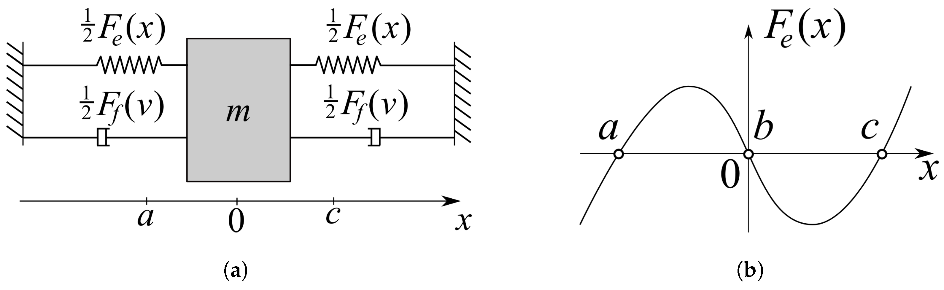
2.1. General Considerations

The forced Duffing oscillator is described by the following equation [22]:
x ¨ + σ x ˙ + α x + β x 3 = γ cos ( ω t ) ,
where the frequency of harmonic excitation is ω and its amplitude is A. Typical parameters needed for the emergence of chaos are α = 1 , β = 5 , σ = 0.02 , γ = 8 and ω = 0.5 .
It can be implemented as a mechanical system using various physical principles, but the overall structure of this system remains the same. If transnational movement is considered, the system is represented as shown in Figure 1a.
The system shown in Figure 1a is a simple mechanical oscillator with damping F f ( v ) . A special shape of the elastic force F e ( x ) is shown in Figure 1b. When there are no external forces, it drives the mass m into two possible stable states: x = a or x = c , so the system is bistable. The point b is an unstable equilibrium, from which the mass escapes under infinitesimal perturbations. When such a bistable system is excited by harmonic oscillations, with the growth of oscillation amplitude or frequency, it experiences a set of period-doubling bifurcations and eventually falls into a chaotic regime.
The equation of motion of such a system is as follows:
m x ¨ + F f ( x ˙ ) + F e ( x ) = γ cos ( ω t ) ,
which, after denoting the velocity as v, reads
x ˙ = v , v ˙ = ( F f ( v ) F e ( x ) + γ cos ( ω t ) ) / m .
The classical choice for the elastic force is a cubic parabola. Together with linear damping, we get a canonical form of the excited Duffing system (1). Nevertheless, two factors restrict the relevance of (1) in describing real mechanical systems and, vice versa, designing practical systems which directly implement this equation. The first one is that precise cubic nonlinearity is impossible in physical systems, and we may deal only with the approximation by a cubic parabola. The second factor restricting the relevance of (1) is that linear (viscous) friction in mechanical systems is usually combined with nonlinear dry friction, which is not taken into account in (1).
Further, we consider both factors and substantiate the proposed design.

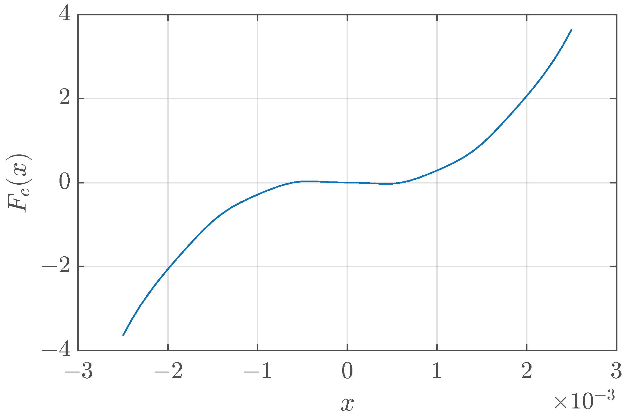
2.2. Choice of Nonlinear Springs

Cubic or nearly cubic nonlinearity can be achieved in many ways. Some special approaches to designing elastic elements with such a nonlinearity can be found in the literature, including conic springs [30] and cam-guided or cam-wrapped springs [31]. However, the truly cubic behavior of F ( x ) is unnecessary. The only requirement is that the elastic force is nonlinear and drives the system into the interval [ a , b ] . An example of a system with backlash from [3] shows that even the use of a piecewise-linear function
F ( x ) = k ( x c ) , x > c , 0 , a x c , k ( x a ) , x < a ,
which provides an infinite number of neutral equilibria inside the interval [ a , b ] , results in an attractor, which is very similar to the attractor of the original Duffing system.
Both considered approaches, the use of nonlinear mechanical springs and the use of backlash, have their drawbacks in real designs. Specially shaped mechanical springs are bulky, difficult to manufacture in a laboratory without special equipment, and costly in mass production. Backlash in a real system will result in a noisy and wear-prone solution.
Therefore, in the current study, we consider magnetic springs as an alternative solution. The magnetic springs possess several notable advantages over mechanical springs: they possess no wear, no noise, no undesirable extra vibrations, and higher power density [28]. Moreover, the interaction between magnets is naturally nonlinear, which simplifies our design, reduces production costs, and makes experimental prototypes easy to construct for scientific and/or educational purposes.
Attractive and repulsive forces between permanent magnets can be calculated using complex FEM analysis, but for our purposes, simpler approximate models are also feasible. A recent investigation by W. Schomburg et al. [32] found the following approximation for the normal force between magnets:
F ( x ) = d e 2 ( x + d e ) 2 F 0 ,
where F 0 is the force when the magnets lean against each other, and d e is the effective distance, at which the force is 1 / 4 of F 0 : F ( d e ) = 1 4 F 0 .
The following approximation for the lateral force between magnets was also proposed:
F ( x ) = L S 2 4 L S 2 4 + x L L 2 4 L S 2 4 L S 2 4 + x + L L 2 4 F m ,
where F m is the maximum force in the lateral direction, L S is a width of a peak at half maximum, and L L is the distance between peaks in positive and negative directions.
Combining normal and lateral types of attracting and repulsive forces through designing various configurations of magnets, it is possible to obtain almost any shape of the force in the mechanical system.
Further, we give an illustration of the described approximations. Figure 2a shows a plot of (3) with the parameters d e = 2 · 10 3 m and F 0 = 4 N. Figure 2b shows a plot of (4) with the parameters L S = 1.5 · 10 3 m, L L = 2 · 10 3 m, F m = 0.5 N. Arrows explain the physical meaning of L S and L L .

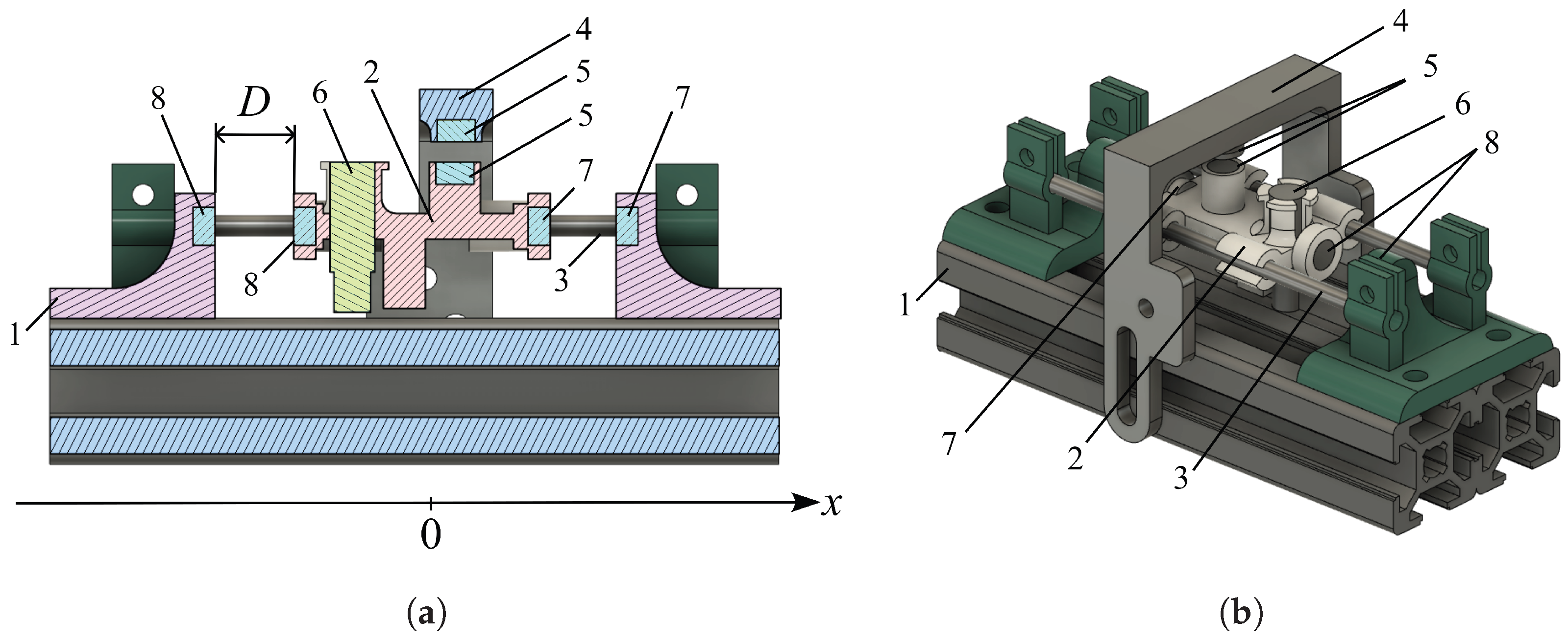
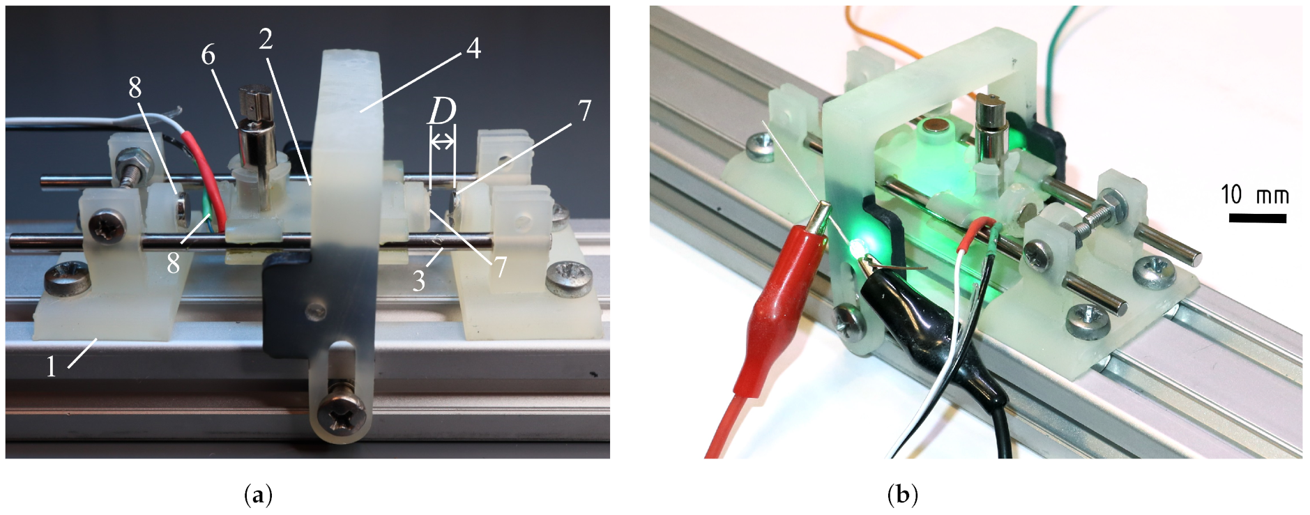
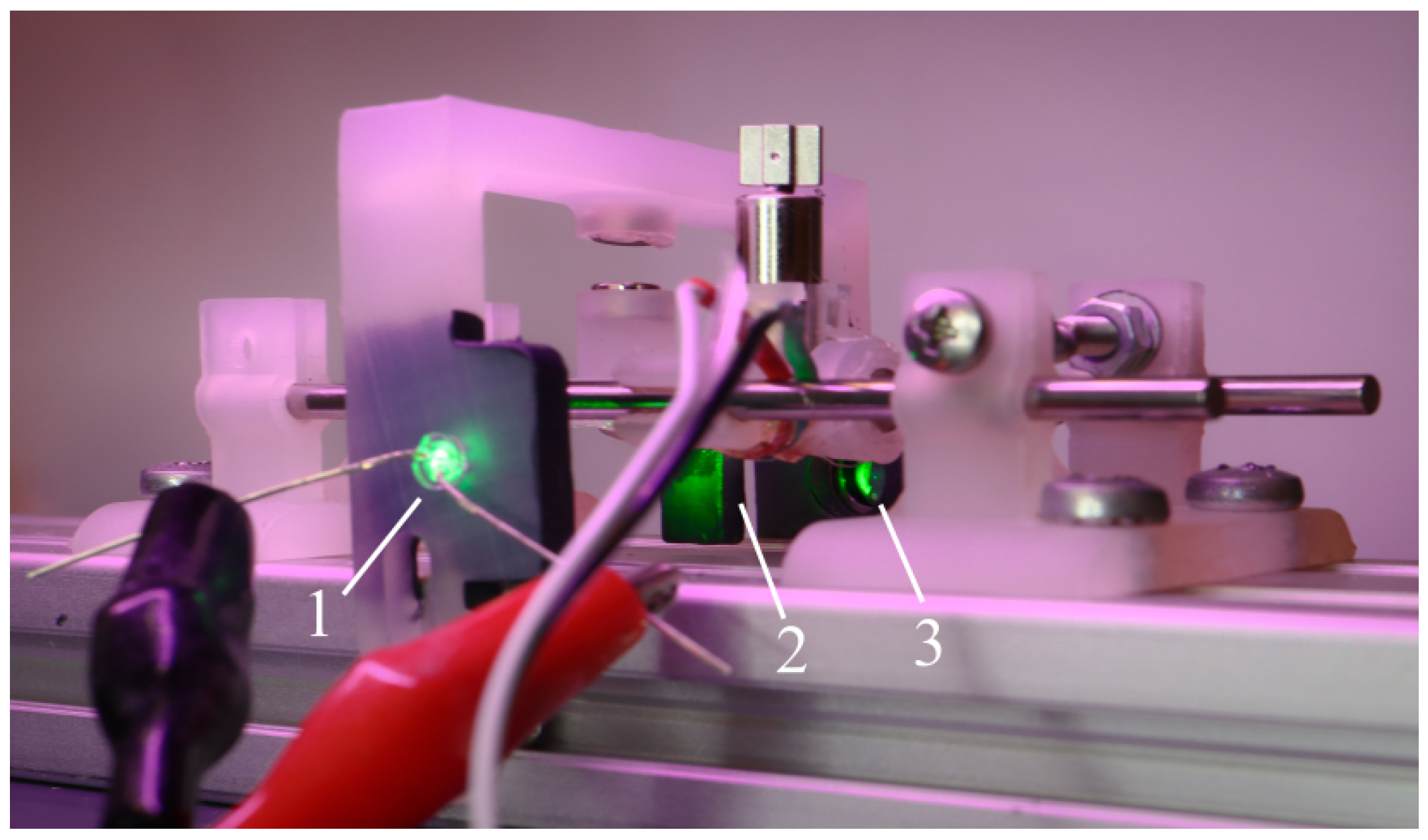
2.3. Design of the Mechanical Oscillator

The idea of the proposed design is to use a conventional DC vibration motor as a source of harmonic excitation. This motor is attached to a carriage with an overall mass of m. To restrict the possible motion of the carriage, it is placed on linear guides, so it can move only along the x axis. An important condition for the oscillator operation is the good sliding of the carriage along the guides. Figure 3a shows a cross-section of the experimental setup, and Figure 3b presents a 3D view of our mechanical design.
Let us consider forces acting on the carriage with attached magnets. Two pairs of repulsive magnets (7) and (8) acting in a normal direction push the carriage from the sides. A pair of repulsive magnets (5) acting in a lateral direction pushes the mass out of the vicinity of the zero position. These three pairs of magnets give the following set of forces:
F 1 ( x ) = d e 2 ( D x + d e ) 2 F 0 , F 2 ( x ) = d e 2 ( D + x + d e ) 2 F 0 , F ( x ) = L S 2 4 L S 2 4 + x L L 2 4 L S 2 4 L S 2 4 + x + L L 2 4 F m , F c ( x ) = F 1 ( x ) F 2 ( x ) F ( x ) ,
where D is the distance between two repulsive magnets (7) and (8) from each side of a carriage when it is in the zero position. Figure 4 shows a plot of a composite function F c from the Formula (5). All parameters are similar to those used for plotting Figure 2.

2.4. Equation of Nonlinear Friction

Having defined equations for the nonlinear magnetic springs, let us consider the issue of the carriage sliding along linear guides. While guides are made of polished steel and the carriage is made of durable photopolymer resin with a rather low friction coefficient, the small mass of the carriage makes the system rather sensitive to dry friction. During operation, the carriage nearly sticks at low velocity, and as it moves faster, the force decreases, so we looked for a model which could reproduce these effects. Multiple dry friction models have been developed; several notable ones are summarized in the review [33]. We have simplified the Karnopp model which represents switching of the dry friction force F f depending on the velocity v:
F f ( v ) = F s sign ( v ) + σ v , | v | v d , F d sign ( v ) + σ v , | v | > v d ,
where F s is a static friction force, F d is a dynamic friction force (it is lower than F s ), σ is a linear friction coefficient, and v d is the velocity tolerance.
The original Karnopp model introduces a special velocity tolerance v d , and when the velocity falls below this speed, it sets to zero. The mass can move again under the action of the external force only if its absolute value exceeds the static friction force F s . Since stiction, or zeroing velocity for a certain time, was not observed in a real-life experiment, our model does no take it into account.

2.5. Equations of a System Excited by a Vibration Motor
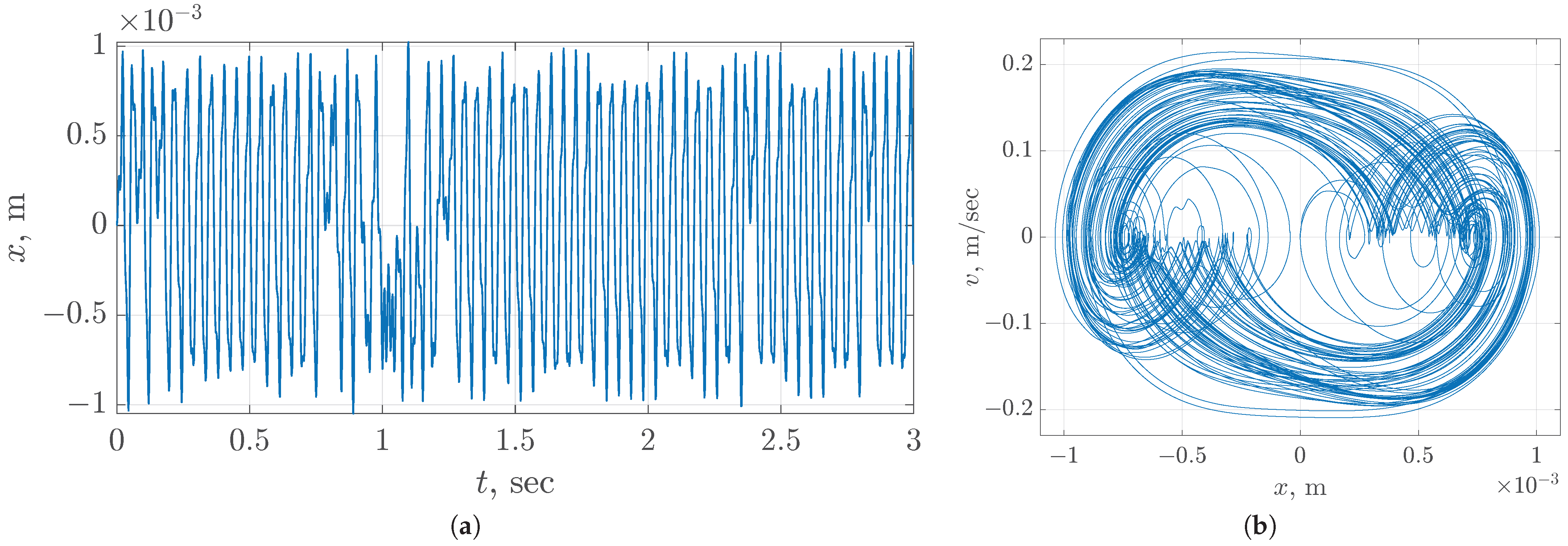
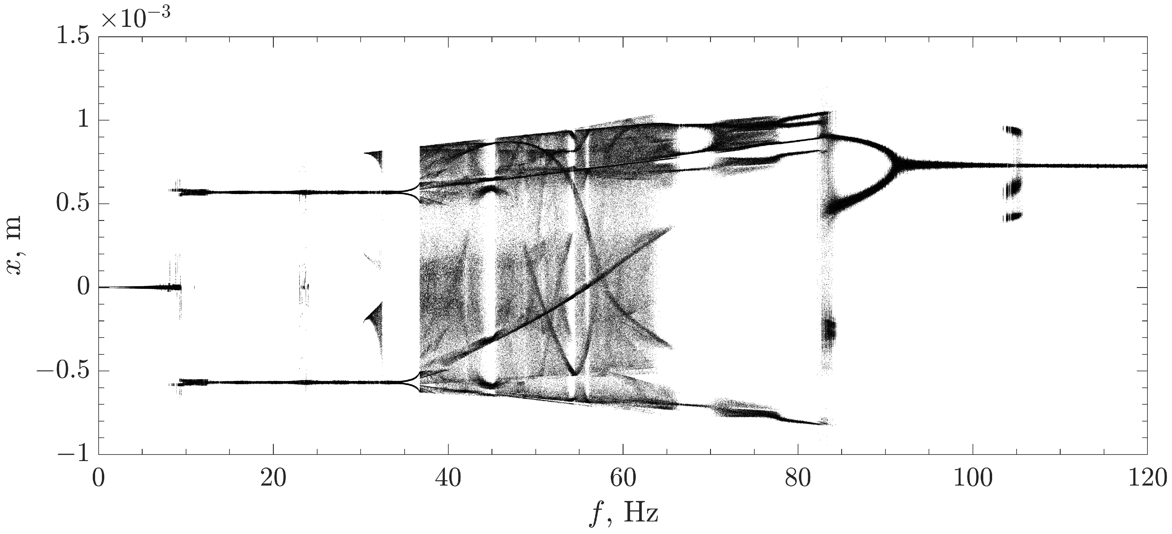
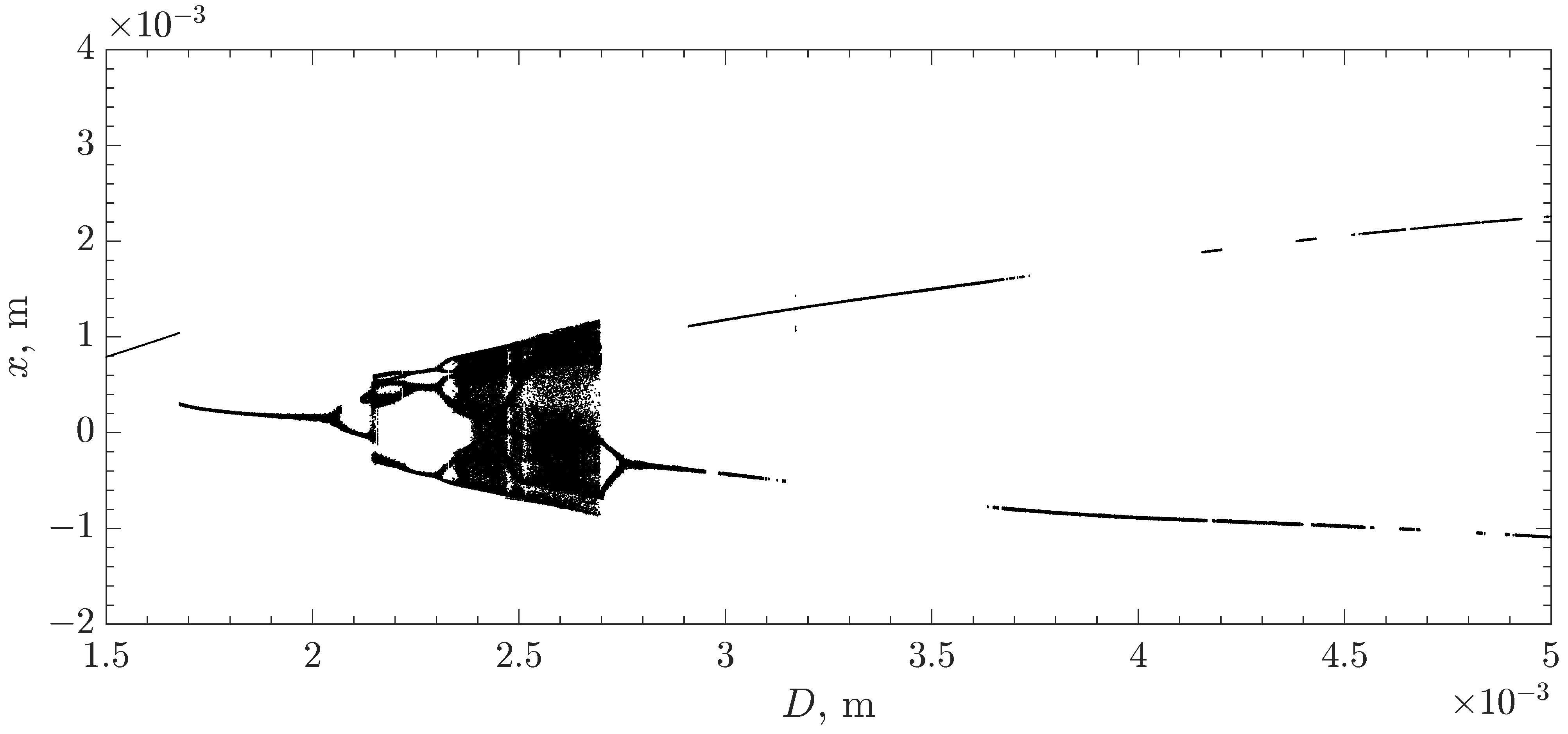
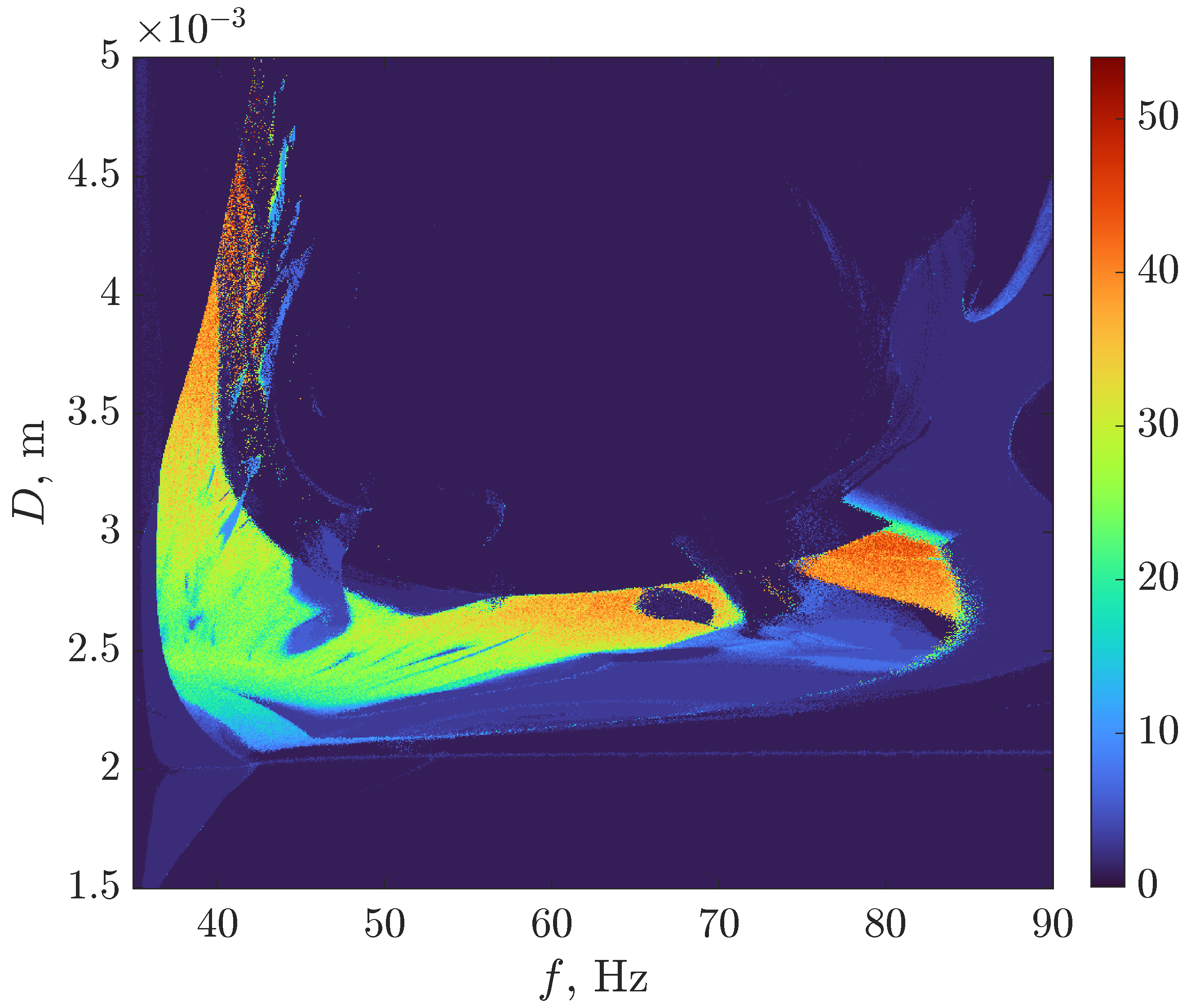
A vibration motor is an electric motor with an asymmetric mass mounted on its axis. This mass transmits a force of inertia, emerging when rotating, through the motor body to an object to which the motor is attached. This force causes the vibration, or mechanical oscillations, of an object. In our case, the object on which the motor is tightly fixed is the carriage. When the acceleration of the carriage is much smaller than the acceleration of the asymmetric mass, we may consider the dynamics of the vibration motor independent from the dynamics of the carriage and assume that the projection of the inertial force of this mass on the x axis is harmonic.
We use a QX-6A-3V motor with a half-cylinder rotating mass with height h and radius R, so its mass can be expressed from its volume and density of steel ρ S as
m r o t = ρ S h π R 2 .
The distance from the center of rotation to the center of mass is d = 4 / ( 3 π ) R , so the amplitude of the force of inertia is expressed as
A = m r o t ω 2 d ,
where ω is an angular frequency of rotation.
The overall equation describing the motion of the proposed mechanical system is
x ˙ = v , v ˙ = ( F f ( v ) F c ( x ) + A cos ( ω t ) ) / m ,
where the friction force F f ( v ) is defined by Equation (6), magnetic spring force F c ( x ) is defined by Equation (5), and the amplitude of the excitation force A is defined by Equation (7).

3. Results

3.1. Numerical Analysis

Using numerical simulation, we investigated the model (8) by substituting measured and approximated physical parameters of the experimental setup. For convenience, all parameters are given in Table 1.
In all numerical simulations, we use the 8th-order Dormand–Prince integration method with integration step size h = 10 4 . The initial conditions of all variables were zeroes. The time series and phase portrait of the proposed mechanical chaotic oscillator obtained by numerical simulation are shown in Figure 5.
Let us investigate the model by changing the frequency of vibration f and the initial distance between side magnets D. Bifurcation diagrams while varying parameters f and D are shown in Figure 6 and Figure 7, respectively. Note that chaotic motion presents only in a certain frequency band. This phenomenon is common for physical implementations of the Duffing oscillator, e.g., compare the obtained results with the results obtained for the electrical model in [12].
We also provide a two-dimensional bifurcation diagram about parameters f and D, see Figure 8. The pseudoimage of a two-dimensional bifurcation diagram is obtained using the kernel density estimation (KDE) algorithm [34] applied to each point of the diagram.
Red regions of the two-dimensional bifurcation diagram correspond to parameter values where oscillations are more irregular. Blue regions are the regions of periodic oscillations.

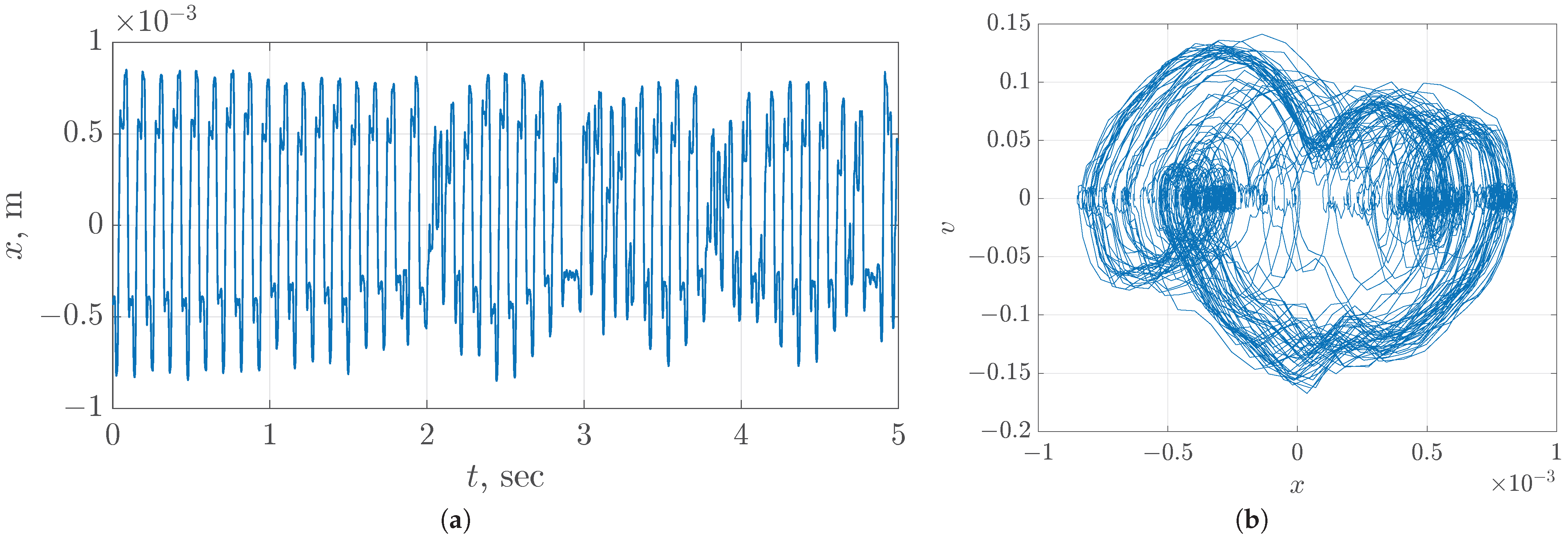
3.2. Experimental Results

The experimental setup was created using 3D photopolymer printing and parts of the industrial CNC machines. The design contains only four specific 3D-printed details: two side frames, a carriage, and a top frame. Magnets, screws, a DC vibration motor, and an aluminum profile were on-the-shelf products. Linear guides are identical to those used in DVD drives. Figure 9 presents the physical prototype. The numbers in the annotation correspond to the numbers in Figure 3a. One can see the features of the implemented design in detail: the repulsive magnets, vibration motor (DC motor with an unbalanced rotor), displacement measurement optical system and other features.
To measure the displacement x of the carriage, the optical sensor was utilized. The movement measurement system consists of a green LED, a shutter, a photodiode, an amplifier, and an oscilloscope. Plastic parts used in optical measurements, including the shutter, were painted in black. When the carriage moves, the shutter partially closes the light stream from the LED to the photodiode and the voltage at the amplifier changes, see Figure 10.
To convert the photodiode voltage to a displacement, we performed a set of measurements using the digital oscilloscope with a software DC meter, and the dial test indicator (Figure 11a). Obtained voltage–distance pairs were approximated by a linear function, see Figure 11b, with resulting RMS error ε = 2.917 · 10 5 m.
The value of v was reconstructed from x computationally by numerical differentiation. Figure 12 demonstrates time domain and phase portrait obtained at the following values of parameters: initial distance D = 4 mm, excitation frequency f = 26.4 Hz.

4. Discussion

4.1. Correspondence between Model and Experiment

One can visually compare the phase space shown in Figure 12 and the numerically obtained attractor in Figure 5, and conclude that they are generally similar. The more complex shape of the experimental attractor is conditioned by the inaccuracy of the model (8). The exact identification of the considered mechanical system is a very difficult problem. There are multiple sources of discrepancy between the simulated and mechanical system, including friction, lack of rigidity in real mechanics, electromagnetic interference in data acquisition channels, etc. Standard least-square identification procedures work well when all terms are of almost similar scale, but in the considered system, one of the most important terms—namely, friction—is rather small. In this case, even a moderate level of noise in the data prevents one from accurately identifying the friction governing equation. This makes the approximate physically motivated model presented in the current study the best possible choice. Complicated denoising and optimization techniques could help to solve this issue, but they are out of scope in the current study. In addition, the lack of rigidity in the real mechanical system would always result in increasing the dimension of the model. Data-based model identification techniques could also help in deriving a more accurate model, but we tried to avoid this because the model could become too complicated and even over-fitted. Another additional source of error is the inaccuracy of measurements, but our numerical investigation showed that sub-millimeter instrumental error in all coefficients would not result in a more precise shape of the attractor.
Moreover, one of the important factors which was ignored but plays a notable role in a physical experiment, is the effect of carriage movement on the vibration motor frequency. The set of parameters D and f used to obtain the experimental attractor presented in Figure 12 does not lead to chaos according to the 2D bifurcation diagram in Figure 8. However, this does not mean that the numerical analysis of this chaotic system is of no importance. It reveals that chaos in the designed system is rather robust, which is verified by the size of chaotic regions. Nevertheless, the disruption between the experimental setup and the model is yet another confirmation that real-world systems often behave in a more complicated way than the mathematical models they are supposed to correspond to, which is consistent with numerous observations in chaotic electronic circuits [35,36,37].

4.2. Possible Applications and Improvements

The results of this study may find applications in vibration systems where it is necessary to convert the narrow-band mechanical vibrations of the driving motor into a wide-band vibration inherent to chaotic oscillators, ensuring the reliability of the design and its simplicity: the absence of gears, electric magnets and complicated control electronics. Examples of such systems include shakers, vibrating screens and vibrating robots.
As for the possible improvement of our design, we may use a linear resonant actuator instead of a vibration motor. It also seems interesting to investigate the magnetic springs in a system with not translational, but rotational motion. We assume it would allow a significant decrease in the mass and size of the chaotic vibrator since the torsional friction may be almost fully eliminated by rotary bearings.

5. Conclusions

In this paper, a novel implementation of the chaotic Duffing oscillator is proposed as a simple mechanical system with a translational movement. The key feature of our design is the use of magnetic springs, by which a smooth nonlinear force is introduced. A standard micro-vibration motor is used as a drive for the developed oscillator. A mathematical model taking into account the nonlinear dry friction between the carriage and guides and the nonlinear magnetic interaction was developed. Chaotic regimes of the proposed system were investigated using phase plane analysis and multidimensional bifurcation analysis. An experimental prototype was created, and the similarity of attractors between the mathematical model and the mechanical prototype was observed. We may conclude that the concept of the experimental stand was explicitly proven.
The directions of further work would include, but are not limited to, the synchronization of coupled mechanical chaotic oscillators, developing a control system for governing oscillation mode in mechanical chaotic oscillators, and investigating the possibility of constructing physical pseudo-random number generators based on mechanical chaos. Practical applications, especially in the field of micro-robotics, are also of high interest.

Author Contributions

Conceptualization, A.K. and D.B.; methodology, resources A.K. and Y.B.; software, A.K., V.R. and T.K; validation and formal analysis, A.K., and D.B.; investigation, A.D., A.K., T.K., V.R.; design and manufacturing the experimental setup, A.D. and Y.B.; data curation, V.R., T.K. and Y.B.; writing—original draft preparation, A.K., V.R. and T.K.; writing—review and editing, D.B.; visualization, A.D., T.K. and V.R.; supervision, project administration, funding acquisition, D.B. All authors have read and agreed to the published version of the manuscript.

Funding

This study is supported by Russian Science Foundation, project 22-19-00573.

Data Availability Statement

Not applicable.

Conflicts of Interest

The authors declare no conflict of interest. The funders had no role in the design of the study; in the collection, analyses, or interpretation of data; in the writing of the manuscript; or in the decision to publish the results.

References

  1. d’Humieres, D.; Beasley, M.; Huberman, B.; Libchaber, A. Chaotic states and routes to chaos in the forced pendulum. Phys. Rev. A 1982, 26, 3483. [Google Scholar] [CrossRef]
  2. Richter, P.H.; Scholz, H.J. Chaos in classical mechanics: The double pendulum. In Stochastic Phenomena and Chaotic Behaviour in Complex Systems; Springer: Berlin/Heidelberg, Germany, 1984; pp. 86–97. [Google Scholar]
  3. Lin, R.; Ewins, D. Chaotic vibration of mechanical systems with backlash. Mech. Syst. Signal Process. 1993, 7, 257–272. [Google Scholar] [CrossRef]
  4. Li, D.; Xiang, J. Chaotic motions of an airfoil with cubic nonlinearity in subsonic flow. J. Aircr. 2008, 45, 1457–1460. [Google Scholar]
  5. Abdelkefi, A.; Vasconcellos, R.; Marques, F.D.; Hajj, M.R. Bifurcation analysis of an aeroelastic system with concentrated nonlinearities. Nonlinear Dyn. 2012, 69, 57–70. [Google Scholar] [CrossRef]
  6. Golouje, Y.N.; Abtahi, S.M. Chaotic dynamics of the vertical model in vehicles and chaos control of active suspension system via the fuzzy fast terminal sliding mode control. J. Mech. Sci. Technol. 2021, 35, 31–43. [Google Scholar] [CrossRef]
  7. Xue, Q.; Leung, H.; Wang, R.; Liu, B.; Huang, L.; Guo, S. The chaotic dynamics of drilling. Nonlinear Dyn. 2016, 83, 2003–2018. [Google Scholar] [CrossRef]
  8. Abro, K.A.; Atangana, A. Numerical and mathematical analysis of induction motor by means of AB–fractal–fractional differentiation actuated by drilling system. Numer. Methods Part. Differ. Equ. 2022, 38, 293–307. [Google Scholar] [CrossRef]
  9. Demirkol, A.S.; Tavas, V.; Ozoguz, S.; Toker, A. High frequency chaos oscillators with applications. In Proceedings of the 2007 18th European Conference on Circuit Theory and Design, Sevilla, Spain, 27–30 August 2007; pp. 1026–1029. [Google Scholar]
  10. Karimov, T.; Druzhina, O.; Karimov, A.; Tutueva, A.; Ostrovskii, V.; Rybin, V.; Butusov, D. Single-coil metal detector based on spiking chaotic oscillator. Nonlinear Dyn. 2021, 107, 1295–1312. [Google Scholar] [CrossRef]
  11. Minati, L.; Tokgöz, K.K.; Ito, H. Distributed sensing via the ensemble spectra of uncoupled electronic chaotic oscillators. Chaos Solitons Fractals 2022, 155, 111749. [Google Scholar] [CrossRef]
  12. Karimov, T.; Druzhina, O.; Vatnik, V.; Ivanova, E.; Kulagin, M.; Ponomareva, V.; Voroshilova, A.; Rybin, V. Sensitivity Optimization and Experimental Study of the Long-Range Metal Detector Based on Chaotic Duffing Oscillator. Sensors 2022, 22, 5212. [Google Scholar] [CrossRef]
  13. Sahin, M.; Cam Taskiran, Z.; Guler, H.; Hamamci, S. Simulation and implementation of memristive chaotic system and its application for communication systems. Sens. Actuators A Phys. 2019, 290, 107–118. [Google Scholar] [CrossRef]
  14. Dmitriev, A.; Efremova, E.; Itskov, V.; Petrosyan, M.; Ryzhov, A.; Turkanov, I. Direct Chaotic Ultra-Wideband Wireless Communications in the Very High Frequency and Ultra High Frequency Radio Bands. J. Commun. Technol. Electron. 2022, 67, 1013–1021. [Google Scholar] [CrossRef]
  15. Fellah, R.; Azzaz, M.S.; Tanougast, C.; Kaibou, R. Design of a simple and low cost chaotic signal generation circuit for UWB applications. Eur. Phys. J. Spec. Top. 2021, 230, 3439–3447. [Google Scholar] [CrossRef]
  16. Addabbo, T.; Fort, A.; Mugnaini, M.; Petra, N.; Takaloo, H.; Vignoli, V. Self-tunable chaotic true random bit generator in current-mode CMOS circuit with nonlinear distortion analysis. Int. J. Circuit Theory Appl. 2019, 47, 1877–1892. [Google Scholar] [CrossRef]
  17. Zhang, H.; Li, X.; Chuai, R.; Zhang, Y. Chaotic Micromixer Based on 3D Horseshoe Transformation. Micromachines 2019, 10, 398. [Google Scholar] [CrossRef] [Green Version]
  18. Barceló, J.; de Paúl, I.; Bota, S.; Segura, J.; Verd, J. Chaotic signal generation in the MHz range with a monolithic CMOS-MEMS microbeam resonator. In Proceedings of the 2019 IEEE 32nd International Conference on Micro Electro Mechanical Systems (MEMS), Seoul, Republic of Korea, 27–31 January 2019; pp. 1037–1040. [Google Scholar]
  19. Zheng, T.; Yang, W.; Sun, J.; Xiong, X.; Li, Z.; Zou, X. Parameters optimization method for the time-delayed reservoir computing with a nonlinear duffing mechanical oscillator. Sci. Rep. 2021, 11, 997. [Google Scholar] [CrossRef]
  20. Epureanu, B.I. Chaotic Vibration-Based Damage Detection in Fluid-Structural Systems; Springer: Dordrecht, The Netherlands, 2003; pp. 43–58. [Google Scholar]
  21. Zhang, M.; Wang, C.; Yan, C.; Li, H. Design and Dynamic Analysis of a Four-Degree-of-Freedom Chaotic Vibrating Screen. Shock Vib. 2021, 2021, 8830428. [Google Scholar] [CrossRef]
  22. Duffing, G. Erzwungene Schwingungen Bei Veränderlicher Eigenfrequenz und Ihre Technische Bedeutung; Number 41-42; Vieweg: Braunschweig, Germany, 1918. [Google Scholar]
  23. Shaw, S.W.; Rand, R.H. The transition to chaos in a simple mechanical system. Int. J. Non-Linear Mech. 1989, 24, 41–56. [Google Scholar] [CrossRef]
  24. Berger, J.; Nunes, G., Jr. A mechanical Duffing oscillator for the undergraduate laboratory. Am. J. Phys. 1997, 65, 841–846. [Google Scholar] [CrossRef]
  25. Margielewicz, J.; Gąska, D.; Litak, G.; Wolszczak, P.; Zhou, S. Energy Harvesting in a System with a Two-Stage Flexible Cantilever Beam. Sensors 2022, 22, 7399. [Google Scholar] [CrossRef]
  26. Brunetti, M.; Mitura, A.; Romeo, F.; Warminski, J. Nonlinear dynamics of bistable composite cantilever shells: An experimental and modelling study. J. Sound Vib. 2022, 526, 116779. [Google Scholar] [CrossRef]
  27. Zheng, Y.; Li, Q.; Yan, B.; Luo, Y.; Zhang, X. A Stewart isolator with high-static-low-dynamic stiffness struts based on negative stiffness magnetic springs. J. Sound Vib. 2018, 422, 390–408. [Google Scholar] [CrossRef]
  28. Mrak, B.; Lenaerts, B.; Driesen, W.; Desmet, W. Optimal magnetic spring for compliant actuation—Validated torque density benchmark. Actuators 2019, 8, 18. [Google Scholar] [CrossRef] [Green Version]
  29. Poltschak, F.; Ebetshuber, P. Design of integrated magnetic springs for linear oscillatory actuators. IEEE Trans. Ind. Appl. 2018, 54, 2185–2192. [Google Scholar] [CrossRef]
  30. Qiu, D.; Seguy, S.; Paredes, M. A novel design of cubic stiffness for a Nonlinear Energy Sink (NES) based on conical spring. In Advances on Mechanics, Design Engineering and Manufacturing; Springer: Berlin/Heidelberg, Germany, 2017; pp. 565–573. [Google Scholar]
  31. Rivlin, B.; Elata, D. Design of nonlinear springs for attaining a linear response in gap-closing electrostatic actuators. Int. J. Solids Struct. 2012, 49, 3816–3822. [Google Scholar] [CrossRef] [Green Version]
  32. Schomburg, W.K.; Reinertz, O.; Sackmann, J.; Schmitz, K. Equations for the approximate calculation of forces between cuboid magnets. J. Magn. Magn. Mater. 2020, 506, 166694. [Google Scholar] [CrossRef]
  33. Pennestrì, E.; Rossi, V.; Salvini, P.; Valentini, P.P. Review and comparison of dry friction force models. Nonlinear Dyn. 2016, 83, 1785–1801. [Google Scholar] [CrossRef]
  34. Ostrovskii, V.Y.; Tutueva, A.V.; Rybin, V.G.; Karimov, A.I.; Butusov, D.N. Continuation analysis of memristor-based modified Chua’s circuit. In Proceedings of the 2020 International Conference Nonlinearity, Information and Robotics (NIR), Innopolis, Russia, 3–6 December 2020; pp. 1–5. [Google Scholar]
  35. Karimov, T.I.; Druzhina, O.S.; Karimov, A.I.; Kolev, G.Y.; Butusov, D.N. Comparison of Bifurcation Diagrams for Numerical and Analog Chaotic Systems. In Proceedings of the 2021 IEEE Conference of Russian Young Researchers in Electrical and Electronic Engineering (ElConRus), Moscow, Russia, 26–29 January 2021; pp. 124–128. [Google Scholar]
  36. Karimov, A.; Rybin, V.; Kopets, E.; Karimov, T.; Nepomuceno, E.; Butusov, D. Identifying empirical equations of chaotic circuit from data. Nonlinear Dyn. 2022, 1–16. [Google Scholar] [CrossRef]
  37. Minati, L.; Gambuzza, L.; Thio, W.; Sprott, J.; Frasca, M. A chaotic circuit based on a physical memristor. Chaos Solitons Fractals 2020, 138, 109990. [Google Scholar] [CrossRef]
Figure 1. Mechanical Duffing system: (a) Overall schematics of the system, where F e ( x ) is a nonlinear elastic force, F f ( v ) is a damping force. Fractions 1 2 are due to symmetry. (b) Special shape of the nonlinear elastic force with three equilibrium points: a and c are points of a stable equilibrium and b is a point of an unstable equilibrium.
Inventions 08 00019 g001
Figure 2. Forces between magnets: (a) Normal direction, approximated by the model (4). (b) Lateral direction, approximated by the model (3).
Inventions 08 00019 g002
Figure 3. Side view (a) and 3D view (b) of the mechanical system design. Here: (1) frame; (2) carriage; (3) linear guide; (4) top frame; (5) top pair of repulsive magnets; (6) excitation vibration motor; (7) right pair of repulsive magnets; (8) left pair of repulsive magnets, fully symmetric to the right pair. D is the width of the magnetic spring.
Inventions 08 00019 g003
Figure 4. Approximation of the cubic parabola by formula (5).
Inventions 08 00019 g004
Figure 5. Time domain (a) and phase portrait (b) of Duffing oscillator obtained by numerical simulation.
Inventions 08 00019 g005
Figure 6. Bifurcation diagram of Duffing oscillator on f.
Inventions 08 00019 g006
Figure 7. Bifurcation diagram of Duffing oscillator on D.
Inventions 08 00019 g007
Figure 8. Two-dimensional bifurcation diagram of the proposed oscillator about the frequency of vibration motor rotation f (Hz) vs. distance between magnets D (m).
Inventions 08 00019 g008
Figure 9. Side view (a) of the developed mechanical system. (1) frame; (2) carriage; (3) linear guide; (4) top frame; (6) excitation vibration motor; (7) right pair of repulsive magnets; (8) left pair of repulsive magnets, fully symmetric to the right pair. D is the width of the magnetic spring. Top frame repulsive magnets can be seen in (b): a photograph of the mechanical prototype with measurement optical system switched on. Green LED and a photodiode are used to measure the displacement during the vibration.
Inventions 08 00019 g009
Figure 10. Optical displacement measurement system. (1) Green LED; (2) 3D-printed photopolymer shutter painted in black; (3) photodiode..
Inventions 08 00019 g010
Figure 11. The photograph of the measurement process using dial test indicator (a) and the linear approximation of the optical measurement system output (b).
Inventions 08 00019 g011
Figure 12. Time domain (a) and phase portrait (b) of Duffing oscillator obtained by experimental data, where v—velocity (m/s) and x—coordinate (m) of oscillator.
Inventions 08 00019 g012
Table 1. Defined parameters.
ParameterValueUnit
Frequency of vibromotor rotation, f64Hz
Radius of the vibration head, R2.9 × 10 3 m
Height of the vibration head, H4.5 × 10 3 m
Density of steel, ρ S 7700kg/m 3
Mass of the carriage, m6.57 × 10 3 kg
Dynamic friction force, F d 0.03N
Static friction force, F s 0.05N
Velocity tolerance, v d 0.02m/s
Linear friction coefficient, σ 0.01N s/m
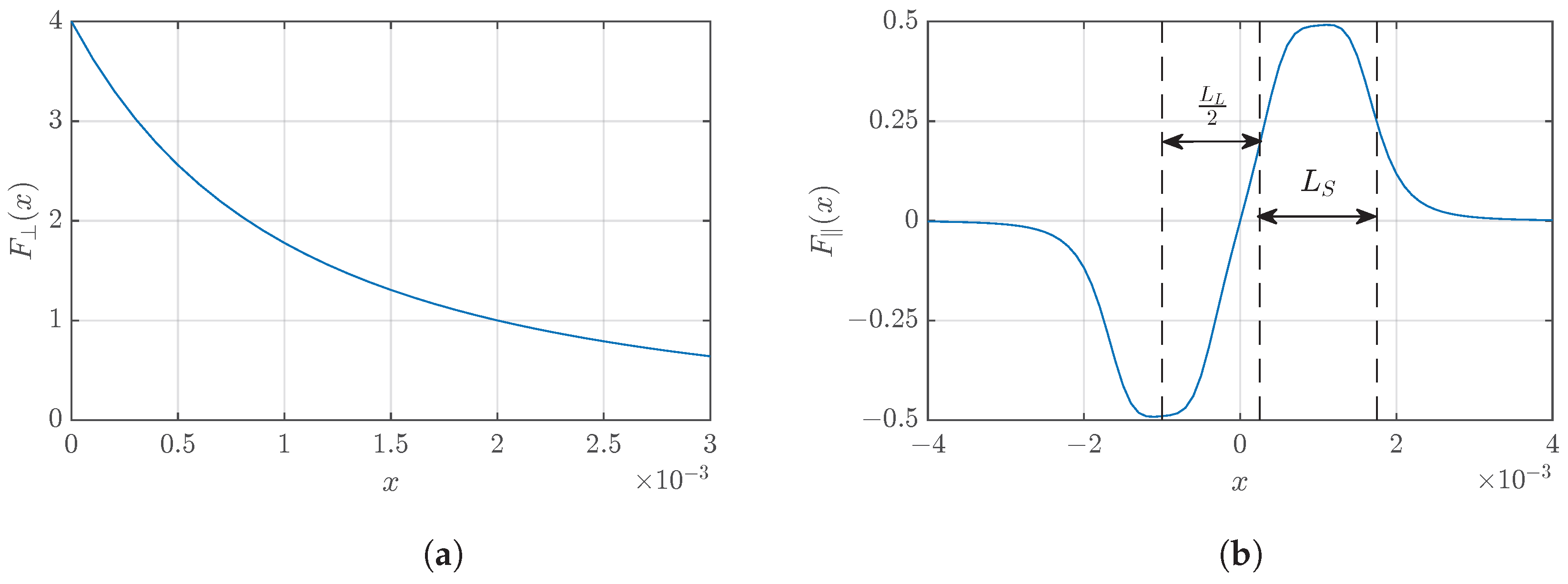
Effective distance between magnets (7) and (8), d e 2 × 10 3 m
Force at close contact for magnets (7) and (8), F 0 4N
Distance between magnets at zero position, D0.0025m
Maximum force between magnets (5) F m 0.5N
Width of the peak at half maximum, L S 2 × 10 3 m
Distance between peaks, L L 2 × 10 3 m
Disclaimer/Publisher’s Note: The statements, opinions and data contained in all publications are solely those of the individual author(s) and contributor(s) and not of MDPI and/or the editor(s). MDPI and/or the editor(s) disclaim responsibility for any injury to people or property resulting from any ideas, methods, instructions or products referred to in the content.

