

Thermodynamic Analysis of the Low-Grade Heat Sources for the Improvement in Efficiency of Oxy–Fuel Combustion Power Cycles


Abstract
:1. Introduction
1.1. Modern Promising Directions of Carbon Dioxide Emissions Control
- Reducing the use of fossil fuels by increasing the efficiency of energy blocks, reducing the consumption of electrical energy, using technologies without CO2 emissions (renewable energy sources, nuclear fuel, environmentally friendly hydrogen), or changing a low carbon and hydrogen ratio C/H (coal, oil products) to gaseous fuels (natural gas);
- Capture of carbon dioxide released during the combustion process and its disposal and beneficial use in oil producing enterprises (intensification of crude oil production, increase in the oil recovery factor);
- Limitation of deforestation processes, thereby increasing the accumulation of CO2 in biomass.
- Pre-combustion carbon capture takes place prior to the combustion process (by gasification of the fuel with oxygen, e.g., integrated coal gasification technology);
- Post-combustion carbon capture takes place after the combustion process (recovery of CO2 from flue gases, e.g., by chemical absorption, physical adsorption, membrane separation, or the use of a chemical circuit);
- Carbon capture by oxy-combustion occurs after the combustion process in an oxygen atmosphere by separating the CO2 produced in the oxy-combustion process. An oxygen atmosphere can be obtained by removing nitrogen from the air before the combustion process in an air separation unit (ASU).
1.2. Ways to Improve the Energy Efficiency of Oxygen–Fuel Power Plants
2. Materials and Methods
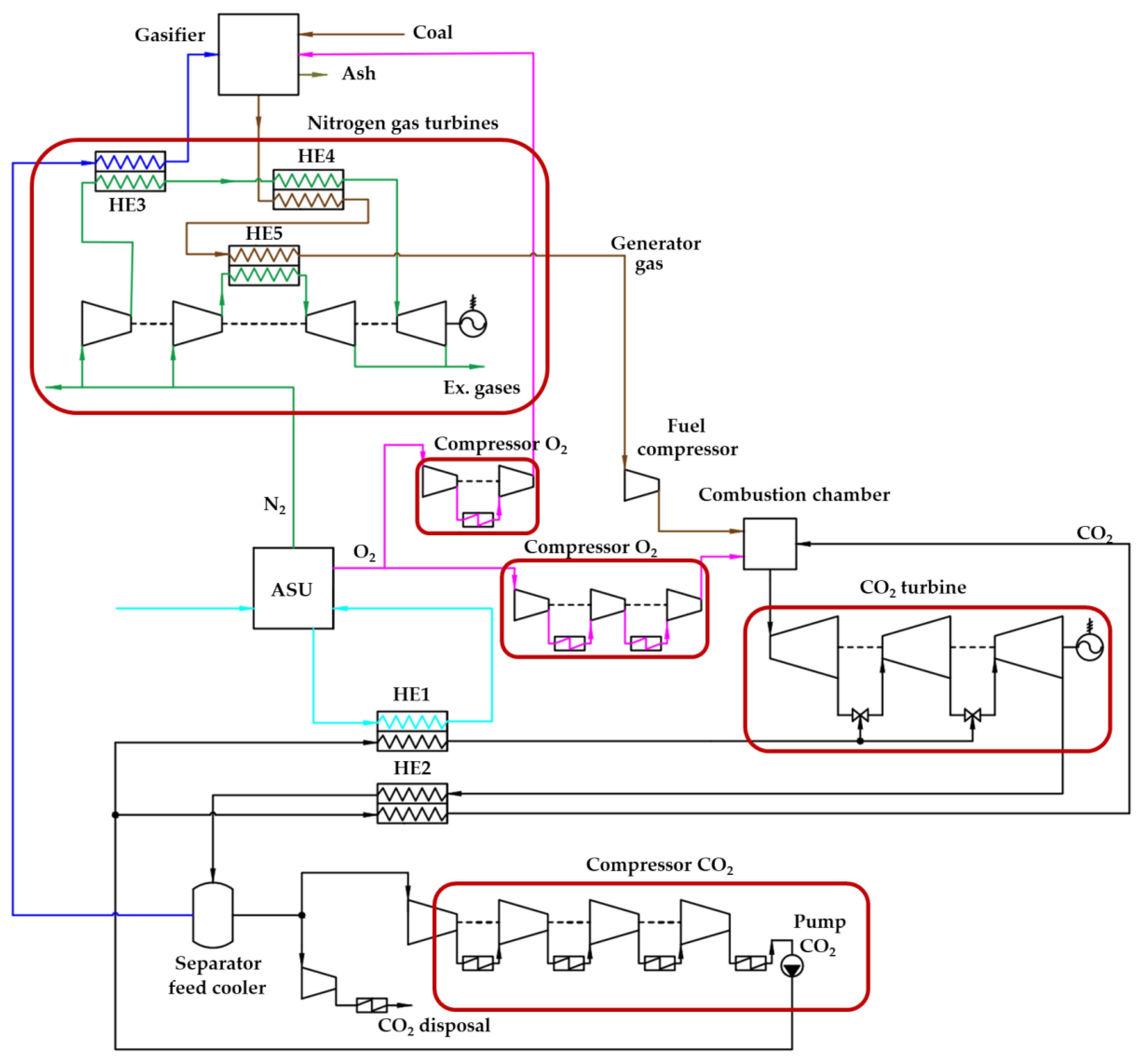
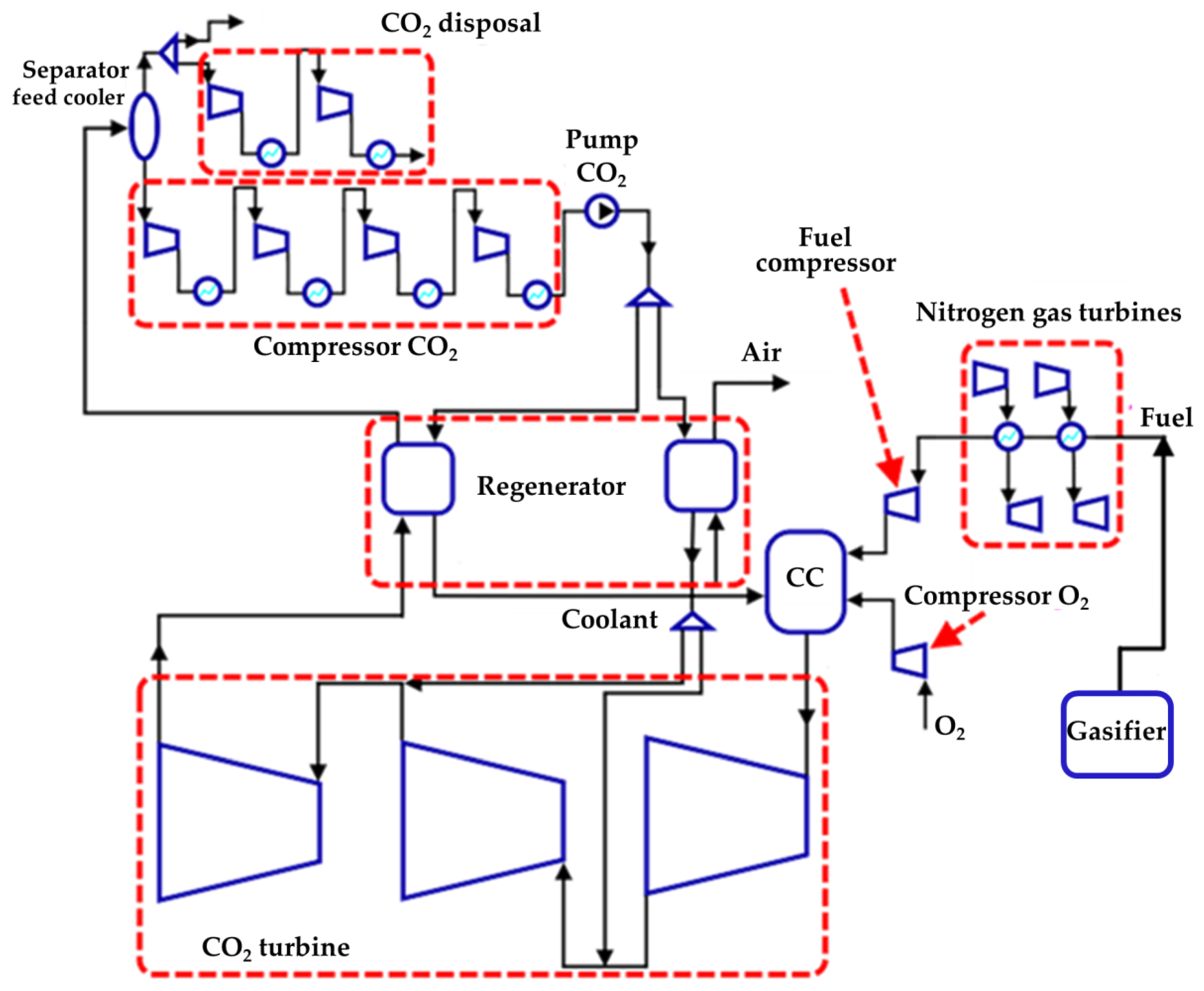
2.1. Research Object
2.2. Modeling Method
- The influence of friction forces in pipelines on the efficiency of the station is not taken into account;
- The model does not take into account the supply of cooling carbon dioxide after each cooled nozzle and blade of the gas turbine;
- In the combustion chamber stoichiometric combustion of synthesis gas;
- The relative internal efficiencies of the compressors, the pump, the CO2 turbine, and the pressure loss in the combustion chamber were assumed to be constant.
3. Results and Discussion
3.1. Study of Low-Potential Heat Sources in the Allam Cycle with Gasification
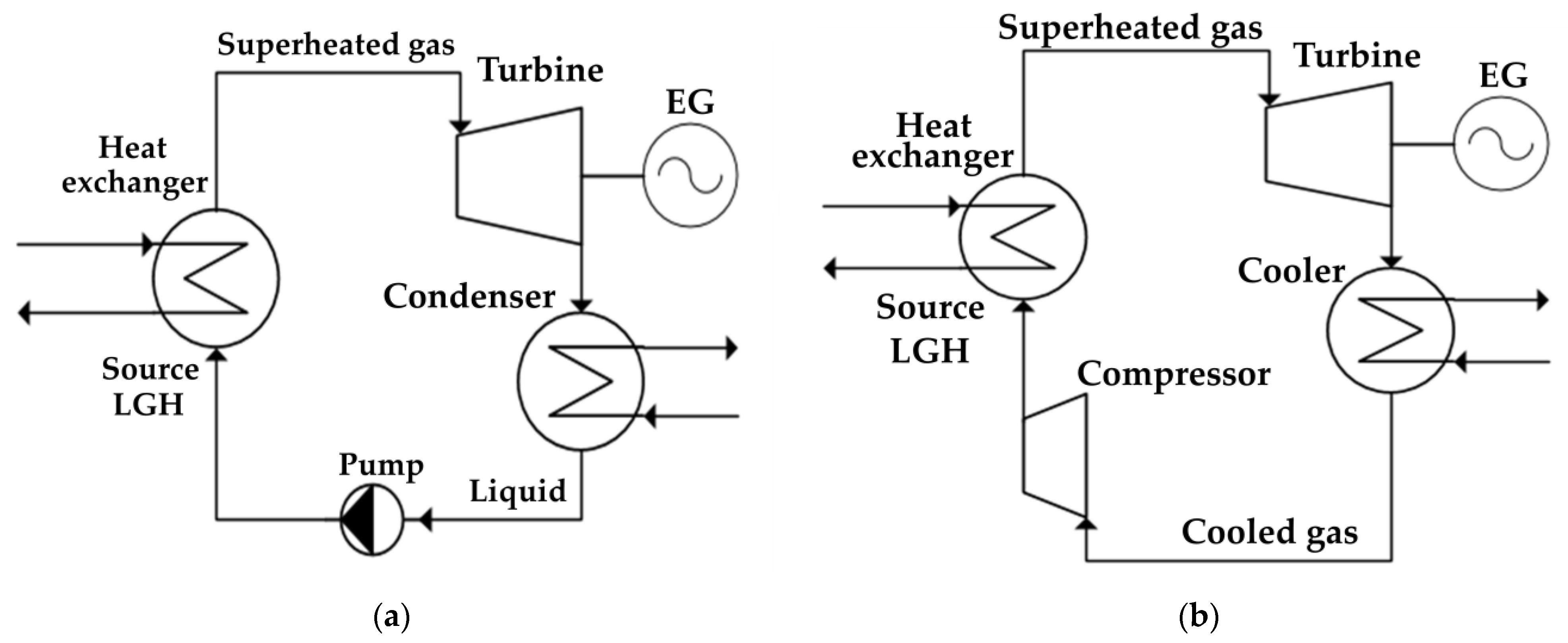
3.2. Study of the Impact of Low-Grade Heat Utilization on Efficiency
4. Conclusions
- This paper proposes new circuit solutions for oxygen–fuel energy complexes operating on the Allam cycle on coal fuel. The main sources of low-potential heat losses are determined and a unified scheme for its utilization is created;
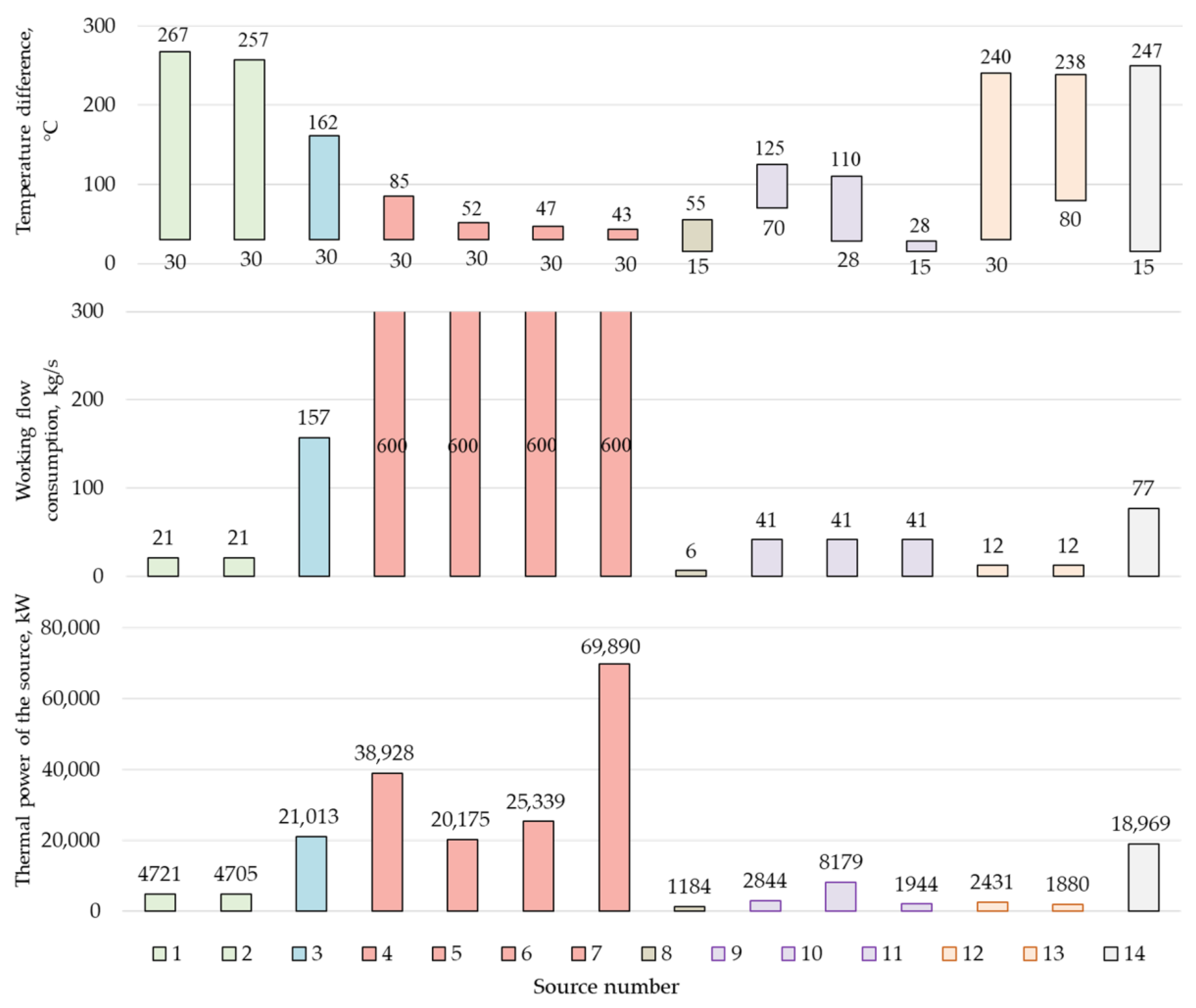
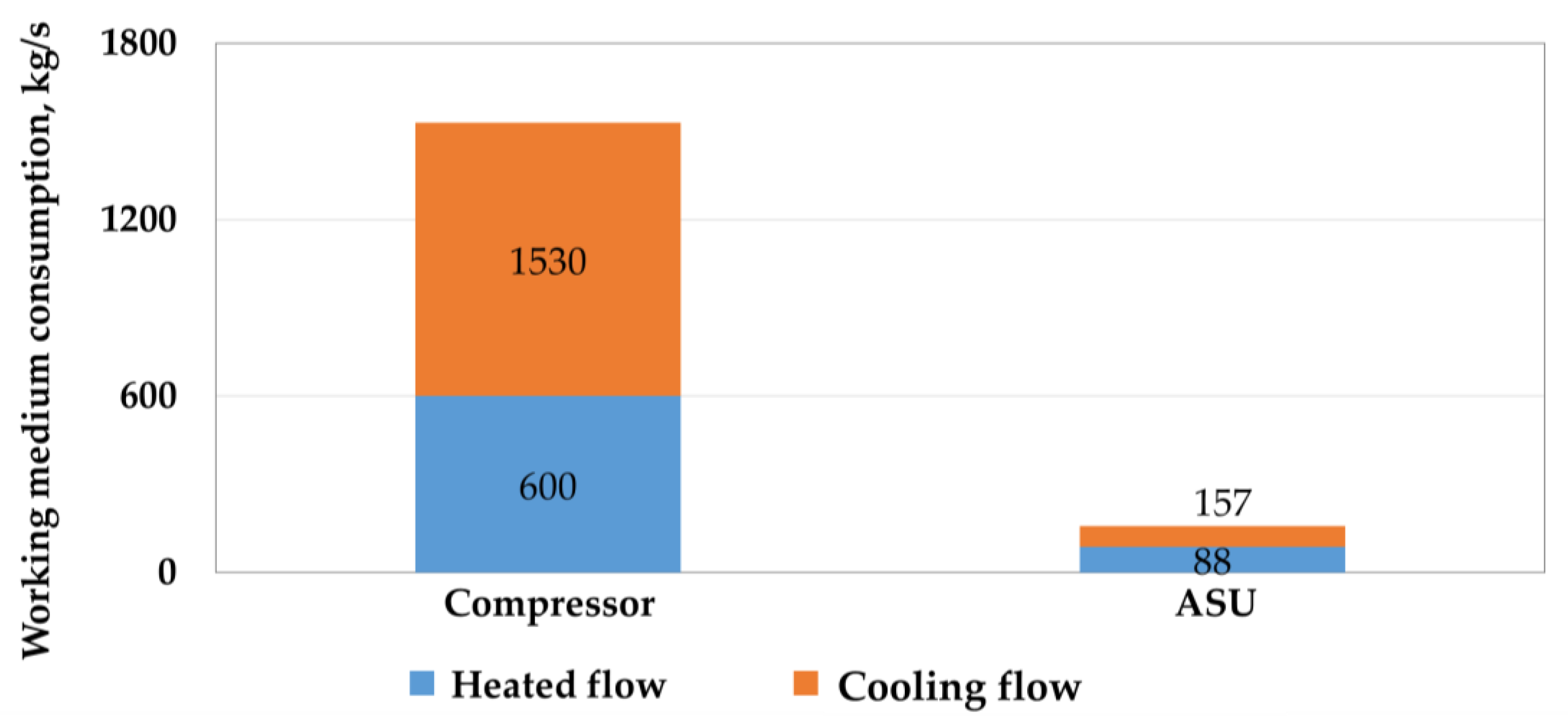
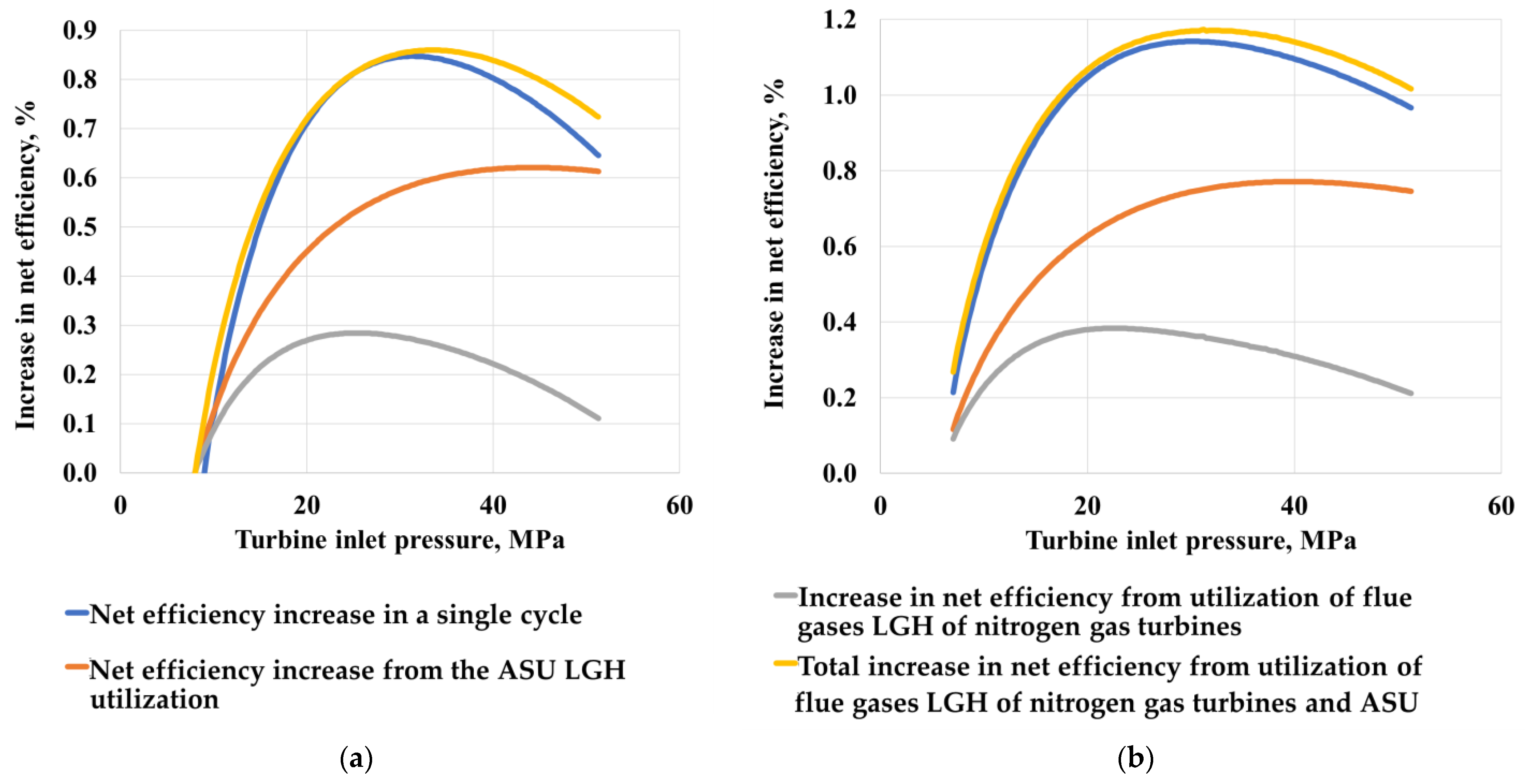
- Several heat sources have the greatest potential for utilization, namely the compressed air flow in front of the ASU and the exhaust gases of nitrogen gas turbines, the total capacity of which is 40 MW. The coolers of the working flow in the carbon dioxide compressor have a high thermal power equal to 154.2 MW. However, these sources operate at low temperatures, due to which a large consumption of a low-boiling flow in the Rankine carbon dioxide cycle (1530 kg/s) is observed with a slight increase in power (2.1 MW);
- It has been established that benzene, due to its thermophysical properties, namely a saturation pressure of 15 kPa and density at 30 °C equal to 868 kg/m3, is the most effective coolant for organic Brayton and Rankine cycles; however, due to its toxicity, its use is contrary to the modern environmental requirements set for humanity. At the same time, carbon dioxide, which is the working heat of the main cycle and a by-product of the energy complex, is the most promising coolant for recycling cycles;
- It was determined that the use of the Rankine carbon dioxide cycle for the utilization of low-grade heat in the main cycle makes it possible to increase the efficiency of the power plant by 1.198%, and the use of the Brayton carbon dioxide cycle increases efficiency by 0.87%. In this regard, we can conclude that it is more expedient to use the organic Rankine cycle as a cycle for the utilization of low-grade heat.
Author Contributions
Funding
Data Availability Statement
Conflicts of Interest
References
- Savaresi, A. The Paris Agreement: A new beginning? J. Energy Nat. Resour. Law 2016, 34, 16–26. [Google Scholar] [CrossRef] [Green Version]
- Tamme, E.; Beck, L.L. European Carbon Dioxide Removal Policy: Current Status and Future Opportunities. Front. Clim. 2021, 3, 682882. [Google Scholar] [CrossRef]
- Zhao, C.; Guo, Y.; Yuan, J.; Wu, M.; Li, D.; Zhou, Y.; Kang, J. ESG and Corporate Financial Performance: Empirical Evidence from China’s Listed Power Generation Companies. Sustainability 2018, 10, 2607. [Google Scholar] [CrossRef] [Green Version]
- Walther, M. Sustainable Electric Power from a Responsible Investing Perspective. In Sustainable Electricity II; Springer: Cham, Switzerland, 2019; pp. 57–74. [Google Scholar]
- Chen, W.; Zhang, G.; Li, B.; Liu, M.; Liu, J. Simulation study on 660 MW coal-fired power plant coupled with a steam ejector to ensure NOx reduction ability. Appl. Therm. Eng. 2017, 111, 550–561. [Google Scholar] [CrossRef]
- Sohn, J.; Hwang, I.S.; Hwang, J. Improvement of ammonia mixing in an industrial scale selective catalytic reduction De-NOx system of a coal-fired power plant: A numerical analysis. Process. Saf. Environ. Prot. 2021, 147, 334–345. [Google Scholar] [CrossRef]
- Ma, T.; Takeuchi, K. Technology choice for reducing NOx emissions: An empirical study of Chinese power plants. Energy Policy 2017, 102, 362–376. [Google Scholar] [CrossRef] [Green Version]
- Dutta, R.; Nord, L.O.; Bolland, O. Selection and design of post-combustion CO2 capture process for 600 MW natural gas fueled thermal power plant based on operability. Energy 2017, 121, 643–656. [Google Scholar] [CrossRef] [Green Version]
- Mahmoudi, R.; Emrouznejad, A.; Khosroshahi, H.; Khashei, M.; Rajabi, P. Performance evaluation of thermal power plants considering CO2 emission: A multistage PCA, clustering, game theory and data envelopment analysis. J. Clean. Prod. 2019, 223, 641–650. [Google Scholar] [CrossRef] [Green Version]
- Kindra, V.O.; Milukov, I.A.; Shevchenko, I.V.; Shabalova, S.I.; Kovalev, D.S. Thermodynamic analysis of cycle arrangements of the coal-fired thermal power plants with carbon capture. Arch. Thermodyn. 2021, 42, 103–121. [Google Scholar]
- Kanniche, M.; Le Moullec, Y.; Authier, O.; Hagi, H.; Bontemps, D.; Neveux, T.; Louis-Louisy, M. Up-to-date CO2 Capture in Thermal Power Plants. Energy Procedia 2017, 114, 95–103. [Google Scholar] [CrossRef]
- Peng, J.; Yu, B.-Y.; Liao, H.; Wei, Y.-M. Marginal abatement costs of CO2 emissions in the thermal power sector: A regional empirical analysis from China. J. Clean. Prod. 2018, 171, 163–174. [Google Scholar] [CrossRef]
- Hong, J.; Chaudhry, G.; Brisson, J.; Field, R.; Gazzino, M.; Ghoniem, A.F. Analysis of oxy-fuel combustion power cycle utilizing a pressurized coal combustor. Energy 2009, 34, 1332–1340. [Google Scholar] [CrossRef] [Green Version]
- Kindra, V.; Rogalev, A.; Zlyvko, O.; Sokolov, V.; Milukov, I. Research and development of a high-performance oxy-fuel combustion power cycle with coal gasification. Arch. Thermodyn. 2021, 42, 155–168. [Google Scholar]
- Kindra, V.; Osipov, S.; Zlyvko, O.; Shcherbatov, I.; Sokolov, V. Thermodynamic analysis of an innovative steam turbine power plant with oxy-methane combustors. Arch. Thermodyn. 2021, 42, 123–140. [Google Scholar]
- Allam, R.; Martin, S.; Forrest, B.; Fetvedt, J.; Lu, X.; Freed, D.; Brown, G.W., Jr.; Sasaki, T.; Itoh, M.; Manning, J. Demonstration of the Allam Cycle: An Update on the Development Status of a High Efficiency Supercritical Carbon Dioxide Power Process Employing Full Carbon Capture. Energy Procedia 2017, 114, 5948–5966. [Google Scholar] [CrossRef]
- Zhu, Z.; Chen, Y.; Wu, J.; Zhang, S.; Zheng, S. A modified Allam cycle without compressors realizing efficient power generation with peak load shifting and CO2 capture. Energy 2019, 174, 478–487. [Google Scholar] [CrossRef]
- Thomas, C.E. Petroleum and coal proven reserves: The case for coal and the demise of OPEC. In Stopping Climate Change: The Case for Hydrogen and Coal; Springer: Cham, Switzerland, 2017; pp. 35–40. [Google Scholar]
- Maddahi, L.; Hossainpour, S. Thermo- economic evaluation of 300 MW coal based oxy-fuel power plant integrated with organic Rankine cycle. Int. J. Greenh. Gas Control 2019, 88, 383–392. [Google Scholar] [CrossRef]
- Rogalev, A.; Rogalev, N.; Kindra, V.; Zlyvko, O.; Vegera, A. A Study of Low-Potential Heat Utilization Methods for Oxy-Fuel Combustion Power Cycles. Energies 2021, 14, 3364. [Google Scholar] [CrossRef]
- Mitchell, C.; Avagyan, V.; Chalmers, H.; Lucquiaud, M. An initial assessment of the value of Allam Cycle power plants with liquid oxygen storage in future GB electricity system. Int. J. Greenh. Gas Control 2019, 87, 1–18. [Google Scholar] [CrossRef]
- Allam, R.J.; Fetvedt, J.E.; Forrest, B.A.; Freed, D.A. The Oxy-Fuel, Supercritical CO2 Allam Cycle: New Cycle Developments to Produce Even Lower-Cost Electricity From Fossil Fuels Without Atmospheric Emissions. In Volume 3B: Oil and Gas Applications; Organic Rankine Cycle Power Systems; Supercritical CO2 Power Cycles; Wind Energy; American Society of Mechanical Engineers: Düsseldorf, Germany, 2014; p. V03BT36A016. [Google Scholar]
- Hung, T.; Wang, S.; Kuo, C.; Pei, B.; Tsai, K. A study of organic working fluids on system efficiency of an ORC using low-grade energy sources. Energy 2010, 35, 1403–1411. [Google Scholar] [CrossRef]
- Drescher, U.; Brüggemann, D. Fluid selection for the Organic Rankine Cycle (ORC) in biomass power and heat plants. Appl. Therm. Eng. 2007, 27, 223–228. [Google Scholar] [CrossRef]
- Branchini, L.; De Pascale, A.; Peretto, A. Systematic comparison of ORC configurations by means of comprehensive performance indexes. Appl. Therm. Eng. 2013, 61, 129–140. [Google Scholar] [CrossRef]
- Ho, C.K.; Carlson, M.; Garg, P.; Kumar, P. Technoeconomic Analysis of Alternative Solarized s-CO2 Brayton Cycle Configurations. J. Sol. Energy Eng. 2016, 138, 051008. [Google Scholar] [CrossRef]
- Wang, L.; Pan, L.-M.; Wang, J.; Chen, D.; Huang, Y.; Hu, L. Investigation on the temperature sensitivity of the S-CO2 Brayton cycle efficiency. Energy 2019, 178, 739–750. [Google Scholar] [CrossRef]
- Kindra, V.; Rogalev, A.; Zlyvko, O.V.; Zonov, A.; Smirnov, M.; Kaplanovich, I. Research on oxy-fuel combustion power cycle using nitrogen for turbine cooling. Arch. Thermodyn. 2020, 41, 191–202. [Google Scholar]
- Shevchenko, I.V.; Rogalev, N.D.; Kindra, V.O.; Osipov, S.K.; Rostova, D.M. Numerical analysis of the influence of turbulators constructive features on heat transfer in gas turbine blade cooling channels. Int. J. Appl. Eng. Res. 2017, 12, 6853–6861. [Google Scholar]
- Chan, W.; Lei, X.; Chang, F.; Li, H. Thermodynamic analysis and optimization of Allam cycle with a reheating configuration. Energy Convers. Manag. 2020, 224, 113382. [Google Scholar] [CrossRef]
- Cormos, C.C. Integrated assessment of IGCC power generation technology with carbon capture and storage (CCS). Energy 2012, 42, 434–445. [Google Scholar] [CrossRef]
- Matuszewska, D. Molecular Complexity of Working Fluids Dedicated to Organic Rankine Cycle (ORC). In IOP Conference Series: Materials Science and Engineering; IOP Publishing: Bristol, UK, 2020; Volume 946, p. 012008. [Google Scholar]
- Liu, Z.; Yang, X.; Liu, X.; Yu, Z.; Chen, Y. Performance assessment of a novel combined heating and power system based on transcritical CO2 power and heat pump cycles using geothermal energy. Energy Convers. Manag. 2020, 224, 113355. [Google Scholar] [CrossRef]
- Ahn, Y.; Bae, S.J.; Kim, M.; Cho, S.K.; Baik, S.; Lee, J.I.; Cha, J.E. Review of supercritical CO2 power cycle technology and current status of research and development. Nucl. Eng. Technol. 2015, 47, 647–661. [Google Scholar] [CrossRef] [Green Version]
- Liu, Y.; Wang, Y.; Huang, D. Supercritical CO2 Brayton cycle: A state-of-the-art review. Energy 2019, 189, 115900. [Google Scholar] [CrossRef]
- Ebrahimi, A.; Meratizaman, M.; Reyhani, H.A.; Pourali, O.; Amidpour, M. Energetic, exergetic and economic assessment of oxygen production from two columns cryogenic air separation unit. Energy 2015, 90, 1298–1316. [Google Scholar] [CrossRef]


| Way to Increase Efficiency | Increase in Net Efficiency When Operating on Natural Gas/Coal, % | Advantages | Disadvantages | Source |
|---|---|---|---|---|
| Utilization of heat from low-potential sources in the organic/carbon dioxide Rankine cycle | –/1.51 * | 1. Increased power generation and thermal efficiency of the cycle through deeper heat utilization. | 1. Additional capital costs for equipment. | [19] |
| Utilization of heat from low-grade sources in the carbon dioxide Brighton cycle | 0.2/– | 1. Increased power generation and thermal efficiency of the cycle through deeper heat utilization. 2. The possibility of replenishing the losses of the working fluid from the main cycle. | 1. Additional capital costs for equipment. | [20] |
| Water injection into CO2 turbine coolant flows | 2.2/– | 1. Reducing coolant consumption by increasing its heat capacity. 2. Water can be taken from the separator cooler; therefore, no additional costs for its preparation are required. | 1. Danger of water vapor condensation in the channels of the cooled turbine blades, which can lead to a sharp increase in thermal stresses. 2. Additional own costs for injecting water into the coolant flows. | [29] |
| Pre-cooling of the carbon dioxide turbine coolant in a surface heat exchanger | 3.2/– | 1. Cooling occurs without additional costs for own needs and coolant preparation. | 1. Additional capital costs for heat exchange equipment. | [29] |
| Switching to nitrogen coolant for a carbon dioxide turbine | 2.4/– | 1. Beneficial use of a by-product in the production of oxygen in ASU. 2. Elimination of underproduction of electricity due to the direction of the cold compressed CO2 flow to cool the gas turbine stages. 3. Elimination of additional gas-dynamic losses in the flow of the working fluid by organizing a closed cooling system. | 1. The organization of a closed cooling system requires the introduction of an additional compressor for nitrogen and a complex topology of the cooled channels. | [28] |
| Condensation of the carbon dioxide working flow before compression (Allam-Z) | 2/– | 1. Increasing the thermal efficiency of the cycle with the same initial parameters. | 1. Condensation of CO2 requires a low temperature for the cold source during the entire operation time. 2. Pump operation in the near-critical zone. | [23] |
| Production of liquid oxygen using air separation plants | 17.67 **/– | 1. Expansion of the control range due to the accumulation of liquid oxygen in the reserve tanks. | 1. Additional capital costs for the liquid oxygen storage system. | [21] |
| Parameters | Value |
|---|---|
| Atmospheric pressure, MPa | 0.1 |
| Atmospheric temperature, °C | 15 |
| Syngas pressure, MPa | 4 |
| Turbine inlet temperature, °C | 1100 |
| Turbine inlet pressure, MPa | 30 |
| Turbine outlet pressure, °C | 3 |
| Turbine coolant temperature, MPa | 200 |
| CO2 compressor mass flow, kg/s | 600 |
| Gas turbine and compressors’ isentropic efficiency, % | 90 |
| Pumps isentropic efficiency, % | 75 |
| Multi-flow regenerator pinch-point temperature difference, °C | 5 |
| Turbine, power generator, and compressors’ mechanical efficiency, % | 99 |
| Pumps mechanical efficiency, % | 95 |
| Power generator and electric motor efficiency, % | 99 |
| Cooler-separator exit working flow temperature, °C | 55 |
| Oxygen purity, % | 30 |
| Nitrogen turbine inlet temperature, °C | 750 |
| Nitrogen turbine inlet pressure, MPa | 30 |
| Working flow temperature at the compressor inter-cooler outlet, °C | 30 |
| Parameter | Value |
|---|---|
| Moisture, % | 8.10 |
| Ash, % | 14.19 |
| Carbon, % | 72.04 |
| Hydrogen, % | 4.08 |
| Nitrogen, % | 1.67 |
| Oxygen, % | 7.36 |
| Sulphur, % | 0.65 |
| Chlorine, % | 0.01 |
| Volatile substances, % | 28.51 |
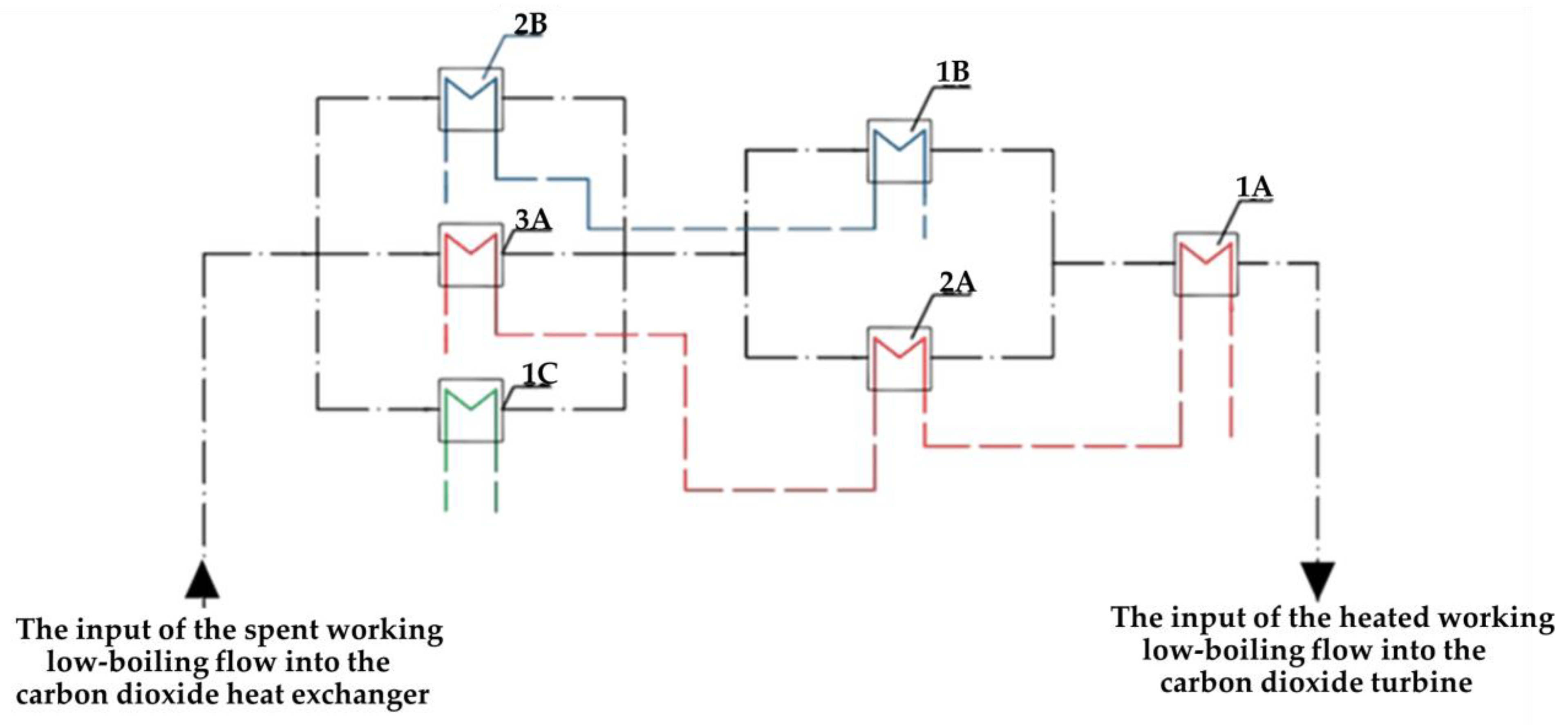
| LGH Source | Temperature at the HE Inlet, °C | Temperature at the HE Outlet, °C | Installation Sequence |
|---|---|---|---|
| Flue gas cooler for the first nitrogen turbine | 322 | 178 | 1A |
| 178 | 142 | 2A | |
| 142 | 50 | 3A | |
| Flue gas cooler for the second nitrogen turbine | 322 | 178 | 2B |
| 178 | 142 | 3B | |
| ASU | 142 | 50 | 3C |
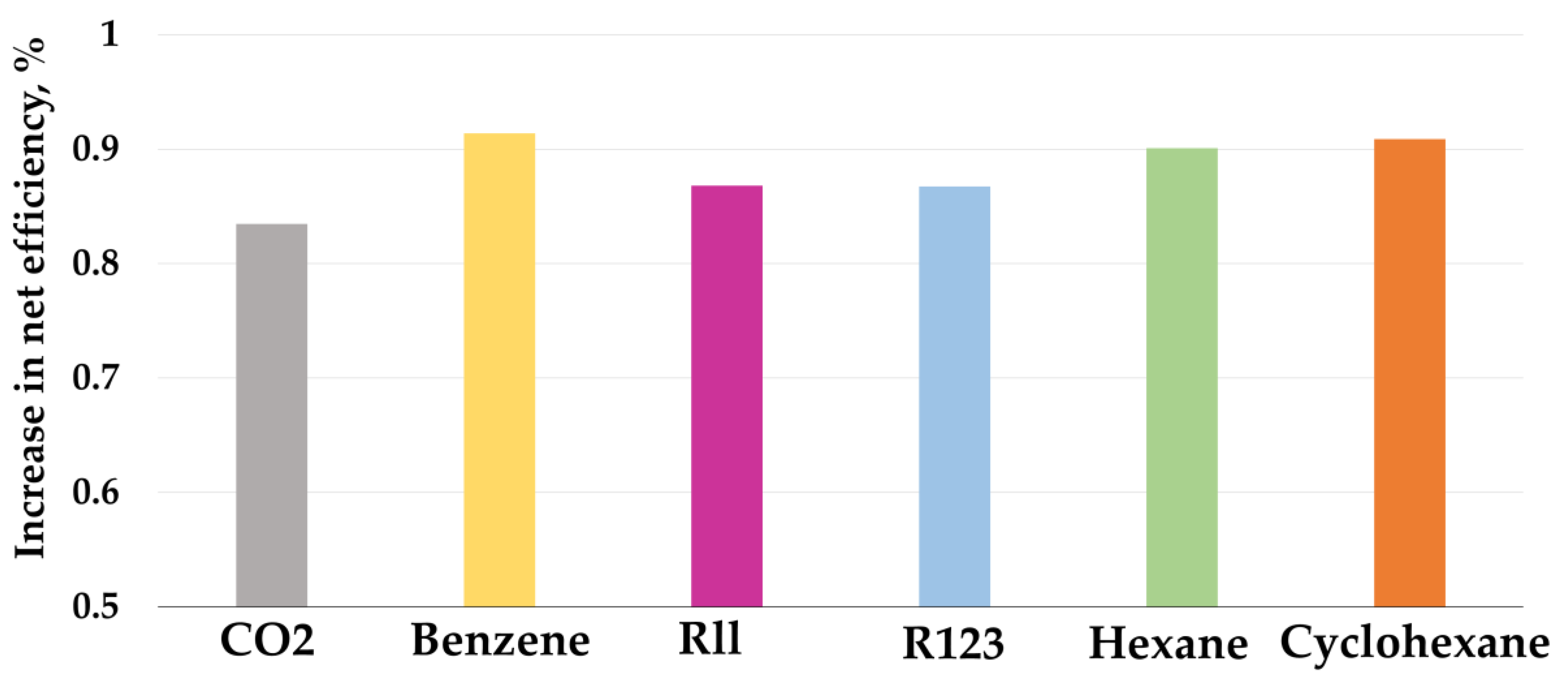
| Working Fluid | CO2 | Benzene | R11 | R123 | Hexane | Cyclohexane |
|---|---|---|---|---|---|---|
| Turbine capacity, MW | 10,767 | 4642 | 4557 | 4463 | 4753 | 4718 |
| Consumed power of the utilizing cycle pump, kW | 6843 | 347 | 477 | 385 | 519 | 446 |
| Power generated by the utilization cycle, kW | 3924 | 4295 | 4080 | 4078 | 4234 | 4272 |
| Net efficiency of the utilization cycle, % | 18.25 | 19.98 | 18.98 | 18.97 | 19.69 | 19.87 |
| Increase in net efficiency, % | 0.835 | 0.914 | 0.868 | 0.868 | 0.901 | 0.909 |
Disclaimer/Publisher’s Note: The statements, opinions and data contained in all publications are solely those of the individual author(s) and contributor(s) and not of MDPI and/or the editor(s). MDPI and/or the editor(s) disclaim responsibility for any injury to people or property resulting from any ideas, methods, instructions or products referred to in the content. |
© 2023 by the authors. Licensee MDPI, Basel, Switzerland. This article is an open access article distributed under the terms and conditions of the Creative Commons Attribution (CC BY) license (https://creativecommons.org/licenses/by/4.0/).
Share and Cite
Komarov, I.; Kindra, V.; Pisarev, D.; Kovalev, D.; Lvov, D. Thermodynamic Analysis of the Low-Grade Heat Sources for the Improvement in Efficiency of Oxy–Fuel Combustion Power Cycles. Inventions 2023, 8, 16. https://doi.org/10.3390/inventions8010016
Komarov I, Kindra V, Pisarev D, Kovalev D, Lvov D. Thermodynamic Analysis of the Low-Grade Heat Sources for the Improvement in Efficiency of Oxy–Fuel Combustion Power Cycles. Inventions. 2023; 8(1):16. https://doi.org/10.3390/inventions8010016
Chicago/Turabian StyleKomarov, Ivan, Vladimir Kindra, Dmitry Pisarev, Dmitriy Kovalev, and Dmitriy Lvov. 2023. "Thermodynamic Analysis of the Low-Grade Heat Sources for the Improvement in Efficiency of Oxy–Fuel Combustion Power Cycles" Inventions 8, no. 1: 16. https://doi.org/10.3390/inventions8010016