Article

QFD and SDE Methods Applied to Autonomous Minibus Redesign and an Innovative Mobile Charging System (MBS)

Alma Mater Studiorum–Università di Bologna, 40136 Bologna, Italy
*
Author to whom correspondence should be addressed.
Inventions 2023, 8(1), 1; https://doi.org/10.3390/inventions8010001
Submission received: 15 November 2022 / Revised: 11 December 2022 / Accepted: 15 December 2022 / Published: 21 December 2022
(This article belongs to the Collection Feature Innovation Papers)

Abstract

:
Urban mobility scenarios are constantly evolving, and today’s solutions may not be adequate in the future. Through innovative analysis and design methods encapsulated by the IDeS methodology, it is possible to plausibly hypothesize a number of key scenarios to be analyzed, for which vehicles can be designed in order to solve the main problems. Scenarios such as the steady growth in public mobility, based on the sharing of electric mini-buses at the expense of the privatization of the means of transport, lead to the gradual rethinking of citizens’ needs and the supporting infrastructure. Problems such as the lack of privacy of public vehicles, the efficiency of the infrastructure and recharging modes of e-buses, and autonomous driving are addressed here through methods such as QFD (quality function deployment) and SDE (stylistic design engineering), with the aim of outlining a proposal that, to date, is futuristic but is designed to be concrete and feasible within the next decade. These methodologies were applied to the design of a sustainable urban transport system consisting of an electric mini-bus, effected by rethinking the layout of the interior spaces in favor of areas enabling greater privacy and a mobile recharging system (MBS) capable of offering a new management strategy for the non-stop recharging phase. Through the use of an MBS, which functions as a mobile ‘energy bank’ module that is capable of autonomously reaching a mini-bus in need of recharging and extending its autonomy by connecting and recharging it, the proposed system can potentially be enabled to perform its required service during the day without any need to spend time making intermediate stops for the purpose of recharging.

1. Introduction

This project originates from considerations related to research concerning the current and future changes that the urban transport sector is and will be facing in the coming decades. New technologies and new solutions are, in fact, continuously developing in an attempt to address the problems caused by the environmental impact of vehicles, as well as the inefficiencies demonstrated by a system which, today, presents the coexistence of contrasting strategies and technologies in this era of transition. Nowadays, urban mobility is characterized by traffic congestion, pollution, non-optimized timings, low average speeds due to the density of the vehicles, noise, and general inefficiency in terms of capacity and space consumption on the scale required to enable a modern urban economy to function productively. According to the EEA 2013 report [1], urban transport is estimated to account for approximately 25% of the CO2 transport emissions responsible for climate change. Research [2] shows that the viable solutions that can enable future urban mobility are shared and electric vehicles. In fact, the adoption of electric buses in the urban public transport fleet is steadily growing all over the world. The transition began in China, and Europe is now booming; the year 2019 saw the number of registrations of electric buses in western Europe triple. In 2020, the year of COVID-19, the number of battery electric buses in the same area of the world grew by 22%. Marcus Enoch’s research for New Zealand’s Ministry of Transport explores four visions for the future of public transport [3], showing how people might travel in the year 2045. Based on two axes of change, one considering the level of automation and the other considering the cities’ density, the four scenarios can be divided as follows: the shared shuttles and minibuses that allow for a reduced environmental impact by encouraging a community approach; the corridors connected, which enable extreme organization for the transition from autonomous to intelligent public transport through a single APP; the mobility market, a prepaid “package” enabling individuals to travel routes using different means of transport (bike hire, car-pooling, taxi, etc.); and the spread of private “pods”, which are capsules with a sharing option to reduce travel costs. The aim of the proposed project is to define a possible solution to the case defined by the first abovementioned scenario. The sharing of vehicles such as shuttles and minibuses could improve the environmental aspect not only by reducing the high motorization rate but also, at the same time, by exploiting the positive trend towards vehicle electrification. For a future scenario in which automation could be consolidated, an innovative mobile recharge system (MBS) is proposed, which is capable of extending the autonomy range of minibuses while guaranteeing optimal public service combined with the preservation of privacy, which could be lost with the abandonment of private vehicles. In the following sections, the research on the sustainability of the proposed solution is strengthened and discussed, together with the competing (current and future) infrastructures and systems for the optimization of urban mobility. Subsequently, the identification of the project requirements using the QFD method is addressed, as well as the stylistic requirements through the SDE methodology. The research results regarding the system defined by minibuses and MBS, of which the technical requirements and logistics are addressed and discussed, are also presented.

2. Environmental Analysis

The road transport sector is constantly changing, anticipating and shifting towards a theoretically more sustainable and service-based future. All over the world, the transport sector is responsible for most of the greenhouse gas (GHG) emissions produced [4], suggesting the necessity of the transition from ICEVs (internal combustion engine vehicles) to EVs (electric vehicles). Bus-based transportation is the most widely used method for the journeys of passengers on urban and interurban routes worldwide [5]. Therefore, a consistent change is dependent on the shift towards bus electrification. Nevertheless, the carbon footprint and sustainability issues will not be resolved until traffic jams and the lack of parking spots start to impact the quality of life in cities. A further potential strategy that may be used to reduce the emissions, from an operational perspective, would be the use of shared and privately owned automated vehicles. Little is known about the impacts of public and shared automated vehicles, given that they are not yet widely used. According to a recent study [6], by approximating an optimization model of a shared AEV (automated electric vehicle) fleet with two different seating capacities and that of a privately owned one whose characteristics are derived from travel demand data, it is possible to conduct a life cycle assessment (LCA) of the two models. The results show that compared to private AEVs, the shared ones with a capacity for four passengers per vehicle can reduce the system’s environmental impact by up to 42%, chiefly reducing the degree of human toxicity, mineral resource scarcity, and marine and freshwater ecotoxicity. Other studies evaluating the possible impacts of AEVs on the environment confirm that their benefits depend on the acceptance of shared mobility [7], but other factors, such as penetration levels and the interaction with other modes of transport, are also relevant. Some negative aspects are related, however, to a significant decrease in the trip time and user tendencies and habits. On the other hand, there are multiple incentives for the development of automation in the context of mobility, since its purpose is to solve the problem of accident fatalities (estimated to amount to 1.3 million annual deaths globally) and to significantly reduce the number of stops made by vehicles throughout their journeys, among other human aspects, such as driving stress. Unfortunately, it is considered that the maximum benefit will be reached at the level 5 stage of automation. As many authors estimate, this limitation will inevitably result in the inability to reach a high number of AEVs on the roads within the next 25 years.

3. Infrastructures and Competing Concepts

Nowadays, with the continuous and constant electrification of public transport, the topic of infrastructure management and efficiency is gradually gaining increasing interest. The increasing demand for energy from the city’s public power grid has led to a certain level of concern about the impact of the entire infrastructure on the power grid itself, resulting in effective environmental sustainability and economic viability. The objective of the research included in this paper is to present a brief overview of the multiple approaches to this problem that are currently being studied and to understand which issues are being addressed most effectively and the solutions that have already been hypothesized. All of the studies analyzed here focus mainly on the mode of energy delivery, considering either the fast-charging or battery swapping option, with the subsequent management and positioning of the charging stations achieved by means of mathematical systems and models, based on which calculations are performed to delineate the efficiency of the system and its economic viability [8]. The fast-charging option seems to be one of the most common and most widely studied, as with a power of around 500 kW, it allows a good percentage of the battery to be charged very quickly. Although this option makes it possible to considerably reduce the stopping times of e-buses, it also implies a number of disadvantages, the adoption and planning of compulsory stops for recharging the vehicle, and the problem of peek demand charges [9], a fundamental component of the calculation of the cost of electricity that can considerably compromise the economic sustainability of the infrastructure itself. Studies that focused on the strategic planning of fast-charging BEB systems took into account the scheduling of BEB charging through mathematical models [10,11,12]. The proposed charging schedules, however, were typically too simplistic and did not apply to real-world situations. A further application of the mathematical models is battery swapping. The main components of a battery exchange system are the battery exchange station, the storage system, a charging system, a battery delivery system, and a lane system. The electric vehicle, which, in this case, is an electric bus, arrives at the exchange station and interacts with the exchange system, which replaces the discharged battery with a fully charged one within a few minutes. In these cases, the proposed models serve to offer a hypothesis on the timing and positioning of the battery exchange stations [13,14,15,16]. The aim of this solution is to increase the battery life through ensuring a lower degree of degradation during the charging phase compared to fast charging. All the studies presented here found that it is still necessary to stop the electric bus for a certain time in order to render charging possible. In this paper, the aim is to propose an innovative solution that eliminates this necessity.

4. Materials and Methods

The realization of this model follows several steps that are described below. Using the SDE and QFD methods [17,18], it was possible to highlight, using matrices, the main requirements on which the project was established. Later, studying some technical requirements related to the power supply and autonomous driving, the development of the entire minibus, including the chassis, body, and interior, was carried out. With the MBS, not only the technical and aesthetic components but also the logistics components related to the optimization of the vehicle’s charging were studied.

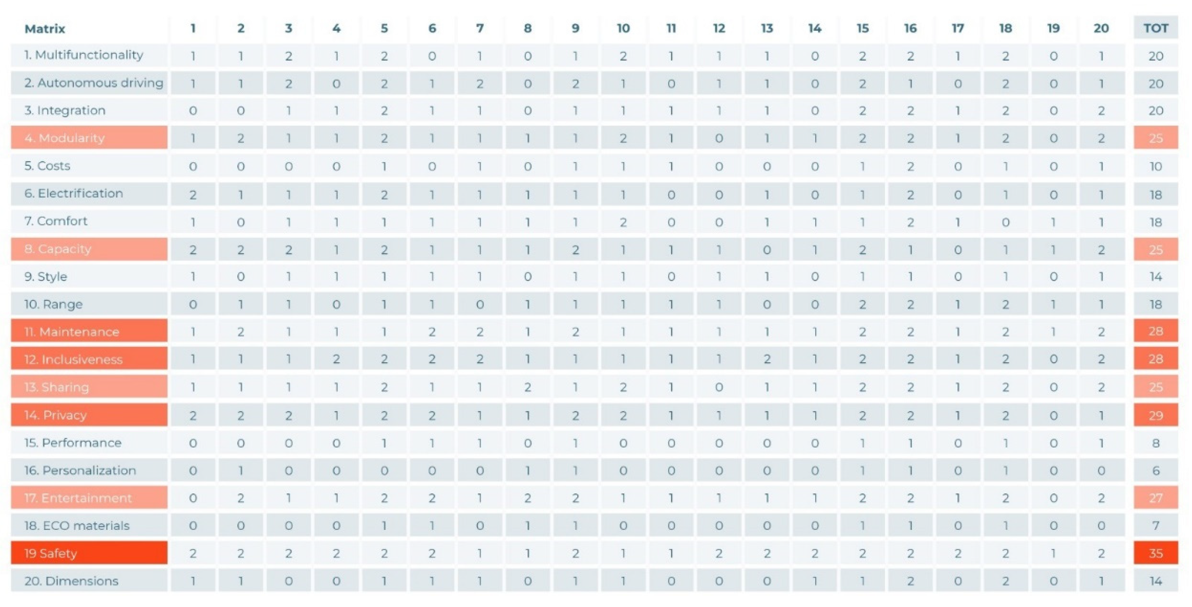
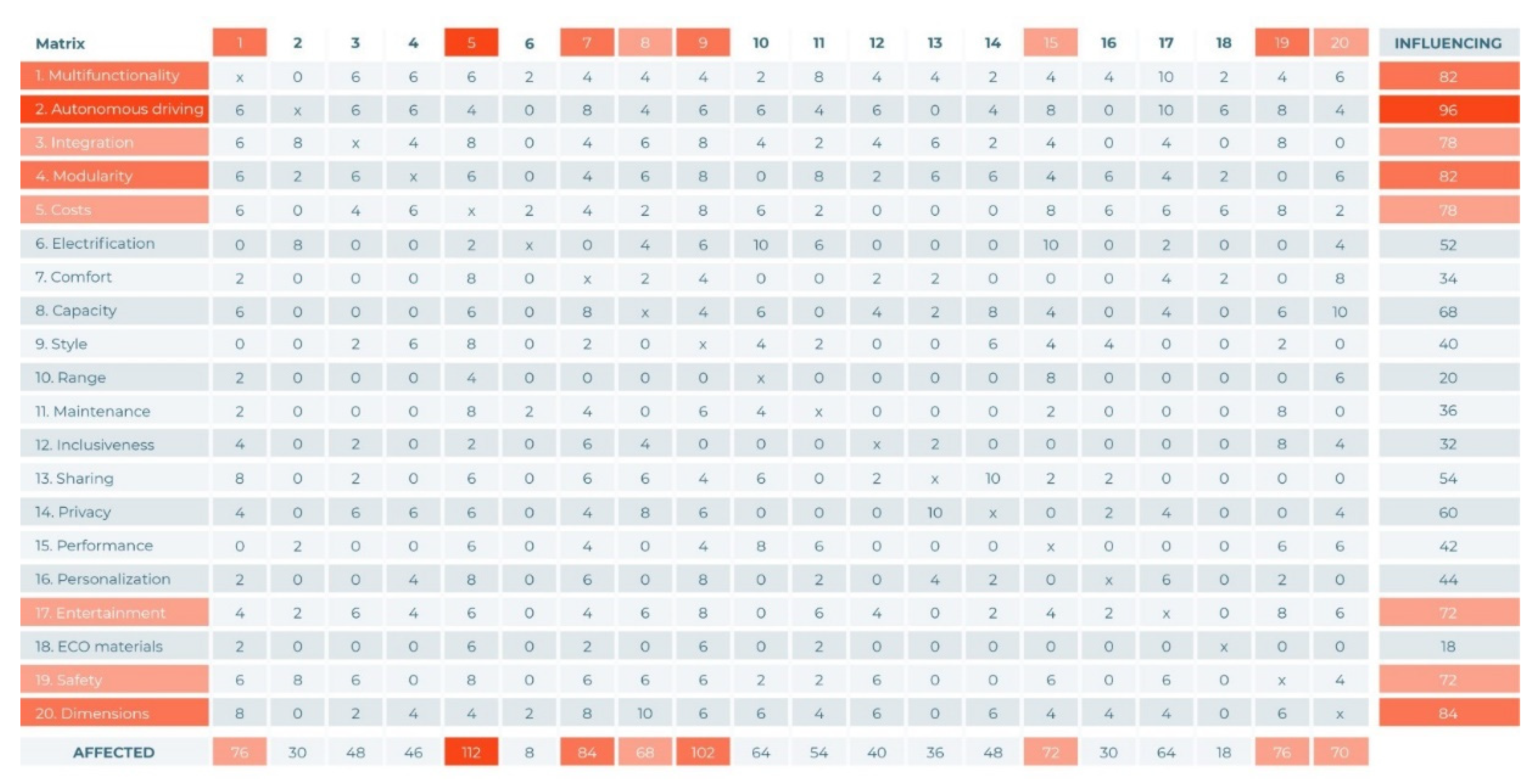
4.1. Application of the QFD Method

The QFD (quality function deployment) method helps us to define the demands of the final user and to meet the goals set for the development of the innovative design. This methodology places the emphasis on the needs of the customer, and it can convert them into detailed engineering specifications so as to produce the products. The application of this methodology is, therefore, extremely useful, because it enables product specifications to be obtained which will truly satisfy future customers. The QFD methodology is based on the following six key questions: who, when, why, what, how, and where. Finally, the QFD’s output sets the requirements necessary to explain the relative importance and dependence–independence matrices. In this way, the requirements to be followed are then defined. In this study, first, all the abled and disabled people of all demographics were identified as the users, and the period of realization considered was the year 2040, by which point private transportation will not be as commonly and widely used, with the aim of optimizing the amount of personal time and space. Following these considerations, we decided to design a sustainable minibus for densely populated cities. An electric self-driving minibus with designated private areas and a mobile battery system was developed. After determining the customer’s needs, multiple parameters were analyzed. By defining the relative importance matrix and the independent matrix, the most important parameters were determined, as were the relationships between them. These parameters can be divided into different fundamental themes, such as security, dimensions, personalization, modularity, the level of electrification, style, and others, which are reported in Figure 1 and Figure 2. Specifically, the relative importance matrix (Figure 1) was used to determine the most important parameters. The question that arises is whether or not an element in the row is more important than another in the column. The values attributed are 0 if it is less important, 1 if it has the same importance, and 2 if it is more important (Figure 1). The sum of the values in the rows indicates the absolute importance of the parameter. As shown below, the most important ones, which are highlighted, are security, privacy, inclusiveness, maintenance, sharing, modularity, capacity, and entertainment. In contrast, the independence matrix (Figure 2) is used to establish dependence and independence relationships between the parameters. One wonders what the nature of the dependence is between the element in the row and that in the column. The values attributed are 0 if there is no dependence, 1 if it is weak, 3 if it is of a medium level, and 9 if it is strong (Figure 2).
The sum of the rows measures the dependence of the elements in that row on the others. The sum of the columns, in contrast, gives us the value of the influence of a certain parameter on the others. Overall, the most influential ones are autonomous driving, dimensions, multifunctionality, modularity, and integration.

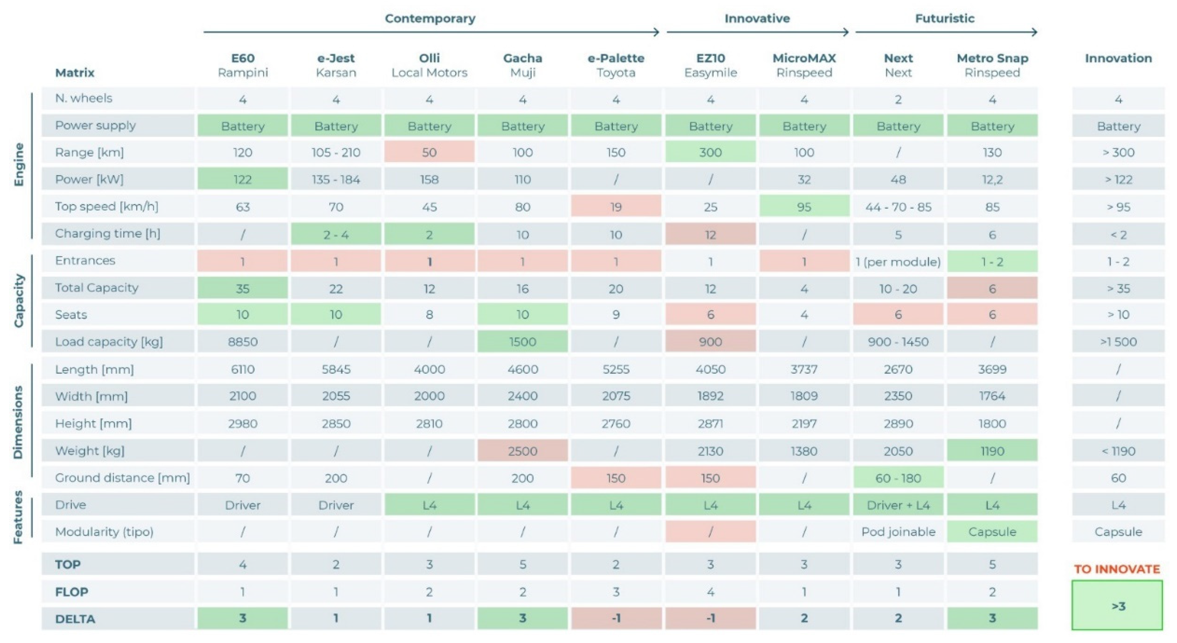
Benchmarking and Top-Flop Analysis

Through the QFD method, the sector in which the project is designed to be applied was identified. At this stage, it is necessary to ask what products are already on the market so as to compare their distinctive characteristics and to design an asset with better properties. Using the top-flop analysis (Figure 3) method, the best and worst values were highlighted for each technical specification of the models compared. The analysis was carried out based on 9 models of city minibuses developed by different companies. The selected competitors were the following: E60 (Rampini), e-Jest (Karsan), Olli (Local Motors), Gacha (Muji), e-palette (Toyota), EZ10 (Easymile), MicroMAX (Rinspeed), NEXT (Next), and Metro Snap (Rinspeed). The next step was to collect the technical specifications of the analyzed models in order to create the top-flop analysis table. The parameters compared were the following: the number of wheels; power supply system; autonomy; power; top speed; complete recharging time; entrances; total seats; load capacity; length; width; height; weight; distance from ground; type of drive; and type of modularity.
In Figure 3, the best values (top) are highlighted in green for each characteristic and the worst values (flop) are highlighted in red. By differentiating between the number of top values and the number of flop values, we obtain the Delta (Δ), an index of innovation. Among the different models analyzed, the most innovative, i.e., that with the highest Δ of 3, are the E60 from Rampini and the Rinspeed Metro Snap. The aim of the project is to match or exceed the value of this Δ, improving its characteristics without worsening the others. The so-called Innovation Table is then created, containing the limit values indicating the improvements to be implemented. Therefore, the most relevant features that the minibus must possess are electric and environmental sustainability, a range of autonomy of more than 300 km, a maximum speed of approximately 95 km/h, a recharging time between 2 and 4 h, dimensions between the bigger and smaller benchmarked values, a height from the ground of about 60/180 mm, and, finally, a four-level autonomous drive. Subsequently, the customer’s needs are compared with the technical characteristics of the what–how matrix. The parameters used are those that emerged as the most important from the matrices of relative importance and independence and those from the top-flop analysis table. The question that arises is how the elements in the row relate to and affect those in the column. This will be defined as 0 if it is found to be zero, 1 if it is weak, 3 if it is medium, and 9 if it is strong (Figure 4). The sum of the row indicates the influence of the customer’s needs on the technical characteristics, while the sum of the columns indicates the most important parameters to be improved in order to better satisfy the requests. Finally, the main properties to be improved are highlighted in orange, including the range, complete recharge time, seats, dimensions, autonomous drive, and modularity.

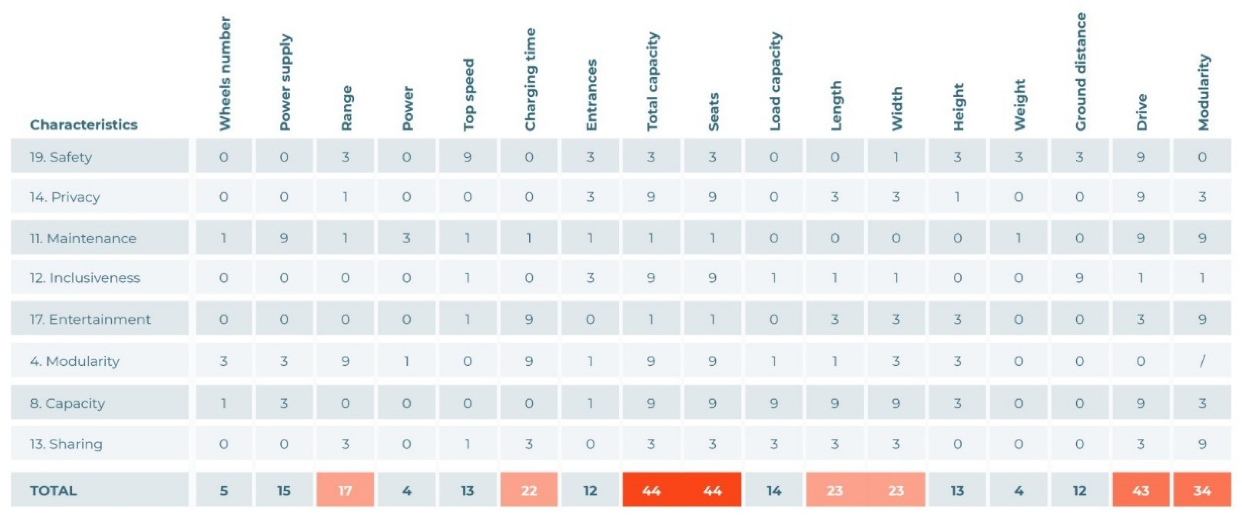
4.2. Technical Requirements

After evaluating the competitors through benchmarking, a draft idea was developed for the product, establishing its main characteristics and the desired features to be included in the final product. The optimal measures were established by placing proposed the vehicle into an intermediate sizing category. The defined dimensions for the bus are a length of 7000 mm, a width of 2500 mm, a height of 3000 mm, and a wheelbase of 3700 mm.
As evidenced by the research and matrices, we decided to adopt solutions based on the electrical power. As far as the choice of the motor is concerned, the choice fell on the rear single engine. This technology, although it requires more space for the chassis, was found to be widely present already on the current market and, therefore, safer and more reliable. The advantages related to the greater lightness and the higher obtainable performance should also be mentioned. Similar reasoning was also applied for the choice of the batteries. As for the batteries, the purpose of this paper is to hypothesize the size of the battery modules, their overall capacity (kWh) and respective range (Km/h), and their placement on the chassis. As can be seen from Figure 5, in the case of the Mercedes e-Citaro (Figure 5a) and Equipmake EBus (Figure 5b), currently, the area of the chassis most frequently used for the battery’s placement appears to be the rear of the vehicle. Before determining the sizing of the batteries according to the space available in the rear, it is necessary to assume the space occupied by the electric motor and inverter on the chassis. In the case of this project, the use of an electric motor from the Equipmake company was assumed (Figure 6a), specifically the AMP-200 model, as shown in Figure 6b. This model features an integrated gearbox design that is capable of providing a maximum power of 200 kW, with dimensions of 318 mm in diameter and 247 mm in length. To complete the powertrain, an inverter, the HPI-450 (Figure 6b), can be attached directly to the outside of the motor casing. It is also necessary to leave sufficient space for the cabling, cooling, and anchoring structure of the chassis, leaving the remaining space for the insertion of the batteries (Figure 7). An area of approximately 950 × 700 mm was assumed for the powertrain and 950 × 1500 mm for the batteries. The same battery modules as those used in the Tesla Model S were chosen, consisting of 444 Panasonic 18,650 B NCR cells with a total capacity of 5.3 kWh and dimensions of 685 × 300 × 75 mm [19,20]. Taking into consideration the increase in the final volume of the entire power system due to the presence of not only the modules but also the containment boxes and electrical components, such as wiring, cell connectors, and cell supervision circuitry [21], it is possible to assume the presence of 20 battery modules divided and organized into 4 packages of 5 modules for a total capacity of 106 kWh, as shown in Figure 7. An additional 10 battery modules can be placed behind the rear wheels (5 on the left and 5 on the right), reaching a total capacity of 159 kWh (Figure 8). As reported in the study reported in [22], a variable level of consumption, depending on the different conditions, ranging between 2.4 kWh/km and 4.6 kWh/km is calculated for city e-buses. These data allow us to calculate, in our case, a range of autonomy between 73 km and 38 km, further delineating the non-perfect system condition referred to in this paper. While, in regards of the level of driving autonomy, the level currently obtainable today is a level 2 [23], it can be estimated that there will be a considerable number of driverless cars on the roads (meaning level 3 and higher) by 2030. The software and the hardware requirements necessary to render the operation possible are as follows: algorithms; connectivity and GPS; LiDAR and RADAR for the recognition of distances and the geometry of the surrounding environment; cameras to recognize objects and subjects present in the environment; and ultrasonic sensors to identify obstacles in proximity to the vehicle [24]. The only major limitation of level 4 is “Geofencing” [25], which is the characteristic of having to submit to predefined paths or tracks, thus partially limiting the freedom and flexibility of the movement of the vehicles that use it. In this project, autonomous driving is exploited by both the minibus and the MBS module. In the first case, the minibus can cover the path of the various possible lines available, while in the case of the module, it is possible for it to reach and intercept a bus with a low battery, recharge it, and then return to an MBS charging station.

4.3. Other Auxiliaries

The electric bus is not complete without an HVAC system, a lighting system, and other auxiliaries, such as battery cooling, an air compressor, steering pump, and other elements. To provide a more in-depth discussion of the abovementioned elements is beyond the scope of this project; however, it must be said that the positioning of the HVAC system is thought to be roof-mounted, as in the case of a diesel city bus. This solution is also currently being implemented for electric buses [26], with compatible resistance heaters placed on the sides of the bus and a rooftop unit for cooling, as shown in Figure 9 below.

4.4. SDE

The “Stylistic Design Engineering (SDE)” [18] (or the Ramacciotti method) is a key step of the IDeS methodology. Tt aims to deepen our understanding of the above-mentioned topics while focusing on improving the design technologies and methodologies, such as the quality function deployment method (QFD), benchmarking (BM), and top-flop analysis (TFA), with a towards the development new innovative products from both a technological and stylistic point of view. The main steps of the SDE method include the following: an analysis of the stylistic trends currently used for the products already on the market in order to identify specific shapes and colours for each style; sketching the combination of traits obtained from the first step to create a first draft of the product (Figure 10); defining the dimensions of the product through 2D modelling software (e.g., AutoCAD); modelling using 3D modelling software (e.g., Creo PTC); and rendering through rendering software (e.g., Keyshot).
The SDE can systematize the design process of innovative products while reducing their costs. Designers can achieve these goals through digital sketches, 2D and 3D CAD, augmented reality, additive manufacturing, QFD, TRIZ, etc. The are all tools that, from the perspective of Industry 4.0, can benefit the design process.
Similar techniques include the SDS (semantic differential scale) [27,28] and the Kansei method [29], which is based on the evaluation of the different concepts and alternatives to select the one that is most appropriate for the target and target market.

5. Results

The final layout of the minibus is shown below with the aim of creating an innovative electric minibus by responding to the needs of the future. In a future where private means will decline in favor of an increase in the use of public transport and sharing systems, privacy may be lacking. The aim is to obtain private spaces in a typically public environment that can be used by the user as they see fit in order to simply relax or to optimize the travel time while working. Therefore, one of the key points was to obtain the maximum number of seats in relation to passengers’ comfort and the relatively small size of the vehicle. In addition, the mobile battery system (MBS) adopted can reduce the vehicle’s downtime as much as possible so that it can perform its service as a public transport vehicle.

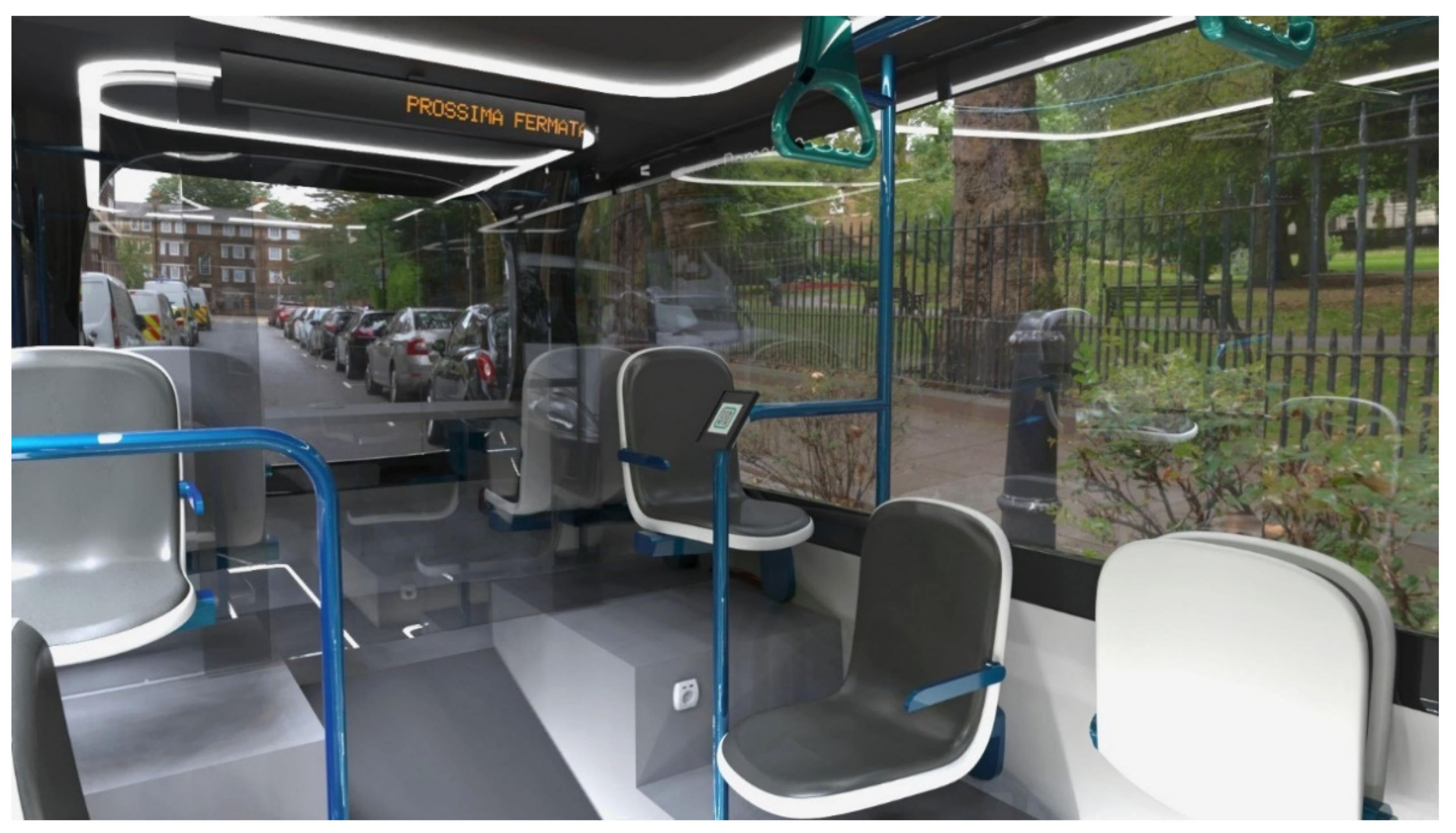
5.1. Interior Layout

The layout and organization of the minibus’s interior are based on the human dimension, ranging from ergonomic seats to private areas. The aim is to obtain the maximum number of seats in relation to the passengers’ comfort and the relatively small size of the vehicle. The minibus is designed with the total space divided into three parts (Figure 11): the relaxation space, the common space, and the office space. The public space, being the central, allows for different travel experiences on its sides. This management of the environment is enabled through the use of sliding electrochromic glass panels that provide access to the private areas located at both ends of the bus. The public area, accessible through the main and only entrance, is equipped with eight fixed seats and a reclined one in order to create room for disabled passengers, as well as a system of poles that support four handles for standing passengers. The rear part of the minibus is occupied by a relaxation area, where three seats (of which the central seat can be reclined to allow disabled people to use the service) are turned inwards and are equipped at the front with an object holder so as to allow the user to avoid carrying weighty items and to enjoy the journey. The head of the bus is instead occupied by a work area. The user who wishes to optimize the time he/she spends on public transport in order to work, study, or read can book this space, which is equipped with two seats and a table. Both private areas are bookable and can be accessed by scanning a QR code on the designated device located at the entrance of the public area. Once inside, the users can adjust the opacity of the glass due to its the electrochromic technology [30] and thus personalize their travel experience by regulating the desired level of privacy. The total number of seats amounts to 18, of which 2 are reclining and 4 are standing.
A 3D model of the body was created with Autodesk Alias, which allowed us to perform meticulous work in defining the dimensions and the design of the minibus (Figure 12) and its mobile battery system (Figure 13). The body of the minibus appears as symmetrical, except for the front and rear lights. A division of the bodies was hypothesized, which is fundamental for the production and maintenance phase of the bus but also enables the outlining of the spaces used for the design of several different liveries. The door is positioned centrally on the side panel, and uprights are positioned internally to support the glass structure under the pressure of the roof. The interior of the minibus is enriched with the details necessary for a bus that is designed to be on the road by 2040. An LED light pathway is positioned on the floor to guide passengers towards the private areas in the hours with poor lighting, and the course of these lights is mimicked on the ceiling (Figure 14), as if it were mirrored. Further services include the LED panels positioned in the public area that communicate the various stops to the user, the QR-code-scanning devices for booking private areas, and power sockets for recharging electronic devices. A rendering of the minibus is shown in Figure 15, placing the vehicle in a city environment.

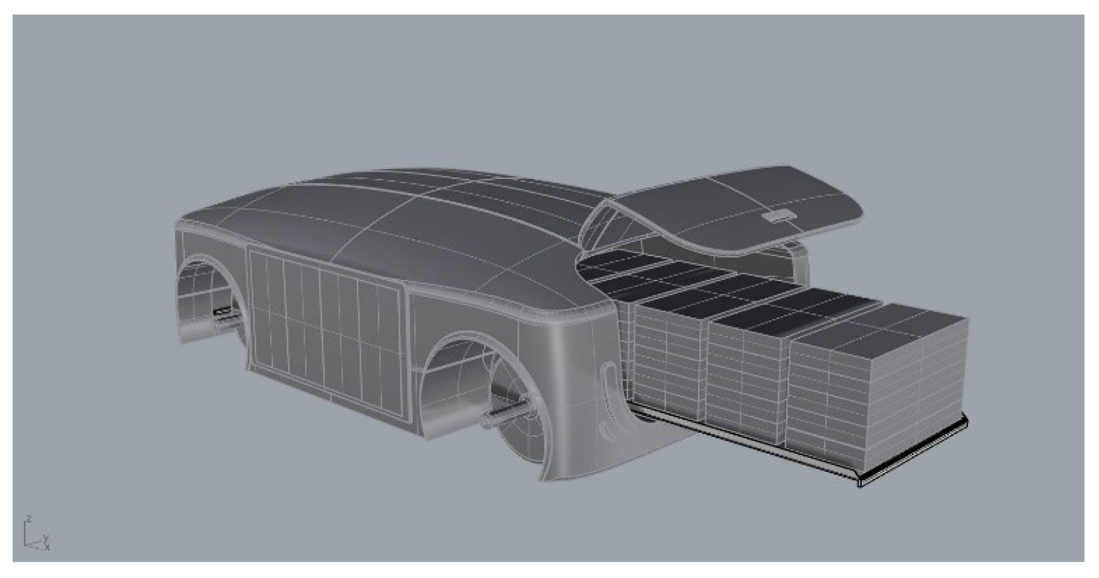
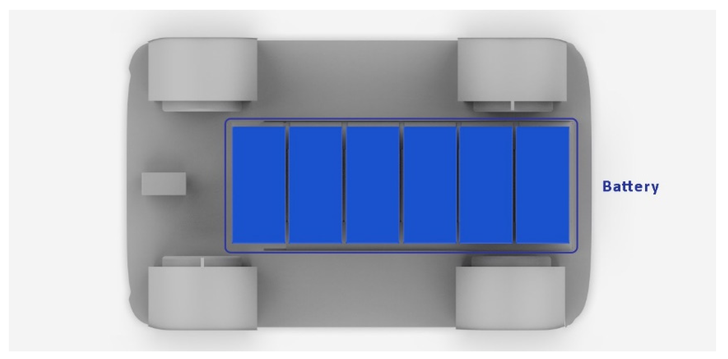
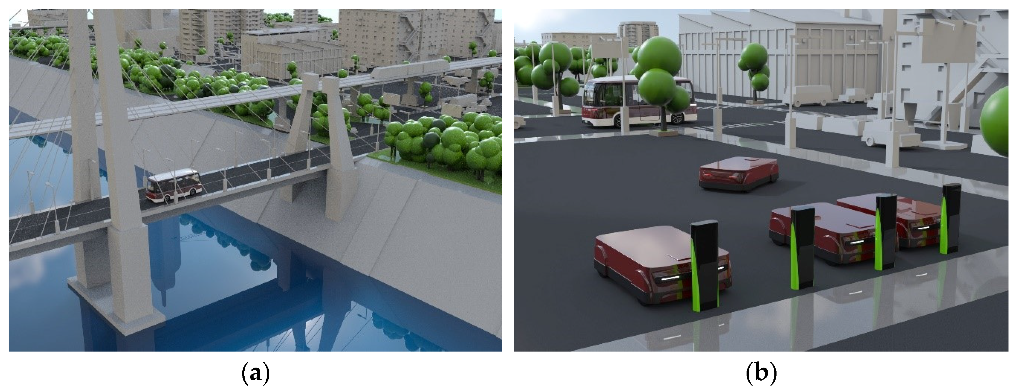
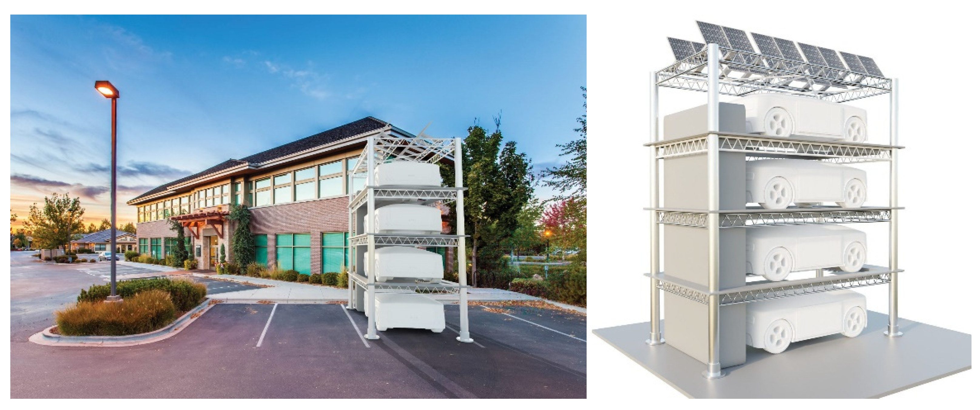
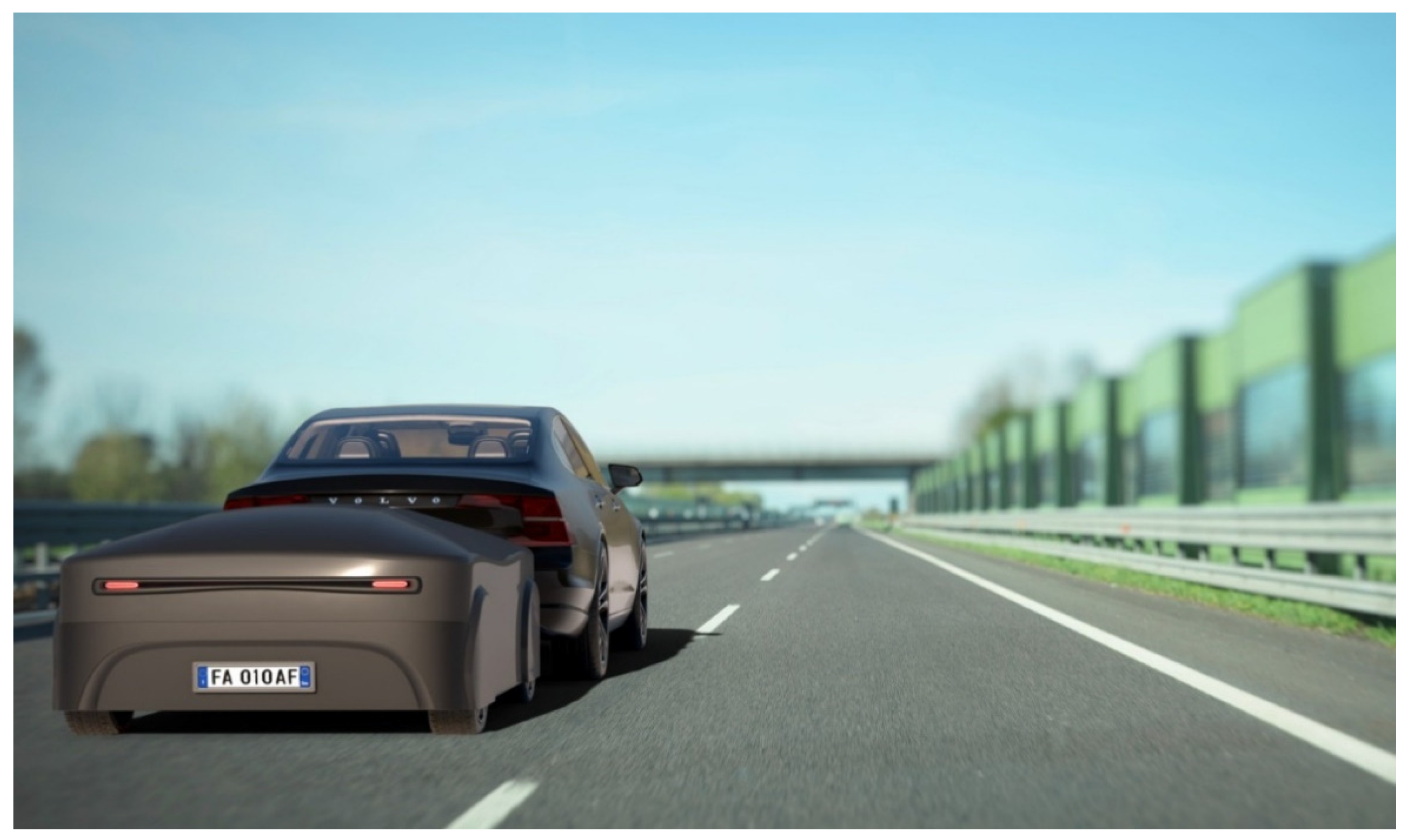
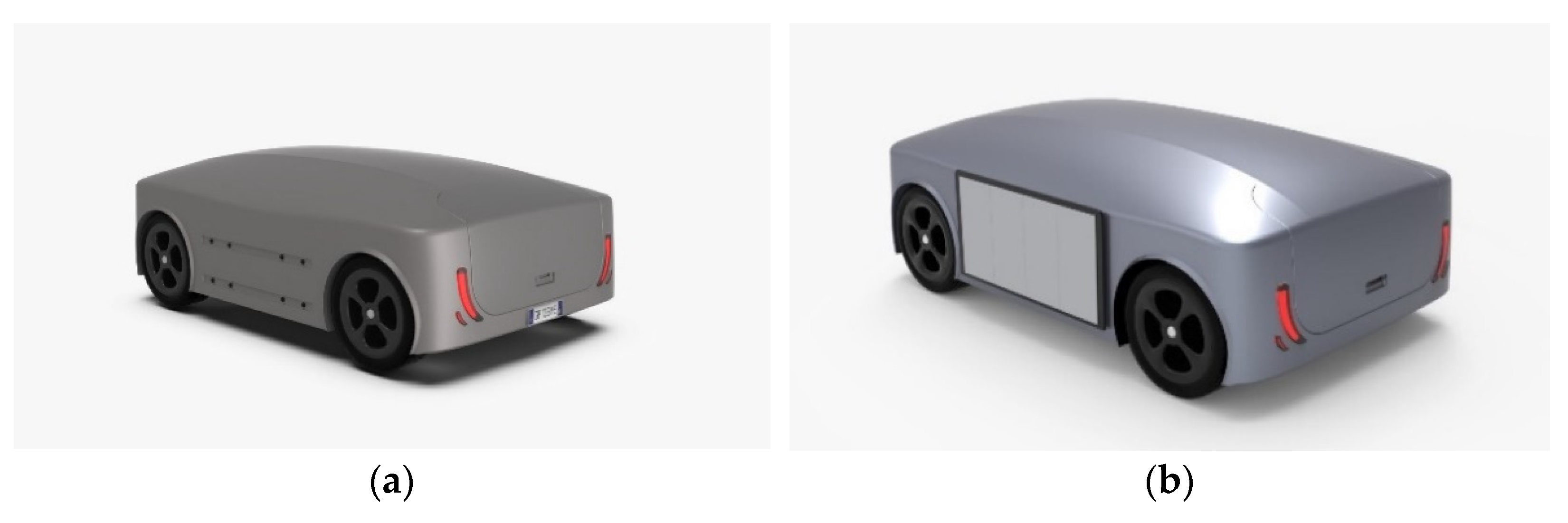
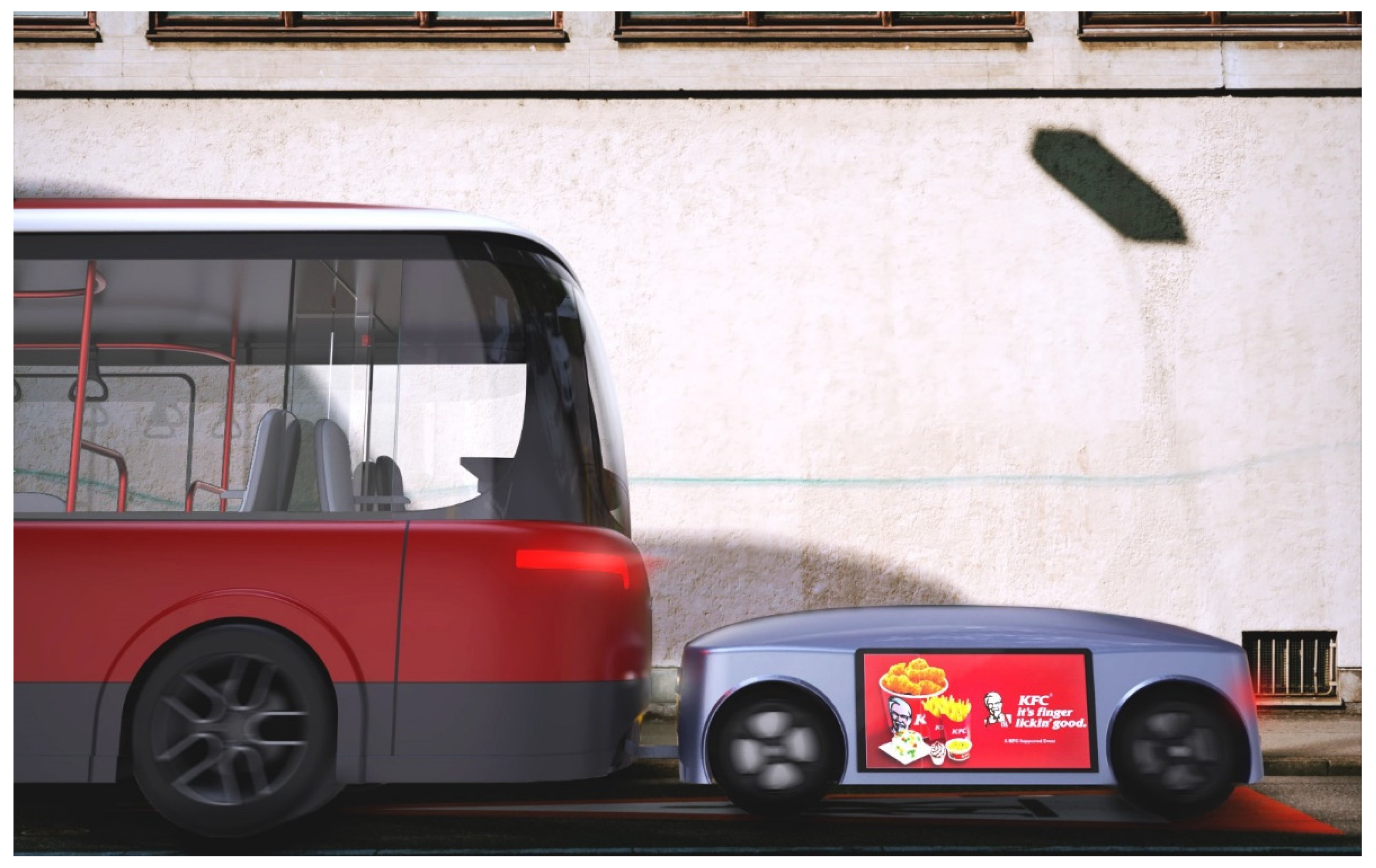
5.2. MBS (Mobile Battery System)

In the near urban future, one of the main problems of electric vehicles governed by complex algorithms and systems will be the range between charges [31]. The problem of electricity in regard to means of transport arises precisely in the recharging stage, which often requires prolonged times. In the case of a bus, the charging times at a dedicated station interrupt the transport service, which could ideally be extended, guaranteeing the vehicle’s continuous availability. Solutions to the electric system that do not interrupt the service include the construction of expensive and invasive infrastructures. More technologies that could avoid these complications are being studied and developed, such as contactless power transfer (CPT) systems [32], representing the first possible on-road charging solution. The MBS system proposed here compensates for the abovementioned defects as an innovative on-the-go charging system, represented in Figure 16a,b. Inspired by the in-flight refueling of aircrafts, it functions as a “power bank” on wheels and aims to fill the gaps in any imperfect system, providing urban (and eventually non-urban) vehicles with support to avoid the need stop to recharge their electric batteries. This means that infrastructures that are extended along the entire bus path will not be necessary due to the creation of a charging station outside the path for the modules.
The on-the-go charging system, therefore, consists of a module set up on the frame of a segment-A car. Its design follows the stylistic decisions made for the minibus and, therefore, the shape characteristics of the main surfaces are similar. The coupling system between the two electric vehicles is based on a technology which derives from an existing design of an innovative towbar: the Semcon Automatic Trailer Connection, which connects itself to the trailer automatically. Unlike the minibus, in the case of the MBS, motors directly mounted inside the wheels were chosen so as to leave more space on the chassis for the positioning of the batteries. In this case, the same batteries as those in the minibus (the same as those in the Tesla Model S) were used, and the same number of modules were used for a total capacity of 159kWh (Figure 17).
The following storyboard (Figure 18, Figure 19 and Figure 20) explains the functioning of the charging system in motion during its main phases.
When a minibus finds itself to have a low battery level (Figure 18a), which would not allow it to complete the day without stopping, a signal/request is sent to the system.
The system can identify the position of the minibus and select a module at the nearest station so that the module (Figure 18b) will independently intercept the minibus at a stop along its route (Figure 19a).
It is expected that docking will take place within the time during which the bus stops, with audible feedback transmitted to signal any danger (Figure 19b).
In this way, the vehicle is recharged on the go without the need for a stop (Figure 20a).
The time during which the module remains connected to the minibus for charging varies depending on how long the minibus has left to complete the day.
If, for example, the minibus is in a 10% state of charge and a range of only 20% would be required to complete the day, the module will only remain connected for as long as is required to achieve the desired charge.
Once the charging is complete, the module returns to its own charging point (Figure 20b).
The profound optimization of the meeting and docking point system will be necessary, monitoring the movement of the vehicles that need to be recharged and activated at the right time. There will be no need for large infrastructure, and this will guarantee a reduction in the costs and the optimization of the recharging times.

6. Conclusions and Future Development

In conclusion, following the initial research, a design scope was identified for a hypothetical future in which the decrease in private vehicles will lead to a significant increase in urban sharing and the emergence of new needs. At the same time, a number of shortcomings of the less-than-perfect urban system were considered, revealing design possibilities that are inherent in topics such as autonomous driving, vehicle electrification, and the creation of new types of e-bus charging infrastructure. The project goals were achieved through the redesign of the minibus’s internal layout and the development of the MBS mobile charging module. As far as the minibus is concerned, two private areas, located at the ends of the vehicle and accessible after booking via APP, were demarcated, which also helped us to establish a privacy zone through the use of electrochromic glass. These areas, which are also characterized by the presence of a ramp to ensure access, even for people with disabilities, are intended for a target audience seeking a useful space so as to optimize the time spent on the vehicle or for people who require a more isolated space in contrast to the rest of the vehicle. As for the mobile battery system (MBS), that is, a battery module capable of autonomously reaching a mini-bus in need of charging, the aim is to propose a solution for charging on the move, eliminating the need to stop the bus in the case of a low battery, thus extending its autonomy in order to guarantee service throughout the day. However, the proposed system has some clear limitations. The construction of the storage and recharging infrastructure for the modules and the development and maintenance of the modules themselves impose a cost hurdle that may erode the economic viability of the system. In this regard, we anticipate (Figure 21) the possibility of developing a system of vertical parking facilities that will ensure the recharging of multiple MBS at the same time. The structure will be developed to be as unobtrusive as possible, even within an urban context, and it will also be possible to install Co2 purifiers on the roof, as well as solar panels to power the parking structure’s signage. These will be placed at strategic points in the cities to ensure the optimal use of the modules for charging by electric vehicles. There are also plans to include plants to mimic the vertical forest concept and render the structure even more integrated into the urban context. In addition, in this paper, no in-depth studies were conducted on the communication system between the MBS module and the mini-bus, an aspect that is certainly central to the optimal management of both the movement of the modules within the city and the planning of the precise timespan during which module and bus remain connected for charging. It is, therefore, necessary to consider these aspects in any related future projects. The versatility and possible deployment of this system, however, offers the possibility of creating a number of additional interesting future hypotheses, which will be only briefly outlined below. One of these could be the design of adapters or complementary systems to be installed in other vehicles, such as other buses or electric cars. Alternatively, we can hypothesize the direct adoption of this technology by the manufacturers themselves. The flexibility of the technology is thus evident, which also allows its use to be expanded to a suburban context, proving particularly useful for private vehicles that require long commutes (Figure 22). The MBS module has additional potential; being a mobile platform, it can accommodate LED screens mounted directly on the sides (Figure 23) to project advertisements and commercials (Figure 24). Nowadays, it is the bus that is used for advertising purposes, tarnishing its overall image. By delegating the advertising role to the MBS, the image of the minibus is preserved by obtaining a secondary service for companies or those who are willing to pay for the broadcasting of their advertisements along an urban route.

Author Contributions

L.F. reviewed the group work throughout all stages of development and gave the overall approval. G.D. reviewed the group work throughout all stages of development. G.G. was in charge of the general project review, management of the paper’s implementation and project refinement G.P., M.P., and E.Z. handled the development of the project from the initial stages to its conclusion. All authors have read and agreed to the published version of the manuscript.

Funding

This research received no external funding.

Data Availability Statement

Not applicable.

Acknowledgments

The materials and machines used for the development of the prototypal phase were provided by the DIN (Department of Industrial Engineering) at Alma Mater Studiorum, Università di Bologna.

Conflicts of Interest

The authors declare no conflict of interest.

References

  1. European Environment Agency. A Closer Look at Urban Transport: TERM 2013: Transport Indicators Tracking Progress Towards Environmental Targets in Europe; Publications Office of the European Union: Luxembourg, 2013. [Google Scholar]
  2. Miskolczi, M.; Földes, D.; Munkácsy, A.; Jászberényi, M. Urban mobility scenarios until the 2030s. Sustain. Cities Soc. 2021, 72, 103029. [Google Scholar] [CrossRef]
  3. Enoch, M.P.; Cross, R.; Potter, N.; Davidson, C.; Taylor, S.; Brown, R.; Huang, H.; Parsons, J.; Tucker, S.; Wynne, E.; et al. Future local passenger transport system scenarios and implications for policy and practice. Transp. Policy 2020, 90, 52–67. [Google Scholar] [CrossRef]
  4. Rüdisüli, M.; Bach, C.; Bauer, C.; Beloin-Saint-Pierre, D.; Elber, U.; Georges, G.; Limpach, R.; Pareschi, G.; Kannan, R.; Teske, S.L. Prospective life-cycle assessment of greenhouse gas emissions of electricity-based mobility options. Appl. Energy 2022, 306, 118065. [Google Scholar] [CrossRef]
  5. Manzolli, J.A.; Trovão, J.P.; Antunes, C.H. A review of electric bus vehicles research topics–Methods and trends. Renew. Sustain. Energy Rev. 2022, 159, 112211. [Google Scholar] [CrossRef]
  6. Vilaça, M.; Santos, G.; Oliveira, M.S.; Coelho, M.C.; Correia, G.H. Life cycle assessment of shared and private use of automated and electric vehicles on interurban mobility. Appl. Energy 2022, 310, 118589. [Google Scholar] [CrossRef]
  7. Silva, Ó.; Cordera, R.; González-González, E.; Nogués, S. Environmental impacts of autonomous vehicles: A review of the scientific literature. Sci. Total Environ. 2022, 830, 154615. [Google Scholar] [CrossRef]
  8. Jefferies, D.; Göhlich, D. A comprehensive TCO evaluation method for electric bus systems based on discrete-event simulation including bus scheduling and charging infrastructure optimisation. World Electr. Veh. J. 2020, 11, 56. [Google Scholar] [CrossRef]
  9. Palomino, A.; Parvania, M. Advanced charging infrastructure for enabling electrified transportation. Electr. J. 2019, 32, 21–26. [Google Scholar] [CrossRef]
  10. He, Y.; Song, Z.; Liu, Z. Fast-charging station deployment for battery electric bus systems considering electricity demand charges. Sustain. Cities Soc. 2019, 48, 101530. [Google Scholar] [CrossRef] [Green Version]
  11. Guschinsky, N.; Kovalyov, M.Y.; Rozin, B.; Brauner, N. Fleet and charging infrastructure decisions for fast-charging city electric bus service. Comput. Oper. Res. 2021, 135, 105449. [Google Scholar] [CrossRef]
  12. He, Y.; Liu, Z.; Song, Z. Optimal charging scheduling and management for a fast-charging battery electric bus system. Transp. Res. Part E: Logist. Transp. Rev. 2020, 142, 102056. [Google Scholar] [CrossRef]
  13. Ke, B.R.; Lin, Y.H.; Chen, H.Z.; Fang, S.C. Battery charging and discharging scheduling with demand response for an electric bus public transportation system. Sustain. Energy Technol. Assess. 2020, 40, 100741. [Google Scholar] [CrossRef]
  14. Moon, J.; Kim, Y.J.; Cheong, T.; Song, S.H. Locating battery swapping stations for a smart e-bus system. Sustainability 2020, 12, 1142. [Google Scholar] [CrossRef] [Green Version]
  15. Kumar, T.; Kumar, N.; Thakur, T.; Nema, S. Charge scheduling framework with multiaggregator collaboration for direct charging and battery swapping station in a coupled distribution-transportation network. Int. J. Energy Res. 2022, 46, 11139–11162. [Google Scholar] [CrossRef]
  16. Mohanty, P.K.; Jena, P.; Padhy, N.P. Integration of Battery Swapping Station into Microgrid: A Review. In Proceedings of the 2022 International Conference on Intelligent Controller and Computing for Smart Power (ICICCSP), Hyderabad, India, 21–23 July 2022; pp. 1–5. [Google Scholar]
  17. Ginting, R.; Ishak, A.; Malik, A.F.; Satrio, M.R. Product development with quality function deployment (QFD): A literature review. IOP Conf. Ser. Mater. Sci. Eng. 2020, 1003, 012022. [Google Scholar] [CrossRef]
  18. Frizziero, L.; Donnici, G.; Liverani, A.; Alessandri, G.; Menozzi, G.C.; Varotti, E. Developing innovative crutch using IDeS (industrial design structure) methodology. Appl. Sci. 2019, 9, 5032. [Google Scholar] [CrossRef] [Green Version]
  19. Kuipers, M.; Meier, S.; Hust, F.; Sauer, D.U. An In-Depth View into the Tesla Model Smodule Part Two: Module Characterization and Comparison to Other State of the Art EV Battery Systems; No. FZJ-2017-02840; Helmholtz-Institut Münster Ionenleiter für Energiespeicher: Münster, Germany, 2017. [Google Scholar]
  20. Motors, T. Vehicle Battery Pack Ballistic Shield. U.S. Patent 8286743, 5 December 2012. Available online: http://www.patentlens.net/patentlens/patents.html?patnums=US_8286743 (accessed on 12 September 2022).
  21. Arora, S.; Kapoor, A. Mechanical Design and Packaging of Battery Packs for Electric Vehicles. In Behaviour of Lithium-ion Batteries in Electric Vehicles; Springer: Cham, Switzerland, 2018. [Google Scholar] [CrossRef]
  22. Basma, H.; Mansour, C.; Haddad, M.; Nemer, M.; Stabat, P. Energy consumption and battery sizing for different types of electric bus service. Energy 2022, 239, 122454. [Google Scholar] [CrossRef]
  23. Barabás, I.; Todoruţ, A.; Cordoş, N.; Molea, A. Current challenges in autonomous driving. IOP Conf. Ser. Mater. Sci. Eng. 2017, 252, 012096. [Google Scholar] [CrossRef]
  24. Antony, M.M.; Whenish, R. Advanced Driver Assistance Systems (ADAS). In Automotive Embedded Systems; Kathiresh, M., Neelaveni, R., Eds.; EAI/Springer Innovations in Communication and Computing; Springer: Cham, Switzerland, 2021. [Google Scholar]
  25. Sankalprajan, P.; Muppidi, A.J.; Pagala, P.S. Analysis of Computational Need of 2D-SLAM Algorithms for Unmanned Ground Vehicle. In Proceedings of the 2020 4th International Conference on Intelligent Computing and Control Systems (ICICCS), Madurai, India, 13–15 May 2020; pp. 230–235. [Google Scholar]
  26. Göhlich, D.; Fay, T.; Jefferies, D.; Lauth, E.; Kunith, A.; Zhang, X. Design of urban electric bus systems. Des. Sci. 2018, 4, E15. [Google Scholar] [CrossRef]
  27. Lu, X.L.; Chen, C.L. The Study on Visual Style Preferences of Automotive Printing Interior Board in Mainland China. In Proceedings of the 2018 International Conference on Mechanical, Electronic and Information Technology (ICMEIT 2018), Qingdao, China, 30–31 March 2018. [Google Scholar]
  28. Matsuoka, K.; Maedomari, H.; Sato, K.; Terauchi, F. Factorial Structure of Evaluations of Automotive Interior Material Texture. J. Sci. Des. 2019, 3, 1_53–1_60. [Google Scholar]
  29. Lai, X.; Zhang, S.; Mao, N.; Liu, J.; Chen, Q. Kansei engineering for new energy vehicle exterior design: An internet big data mining approach. Comput. Ind. Eng. 2022, 165, 107913. [Google Scholar] [CrossRef]
  30. Rauh, R.D. Electrochromic windows: An overview. Electrochim. Acta 1999, 44, 3165–3176. [Google Scholar] [CrossRef]
  31. Kadav, P.; Asher, Z.D. Improving the Range of Electric Vehicles. In Proceedings of the 2019 Electric Vehicles International Conference (EV), Bucharest, Romania, 3–4 October 2019; pp. 1–5. [Google Scholar] [CrossRef]
  32. Chopra, S.; Bauer, P. Driving Range Extension of EV With On-Road Contactless Power Transfer—A Case Study. IEEE Trans. Ind. Electron. 2013, 60, 329–338. [Google Scholar] [CrossRef]
Figure 1. Relative importance matrix.
Inventions 08 00001 g001
Figure 2. Independence matrix.
Inventions 08 00001 g002
Figure 3. Benchmark.
Inventions 08 00001 g003
Figure 4. Innovation Table.
Inventions 08 00001 g004
Figure 5. (a) Battery placement in the Mercedes Citaro. (b) Battery placement in the Equipmake.
Inventions 08 00001 g005
Figure 6. (a) Electric motor dimensions in the Equipmake. (b) AMP-200 electric motor and HPI-450 inverter.
Inventions 08 00001 g006
Figure 7. Battery and powertrain placement.
Inventions 08 00001 g007
Figure 8. Chassis and battery placement.
Inventions 08 00001 g008
Figure 9. Placement of an HVAC system.
Inventions 08 00001 g009
Figure 10. Bus sketches.
Inventions 08 00001 g010
Figure 11. Interior layout.
Inventions 08 00001 g011
Figure 12. Minibus 3D model.
Inventions 08 00001 g012
Figure 13. Mobile battery system 3D model.
Inventions 08 00001 g013
Figure 14. Details of the minibus interior.
Inventions 08 00001 g014
Figure 15. Rendering of the minibus in a city environment.
Inventions 08 00001 g015
Figure 16. (a) Module front. (b) Module rear.
Inventions 08 00001 g016
Figure 17. Module battery placement.
Inventions 08 00001 g017
Figure 18. (a) Minibus out of battery. (b) Module activation and mutual communication.
Inventions 08 00001 g018
Figure 19. (a) Module approaching the minibus. (b) Docking with audible safety feedback.
Inventions 08 00001 g019
Figure 20. (a) Charging on the go. (b) Detachment and arrival at the station/other vehicle.
Inventions 08 00001 g020
Figure 21. Recharge tower.
Inventions 08 00001 g021
Figure 22. MBS system in an extra-urban context.
Inventions 08 00001 g022
Figure 23. (a) Module without screen. (b) Module with screen.
Inventions 08 00001 g023
Figure 24. Commercials displayed on the MBS.
Inventions 08 00001 g024
Disclaimer/Publisher’s Note: The statements, opinions and data contained in all publications are solely those of the individual author(s) and contributor(s) and not of MDPI and/or the editor(s). MDPI and/or the editor(s) disclaim responsibility for any injury to people or property resulting from any ideas, methods, instructions or products referred to in the content.

