1. Introduction
Currently, about 40% of electricity produced in the world is consumed by induction motors, the number of which exceeds 300 million units [
1,
2]. They are mostly used in various industrial production processes, consuming up to 80% of electricity in this sector of the economy [
3,
4]. A significant share of that electricity is used by pumping systems, which consume about 22% of the mentioned amount [
5].
Such a wide distribution of induction motors can be explained by their high reliability and relatively low manufacturing cost [
6,
7]. At the same time, the operational reliability of induction motors in all sectors of the European economy is insufficient, as evidenced by the following: the annual cost of repairs and maintenance of these motors amounts to 8% of the annual cash flow of any branch of economic activity [
8]. Up to 4% of induction motors fail annually [
9]. The primary reason for such low operational reliability of these motors is external exposure to various factors on the part of the mains power supply and the peculiarities of working machines. This becomes especially relevant with the increasing use of alternative energy sources for power supply from local networks (such factors include changes in wind speed, solar insolation, etc.) [
10,
11,
12]. The thermal ageing of insulation and reduced supply voltage at the terminals of induction motors have a significant impact on their operational reliability [
13,
14,
15,
16,
17,
18,
19].
It is known that even a slight decrease in the quality of the supply voltage leads to negative consequences associated with the deterioration of insulation and a decrease in the energy efficiency and power of induction motors [
20]. When the voltage in the network deviates from the nominal value, the active power on the motor shaft remains almost constant, while the active power loss changes [
21,
22]. This causes a change in the heating of the induction motor and, as a consequence, a change in the rate of the thermal wear of its insulation. Thermal wear is one of the main factors influencing the deterioration of insulation [
23,
24,
25].
For many induction motors, energy-saving control systems are currently used. One of the regulating factors of these systems is the supply voltage, which is usually reduced in relation to the nominal value. Many studies are concerned with this problem, and it has been analyzed in sufficient detail in review works [
26,
27,
28,
29,
30]. The number of publications on this topic continues to increase, which indicates the urgency of the issue. In [
28], energy-saving control methods for induction motors are divided into the following groups: (1) methods concerning the condition of the motor; (2) methods based on the model of power loss in the motor; and (3) methods using direct optimization.
The first group includes methods in which the regulation of the speed of electric motors is performed by applying voltage or frequency or both [
26,
27,
28,
29,
30]. Direct or indirect control of the current (or the square of the current strength) of the stator winding is performed. When its value is minimal at the given speed of the shaft, it is believed that the power consumption of the motor will also be minimal. However, only variable power losses depend on the current of the stator winding; constant power losses are independent and are determined by the magnetic flux and the speed of rotation. Therefore, the disadvantages of this group of methods include the fact that the mains deviation, the load of the motor, the mechanical characteristics of the working machine, the heating of its active parts, and the rate of thermal wear of the motor insulation are not taken into account.
The second group of methods is based on the dependence of the combined power loss on the magnetizing current [
26,
27,
28,
29,
30]. By finding the first derivative of this dependence and setting it to zero, an equation for controlling the speed of the motor is obtained. The methods differ by types of dependencies and control algorithms, and the load of the motor is usually taken into account by considering the current consumption. The disadvantages of these methods include significant linearization of the motor parameters and neglecting the mains deviations. Further, the mechanical characteristics of the working machine and the thermal wear of the motor insulation are not taken into account.
The third group includes methods using artificial neural networks or fuzzy logic devices for the optimization of power consumption [
26,
27,
28,
29,
30]. These methods include the approximation of non-linear dependence, for example, between its magnetizing current and torque, speed, and power loss. The optimum value of the magnetizing current is then determined. The disadvantages of these methods include the relatively long optimization time and neglecting the mains deviation. The mechanical characteristics of the working machine and the thermal wear of the motor insulation are not taken into account.
In [
31], a method for increasing the efficiency of the induction motor is proposed, provided that the temperature of its stator winding increases. It is proposed to compensate the voltage drop in the stator winding, which is caused by additional heating. For this purpose, voltage is increased in direct proportion to the compensation factor. This voltage compensation does not take into account its phase, and therefore the current in its stator windings increases. This results in its overheating and accelerated wear of insulation.
In [
32], it is proposed to run the induction motor with minimum power loss by adjusting the voltage. For this purpose, the author obtained a voltage dependency of the motor, for which the power loss is minimal. However, mechanical losses in electric motors that may vary due to even minor bearing damage are not taken into account. Further, the author disregards the fact that the motor slip is a function of the applied voltage and load of the electric motor. The mentioned deficiencies will result in reduced voltage. This will cause motor overload, which will lead to the overheating and wear of the stator winding insulation.
In [
33], it is proposed to run the induction motor at minimum energy loss by adjusting the voltage. The authors developed the field-oriented control system of the motor speed that provides the motor phase currents control and the rotation speed of its shaft. These values are used to determine the voltage, under which the motor will consume a minimum of power under the given operating conditions. This method assumes that the parameters of the motor are constant. However, when the motor is running, these parameters change due to the magnetization reversal of the magnetic circuit and the heating of its active parts. Unless this is taken into account, the optimal voltage will be too low, which will cause motor overload and result in the overheating and accelerated wear of its insulation.
Thus, all of the mentioned methods of energy-saving control disregard the relationship between the voltage of the motor and the rate of its insulation wear, which results in its low operational reliability.
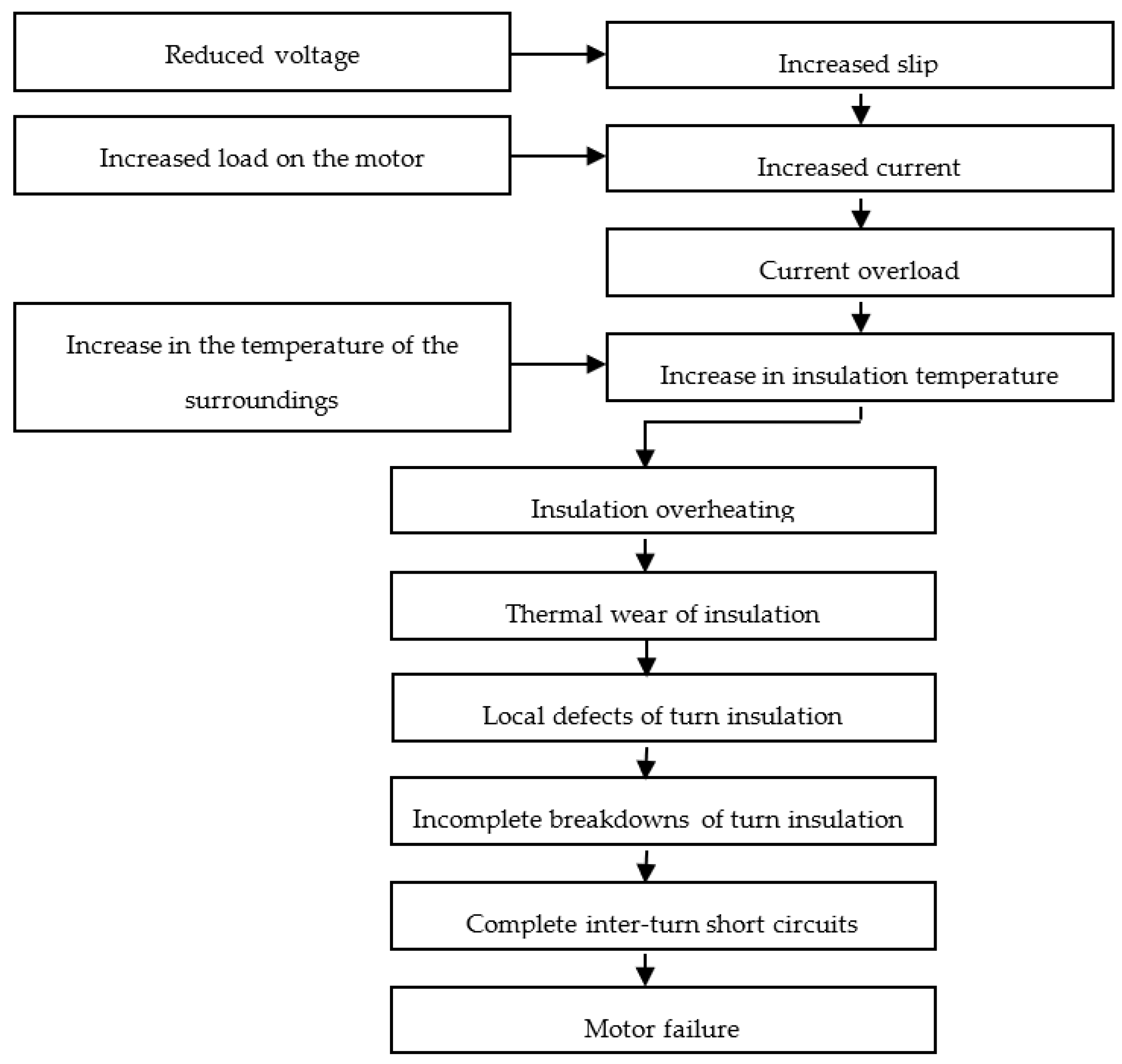
Let us consider the influence of voltage reduction on the speed of the insulation wear of the motor and its operational reliability based on [
6,
34,
35,
36,
37]. Reducing the voltage of running induction motors leads to an increase in their slip and, as a consequence, to an increase in current consumption and current overload. The latter causes vibration, high electrodynamic forces between the conductors of the winding, low resistance of the turn insulation, and overheating of the turn insulation, the ground insulation, and the core, resulting in its thermal wear and leading to local defects of the insulation in its slot and coil end parts. These defects cause incomplete breakdowns of the turn insulation, followed by complete inter-turn short circuits, which lead to motor failures.
At the same time, it is essential that the change in the load on the motor and the change in the temperature of the surroundings are considered. Increasing the load on the working machines leads to an increase in current consumption, overload of the motors, overheating of the turn insulation, its thermal wear, local defects of turn insulation, incomplete breakdowns, and eventually, to complete inter-turn short circuits and failures of the motor. The temperature of the surroundings rise, leading to the same consequences.
Thus, the influence of voltage reduction on the rate of the insulation wear of the motor and its operational reliability will be as follows (
Figure 1).
As follows from
Figure 1, the main manifestation of the unacceptable voltage reduction of induction motors is an increase in their heating, which leads to thermal wear of the insulation. The rate of thermal wear of the insulation is calculated as follows [
38,
39]:
where
ε—rate of thermal wear of insulation,
bas.h/h. (base hours per hour);
εn—nominal rate of thermal wear of insulation, bas.h/h.;
B—insulation class, K;
τ1n—nominal steady-state temperature excess of insulation, °C;
ϑsur.n—nominal temperature of the surroundings, °C;
τ1st—current steady-state temperature excess of insulation, °C;
ϑsur.—current temperature of the surroundings, °C.
Thus, the rate of thermal wear of insulation depends on the nominal rate of thermal wear of insulation εn, the parameter characterizing the insulation class, B, nominal steady-state temperature excess of insulation, τ1n, nominal temperature of the surroundings, ϑsur.n, current steady-state temperature excess of insulation, τ1st, and current temperature of the surroundings, ϑamb, that is ε = f (εn, B, τ1n, ϑsur.n, τ1st, ϑsur.). The values of εn, B, τ1n, ϑsur.n depend only on the design of the induction motor, the value of ϑsur. determines the effect of temperature of the surroundings on the rate of thermal wear of insulation, and the value of τ1st determines the influence of the operation mode on the rate of thermal wear of insulation, which is characterized by the load voltage, the load level, and the mechanical characteristics of the working machine. These factors affect the slip, power losses, and other performance indicators of the motor, causing changes in its thermal condition. The latter is characterized by changes in steady-state temperature excess of its winding, leading to a change in the rate of thermal wear of its insulation. Therefore, the purpose of the present work is to establish the resource-saving rule of the voltage regulation of the motor in energy-saving operation mode. To achieve the purpose of the study, the following problems must be solved:
To establish how the steady-state temperature excess of the stator insulation depends on the losses of active power in its structural components;
To find out how the active power losses in the structural components of the motor depend on the voltage and the load;
To establish the dependence between the current slip of the motor and the voltage, the load of the motor, and the type of mechanical characteristics of the working machine;
To perform analytical modelling of the dependence of the rate of thermal wear of insulation on voltage and load, taking into account the mechanical characteristics of the working machines.
3. Results and Discussion
3.1. Dependence of the Steady-State Temperature Excess of the Stator Insulation on the Active Power Losses in Its Structural Components
To establish this dependence, we apply the thermal equivalent circuit of the induction motor. There are two types of such circuits: two-element and multi-element, with different interpretations. The two-element thermal circuit implies that power losses take place in the copper and steel of the motor [
40]. It requires few data for determining the steady-state temperature excess of the stator winding, all of which are available. The calculations are performed quickly, but their accuracy is far from perfect. In addition, the results of calculations are applied for all electric motors of this type at the same load and voltage, not taking into account possible changes in their structural components caused by operation (deterioration of cooling conditions, malfunctions, etc.). The multi-element thermal circuit distributes the structural components of the motor into sections, and the power losses in motor units are distributed into separate components [
41,
42]. In this case, calculations have high accuracy, but are quite bulky and require a considerable amount of input data: geometrical data of the electric motor, characteristics of materials, boundary conditions, etc., which are not always available for a specific motor. Further, the results of the calculations are applied for all motors of this type at the same load and voltage, not taking into account possible changes in the structural components.
To avoid the above-mentioned disadvantages, it is necessary to get a new algorithm for determining the steady-state temperature excess of the stator winding, which will take into account the thermal condition of a particular motor and will have sufficient accuracy. To establish this dependence, let us consider the induction motor as a system of three bodies: (1) stator winding; (2) rotor winding; (3) steel (core, mechanical part, and housing) and assume that the heat capacity of the environment around the motor is equal to infinity and the temperature of the surroundings is nominal and constant (
Figure 2). This is sufficient for the analysis of the operational processes in it, more accurate than [
40], and does not require a large amount of output data as opposed to [
41,
42].
The diagram (
Figure 2) shows the following symbols:
C1, C2, C3—heat capacity of the respective bodies, J/°C;
τ1,τ2,τ3—excess temperature of the respective bodies over the temperature of the surroundings, °C;
P1, P2, P3—loss of active power in the respective bodies, W;
Λ12, Λ13, Λ23—thermal conductivity between the respective bodies, W/°C;
Λ—thermal conductivity between the third body and the surroundings, W/°C;
Csur—heat capacity of the surroundings, W/°C;
ϑsur—temperature of the surroundings, °C.
The system of heat balance equations for the circuit shown in
Figure 2 is as follows:
The solution of the system of Equation (2) for
τ1 in the steady-state mode of the operation of the motor (
τ1st) is as follows:
where
a—impact coefficient of losses
P1 on the heating of the stator insulation, °C/
W;
b—impact coefficient of losses P2 on the heating of the stator insulation, °C/W;
c—impact coefficient of losses P3 on the heating of the stator insulation, °C/W.
The coefficients obtained after solving (2) are equal to
where
Thus, the steady-state temperature excess depends on the coefficients of the impact of active power losses in the motor units on the heating of the stator insulation and is a function of these losses (P1, P2, P3).
In turn, coefficients
a, b, c represent a complex function of thermal conductivity. These coefficients allow avoiding thermal conductivity of the electric motor, in contrast to [
41,
42]. In order to determine these coefficients, the excess of the stator insulation temperature over the temperature of the surroundings was studied under short circuit and idling. Based on these parameters, a system of three equations was derived, each of which represents an Equation (3) for the tests of nominal load, short circuit, and idling. It is assumed that these coefficients are the same in all of these modes. The system of equations is as follows:
where
τ1n,
τ1sh,
τ1id—steady-state excess of the stator insulation temperature in experiments of nominal load, short circuit, and idling, respectively, °C;
P1n, P2n, P3n—loss of active power in the respective bodies in the nominal load test, W;
P1sh, P2sh, P3sh—loss of active power in the respective bodies in the short circuit test, W;
P1id, P2id, P3id—loss of active power in the respective bodies in the idling test, W.
In the short circuit test, the mechanical losses were equal to zero, and it was performed at nominal current in the stator insulation, so it is assumed that
P3sh ≈ 0, and
P1sh ≈ P1n and
P2sh ≈ P2n. In the idling test, the voltage at the motor terminals was nominal, and the slip was
s ≈ 0, so it is assumed that
P3id ≈ P3n and
P2id ≈ 0. Taking into account these assumptions, the system of Equation (6) with coefficients
a,
b,
c is solved as follows:
The obtained Equations (3) and (7) allow the calculation of the steady-state temperature excess of the induction motor at any rate of power loss in the bodies of its thermal equivalent circuit due to the impact of these losses on the heating of the stator winding. These coefficients are determined by standard operational tests (idling and short circuit) and allow identification of the thermal condition of a particular motor, taking into account the current condition of its active parts. This increases the accuracy of the proposed method, which distinguishes it from the ones proposed in [
40,
41,
42]. The value of the steady-state temperature excess, calculated according to the methods described in [
40,
41,
42], is applied for all motors of a certain type and size, and according to [
40,
41,
42], it does not matter whether the motor is new or has already been in operation for some time. However, while the motor is in service, changes may occur in its active parts (deterioration of cooling conditions, malfunctions, etc.), which will lead to changes in its thermal conductivity. The latter will cause a change in the steady-state temperature excess of the motor, which is not taken into account in [
40,
41,
42]. The method of determining the steady-state temperature excess, which is proposed in the present work, has no such deficiencies, which is conditioned by the added coefficients of the active power loss impact on the heating of the stator windings, which are experimentally determined for each electric motor, instead of using the nameplate data.
3.2. Dependence of Active Power Losses of the Motor on the Voltage and Load
Proceeding from (3), it is necessary to establish the dependence of power losses, which occur in the bodies of thermal equivalent circuit of the induction motor (
Figure 2), on the voltage taking into account the load of the motor. In [
43], such correlation is indicated, but it is assumed that the load is constant. In [
44], the correlation of losses is partially indicated without taking into account the change in the load. This correlation is described in [
20,
32], but only between two components, permanent and variable losses. Thus, the existing publications do not solve the problem in full.
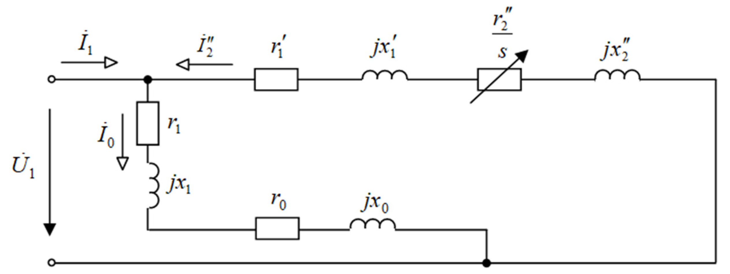
To establish this dependence, let us consider the L-shaped equivalent circuit of a three-phase induction motor shown in
Figure 3.
The diagram (
Figure 3) shows the following:
—complex of effective phase voltage;
—complex of effective phase current;
—complex of effective current in the load branch;
—complex of effective current in the magnetizing branch; s—slip of the motor;
,
,
,
,
,
,
—circuit parameters.
According to this circuit, the loss of active power in the first body of the thermal equivalent circuit can be represented as
At nominal voltage
U1n and nominal load (that is nominal slip
sn), Equation (8) will take the following form:
By dividing (8) by (9), we obtain:
where
—reduction of voltage coefficient.
The loss of active power in the second body of the thermal equivalent circuit can be represented as follows:
At nominal voltage
U1n and nominal load (that is nominal slip
sn), Equation (11) will take the following form:
By dividing (11) by (12), we obtain:
The loss of active power in the third body of the thermal equivalent circuit is calculated as follows:
At nominal voltage
U1n, equation (14) will take the following form:
By dividing (14) by (15), we obtain:
The derived Equations (10), (13) and (16) show the dependence of power losses, which occur in the bodies of the proposed thermal equivalent circuit (
Figure 2), on the voltage and load of the motor according to its L-shaped equivalent circuit. These equations allow the determination of constant and variable power losses divided into two parts, which, in contrast to [
20,
32], completely satisfy the conditions of the objective of the present study. Compared to [
43,
44], the above expressions take into account the operating mode of the motor more accurately. When the motor is controlled with voltage, the load can change, which will require clarification of the value of voltage. Mathematical models of power loss given in [
43,
44] do not take this into account and therefore lead to a lower optimum voltage. The latter causes the switching of the electric motor to the overload mode, its overheating, and acceleration of the thermal wear of its insulation. The mathematical model of power loss proposed in the present work is devoid of such deficiencies as it takes into account simultaneous changes of the voltage and the load of the motor. The mains deviation is taken into account through coefficient
ku, and the load of the motor —through the slip
s. The additional losses in electric motors are not taken into account; however, they amount to no more than 1% of the power consumed, so this disadvantage will not affect the results of calculations significantly.
Therefore, taking into account (10), (13), and (16), Equation (3) will take the following form:
3.3. Dependence of the Slip of the Motor on Voltage and Load
In Equation (17), the slip is the indicator of the operation mode of the motor, in addition to the multiplicity of the voltage, which also depends on the voltage. It is known that the slip of the induction motor at constant load depends on the square of the voltage [
45,
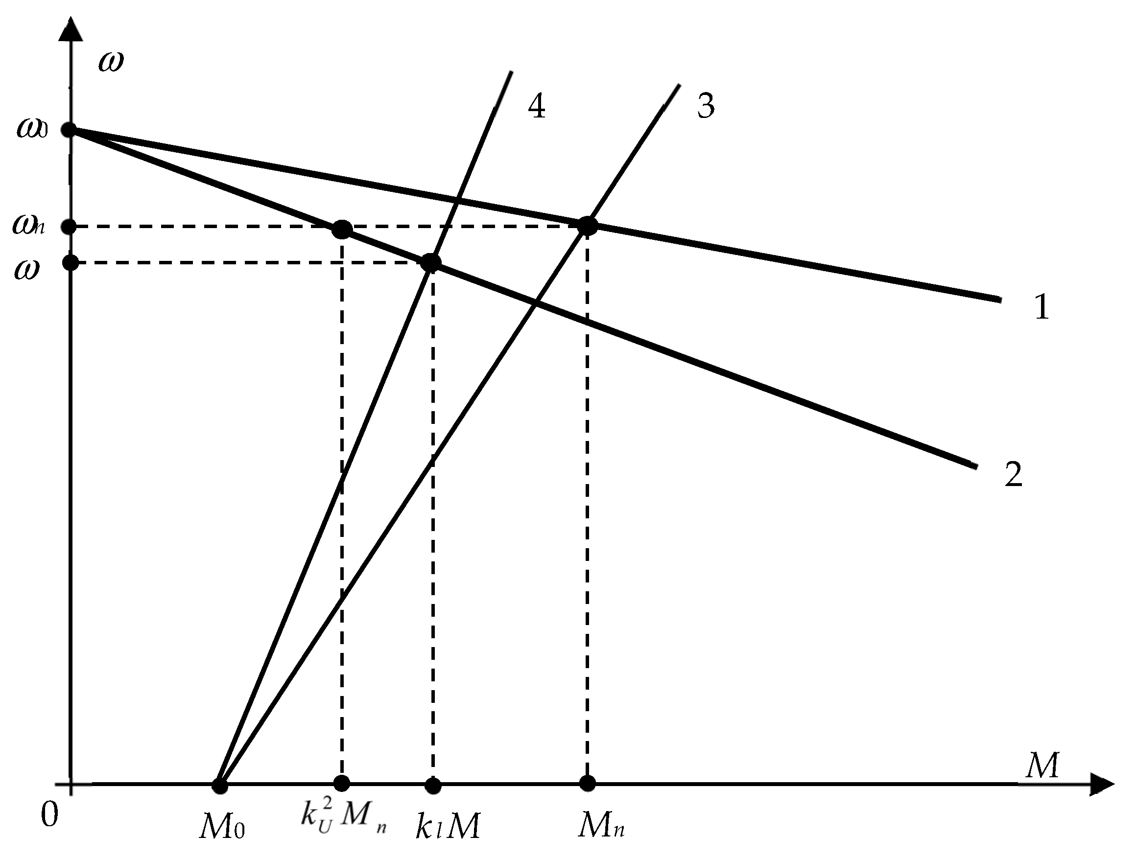
46], but it is not clear how the simultaneous change of voltage and load on the motor shaft affects the slip. Moreover, it is unclear whether it is necessary to take into account the mechanical characteristics of the working machine driven by the electric motor. Therefore, let us analyze the effect of reducing the voltage on the slip of the motor taking into account its load coefficient and the mechanical characteristics of the working machine that it drives. For this purpose, let us use the mechanical characteristics of the three-phase induction motor and the working machine (
Figure 4).
1, 2—linearized working sections of the mechanical characteristics of the induction motor, at nominal and reduced voltage, respectively;
3, 4—mechanical characteristics of the working machine, at nominal and reduced load, respectively;
ω0, ωn, ω—synchronous, nominal and current angular velocity of the induction motor, respectively;
M0—initial resisting torque of the working machine;
Mn, M—nominal and current torques on the motor shaft, respectively;
kl—load coefficient of the motor;
ku—voltage reduction coefficient.
Based on
Figure 4 and the triangle similarity principle,
After transformations of (18), we obtain:
The slip of the motor determines the effective current in the stator and rotor insulations, the square of which determines the amount of heat released during motor operation. Therefore, let us investigate how the motor slip changes depending on the load and voltage reduction coefficients, taking into account the mechanical characteristics of the working machine. To do this, let us use the empirical equation of the mechanical characteristics of the working machine [
32]:
where
Mr,
Mr.n—current and nominal values of the resisting torque of the working machine, respectively,
N⋅m;
x—degree indicator characterizing the change in the static torque of the working machine when its speed changes.
If we apply (19) to (20) under the condition that
M =
Mr, after transformations we obtain:
where
—relative value of the initial resisting torque of the working machine.
Having applied (21), we found the expressions of motor slip depending on the load and voltage reduction factors, taking into account the mechanical characteristics of the working machine (i.e., the value of the degree indicator characterizing the change in the static torque of the working machine when its speed changes).
For a working machine with a mechanical characteristic that does not depend on the speed (
x = 0), this dependence will be as follows:
For a working machine with a ramp mechanical characteristic (
x = 1), this dependence will be as follows:
For a working machine with a parabolic mechanical characteristic (
x = 2), this dependence will be as follows:
For a working machine with a hyperbolic mechanical characteristic (
x = −1), this dependence will be as follows:
Compared to [
45,
46], in Equations (22)–(25), the operating mode of the motor is taken into account more accurately. When controlling the motor, the use of voltage can change the load of the motor, which will require clarification of the voltage value. The mathematical models of the slip given in [
45,
46] do not take this into account and therefore lead to a lower value of optimum voltage. The latter causes the switching of the motor to the overload mode, its overheating, and accelerated thermal wear of its insulation. The mathematical model of the slip proposed in the present work does not have such a drawback because it takes into account simultaneous changes in the voltage and load of the motor. The mains deviation is taken into account through coefficient
ku, and the load of the motor—through coefficient
kl; the mechanical characteristics of the working machine are also taken into account. Thus, the mathematical model of the slip obtained in the work is more universal compared to that in [
45,
46]. The disadvantage of this model is its limited application restricted only by the operating range of the slip; however, it is sufficient for the analysis of the steady-state operating mode of the motor.
3.4. Modelling of the Dependence of the Insulation Thermal Wear Rate of the Induction Motor in the Function of Voltage and Load Taking into Account the Mechanical Characteristics of the Working Machines
Analytical studies allow us to conclude that the rate of thermal wear of insulation is a function of the design and operational performance of the motor and the working machine. The structural parameters of the electric motor are determined by both its general design and its insulation design, and the design parameters of the working machine—by its mechanical characteristics. Performance indicators depend on the mode of operation and take into account the voltage reduction of the motor, its load coefficient, and the temperature of the surroundings. That is, ε = f (εn, B, τ1n, τ1sh, τ1id, ϑsur.n, , , , , P1n, P2n, P3n, sn, M0*, ku, kl, ϑamb). The obtained dependence allows us to calculate the rate of thermal wear of insulation using Equations (1), (7), (17) and (22)–(25). These equations, written in the appropriate sequence, represent an algorithm for calculating ε in relation to the specified design and performance indicators.
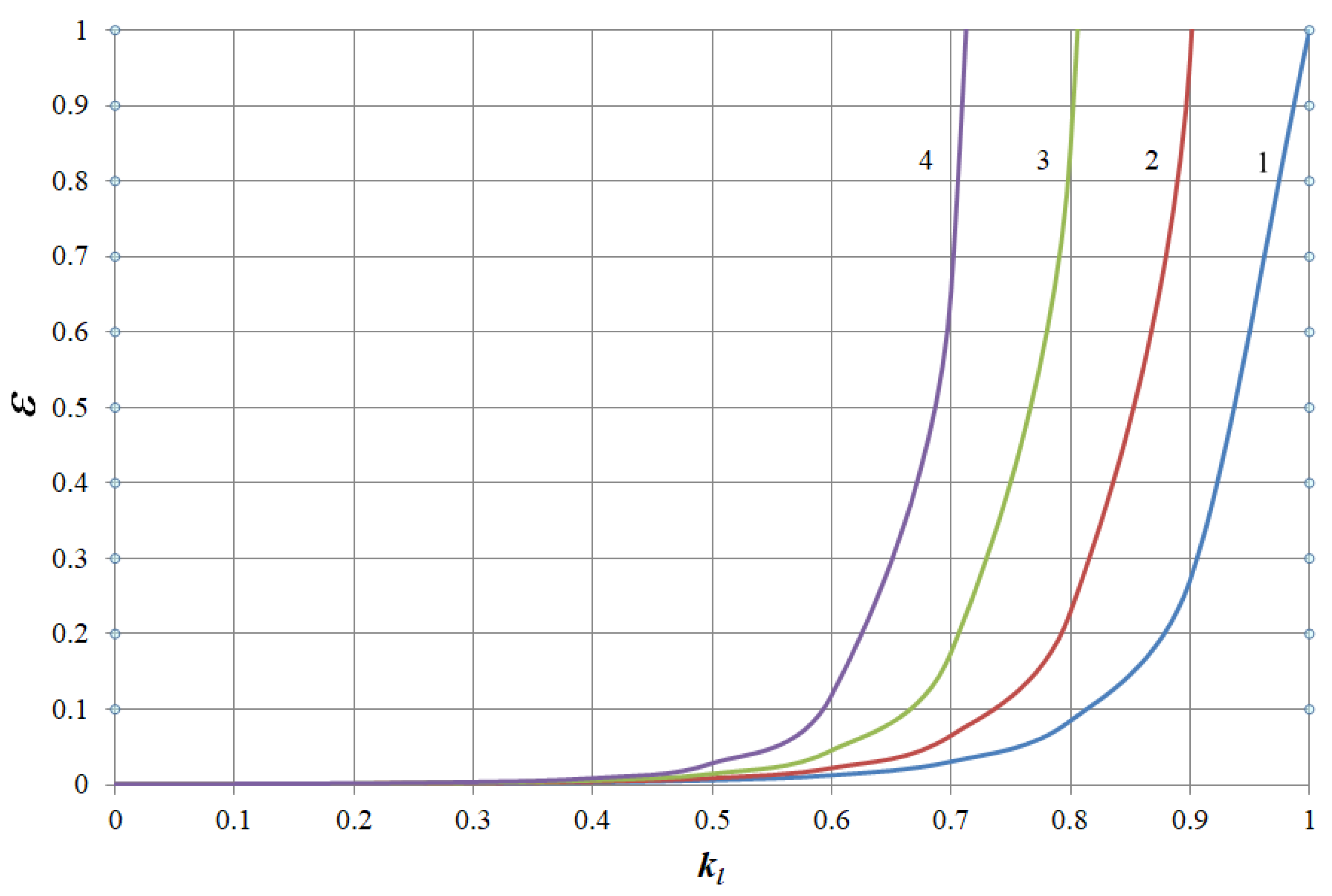
Using the described calculation algorithm, the change in the rate of thermal wear of insulation of the induction motor AIR132S4 (nominal motor power 7.5 kW) was modelled depending on performance indicators: voltage reduction coefficient and load coefficient.
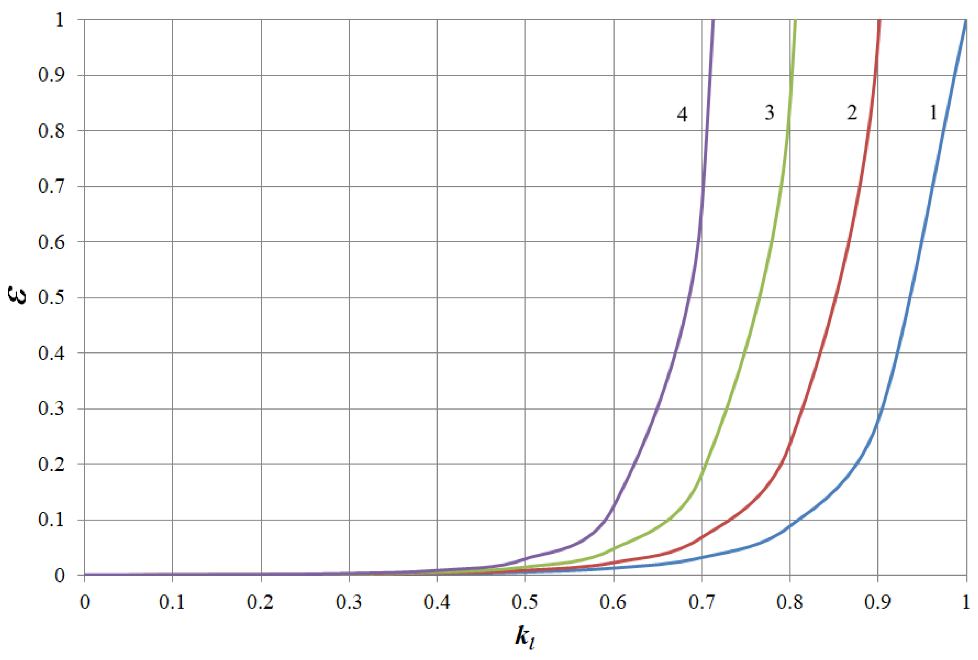
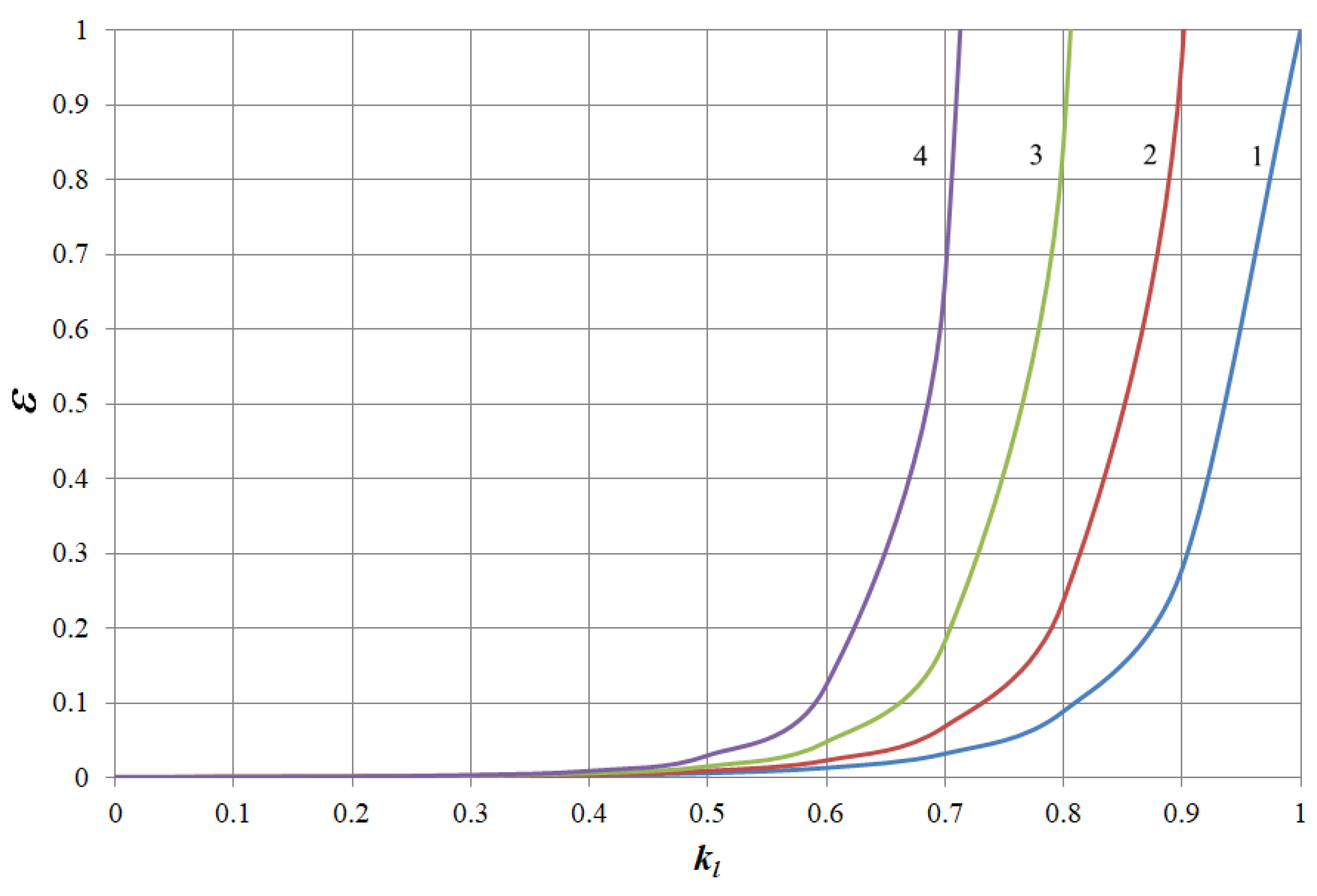
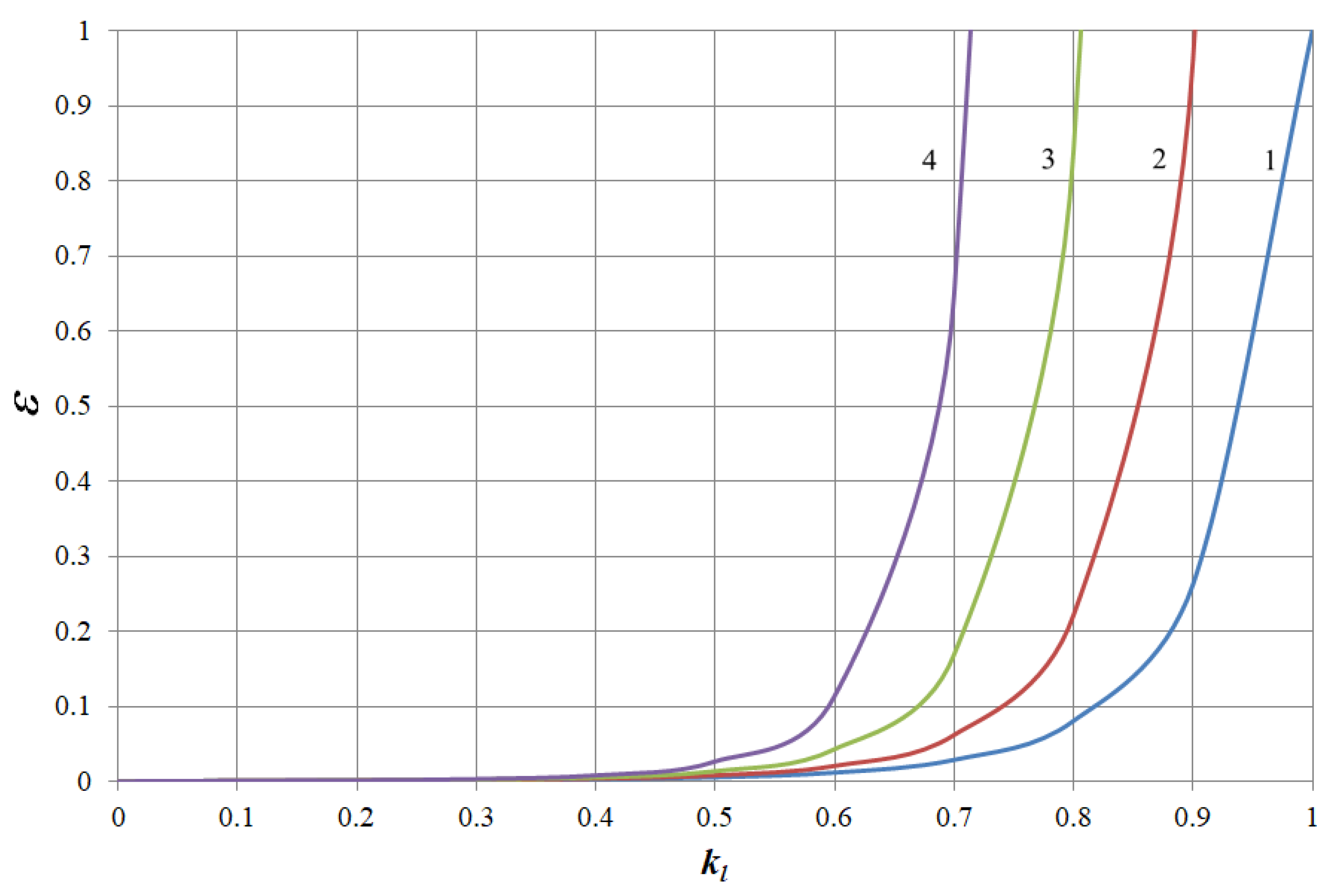
It was assumed that the load coefficient of the motor varies from 0 to 1, the voltage reduction coefficient has the following values: 1.0; 0.95; 0.9; and 0.85, and the temperature of the surroundings is 40 °C.
The results of modelling the dependences
ε =
f (
kl) for electric motors of working machines with different mechanical characteristics are presented in
Figure 5,
Figure 6,
Figure 7 and
Figure 8. The figures show: 1—dependence at
ku = 1; 2—dependence at
ku = 0.95; 3—dependence at
ku = 0.9; 4—dependence at
ku = 0.85.
As can be seen from
Figure 5,
Figure 6,
Figure 7 and
Figure 8, the dependences are of the same type, which is determined by the exponential dependence of the rate of thermal wear of insulation shown in (1). However, the numerical values of the rate of thermal wear of insulation with the same electric motor driving working machines with different mechanical characteristics differ when the voltage is reduced. This can be seen from the results shown in
Table 1,
Table 2,
Table 3 and
Table 4. The tables show examples of the dependence
ε =
f (
kl) at
ku = 0.9 for AIR132S4 induction motor driving working machines with different types of mechanical characteristics.
The above results show that when the motor drives different types of working machines, the rate of thermal wear of its insulation differs at loads close to nominal. This is clearly seen at nominal load, at which it differs by 4 to 10 base hours per hour. In addition, the above results show that when the voltage decreases, the rate of thermal wear of insulation increases sharply. Therefore, for example, at a decrease in voltage of 10% in relation to the nominal voltage and with the electric motor working at nominal load, the rate of thermal wear of insulation depending on the type of the working machine increases by 30–45 times compared to the nominal value. The analysis of the obtained dependencies, shown in
Figure 5,
Figure 6,
Figure 7 and
Figure 8, revealed the following regularities between the voltage reduction coefficient and the load coefficient. Regardless of the type of working machine, the rate of thermal wear of the insulation of the specified motor will be nominal under such conditions:
ku = 1.0 and
kl = 1.0;
ku = 0.95 and
kl = 0.9025;
ku = 0.9 and
kl = 0.81;
ku = 0,85 and
kl = 0.7225. A comparison between these values shows that the load factor equals the square of the voltage deviation coefficient, i.e.,
Similar results were obtained when modelling the rate of thermal wear of insulation of most electric motors in this series.
In order to experimentally test (26) for the AIR132S4 induction motor, a heating test was performed. It was outlined as follows: sinusoidal voltage of a certain value was applied to the motor, and a load of a certain value was applied to the shaft. An adjustable shutter fan was used as the load. The motor was running for 6 h at each voltage value, every 1000 s its insulation temperature was measured using a thermistor, and the temperature of the surroundings was measured with an electronic thermometer. According to the measurement results, the excess of the insulation temperature over the temperature of the surroundings was calculated. The experiments were performed in the following sequence:
Nominal voltage was applied to the motor terminal, and nominal load was applied to the shaft ();
Reduced voltage was applied to the motor terminal (90% of nominal voltage), and nominal load was applied to the shaft;
Reduced voltage was applied to the motor terminal (90% of nominal voltage), and reduced load was applied to the shaft ();
Reduced voltage was applied to the motor terminal (90% of nominal voltage), and reduced load was applied to the shaft ();
Reduced voltage was applied to the motor terminal (90% of nominal voltage), and reduced load was applied to the shaft ().
Cold start of the motor was used, i.e., before each experiment the motor was cooled to the temperature of the surroundings, which remained unchanged during the experimental test. The results of the experimental test are shown in
Figure 9.
Figure 9 shows that the dependences obtained from
and
almost coincide. This indicates the accuracy of the obtained Equation (26).
Let us compare the results with the information given in [
31,
32,
33]. For example, consider the case when the motor drives a working machine with a parabolic mechanical characteristic at the load of 80% of nominal. The results obtained in the work show that according to (26), the rate of thermal wear of insulation will be nominal when the voltage is at least 89.5% of nominal and does not exceed it. Having applied the results of [
31,
32,
33] to the modelling conditions of this work, we will get the following. According to [
31], at the specified motor load, we propose to apply a voltage equal to 86% of nominal. This results in the rate of thermal wear of insulation equal to 3.27 bas.h/h. According to [
32], at the specified motor load, it is proposed to apply voltage equal to 87.2% of nominal. This results in the rate of thermal wear of insulation equal to 2.15 bas.h/h. According to [
33], at the specified motor load, we apply voltage equal to 88.6% of nominal. This results in the rate of thermal wear motor insulation equal to 1.63 bas.h/h.
The comparison shown indicates that all of the control methods presented in works [
31,
32,
33] result in low voltage. This causes the switching of the motor to overload mode and accelerated thermal wear of its insulation. The increased rate of thermal wear of insulation leads to the deterioration of its characteristics and premature failure of the motor. To prevent this from happening, it is necessary to take into account the relationship between the motor load and its voltage by including this relationship into the control algorithm, which is not provided in [
31,
32,
33]. This will ensure the nominal rate of thermal wear of insulation and will prevent the premature failure of the motor. Consideration of the mentioned relationship in the control algorithm is possible if the algorithm includes an additional rule for voltage control. This rule based on (26) has the following form:
The fulfilment of this condition will allow saving the resource of the motor while controlling it by voltage. For example, if the AIR132S4 electric motor drives by a pump unit for 100 h with a load of 80% of nominal, then according to the described voltage control methods, additional wear of its insulation will be observed. According to [
31], it will additionally use (3.27 − 1) × 100 = 227 bas.h/h of the insulation resource. According to [
32], it will additionally use (2.15 − 1) × 100 = 115 bas.h/h of the insulation resource. According to [
33], it will additionally use (1.63 − 1) × 100 = 63 bas.h/h of the insulation resource. By applying the control rule (27), presented in this work, additional wear of insulation is excluded.
4. Conclusions
As a result of the study, by using a three-element thermal equivalent circuit of the induction motor, which is more accurate than that in [
40], the dependence of the steady-state temperature excess of the stator winding on the active power loss in the elements of the circuit under uncertainty of its thermal conductivity has been obtained. This distinguishes the dependence from [
41,
42], which require determining the thermal conductivity. The dependence obtained in the work helps to avoid this by introducing coefficients of power loss impact on the electric motor heating. They have been determined by standard operational tests (idling and short circuit). The power loss coefficient makes it possible to identify the thermal condition of a particular electric motor taking into account the current technical condition of its active parts, which are different in each electric motor. As a result, the obtained dependence is more accurate for a particular electric motor compared to [
40,
41,
42], assuming that all electric motors of a certain size have the same technical condition of active parts.
According to the L-shaped equivalent circuit, the dependence of losses in the three-element thermal equivalent circuit on voltage and load has been obtained. This dependence takes into account the joint effect of voltage deviation and a change in the load of the motor. This approach differs from the existing ones, which take into account either voltage deviation or load change.
The dependence of induction motor slip on voltage and load by imposing the linearized workable range of the mechanical characteristic of the motor and the working machine has been determined for the main types of mechanical characteristics of working machines, which varies for each type of mechanical characteristics of the working machine. This approach, unlike [
45,
46] taking into account only voltage deviations, is more universal. It allows taking into account the main factors of the mode-based nature, which influence the motor slip.
By applying the established dependencies, the modelling of the rate of thermal wear of insulation with various mechanical characteristics at various reduction coefficients of voltage and load (dependence for AIR132S4 electric motor is included in the work) has been performed. The results of modelling have shown that at reduced voltage, the rate of thermal wear of insulation sharply increases. At a decrease in voltage of 10% compared to the nominal value and operation of the motor with nominal load, the rate of thermal wear increases by 30–45 times in relation to the nominal value depending on the type of the working machine.
The dependency of the nominal rate of thermal wear of insulation on voltage has been established. It is as follows: the rate of thermal wear of insulation of the motor is nominal if its load factor equals the square of the voltage reduction coefficient. Verification of this dependency for the temperature of the stator winding showed that the difference between modelling results and the test does not exceed 5%.
By comparing the dependency of the nominal speed of thermal wear of insulation with control methods presented in [
31,
32,
33], the following was obtained. If the electric motor drives a working machine with parabolic mechanical characteristics and is loaded by 80%, according to the obtained dependency, voltage must be no less than 89.5% of nominal and must not exceed it. This results in the nominal rate of thermal wear of insulation, i.e., 1 bas.h/h. Methods described in [
31,
32,
33] not taking into account this regularity lead to undervoltage, which causes an increase in the rate of thermal wear of insulation.
It has been proved that in order to maintain the nominal speed of thermal wear of insulation while controlling it by energy-saving voltage regulation, it is necessary to include an additional rule of voltage regulation in the control algorithm, which states that the coefficient of the voltage reduction of an electric motor must be no less than the square root of its load coefficient and no more than 1. The existing control methods [
31,
32,
33] result in additional wear of insulation. The disadvantage of this rule is the lack of consideration of other influences on the electric motor, except the thermal one.
The obtained rule belongs to the category of algorithmic support of control systems of induction motors and allows extending the service life of electric motors when controlling them by voltage. It is applied in control systems as an additional condition to those involved in them.

 ,
, 


