
Methods for Competitiveness Improvement of High-Temperature Steam Turbine Power Plants


1
Department of Innovative Technologies of High-Tech Industries, National Research University “Moscow Power Engineering Institute”, 111250 Moscow, Russia
2
Department of Thermal Power Plants, National Research University “Moscow Power Engineering Institute”, 111250 Moscow, Russia
*
Author to whom correspondence should be addressed.
Inventions 2022, 7(2), 44; https://doi.org/10.3390/inventions7020044
Submission received: 27 May 2022
/
Revised: 9 June 2022
/
Accepted: 13 June 2022
/
Published: 16 June 2022
(This article belongs to the Special Issue Thermodynamic and Technical Analysis for Sustainability (Volume 2))
Abstract
:The paper is concerned with the problem of the development of high-temperature steam turbine power plants with ultra-supercritical (USC) initial parameters. One of the main disadvantages of the USC power unit’s creation is high price due to the application of expensive heat-resistant materials for boiler, live and reheat steam pipelines in turbines. To solve this problem, the following technical improvements to reduce the application of the heat-resistant materials and equipment metal consumption are proposed: horizontal boiler layout, high temperature steam turbine with a cooling system, oxy-hydrogen combustion chambers, and two-tier low-pressure turbine. The influence of the above-mentioned solutions on the high-temperature steam turbine power plant efficiency was estimated using thermodynamic analysis. The promising equipment design was developed based on the results of numerical and experimental research. The analysis of the proposed solutions’ influence upon the economic parameters of a high-temperature power facility was investigated based on the developed cost analysis model, which included the equipment metal and manufacturing expenses. The introduction of all the mentioned cost reduction methods led to a decrease in the facility’s price by RUB 10.5 billion or 15%. The discounted payback period was reduced from 27.5 to 10 years and the net present value increased by RUB 9.6 billion or 16 times.
1. Introduction
The socioeconomic development of any country is directly associated with an increase in power consumption. The traditional power industry development worldwide and in Russia is based on the use of fossil fuels. Nowadays, the main fuels used are coal, oil, and natural gas. It is worth mentioning that the tendency of hydrocarbon fuel consumption increase is constant (Figure 1a) [1,2], which leads to their exhaustion, environment pollution, and irreversible climate changes. Prospectively, it is a problem that slows down economic growth and threatens mankind’s stable development. Figure 1b shows that more than 40% of electricity production comes from coal fuels and less than 10% is based on nuclear fuels. Steam turbine units are widely used for both nuclear and thermal power plants: they produce about 50% of the world electricity. This emphasizes the high actuality of the problem of increasing the efficiency of steam turbine power plants. Therefore, the problem of increasing the efficiency of coal-fired power plants is a topical one, especially considering the widespread of steam turbine units.
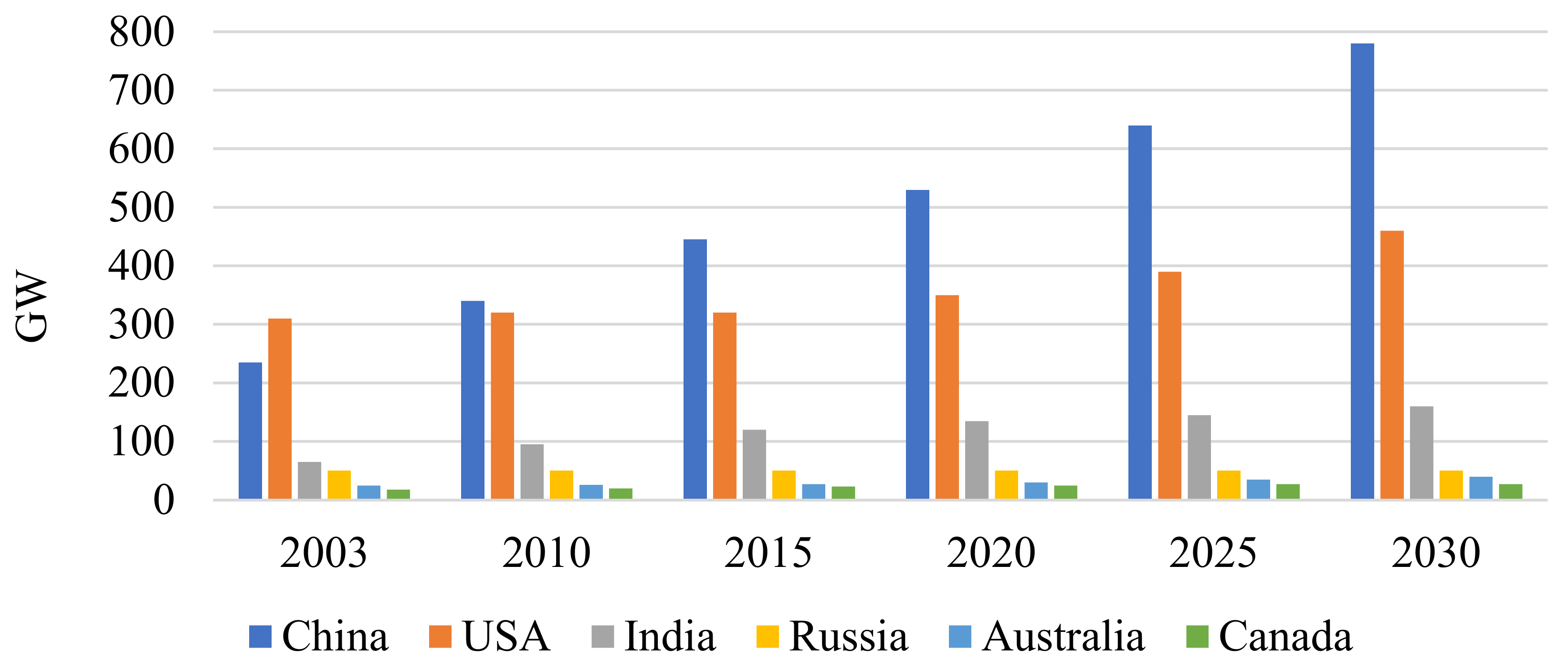
The considered equipment has reached its utmost perfection, so the cycle efficiency may be considerably improved only by an increase in the thermodynamic cycle’s initial parameters. Natural-gas-fired power plants have passed to combined cycles that allow heat supply temperatures of up to 1200–1500 °C and, thus, reach a thermal efficiency of over 60% [3,4,5,6]. Yet, there is no solution for the problem of thermodynamic efficiency enhancement by an increase in initial parameters in coal-fired and nuclear power plants. Nowadays, the most advanced steam turbine coal-fired facilities have reached a thermal efficiency level of 42–43% [7,8]. It is worth mentioning that the total installed power of coal-fired steam turbine facilities every year demonstrates a stable increase (Figure 2) [9,10]. This may be explained by the use of large resources of hard fuels in many countries and the coal price staying constant for many years. Thus, the power industry has a goal to increase the efficiency of coal-fired power plants, which will save fossil fuel resources and reduce the contribution of more expensive fuels, natural gas, and oil products. In addition, it allows environmental harm reduction by the mitigation of toxic NOx and SOx and greenhouse CO2 emissions. Therefore, it is important to find promising ways to improve steam turbine power units.
The next step is the transition from the currently widespread supercritical (SC) initial parameters of 24 MPa and 540 °C to the ultra-supercritical (USC) ones of around 30 MPa and 600 °C. The main drawback of the transition to USC steam parameters is a remarkable increase in the expensive structure materials’ contribution to the total metal expenses. These materials are used for the boiler super-heater, direct and intermediate steam pipelines, and the turbine high-temperature compartments.
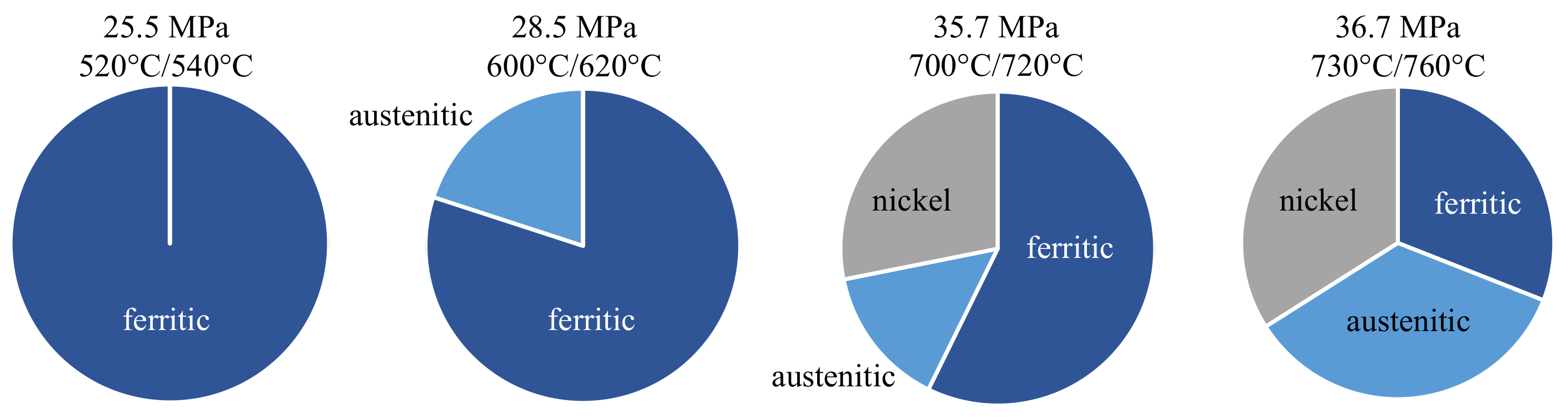
Figure 3 shows the changes in applicable structure materials that follow the transition from SC to USC parameters. Heat-resistant alloys with high nickel contents predominate [11] over the martensite steels that have better thermo-physical performance and are used in SC conditions.
Figure 4 shows the heat-resistant materials’ distribution over the steam turbine facility elements in a USC facility. The main elements that need a transition from the traditional materials to the new heat-resistant and heat-proof ones are the steam superheating surfaces, especially the superheater exit panels, boiler steam collectors, high-temperature live and superheated steam pipelines, check and control valve blocks, turbine internal housings, first stages, and rotors. Therefore, an increase in the initial parameters of steam turbine power units requires a whole range of new alloys and equipment production technologies.
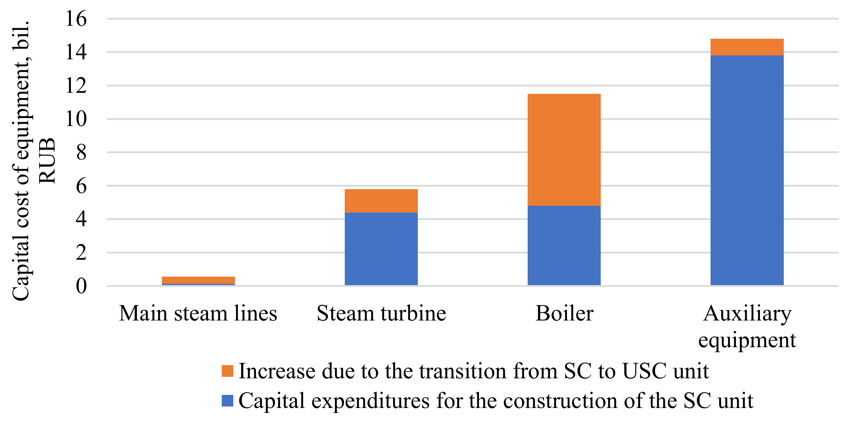
Works on thermal efficiency improvement in the coal-fired power plants are actively being undertaken in many countries [12,13,14,15]. World leaders have already put into operation steam facilities with ultra-supercritical steam parameters of p0 = 32 MPa initial pressure and t0 = 600–620 °C initial temperature [16,17]. These facilities with an efficiency level of 43% are being introduced in large scales in European Union countries, Japan, the USA, and China [18]. The next step in the efficiency improvement needs a transition to a higher level of the initial steam parameters, USC with p0 = 34–36 MPa initial pressure and t0 = 700–760 °C initial temperature. The same leading countries of the EU, Japan, USA, and China actively developed this direction of USC power facilities’ improvement [19,20,21]. The main equipment manufacturers, power production, and research companies have taken part in these programs. The new operation conditions require the development of new materials. In addition to this, the financial factor slows down the introduction of high-temperature power plants, which is due to an increase in the contribution of expensive heat-resistant materials to the metal consumption expenses. The ratio of traditional turbine materials’ cost to that of the heat-resistant steels and alloys cost is 1/5 regarding SC and 1/43 regarding USC. The increase in heat-resistant materials’ contribution is a source of increase in power facilities’ price that results in problems regarding the improvement in financial efficiency despite the remarkable thermal efficiency increase and better environmental performance. The straight steam parameters’ increase from 540 to 720 °C in temperature, together with the pressure rise from 23.5 to 35 MPa, increases the power facility’s price to 20–25% [22]. Figure 5 shows the price increase in the main and auxiliary equipment that follows the SC to USC transition. The main steam pipeline price grows more than three times, the turbine and auxiliary equipment are 30% and 10% more expensive, respectively, and the boiler price is more than two times higher. Therefore, the current methods for increasing the coal-fired power plants’ efficiency require a significant increase in the unit price and may not be economically viable in regions with lower fuel prices.
Thus, one of the key directions of high-temperature power facility improvement and provision of their competitiveness is the reduction in heat-resistant steels’ and materials’ consumption for main equipment manufacturing. Therefore, the main objective of this work is to develop methods to reduce the cost of high-temperature power units and asses their thermodynamic and economic effects.
2. Research Object
2.1. Horizontal Layout of the Energy Boiler for Cost Reduction in Live and Reheat Steam Pipelines
Most of the highly efficient USC steam turbine facilities have between 600 and 1000 MWe power. Available USC facility projects are also designed for high block power. Thus, new solutions concerned with construction cost reduction were applied to the example of a coal-fired 1000 MWe power block with the following parameters: initial steam temperature and pressure 710 °C and 35 MPa, respectively, single intermediate superheating up to 720 °C at 7 MPa pressure, feed water temperature 330 °C, and the condenser pressure 4 kPa. These parameters allow a facility efficiency of 48.5%.
A possible method to achieve a price decrease is the length reduction in primary and superheated steam pipelines. The boiler and turbine layouts have a crucial influence on the pipeline length. The boiler facility parametric study was carried out for a boiler unit firing the Kuznetsk mark D coal and included the thermal, aerodynamic, and design analysis of different boiler layouts. The analysis results are the boiler envelope dimensions and possible design solutions are shown in Table 1.
The design analysis shows that the boiler location concept remarkably influences the length of the main pipelines. The horizontal boiler scheme provides the smallest pipelines’ length and allows for a length reduction of more than three times or 150 m against the most popular in SC and USC towers. The three-time pipeline length reduction provides a corresponding price decrease.
2.2. Cooling as a Method for Reduction in Heat-Resistant Materials’ Consumption for High-Temperature Steam Turbine
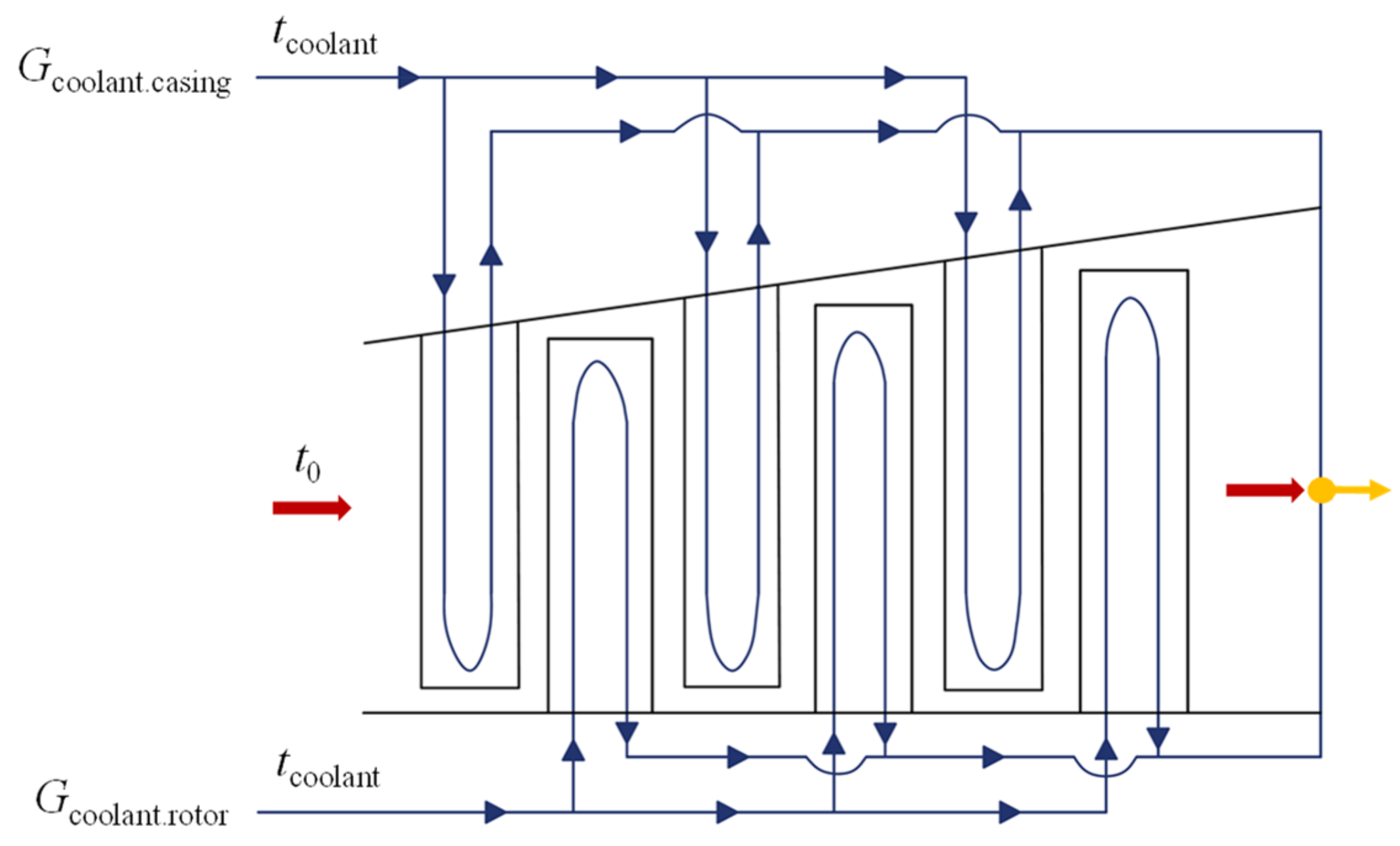
The application of high-temperature turbine elements’ cooling is another way to reduce the consumption of heat-resistant materials. It is worth mentioning that this method inevitably reduces the power facility efficiency that is caused by the working fluid bleeding and the resulting turbine power drop. Another disadvantage is the increase in the complexity of the turbine manufacturing technology. Figure 6 presents a flow chart of the cooled turbine compartment with the blades and vanes convective cooling. The high temperature flow enters the compartment with the initial temperature. The blades are cooled with the coolant that is distributed between the turbine stages from a collector. The cooling agent flow cools the blades and enters the flow path immediately downstream of the cooled compartment. The result is the mixing of the cooling agent with the working fluid at the cooled compartment exit and downstream mixture expansion in the non-cooled turbine compartment.
The energy effects of the applied cooling were evaluated by a specially developed model of the cooled turbine compartment. Equations (1) and (2) determine the cooling steam flow and the cooled compartment power, respectively, for different temperature levels of the initial steam, cooling agent, and operating metal.
Equation (1) allows the calculation of the specific compartment cooling flow.
where
- Gcoolant—cooling agent mass flow to a grid, kg/s;
- G0—working fluid mass flow at the grid inlet, kg/s;
- tcoolant.in—cooling agent temperature at the blades cooling channels inlet, °C;
- tmet—metal operating temperature, °C.
Equation (2) determines the cooled compartment power Ncooled.comp.
These equations were used for the computer simulation of the thermal flow charts of high-temperature power facilities with cooled turbines. The cooling of the high-temperature turbine parts and the initial steam temperature t0 = 700–800 °C do not remarkably reduce the facility efficiency because of the rather small cooling agent mass flow. At the initial temperature of 700–720 °C, the efficiency reduction is about 0.5% and the metal temperature may be reduced to 600 °C, which corresponds to the USC power facilities. This level of the metal temperature allows the application of cheaper mass production structure materials. Thus, the equipment development cost may be reduced and the problems of the equipment reliability and endurance may be solved.
2.3. Oxy-Hydrogen Combustion Chamber Reduces Heat-Resistant Materials’ Consumption for Energy Boiler
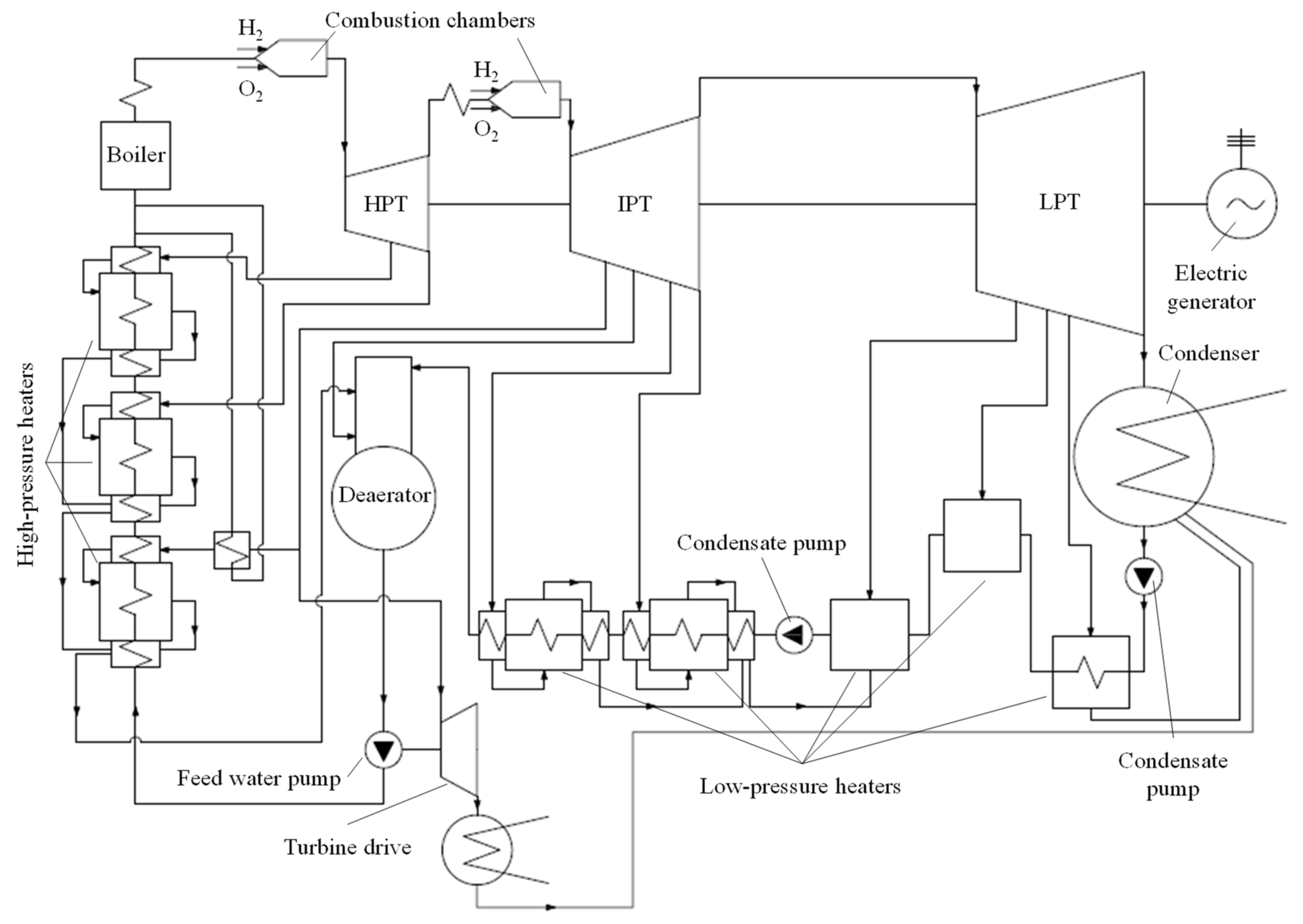
Figure 5 shows that the main contribution to the increase in power facility cost is the boiler price. This increase is caused by the remarkable increase in heat-resistant materials’ consumption in high-temperature superheater manufacturing. A possible method to reduce heat-resistant materials’ consumption is the steam superheating in hydrogen–oxygen combustors, where the heat is transferred not through the heat transfer surface, but by mixing the boiler bleeding steam flow with the high-temperature combustion products. This type of heat transfer allows a much higher temperature that is limited in traditional facilities by the limited performance of the superheater surface’s structure materials. Figure 7 presents a heat flow chart for this type of facility with a high-temperature steam superheater.
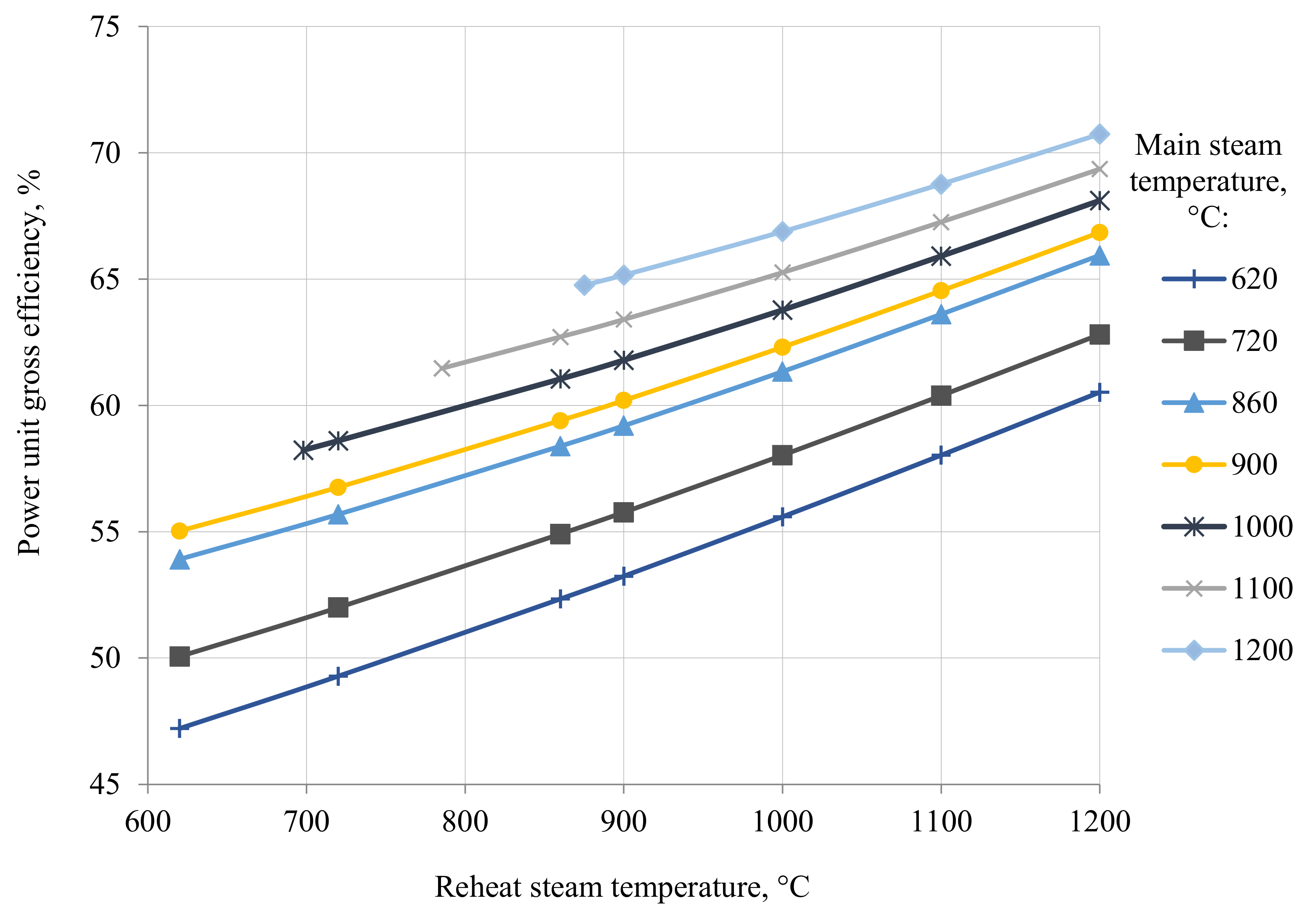
Figure 8 shows the influence of the reheater on the power facility’s gross efficiency at different main steam temperatures. The range of the straight flow and the intermediate superheated steam is verified from the boiler exit to 1200 °C. The dependencies show that the steam superheating up to the USC level provides a facility gross efficiency of 51–53%, which corresponds to a net efficiency of 48–49%.
We propose to burn hydrogen in the oxygen–steam environment where the oxidizing agent is the mixture of oxygen and the water steam produced in the boiler. This solution corresponds to a flame temperature reduction of 2000–2200 °C, which ensures the reliable operation of the combustor metal and is typical for gas turbine combustor flames. The combustion temperature drop caused by the oxidizer ballasting with the water steam inevitably causes the mixture reaction capability. This requires a combustor design with reliable flame stabilization. An approved technical solution is the combustor with an airfoil swirler.
2.4. Two-Tier Low-Pressure Turbine
The reduction in metal consumption and improvement in the facility efficiency may be reached not only in the turbine high-temperature compartment. The low-temperature compartment of powerful turbines also has large reserves that are helpful in the reduction in metal consumption and improvement in the low-pressure turbine’s (LPT) aerodynamic performance. The most prospective method for metal consumption reduction is the increase in the total LPT exhaust area, which may be reached by an increase in their flow capacity.
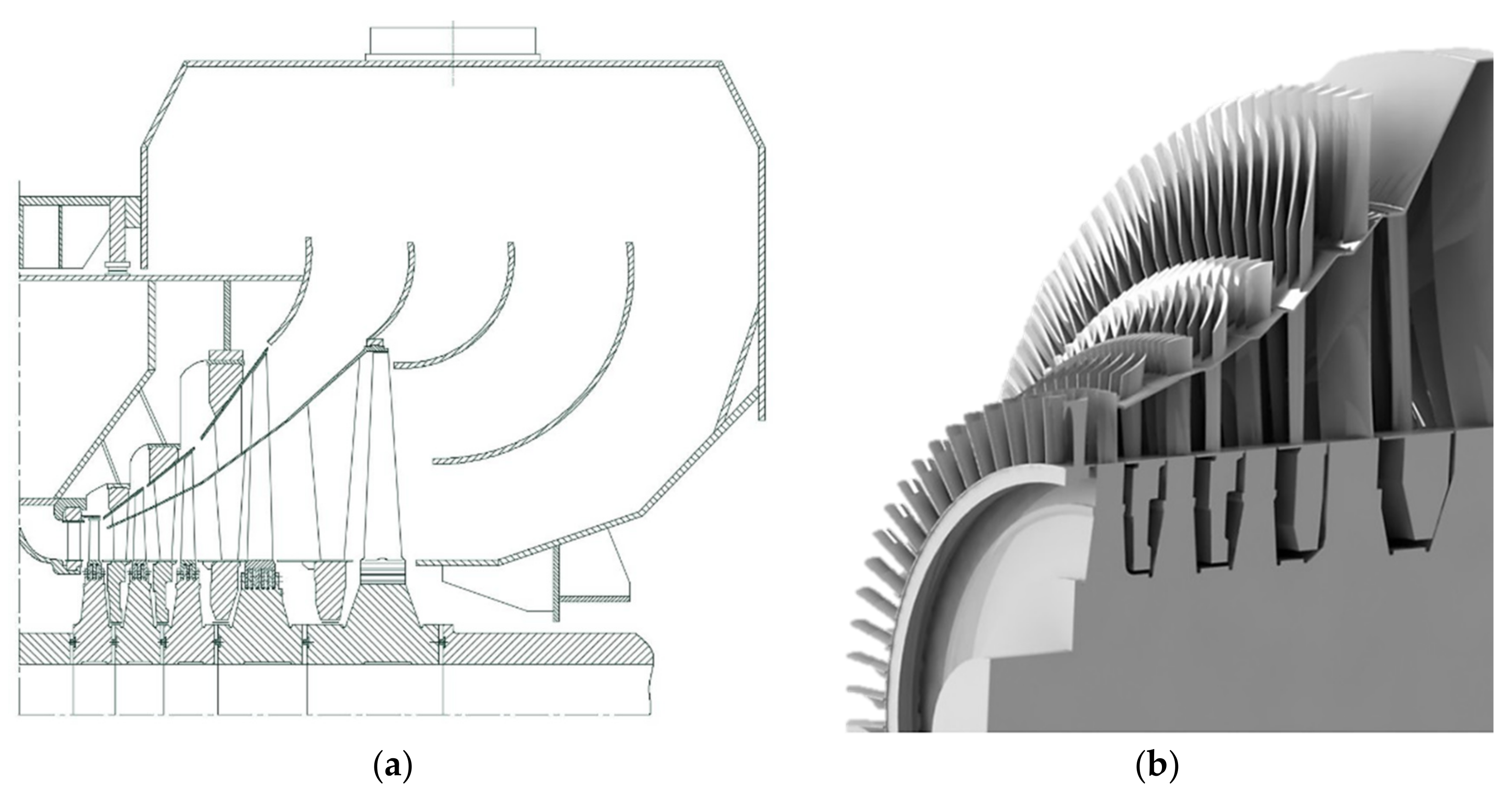
A possible way to achieve a LPT flow capacity increase is to transition to a two-tier flow path. The top tier is an airfoil grid independent from the root tier with its optimal pitches, airfoils, and reaction degrees. Figure 9 presents the design and 3D model of a two-tier flow path with increased flow capacity.
In the proposed flow path design, the flow passes the first LPT stage and splits. The main part of the flow continues its expansion in the four stages of the lower tier and the other part expands down to the condenser pressure in the three stages of the top tier. There is a reduced number of top tier stages because the stage diameters are larger than those of the lower tier. Therefore, the heat drops in the second-tier stages are larger than those in the lower tier ones.
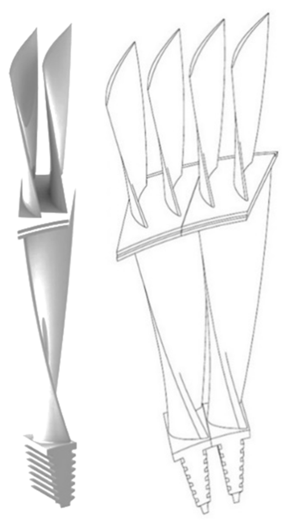
The two-tier blades are at the base of the two-tier flow path. It is reasonable to design the first two blades with equal blade numbers in the top and lower tiers. The last two-tier stage has different numbers of blades in the tiers. This design has a higher aerodynamic efficiency caused by lower fan factor losses. This technical solution corresponds with the “fork” blade shown in Figure 10.
The two-tier blades are loaded with higher tension stresses than the traditional ones. This is concerned with the inter-tier shroud that is one of the most loaded zones of the structure. The 3D stress analysis shows that the needed stress safety factor above 2.8 may be provided by the titanium blade material and an inter-tier shroud thickness of at least 20 mm.
The developed LPT design allows an increase in the condenser steam flow up to 40%. Therefore, the number of exhaust ducts may be reduced, which reduces the turbine metal consumption and price. The two-tier LPT flow path is surely a more complicated technical solution than the traditional ones, but the proposed fork-shape blade with the top tier larger number of airfoils eliminates the fan factor losses. The “one-and-a-half” exhaust from the two-tier stage is free from the Bauman stage shortages. In addition, it is a solution for the >1200 mm span blades that experience strength and aerodynamic problems concerned with the fan factor and the large flow path expansion angle. The developed solutions provide the LPT internal relative efficiency of 87.1% that is equal or in some cases higher than the traditional LPT level.
3. Methods
The key cost item for the manufacture of the main power equipment is metal costs—the sum of the costs associated with the purchase of blanks for the manufacture of steam turbine parts and boiler plant structures. The increase in the cost of creating power equipment with an increase in the initial steam parameters is explained not only by the rise in the cost of the steel grades used and the increase in their share in the structure of metal costs, but also by the change in the weight and size characteristics of components and parts of steam turbines and boiler units [23]. The need to consider metal costs in the first place is also due to the presence of a direct relationship between the labor intensity of manufacturing parts of equipment and the dimensions of products, their number, and materials used for manufacturing. In fact, metal costs determine, to a large extent, the costs associated with the manufacture of equipment. Other costs, in particular, the costs incurred in the performance of research and development, design costs, as well as fixed costs associated with the remuneration of administrative and management personnel and the maintenance of production and technological equipment, do not depend on the parameters under consideration and may act as a constant.
In turn, an increase in steam temperature leads to a decrease in the ultimate strength, which necessitates the thickening of parts of the power equipment operating under pressure. The austenitic steels used in high-temperature zones of power units usually have a higher specific gravity (8600 kg/m3) than the steels of pearlite grades (7800–7900 kg/m3) widely used in power unit equipment for steam parameters of 23.5 MPa/540 °C. An increase in steam temperature increases the available heat drop in turbine plants, which leads to an increase in the length of the rotor and housing, as well as an increase in the mass of the blade apparatus due to an increase in the number of stages. Additionally, an increase in steam temperature increases the specific volume of steam, which requires an increase in the area of the flow section of the flow path of the steam turbine, and, accordingly, there is an increase in the height of the blades, diaphragms, and the thickness of the casing wall, due to an increase in the inner diameter. In boiler plants, an increase in steam temperature leads to the need to increase the heat exchange area, which also contributes to an increase in the mass of heating surfaces. An increase in pressure leads to an obvious need to increase the wall thickness of the pipes of heating surfaces, collectors, steam turbine casings, and the thickness of the walls of steam pipelines.
The cost estimation models that take into account all these technical features are possible only on the basis of a cost approach, within which it is necessary to develop functional dependences of the masses of parts and assemblies of power equipment on the initial steam parameters. To solve this problem, it is necessary to identify factors that affect the metal consumption of power equipment and establish their relationships.
The first step in building a cost estimation model is to decompose the equipment into its component parts and, further, perform a breakdown to the level of parts and assemblies. The reason for using this method is the fact that the change in the costs associated with the manufacture of a power unit equipment as a whole consists of individual increases in the costs of manufacturing composite parts and structural elements.
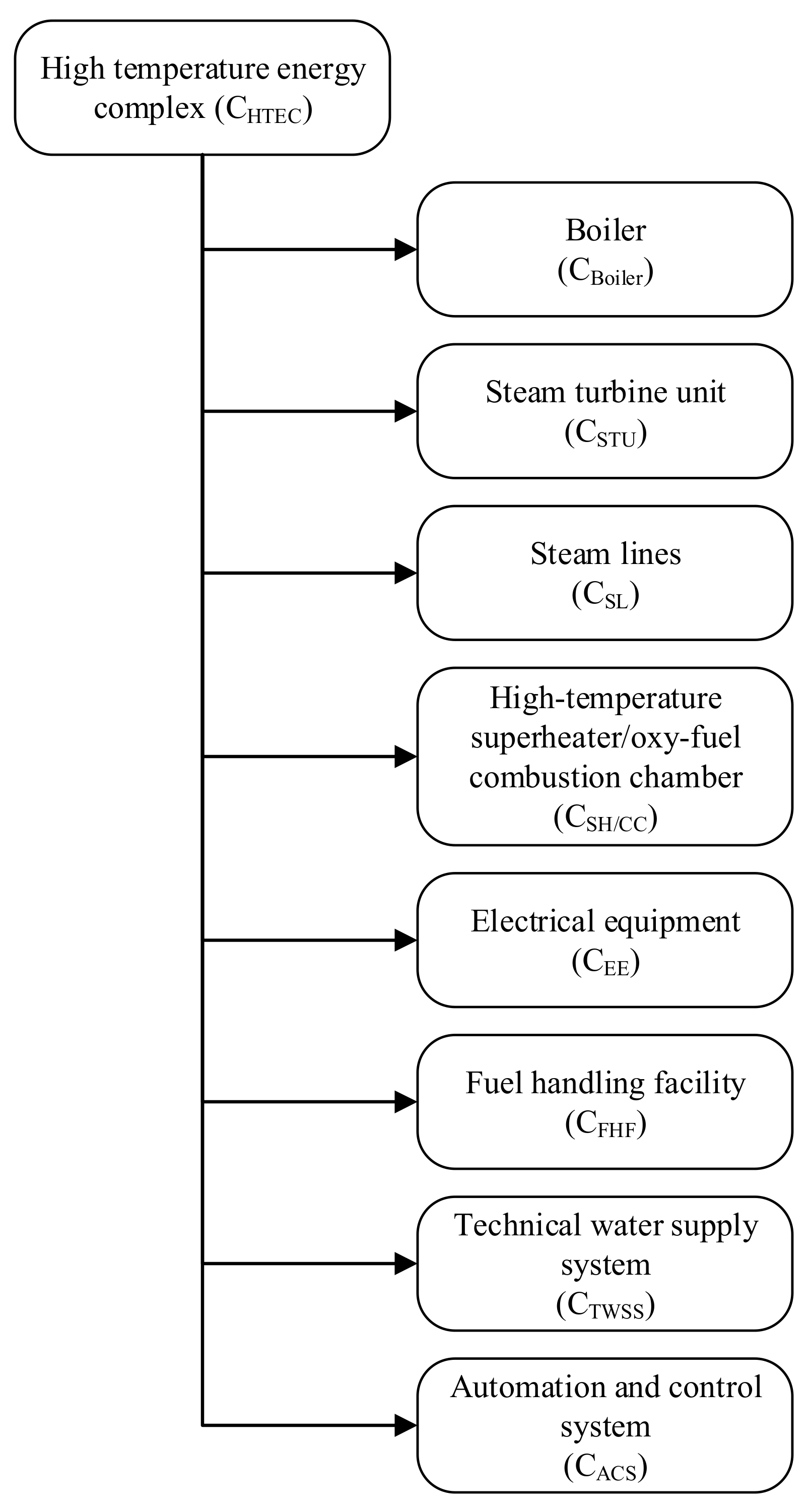
An enlarged analysis of the systems and units and their functions that are part of the high-temperature energy complex is shown in Figure 11. Therefore, one can say that special attention should be paid to the cost of systems that provide the generation and superheating of steam (CBoiler and CSH/CC), the conversion of the thermal energy of the working fluid into electrical energy (CSTU), as well as systems that ensure the transportation of high-temperature coolant (CSL). Such systems include a steam generator (steam boiler), a steam turbine unit, steam pipelines, and a hydrogen–oxygen combustion chamber. Other systems that provide the functions of fuel preparation and supply (CFHF), transmission and conversion of electrical energy (CEE), turbine condenser cooling (CTWSS), and power complex control (CACS) do not undergo significant qualitative changes with an increase in initial parameters. In this connection, it is advisable to predict their cost, focusing on analogues used in the construction of energy facilities with an already mastered level of initial steam parameters, taking into account their capacity.
The determination of metal costs is based on finding the volume of the part according to the geometric characteristics, which depend on the initial parameters of the steam and its consumption. Based on the obtained data on the volume of the part, taking into account the selected brand, the structural material was calculated. The mass of blanks used for the manufacture of parts was determined by dividing the net mass of the part by the material efficiency factor.
Another major cost item directly related to the production of power equipment is manufacturing costs that are heterogeneous in nature, including labor costs for production personnel, costs for equipment and tools, deductions for depreciation, and repair of machine tools. Structurally, manufacturing costs include both fixed (machine repair, depreciation, and tooling manufacturing) and variable costs (labor costs for production personnel and tools). An accurate assessment of this type of cost is impossible without the parameters of the organization of a specific production process at a single plant. However, when estimating the cost of production orders, factories often use the term “machine-hour”, which is the amount of unit costs per unit of time (hour) directly related to ensuring the operation of production equipment. With a fixed value of the cost of a machine-hour, the total cost of manufacturing final products is directly proportional to the labor intensity of a single part.
At the final stage of estimating the costs of manufacturing parts of power equipment, all the functions obtained are synthesized and integrated into a general model for estimating the cost of equipment. A transition is being made from natural units of measurement of time and materials to cost ones by multiplying them for each item of equipment by the cost of a machine-hour and the price of steels and alloys, respectively. After that, the costs are aggregated by parts of power equipment, on the basis of which the production cost of the units is determined. The cost of the power units being researched was, therefore, calculated following the equation:
On the basis of the power units cost, the traditional economic parameters of high-temperature energy complexes were calculated (such as the net present value and discounted payback period) using algorithms written in Python.
4. Results and Discussion
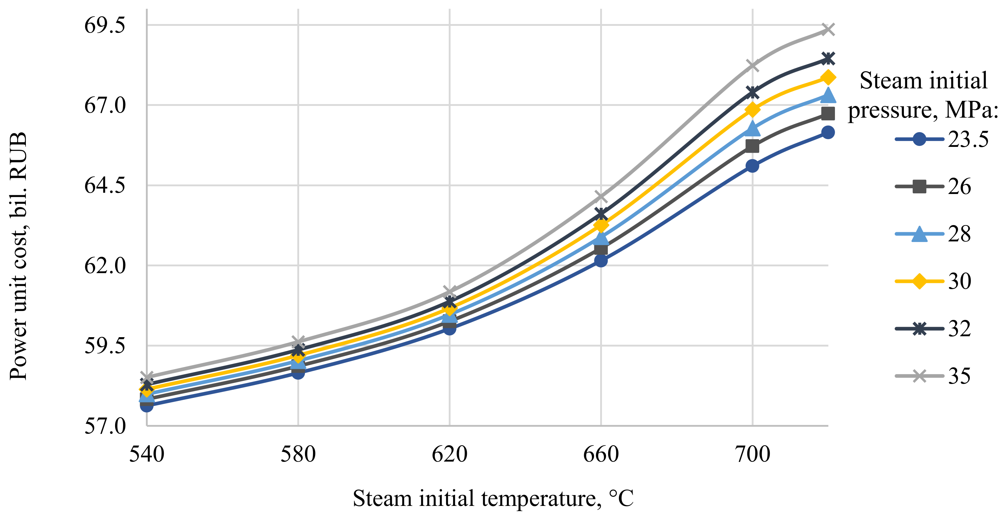
Figure 12 shows changes in the facility construction cost concerned with the initial steam parameters changes. The steam temperature increase at a constant pressure remarkably influences the power facility cost. The increase in steam temperature from 540 to 720 °C and pressure from 23.5 to 35 MPa increases the power facility construction cost from RUB 57.6 to 69.4 billion. Therefore, the transition from SC to USC increases the facility cost by 20.4%.
Financial assessments (Table 2) show that the new technical solutions devoted to the cost reduction in high-temperature power facilities allow a block cost reduction of RUB 10.5 billion. Therefore, the USC power plant price becomes similar to that of the traditional SC power plant.
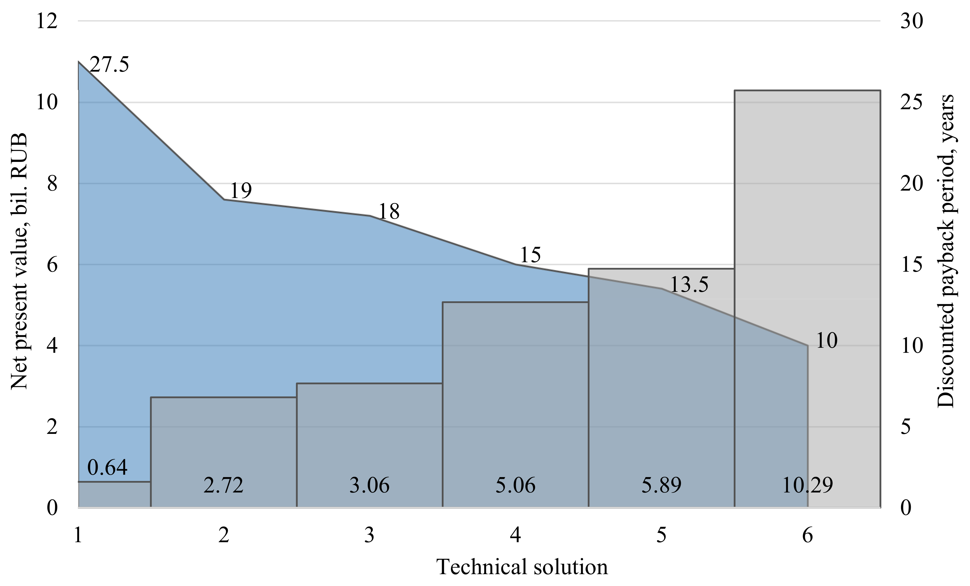
The new technical solutions influence the financial performance of the high-temperature power facilities’ construction. Figure 13 shows discounted payback periods (blue color) and discounted payment flow (gray color) values according to different contents of the applied technical solutions.
The transition to higher steam parameters improves power production efficiency and reduces fuel expenses. On the other hand, it requires larger capital investments, amounts of depreciation, and maintenance expenses. The proposed solutions reduce the capital investments but do not hurt the power production efficiency, so Figure 13 demonstrates the discounted payback period shortened from 27.5 to 10 years and an increase in the discounted payment flow from RUB 0.64 to 10.29 billion.
5. Conclusions
The significant cost of high-temperature steam turbine power facilities is caused by the large consumption of expensive heat-resistant materials and is one of the key problems of these power plants’ introduction. A prospective way to overcome the problem is the development of solutions ensuring technology availability and financial feasibility. In this study, the following solutions for high-temperature steam turbine power facilities were developed and assessed:
- -
- Horizontal boiler design that reduces the high-temperature pipelines’ length by three times or 150 m for the most widespread designs, which leads to a corresponding decrease in steam lines’ cost;
- -
- Application of a cooled steam turbine that reduces heat-resistant materials’ consumption by allowing the operation of metal at 600 °C and allows the maintenance of the high thermal efficiency level of the power cycle;
- -
- Smaller consumption of heat-resistant materials achieved by the transition of steam superheating from boiler surfaces to the external hydrogen–oxygen combustion chamber;
- -
- Smaller material consumption in high velocity powerful steam turbines by the application of two-tier last LPT stages with an up to 40% higher flow capacity at 87.1% efficiency.
To assess the economic potential of the proposed methods, a cost analysis model was developed on the basis of power equipment costs of metal and manufacturing. According to the results of the calculations, an application of all of the proposed methods allows for a reduction in the high-temperature power facility cost by RUB 10.5 billion or 15%. The discounted payback period is reduced from 27.5 to 10 years and the net present value increases by RUB 9.6 billion or 16 times.
In further research, the experimental study of physical processes occurring in the flow path of full-scale equipment should be considered. Oxy-hydrogen combustion with a water steam diluent in high-pressure combustors is of special scientific interest. Moreover, gas dynamic and strength tests of two-tier flow paths are actual tasks that should be performed.
Author Contributions
Conceptualization, N.R. and A.R.; methodology, I.K.; software, V.K.; validation, I.K. and S.O.; formal analysis, S.O.; investigation, V.K.; resources, I.K.; data curation, S.O.; writing—original draft preparation, V.K.; writing—review and editing, N.R.; visualization, S.O.; supervision, N.R.; project administration, A.R.; funding acquisition, A.R. All authors have read and agreed to the published version of the manuscript.
Funding
This study was conducted by the Moscow Power Engineering Institute and was financially supported by the Ministry of Science and Higher Education of the Russian Federation (project no. FSWF-2020-0020).
Institutional Review Board Statement
Not applicable.
Informed Consent Statement
Not applicable.
Data Availability Statement
Not applicable.
Conflicts of Interest
The authors declare no conflict of interest. The funders had no role in the design of the study; in the collection, analyses, or interpretation of data; in the writing of the manuscript, or in the decision to publish the results.
References
- IEA. Electricity Information 2017; OECD Publishing: Paris, France, 2017. [Google Scholar] [CrossRef]
- Lisin, E.; Rogalev, A.; Strielkowski, W.; Komarov, I. Sustainable Modernization of the Russian Power Utilities Industry. Sustainability 2015, 7, 11378–11400. [Google Scholar] [CrossRef] [Green Version]
- Vandervort, C. Advancements in H Class Gas Turbines and Combined Cycle Power Plants. In Proceedings of the Volume 3: Coal, Biomass, and Alternative Fuels; Cycle Innovations; Electric Power; Industrial and Cogeneration; Organic Rankine Cycle Power Systems; American Society of Mechanical Engineers: Oslo, Norway, 2018; p. V003T08A007. [Google Scholar]
- Paudel, A.; Bandhauer, T. Techno-Economic Analysis of Waste Heat Recovery Systems for Wet-Cooled Combined Cycle Power Plants. Appl. Therm. Eng. 2018, 143, 746–758. [Google Scholar] [CrossRef]
- Alqahtani, B.J.; Patiño-Echeverri, D. Integrated Solar Combined Cycle Power Plants: Paving the Way for Thermal Solar. Appl. Energy 2016, 169, 927–936. [Google Scholar] [CrossRef] [Green Version]
- Edris, M. Comparison between Single-Shaft and Mutli-Shaft Gas Fired 800 MWel Combined Cycle Power Plant. Appl. Therm. Eng. 2010, 30, 2339–2346. [Google Scholar] [CrossRef]
- Geete, A. Application of Exergy and Entransy Concepts to Analyses Performance of Coal Fired Thermal Power Plant: A Case Study. Int. J. Ambient. Energy 2021, 42, 1032–1043. [Google Scholar] [CrossRef]
- Rogalev, A.; Komarov, I.; Kindra, V.; Zlyvko, O. Entrepreneurial Assessment of Sustainable Development Technologies for Power Energy Sector. JESI 2018, 6, 429–445. [Google Scholar] [CrossRef] [Green Version]
- Yeh, S.; Rubin, E.S. A Centurial History of Technological Change and Learning Curves for Pulverized Coal-Fired Utility Boilers. Energy 2007, 32, 1996–2005. [Google Scholar] [CrossRef]
- Levina, E. The Coal Market and Coal-Based Electricity Generation: Global Perspectives; JSC “VTI”: Moscow, Russia, 2014; pp. 17–30. [Google Scholar]
- Marion, J.; Drenik, O.; Frappart, C.; Kluger, F.; Sell, M.; Skea, A.; Vanstonee, R.; Walker, P. Advanced Ultra-Supercritical Steam Power Plants. In Proceedings of the Workshop on Advanced Ultra-Supercritical Coal-Fired Power Plants, Vienna, Austria, 19–20 September 2012. [Google Scholar]
- Xu, C.; Li, X.; Liu, X.; Li, J. An Integrated De-Carbonization Supercritical Coal-Fired Power Plant Incorporating a Supplementary Steam Turbine, Process Heat Recovery and a Modified Boiler Structure. Appl. Therm. Eng. 2020, 178, 115532. [Google Scholar] [CrossRef]
- Mathews, I.; Mathews, E.H.; van Laar, J.H.; Hamer, W.; Kleingeld, M. A Simulation-Based Prediction Model for Coal-Fired Power Plant Condenser Maintenance. Appl. Therm. Eng. 2020, 174, 115294. [Google Scholar] [CrossRef]
- Desideri, U.; Antonelli, M. A Simplified Method for the Evaluation of the Performance of Coal Fired Power Plant with Carbon Capture. Appl. Therm. Eng. 2014, 64, 263–272. [Google Scholar] [CrossRef]
- Rogalev, A.; Kindra, V.; Komarov, I.; Osipov, S.; Zlyvko, O. Structural and Parametric Optimization of S-CO2 Thermal Power Plants with a Pulverized Coal-Fired Boiler Operating in Russia. Energies 2021, 14, 7136. [Google Scholar] [CrossRef]
- Lisyanskii, A.S.; Gribin, V.G.; Sakhnin, Y.A.; Fat’kov, O.V.; Gorlitsyn, K.V.; Ushinin, S.V. Practical Experience with the Introduction of Honeycomb Shroud Seals on 250–800 MW Supercritical Pressure Units. Power Technol. Eng. 2014, 47, 440–445. [Google Scholar] [CrossRef]
- Hald, J. Prospects for Martensitic 12% Cr Steels for Advanced Steam Power Plants. Trans. Indian. Inst. Met. 2016, 69, 183–188. [Google Scholar] [CrossRef]
- Xu, G.; Xu, C.; Yang, Y.; Fang, Y.; Zhou, L.; Yang, Z. Thermodynamic and Economic Analysis of a Partially-Underground Tower-Type Boiler Design for Advanced Double Reheat Power Plants. Appl. Therm. Eng. 2015, 78, 565–575. [Google Scholar] [CrossRef]
- Xu, G.; Xu, C.; Yang, Y.; Fang, Y.; Li, Y.; Song, X. A Novel Flue Gas Waste Heat Recovery System for Coal-Fired Ultra-Supercritical Power Plants. Appl. Therm. Eng. 2014, 67, 240–249. [Google Scholar] [CrossRef]
- Vu, T.T.; Lim, Y.-I.; Song, D.; Mun, T.-Y.; Moon, J.-H.; Sun, D.; Hwang, Y.-T.; Lee, J.-G.; Park, Y.C. Techno-Economic Analysis of Ultra-Supercritical Power Plants Using Air-and Oxy-Combustion Circulating Fluidized Bed with and without CO2 Capture. Energy 2020, 194, 116855. [Google Scholar] [CrossRef]
- Braimakis, K.; Magiri-Skouloudi, D.; Grimekis, D.; Karellas, S. Εnergy-Exergy Analysis of Ultra-Supercritical Biomass-Fuelled Steam Power Plants for Industrial CHP, District Heating and Cooling. Renew. Energy 2020, 154, 252–269. [Google Scholar] [CrossRef]
- Komarov, I.I.; Rogalev, N.D.; Rogalev, A.N.; Zlyvko, O.V.; Lvov, I.V. Influence of Initial Steam Parameters on Financial and Economic Indicators of High-Temperature Steam Turbine Power Units. New Russ. Power Ind. 2016, 9, 23–40. [Google Scholar]
- Kindra, V.; Rogalev, A.; Lisin, E.; Osipov, S.; Zlyvko, O. Techno-Economic Analysis of the Oxy-Fuel Combustion Power Cycles with Near-Zero Emissions. Energies 2021, 14, 5358. [Google Scholar] [CrossRef]
Figure 1.
A split of world power production between primary energy sources: (a) Changes from 1974 to 2014; (b) Power source structure for the 2014 year.
Figure 1.
A split of world power production between primary energy sources: (a) Changes from 1974 to 2014; (b) Power source structure for the 2014 year.

Figure 2.
Growth of coal-fired power plants’ installed power.

Figure 3.
Changes in the streel assortment for power facilities at different steam parameters.

Figure 4.
Heat-resistant materials in the USC power facility equipment.

Figure 5.
Increase in power facility equipment price caused by the transition to USC.

Figure 6.
Analysis chart of a steam turbine cooled compartment.

Figure 7.
Thermal flow chart of the power facility with doubled hydrogen superheating.

Figure 8.
Efficiency of a hybrid power facility with two hydrogen superheaters.

Figure 9.
The two-tier LPT: (a) Axial cross-section; (b) 3D model.

Figure 10.
“Fork”-shape two-tier blade.

Figure 11.
High-temperature energy complex cost decomposition.

Figure 12.
Influence of the initial steam parameters on the cost of a coal-fired power plant.

Figure 13.
Financial performance of projects for high-temperature facilities construction.


Table 1.
Versions of the USC power facility layout.
| Conventional Arch Boiler, Horizontal Arrangement | T-Shaped Boiler, Horizontal Arrangement |
 |  |
| Live steam piping length: 53.8 m; Reheat steam piping length: 51.9 m; Total length: 105.7 m. | Live steam piping length: 68.8 m; Reheat steam piping length: 82.2 m; Total length: 150 m. |
| Conventional arch boiler, standard arrangement | T-shaped boiler, standard arrangement |
 |  |
| Live steam piping length: 96.2 m; Reheat steam piping length: 81.6 m; Total length: 177.8 m. | Live steam piping length: 106.2 m; Reheat steam piping length: 81.6 m; Total length: 187.8 m |
| Conventional arch boiler, inverted arrangement (U-shaped) | T-shaped boiler, inverted arrangement |
 |  |
| Live steam piping length: 36.6 m; Reheat steam piping length: 43.4 m; Total length: 80 m. | Live steam piping length: 36.6 m; Reheat steam piping length: 50 m; Total length: 86.8 m. |
| Tower-type boiler | Horizontal boiler |
 |  |
| Live steam piping length: 97.7 m; Reheat steam piping length: 111.7 m; Total length: 209.4 m. | Live steam piping length: 30.9 m; Reheat steam piping length: 32.1 m; Total length: 63 m. |
Table 2.
Financial effects of the proposed technical solutions’ application.
| Technical Solution | Cost, bil. RUB | Cost Reduction, bil. RUB | |
|---|---|---|---|
| 1 | Coal-fired steam turbine USC power facility, traditional design | 69.09 | - |
| 2 | Coal-fired steam turbine USC power facility, horizontal boiler | 68.65 | 0.44 |
| 3 | Coal-fired steam turbine USC power facility, horizontal boiler, and two-tier LPT | 68.34 | 0.31 |
| 4 | Coal-fired steam turbine USC power facility, horizontal boiler, two-tier LPT, and cooled turbine | 66.74 | 1.59 |
| 5 | Coal-fired steam turbine USC power facility, horizontal boiler, two-tier LPT, cooled turbine, and new design technology | 66.05 | 0.68 |
| 6 | Hybrid power facility with hydrogen steam superheating, two-tier LPT, cooled turbine, and new design technology | 58.59 | 7.46 |
Publisher’s Note: MDPI stays neutral with regard to jurisdictional claims in published maps and institutional affiliations. |
© 2022 by the authors. Licensee MDPI, Basel, Switzerland. This article is an open access article distributed under the terms and conditions of the Creative Commons Attribution (CC BY) license (https://creativecommons.org/licenses/by/4.0/).
Share and Cite
MDPI and ACS Style
Rogalev, A.; Rogalev, N.; Komarov, I.; Kindra, V.; Osipov, S. Methods for Competitiveness Improvement of High-Temperature Steam Turbine Power Plants. Inventions 2022, 7, 44. https://doi.org/10.3390/inventions7020044
AMA Style
Rogalev A, Rogalev N, Komarov I, Kindra V, Osipov S. Methods for Competitiveness Improvement of High-Temperature Steam Turbine Power Plants. Inventions. 2022; 7(2):44. https://doi.org/10.3390/inventions7020044
Chicago/Turabian StyleRogalev, Andrey, Nikolay Rogalev, Ivan Komarov, Vladimir Kindra, and Sergey Osipov. 2022. "Methods for Competitiveness Improvement of High-Temperature Steam Turbine Power Plants" Inventions 7, no. 2: 44. https://doi.org/10.3390/inventions7020044