
Blitz Vision: Development of a New Full-Electric Sports Sedan Using QFD, SDE and Virtual Prototyping

 ,
,  ,
,
Abstract
:1. Introduction
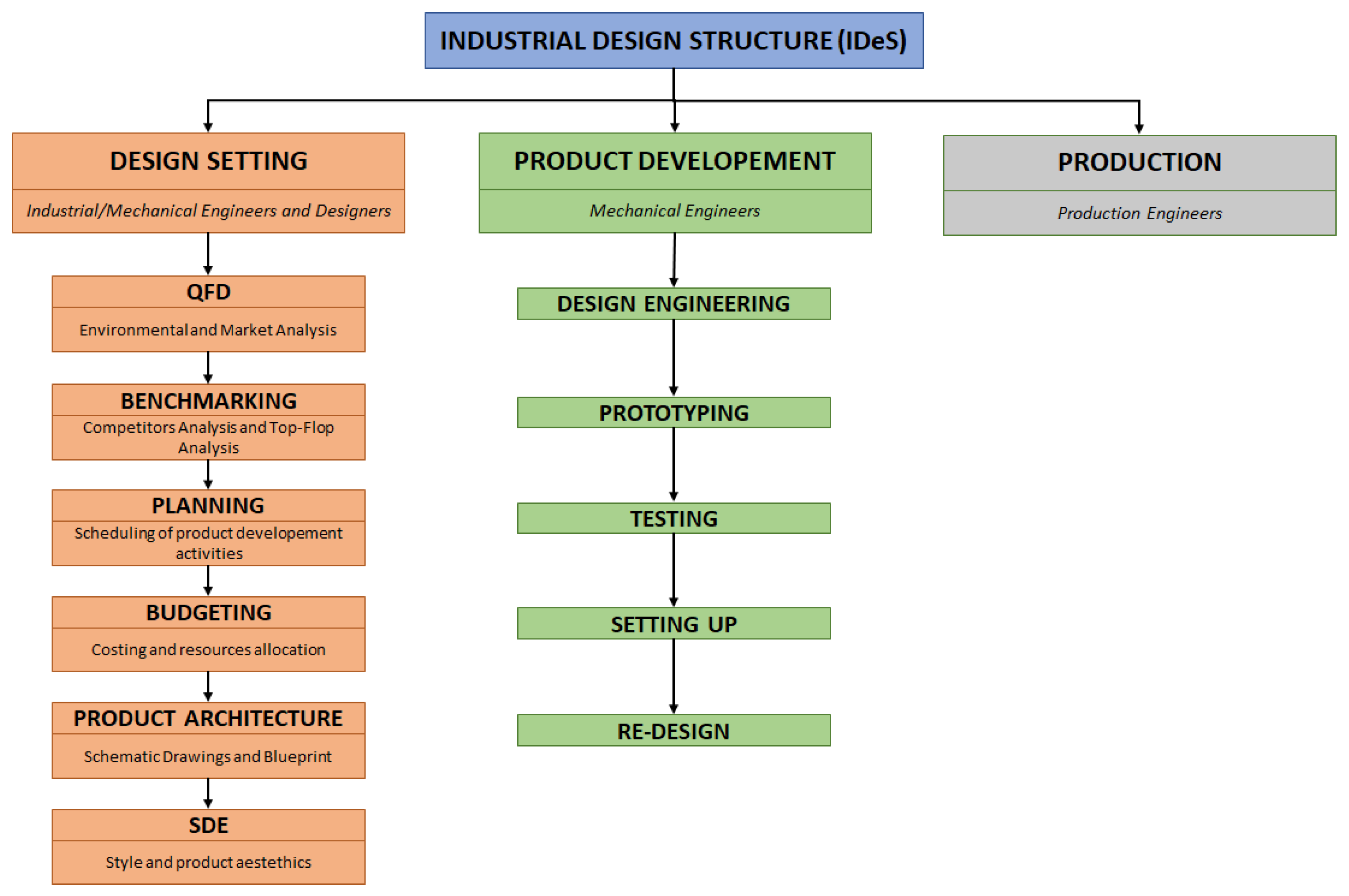
2. Materials and Methods
2.1. Environmental Analysis
2.2. Quality Function Deployment
2.2.1. Six-Questions Report
- Who uses/buy the product? As for most sports sedans, the product is intended for a middle-upper class individual, either single or with a family of a maximum of five people. The typical clients would be adult males starting from 40 years of age, employed, and having duties that require medium-to-long distance transfers. The ideal use of the car would be either for daily commutes to work or for business travel as a company vehicle. Thanks to it slick design, the car may be appealing even to people in their early 30s who are particularly interested in avant-garde technologies and have unique personalities. Families of a maximum of five people may find comfort and safety using the car for medium-short-duration travel with medium baggage. In addition, lovers of the sporty driving sensation may find the car as the golden mean between performance and pleasure. Finally, cars of this kind are also attractive in regard to the company car or taxi-limousine market.
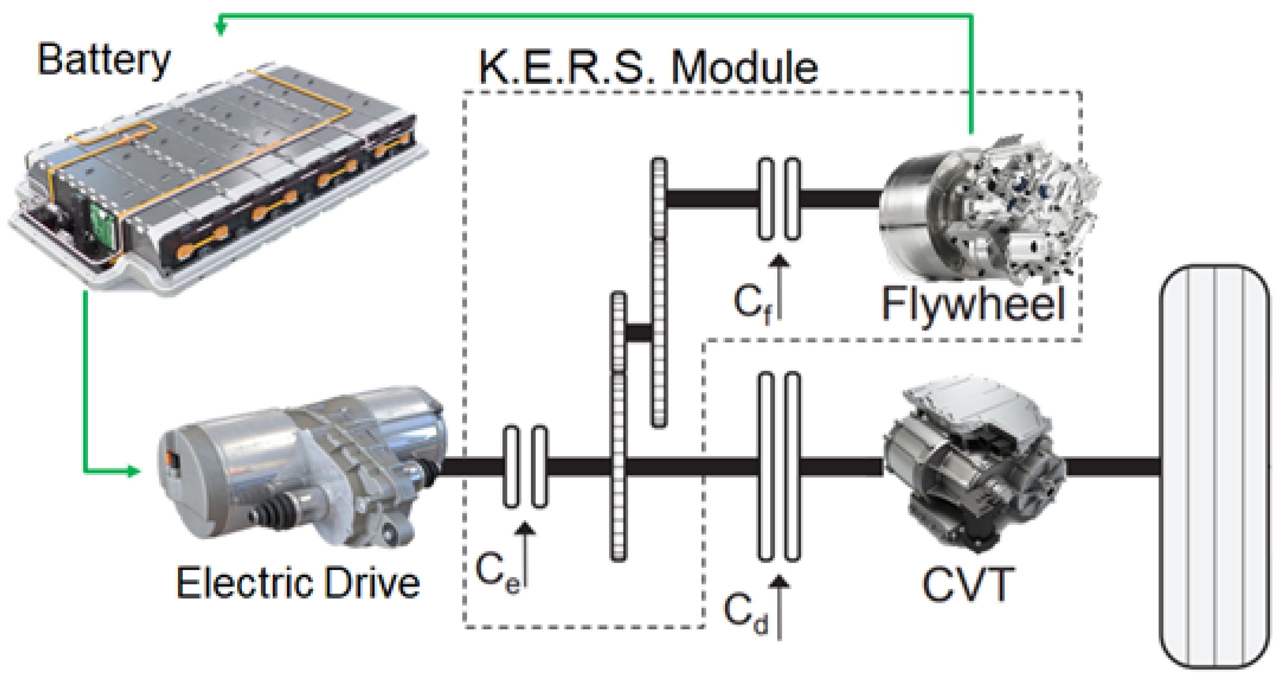
- What are the uses of the product? The product will be identifiable as an example of innovation in the automotive industry. Its cutting-edge design will have to meet the highest standards of quality and style, although not being so disruptive as to appear tacky. A particular emphasis will be directed towards providing state-of-the-art technologies for the electric powertrain in order to minimize energy consumption. An adequate battery pack shall be selected in order to acquire a range equivalent to several hours of continuous driving. Necessary in this regard is the implementation of energy recovery systems during braking. As for the interior, it will have five seats capable of comfortably sitting four people and satisfactorily sitting up to five.
- Where is the product used? The car would mainly be used outside of towns and city centres. Its dimensions and performance are the quintessential characteristics for suburban and highway driving, where high-speed cruising and low-energy consumption is needed. Moreover, in these conditions it would be ideal for the driver to be assisted by an ADAS (advanced driver-assistance system), either in the form of autonomous driving or just to improve safety. Thanks to the quiet electrical drive, the car may also be ideal for people living in low-noise and low-traffic neighbourhoods.
- When is the product used? As most modern cars, its use is predicted to be daily and remain almost constant throughout the year. A daily fast recharge of the battery pack would be ideal for long-duration daily journeys. Moreover, it should be safe to drive under all but extreme weather conditions, even when cruising at high speeds and with the ADAS engaged.
- Why would the product be chosen? The car is chosen thanks to its good overall performance, security and comfort. Its innovative and elegant design will be appealing for both middle-aged and younger customers. It will guarantee wide independence and freedom of movement to the owner without them having to fear too short ranges typical of other EVs. Finally, it is a green alternative as it will be a zero-emission vehicle and, therefore, it allows the owner to save on fuel, road tax, insurance and parking, and also allowing access to any low-traffic neighbourhoods.
- How is the product used? It can be used in a “classic” way, in which the driver enjoys the journey by being active and focused on driving the vehicle. Otherwise, in a more “futuristic” version, the driver may take advantage of the technology of autonomous driving by diverting some of their energy to socialising with other passengers or conducting business using other devices all while having the security of being in a safe environment. Finally, thanks to its performance, the driver may fully immerse in the action, taking advantage of the superior performance and driving characteristics of the vehicle.
2.2.2. Dependency Matrix
2.2.3. Importance Matrix
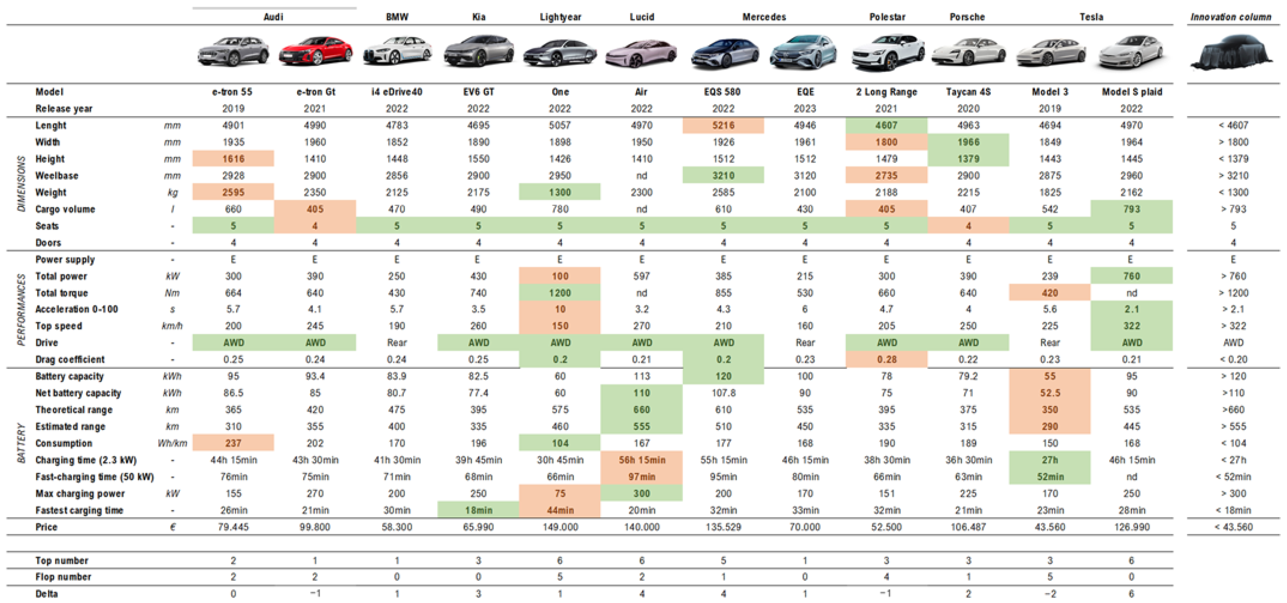
2.3. Benchmarking and Technical Requirements Definition
2.3.1. Benchmarking
2.3.2. Top-Flop Analysis
2.3.3. What-How Matrix
2.4. Product Architecture
2.4.1. 2D Architecture
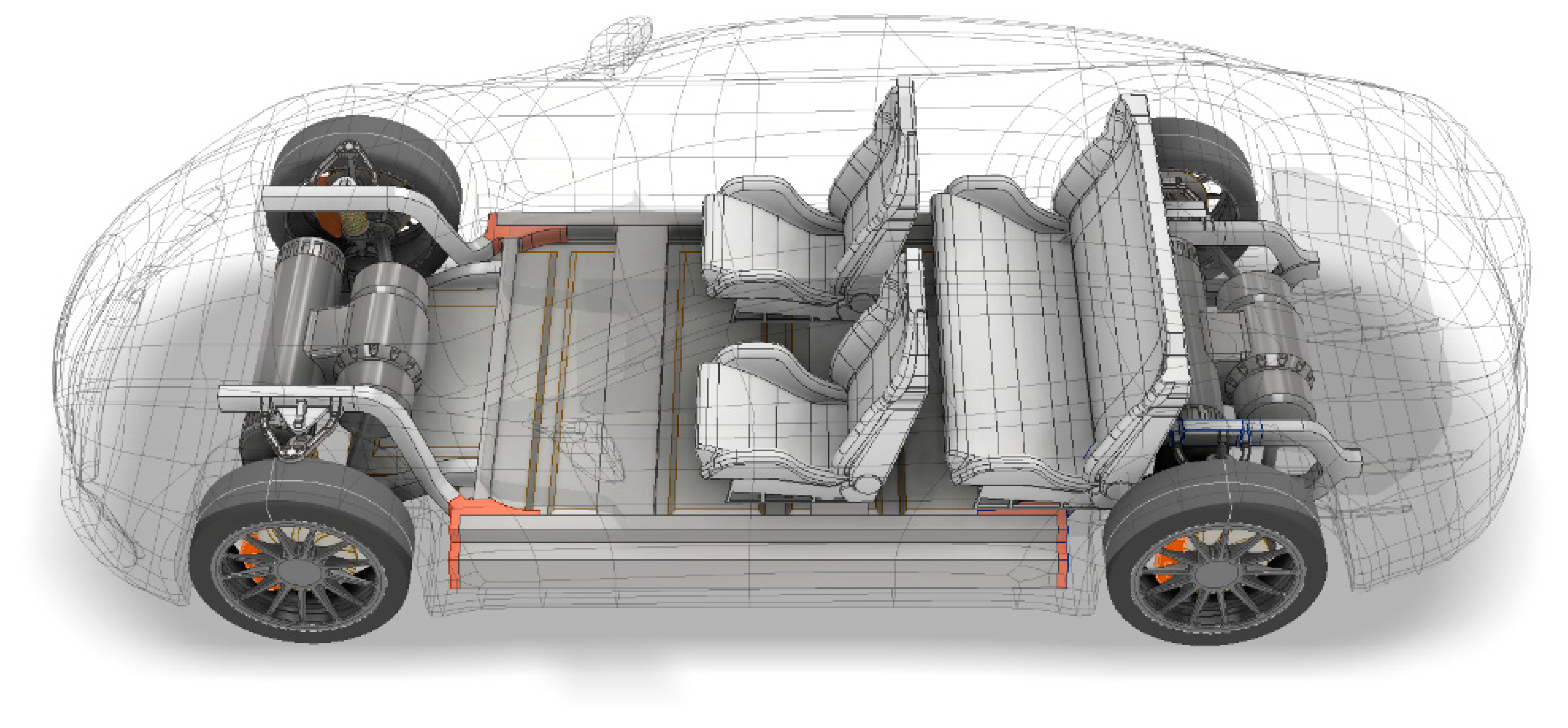
2.4.2. 3D Architecture
2.5. Stylistic Design Engineering
2.5.1. Stylistic Trend Analysis
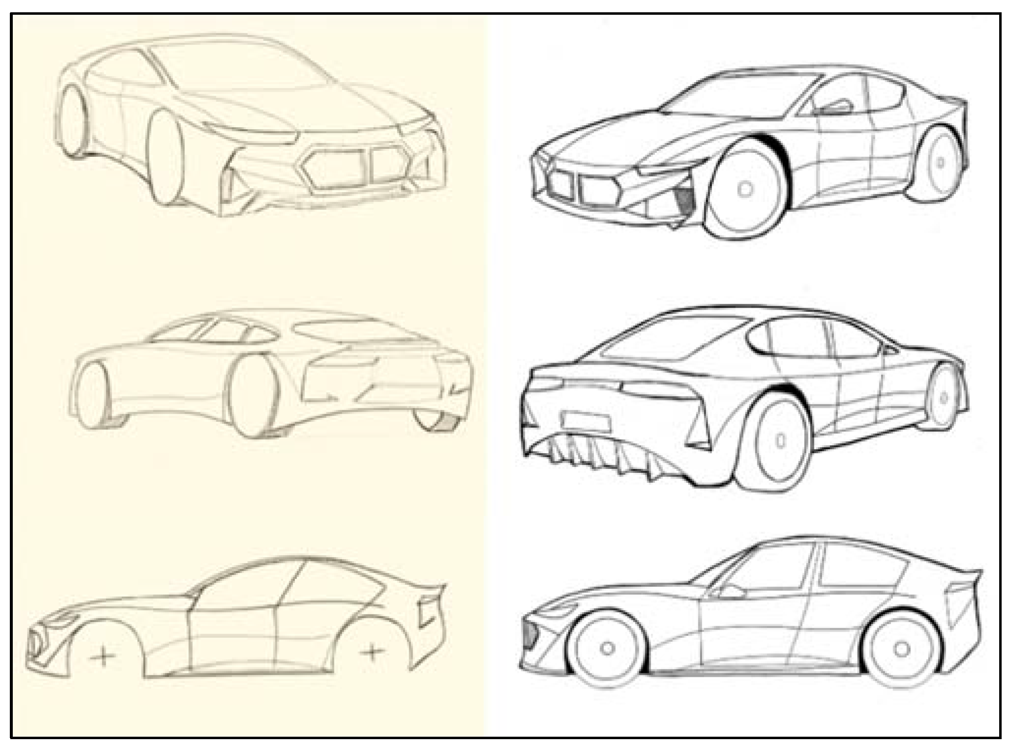
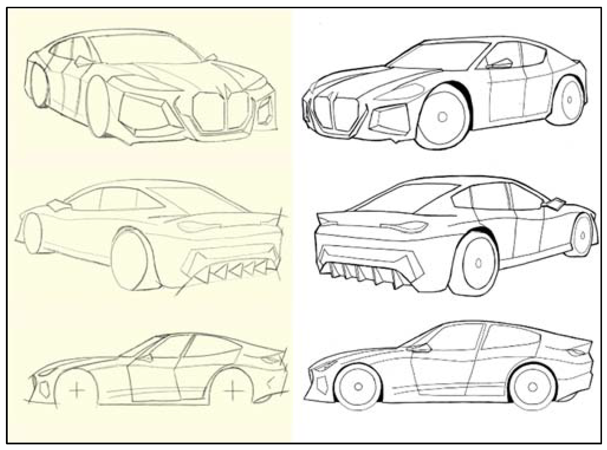
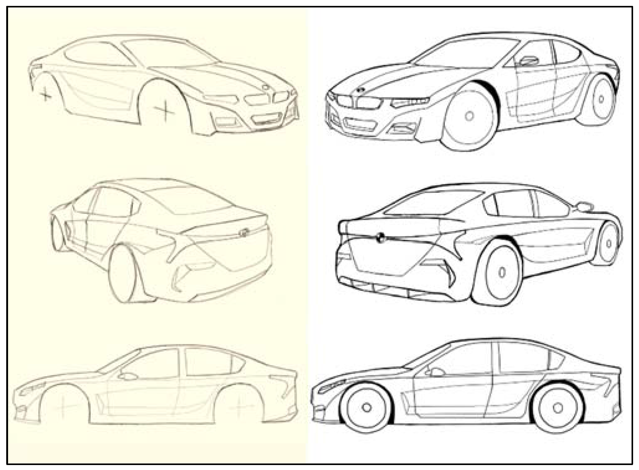
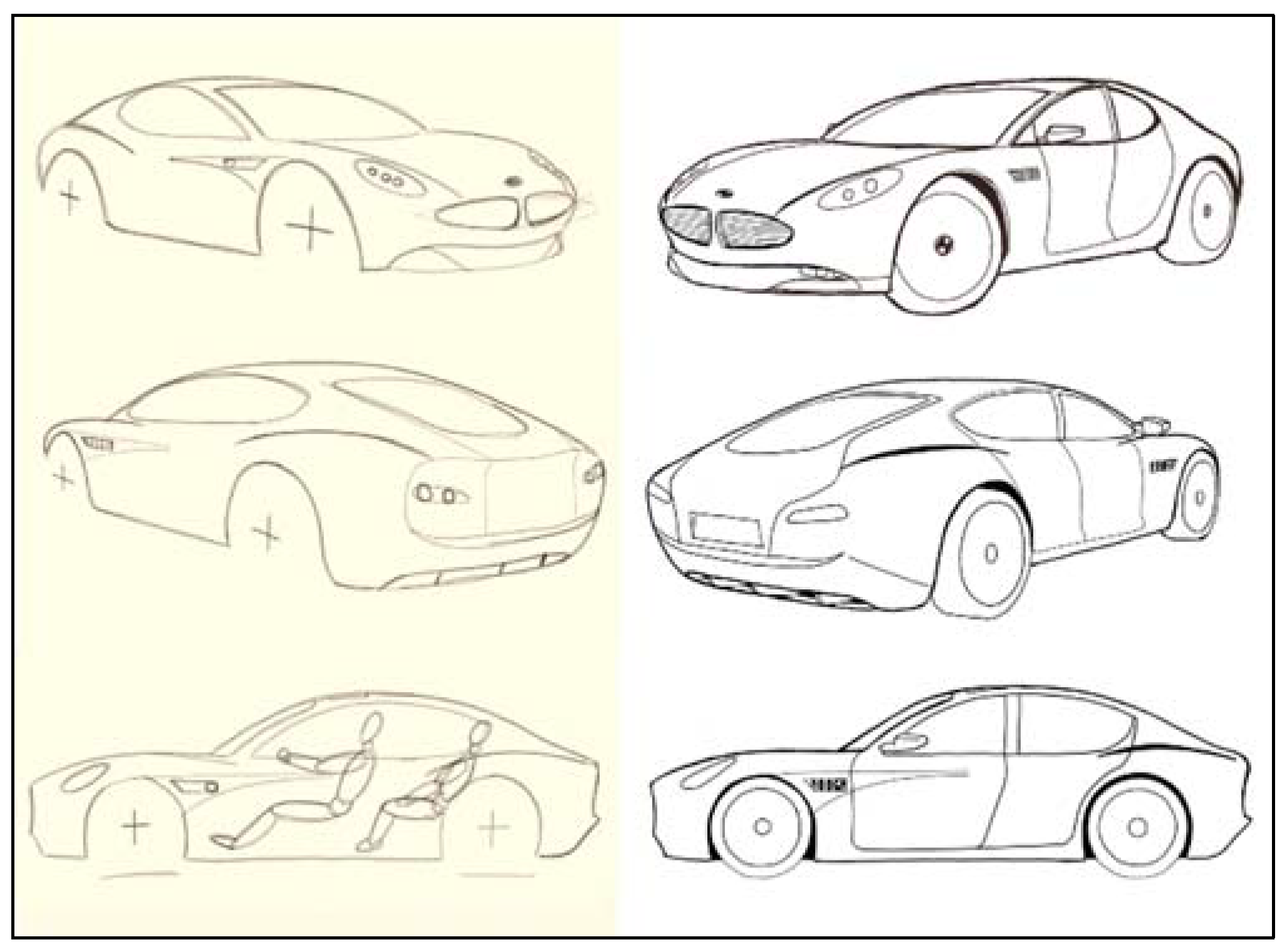
2.5.2. Sketching
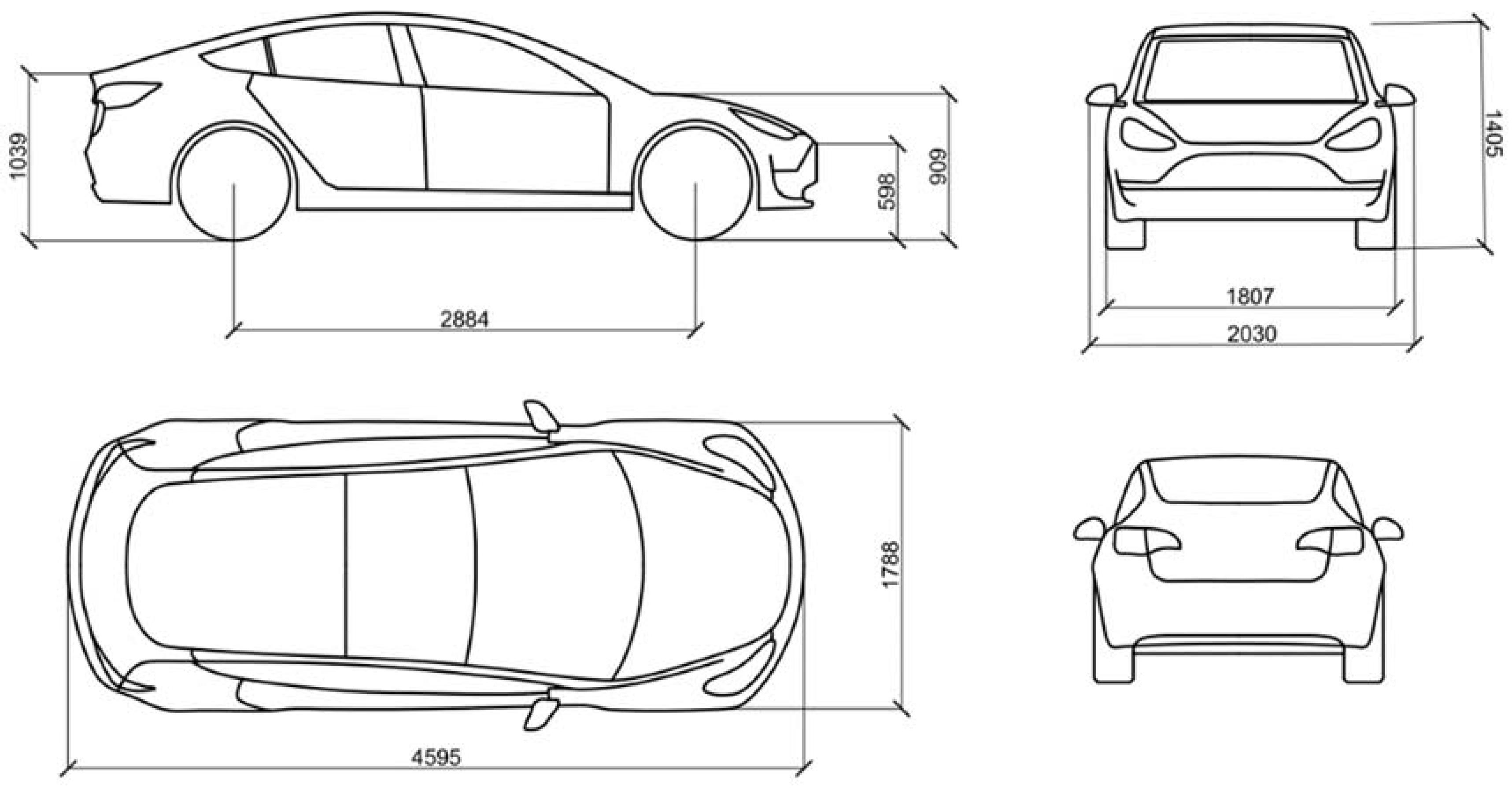
2.6. Product Development: Design Engineering
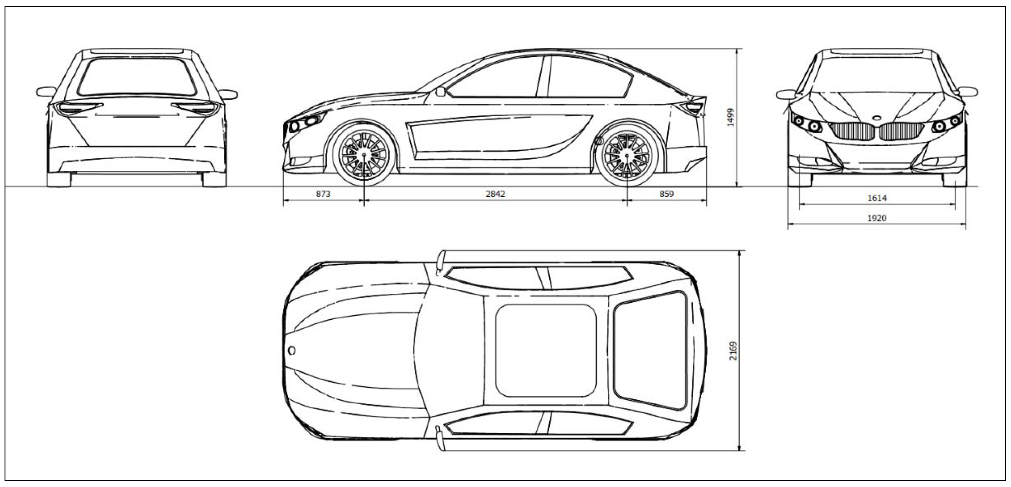
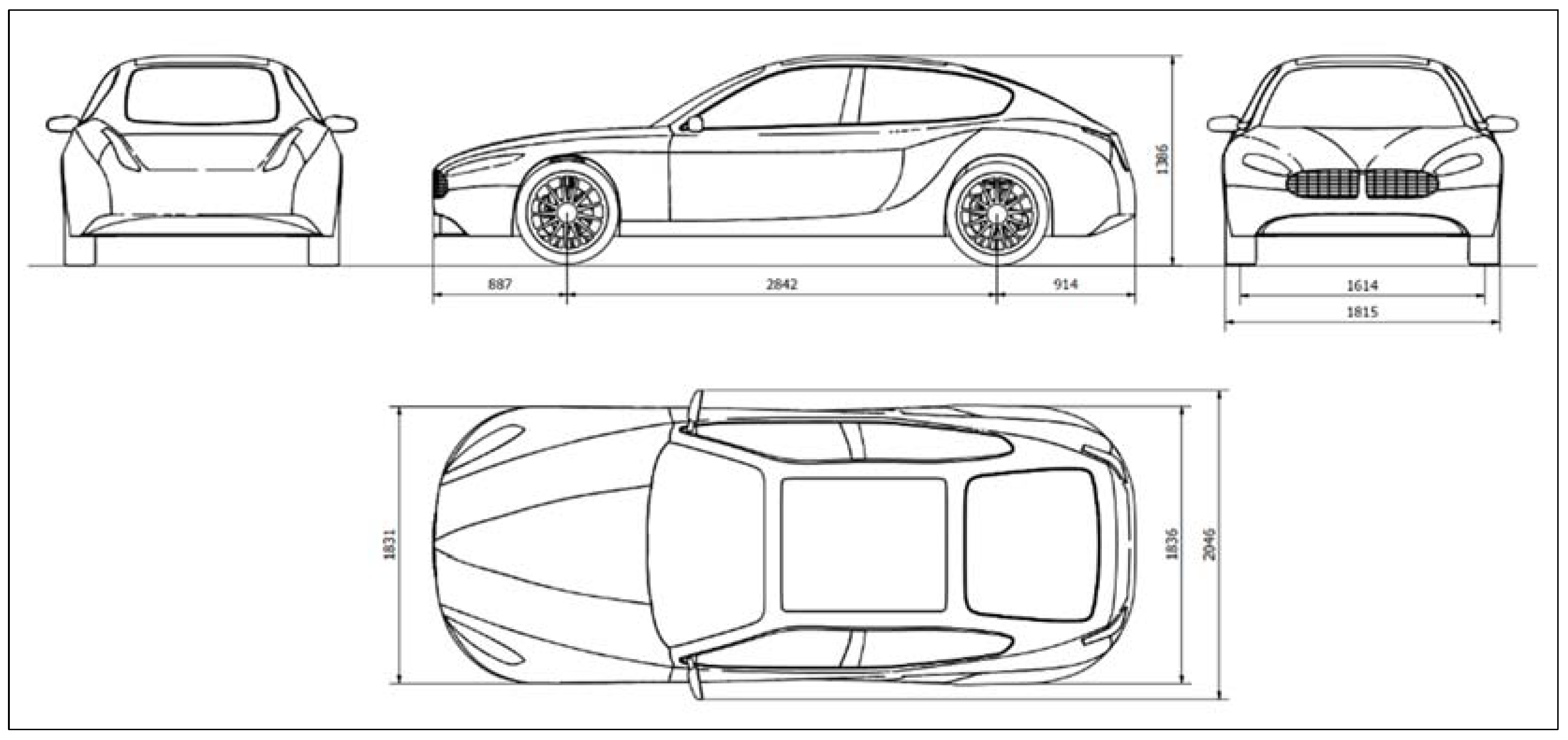
2.6.1. Orthogonal Drawings
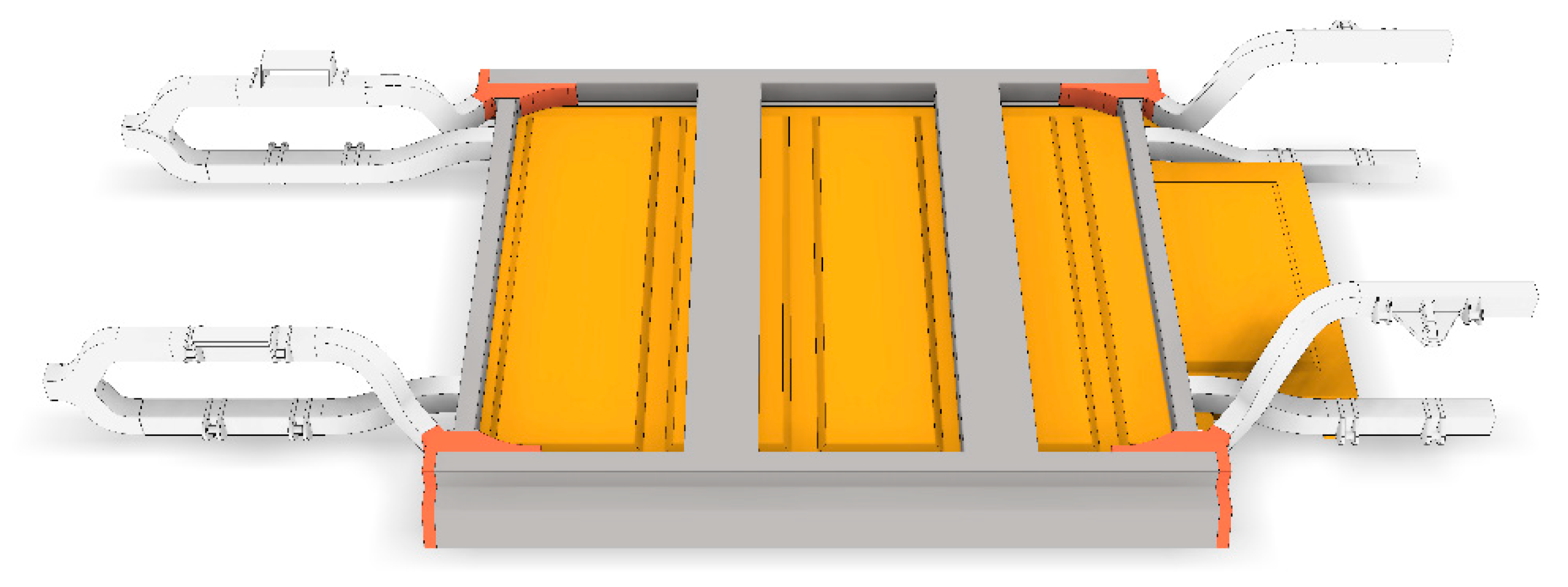
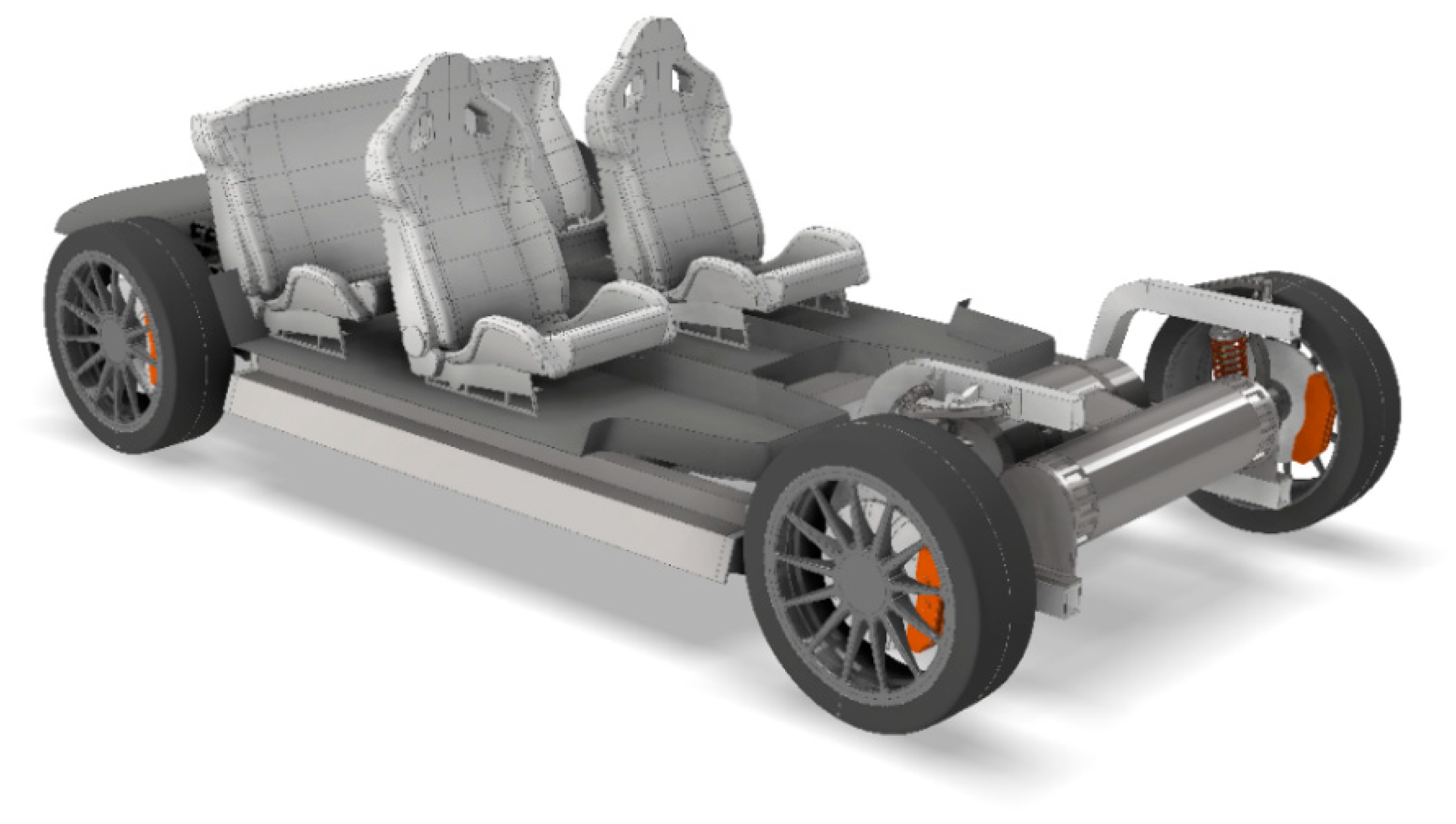
2.6.2. Chassis Modelling
- -
- Space Frame: It consists of a framework of beams connected at nodes in a truss structure. Usually, the process used in order to produce this kind of body structure is roll forming and hydro-form, ideal for low production volumes.
- -
- Ladder Chassis: It consists of two longitudinal beams connected by a series of transverse struts. This chassis structure has the advantages of easy manufacturing and low price. On the other hand, not being a three-dimensional structure reduces torsional stiffness of the vehicle. The vehicles that adopt this kind of chassis are usually referred to as adopting a body-on-frame architecture.
- -
- Central close tunnel: It is similar to the ladder chassis except for the fact that the structural integrity of the vehicle lies in a singular large member running down the centre of the vehicle. This kind of architecture has the problem of limiting the overall size of the vehicle.
- -
- Integral Frame: This chassis type consists of one main strong structure that integrates both frame and body. This solution offers high resistance to loads. Other advantages include space saving and weight reduction. Minimizing wasted material and production processes are valid reasons for mass production.
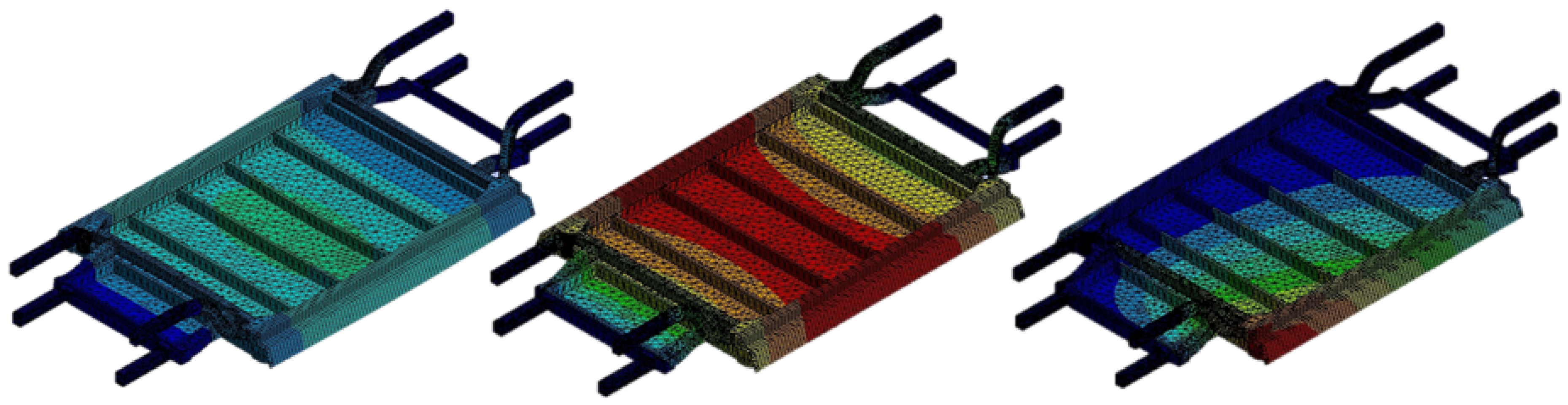
2.6.3. FEM Analysis and Optimization
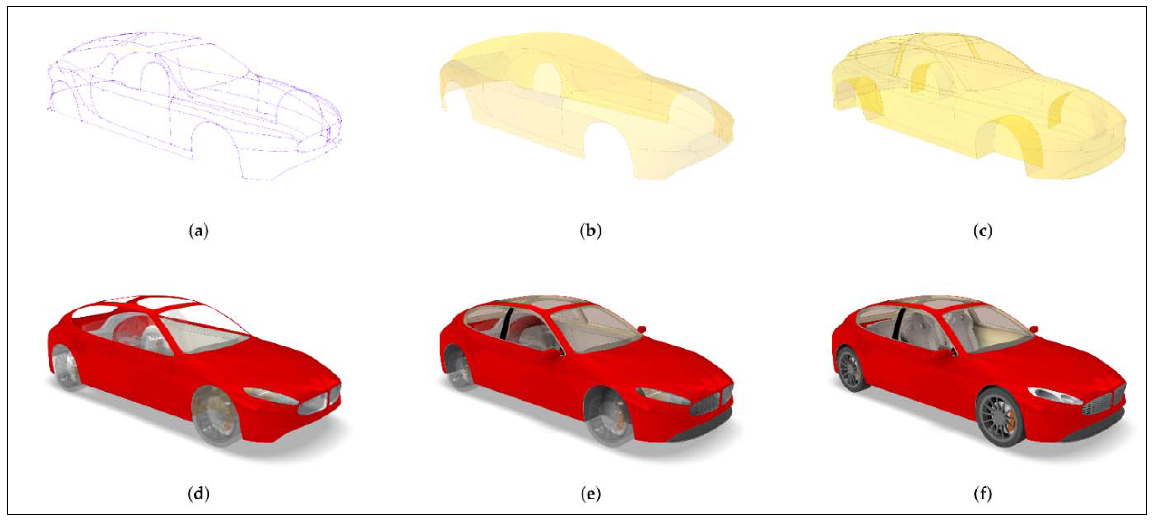
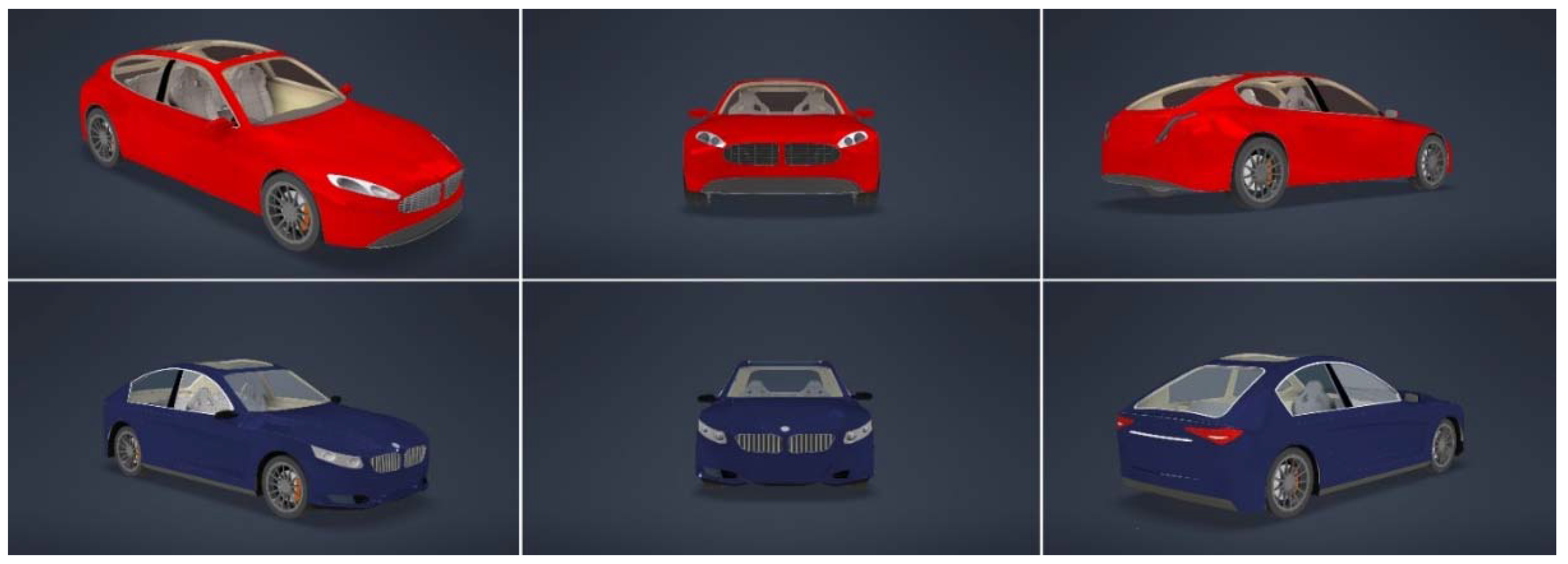
2.6.4. Surface Modelling
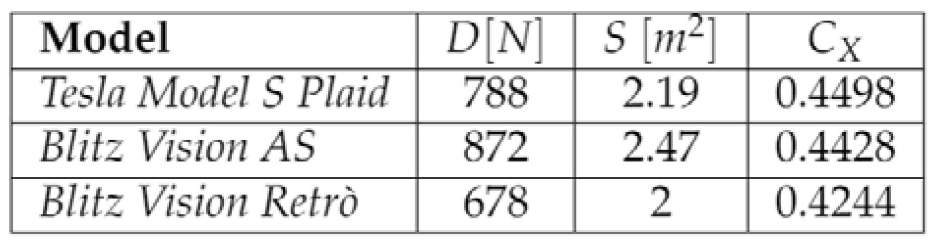
2.6.5. CFD Analysis and Optimization
2.7. Prototyping
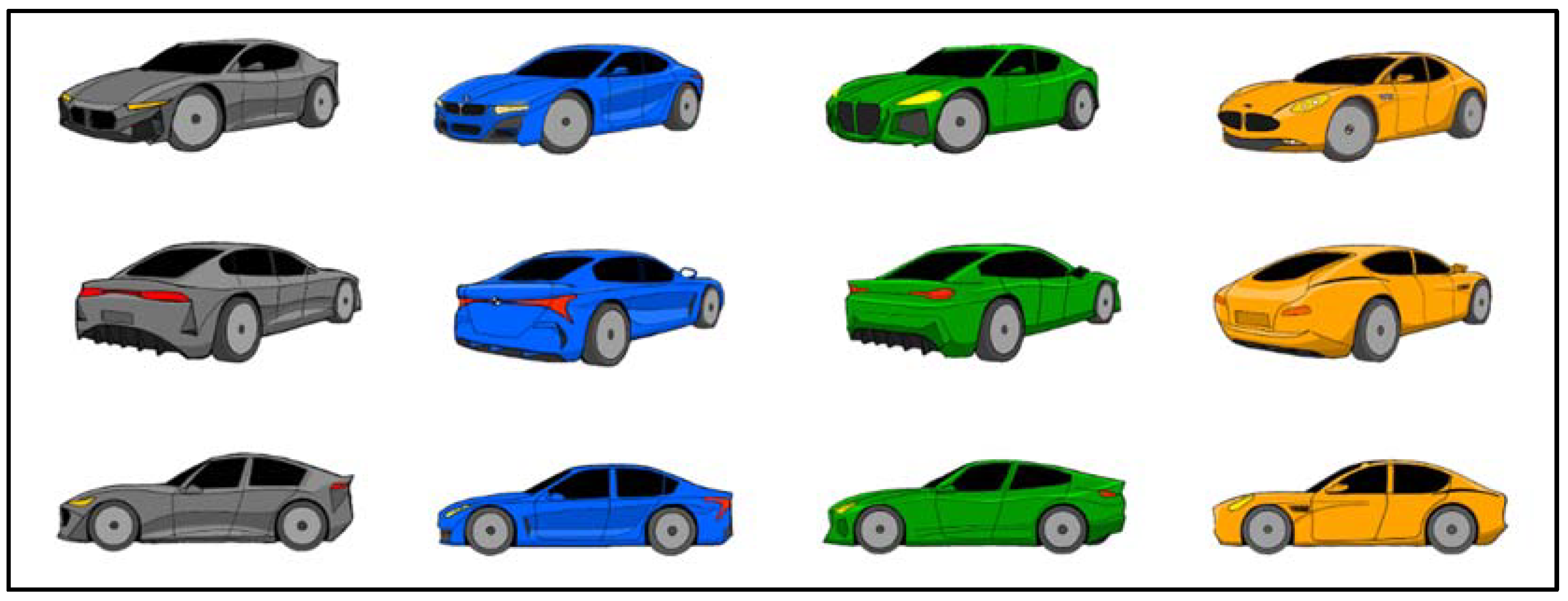
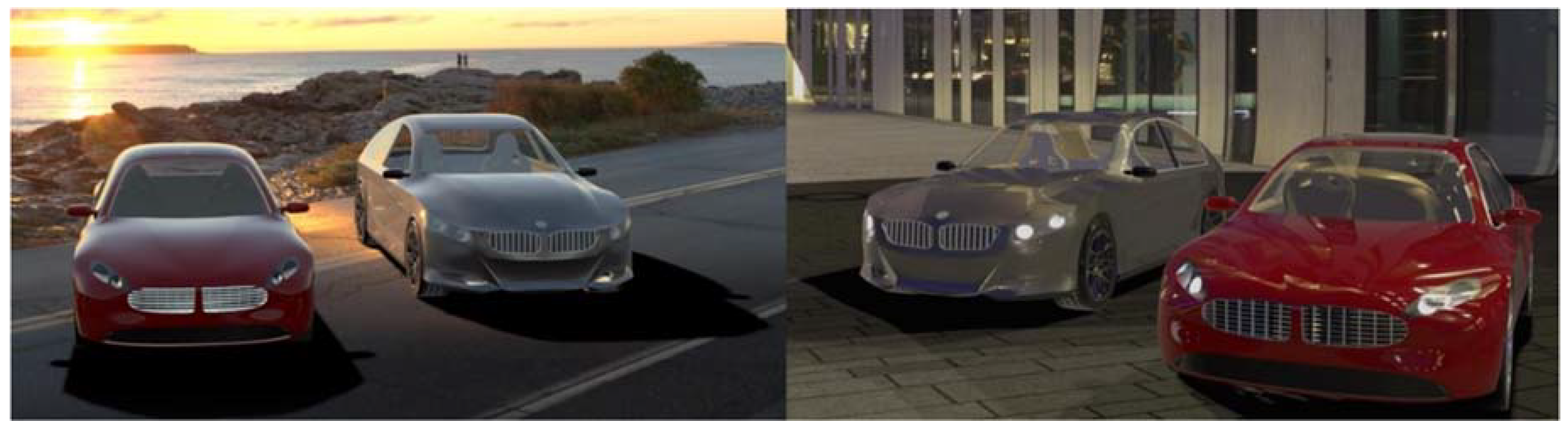
2.7.1. Rendering
2.7.2. Augmented Reality
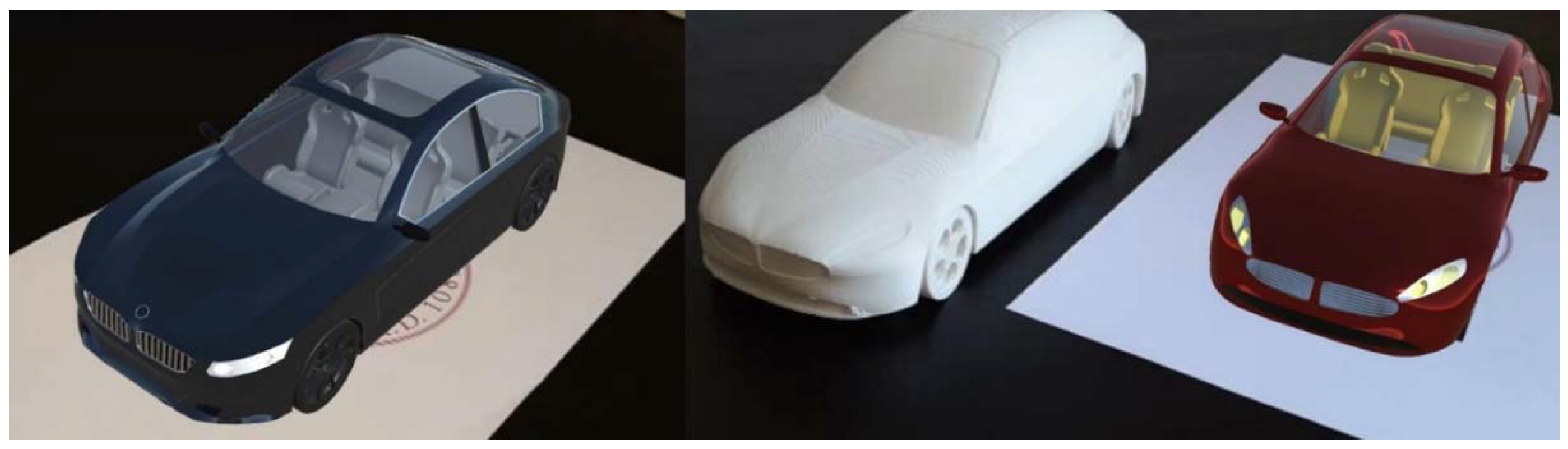
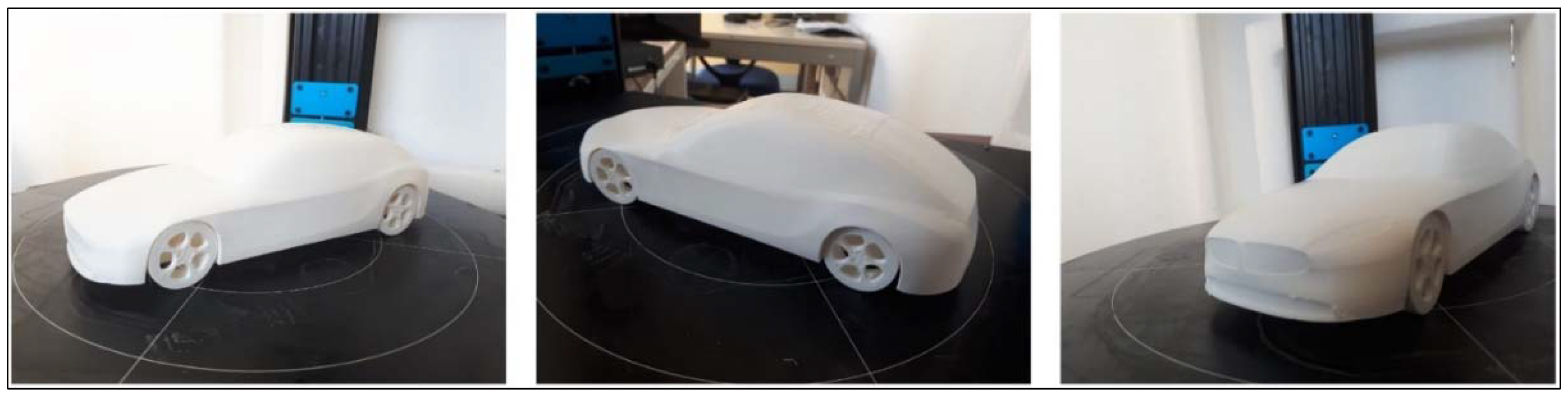
2.7.3. Solid Stylistic Model (Maquette)
3. Results
4. Discussion
5. Future Developments
6. Conclusions
- -
- A thorough and complete analysis of the stylistic trends dominating the sports sedan market.
- -
- Two innovative stylistic proposals for new BMW sports sedans using digital sketching techniques.
- -
- CAD modelling and FEM validation of the modular platform-chassis.
- -
- Surface modelling of the vehicle and validation via CFD analysis.
- -
- Augmented reality application for both proposals.
- -
- A solid model (maquette) produced via additive manufacturing (AM).
Author Contributions
Funding
Institutional Review Board Statement
Informed Consent Statement
Data Availability Statement
Conflicts of Interest
References
- Xu, Q.; Jiao, R.J.; Yang, X.; Helander, M.; Khalid, H.M.; Opperud, A. An analytical Kano model for customer need analysis. Des. Stud. 2008, 30, 87–110. [Google Scholar] [CrossRef]
- Mikulić, J.; Prebežac, D. A critical review of techniques for classifying quality attributes in the Kano model. Manag. Serv. Qual. Int. J. 2011, 21, 46–66. [Google Scholar] [CrossRef] [Green Version]
- Lipparini, A. Economia e Gestione Delle Imprese; Il Mulino: Bologna, Italy, 2007. [Google Scholar]
- Khan, K. An Overview on Taguchi Method. Available online: https://www.researchgate.net/publication/265282800 (accessed on 3 March 2022).
- Antony, J. Teaching the Taguchi method to industrial engineers. Work Study 2001, 50, 141–149. [Google Scholar] [CrossRef]
- Tsui, K.L. An overview of Taguchi method and newly developed statistical methods for robust design. IIE Trans. 1992, 24, 44–57. [Google Scholar] [CrossRef]
- Ginting, R.; Ishak, A.; Malik, A.F.; Satrio, M.R. Product Development with Quality Function Deployment (QFD): A Literature Review. IOP Conf. Ser. Mater. Sci. Eng. 2020, 1003, 012022. [Google Scholar] [CrossRef]
- Elhegazy, H.; Ebid, A.; Mahdi, I.; Haggag, S.; Abdul-Rashied, I. Implementing QFD in decision making for selecting the optimal structural system for buildings. Constr. Innov. 2020, 21, 345–360. [Google Scholar] [CrossRef]
- Cristiano, J.J.; Liker, J.K.; White, C.C. Key factors in the successful application of quality function deployment (QFD). IEEE Trans. Eng. Manag. 2001, 48, 81–95. [Google Scholar] [CrossRef]
- Bañuelas, R.; Antony, J. Six sigma or design for six sigma? TQM Mag. 2004, 16, 250–263. [Google Scholar] [CrossRef]
- Yang, K.; El-Haik, B.S. Design for Six Sigma: A Roadmap for Product Development; McGraw-Hill Education: New York, NY, USA, 2009; Available online: https://www.accessengineeringlibrary.com/content/book/9780071547673 (accessed on 3 March 2022).
- THE FUTURE OF AUTOMOTIVE A Survey of Auto Manufacturing Decision Makers Molex Confidential Information. Available online: https://experience.molex.com/webfoo/wp-content/uploads/2020/12/the-future-of-automotive.pdf (accessed on 15 March 2022).
- Kusiak, A. Innovation: The Living Laboratory Perspective. Comput.-Aided Des. Appl. 2013, 4, 863–876. [Google Scholar] [CrossRef]
- Schmitz, K.; Hoppe, W.-D.; Little, A.D. Uncertain drivers take global automotive markets to a crossroads. Global Automotive Mobility Study—3rd Edition: The Future of Automotive Mobility Content. 2018. Available online: https://www.adlittle.com/sites/default/files/reports/ADL_The_future_of_automotive_mobility.pdf (accessed on 18 March 2022).
- Katzenbach, A. Automotive. In Concurrent Engineering in the 21st Century: Foundations, Developments and Challenges; Springer: Berlin/Heidelberg, Germany, 2015; pp. 607–638. [Google Scholar] [CrossRef]
- Eberle, U.; von Helmolt, R. Sustainable transportation based on electric vehicle concepts: A brief overview. Energy Environ. Sci. 2010, 3, 689–699. [Google Scholar] [CrossRef]
- Global EV Outlook 2021—Analysis—IEA. Available online: https://www.iea.org/reports/global-ev-outlook-2021 (accessed on 15 March 2022).
- Wolniak, R. The history of the QFD method. Sci. Pap. Silesian Univ. Technol. Organ. Manag. Ser. 2017, 2017, 553–564. [Google Scholar] [CrossRef]
- Delbridge, R.; Lowe, J.; Oliver, N. The process of benchmarking: A study from the automotive industry. Int. J. Oper. Prod. Manag. 1995, 15, 50–62. [Google Scholar] [CrossRef]
- Panwar, A.; Nepal, B.; Jain, R.; Yadav, O.P. Implementation of benchmarking concepts in Indian automobile industry—An empirical study. Benchmarking Int. J. 2013, 20, 777–804. [Google Scholar] [CrossRef]
- Xie, G.; Chen, Y.; Liu, Y.; Li, R.; Li, K. Minimizing Development Cost with Reliability Goal for Automotive Functional Safety during Design Phase. IEEE Trans. Reliab. 2018, 67, 196–211. [Google Scholar] [CrossRef]
- Sarmento, A.; Pereira, A.L.J.; Barbieri, C.A.; Sakuramoto, C. Body Structure Contribution for Automotive Energy Efficiency Improvement—INOVAR Auto Program; SAE Technical Paper; SAE International: Warrendale, PA, USA, 2013. [Google Scholar] [CrossRef]
- Li, J.; Fu, L. On the BMW auto-body styling design based on automobile brand characteristics. In Proceedings of the International Conference on Transportation, Mechanical, and Electrical Engineering (TMEE 2011), Changchun, China, 16–18 December 2011; pp. 1261–1264. [Google Scholar] [CrossRef]
- Zhu, Y.F. An Evolution Study on Family Characteristic of BMW 3 Series Based on Aerodynamics. Appl. Mech. Mater. 2012, 184–185, 45–48. [Google Scholar] [CrossRef]
- Tovey, M.; Porter, S.; Newman, R. Sketching, concept development and automotive design. Des. Stud. 2002, 24, 135–153. [Google Scholar] [CrossRef]
- Pache, M.; Lindemann, U. Sketching in 3D What Should Future Tools for Conceptual Design Look Like? Springer: Berlin/Heidelberg, Germany, 2003; pp. 243–252. [Google Scholar] [CrossRef]


| Six Questions | Key Elements |
|---|---|
| Who uses/buy the product? | Comfort, Design, Medium price, Safety |
| What are the uses of the product? | Comfort, Design, Electric drive, Low consumption, Energy recovery systems, Performances, Safety |
| Where is the product used? | ADAS, Electric drive, Low consumption, Performances |
| When is the product used? | ADAS, Electric drive, Fast recharge |
| Why would it be chosen? | Comfort, Design, Eco-friendliness, Performances |
| How is the product used? | ADAS, Connectivity, Performances, Safety |
| Value | Dependency Judgement |
|---|---|
| Empty | No dependency between the two requirements |
| 1 | Weak dependency between the two requirements |
| 3 | Medium dependency between the two requirements |
| 9 | Strong dependency between the two requirements |
| Dependence Matrix | Price | Performances | Comfort | Electrification | Safety | Design | Efficiency | Low Consumption | ADAS | Fastrecharge | Eco Friendliness | Connectivity | Total |
|---|---|---|---|---|---|---|---|---|---|---|---|---|---|
| Price | 9 | 3 | 9 | 1 | 1 | 3 | 3 | 1 | 9 | 39 | |||
| Performances | 9 | 3 | 3 | 9 | 24 | ||||||||
| Comfort | 3 | 1 | 9 | 3 | 16 | ||||||||
| Electrification | 3 | 9 | 9 | 9 | 3 | 33 | |||||||
| Safety | 1 | 3 | 1 | 9 | 3 | 17 | |||||||
| Design | 3 | 3 | 3 | 3 | 12 | ||||||||
| Efficiency | 1 | 3 | 3 | 7 | |||||||||
| Low consumption | 9 | 9 | 3 | 1 | 3 | 3 | 28 | ||||||
| ADAS | 1 | 3 | 1 | 3 | 9 | 17 | |||||||
| Fast recharge | 3 | 9 | 3 | 1 | 16 | ||||||||
| Eco-friendliness | 1 | 1 | 9 | 3 | 9 | 3 | 1 | 27 | |||||
| Connectivity | 1 | 9 | 10 | ||||||||||
| Total | 23 | 21 | 13 | 44 | 7 | 5 | 18 | 33 | 30 | 13 | 7 | 32 |
| Value | Importance |
|---|---|
| 0 | The row item is less important than the column item |
| 1 | The row item and the column item have equal importance |
| 2 | The row item is more important than the column item |
| Importance Matrix | Price | Performances | Comfort | Electrification | Safety | Design | Efficiency | Low Consumption | ADAS | Fast Recharge | Eco Friendliness | Connectivity | Total | Importance |
|---|---|---|---|---|---|---|---|---|---|---|---|---|---|---|
| Price | 1 | 2 | 1 | 1 | 1 | 2 | 1 | 1 | 2 | 1 | 1 | 2 | 16 | 7.6 |
| Performances | 0 | 1 | 0 | 0 | 0 | 1 | 2 | 2 | 1 | 2 | 2 | 1 | 12 | 5.7 |
| Comfort | 1 | 2 | 1 | 1 | 1 | 2 | 1 | 0 | 2 | 1 | 1 | 2 | 15 | 7.1 |
| Electrification | 1 | 2 | 1 | 1 | 0 | 2 | 1 | 1 | 2 | 1 | 1 | 2 | 15 | 7.1 |
| Safety | 1 | 2 | 1 | 2 | 1 | 2 | 2 | 2 | 2 | 2 | 2 | 2 | 21 | 10.0 |
| Design | 0 | 1 | 0 | 0 | 0 | 1 | 0 | 0 | 1 | 0 | 0 | 1 | 4 | 1.9 |
| Efficiency | 1 | 0 | 1 | 1 | 0 | 2 | 1 | 1 | 2 | 1 | 1 | 2 | 13 | 6.2 |
| Low consumption | 1 | 0 | 2 | 1 | 0 | 2 | 1 | 1 | 2 | 1 | 1 | 2 | 14 | 6.7 |
| ADAS | 0 | 1 | 0 | 0 | 0 | 1 | 0 | 0 | 1 | 0 | 0 | 1 | 4 | 1.9 |
| Fast recharge | 1 | 0 | 1 | 1 | 0 | 2 | 1 | 1 | 2 | 1 | 1 | 2 | 13 | 6.2 |
| Eco-friendliness | 1 | 0 | 1 | 1 | 0 | 2 | 1 | 1 | 2 | 1 | 1 | 2 | 13 | 6.2 |
| Connectivity | 0 | 1 | 0 | 0 | 0 | 1 | 0 | 0 | 1 | 0 | 0 | 1 | 4 | 1.9 |
| What-How Matrix | Length | Width | Height | Wheelbase | Weight | Cargo Volume | Power Supply | Total Power | Total Torque | Acceleration 0–100 | Top Speed | Drive | Drag Coefficient | Battery Usable | Theoretical Range | Consumption | Max Charging Power | Fastest Charging Time | Price | Total |
|---|---|---|---|---|---|---|---|---|---|---|---|---|---|---|---|---|---|---|---|---|
| Price | 1 | 1 | 1 | 1 | 9 | 9 | 9 | 3 | 3 | 3 | 1 | 9 | 3 | 1 | 1 | 9 | 64 | |||
| Comfort | 9 | 9 | 9 | 9 | 3 | 9 | 1 | 1 | 1 | 1 | 3 | 9 | 9 | 9 | 3 | 85 | ||||
| Electrification | 9 | 9 | 9 | 9 | 3 | 3 | 3 | 45 | ||||||||||||
| Safety | 3 | 3 | 3 | 3 | 3 | 3 | 18 | |||||||||||||
| Efficiency | 9 | 1 | 9 | 3 | 3 | 3 | 3 | 3 | 9 | 1 | 3 | 9 | 1 | 1 | 58 | |||||
| Low Consumption | 3 | 9 | 3 | 3 | 3 | 3 | 9 | 3 | 9 | 9 | 3 | 3 | 60 | |||||||
| Fast Recharge | 9 | 3 | 3 | 9 | 9 | 1 | 34 | |||||||||||||
| Eco Friendliness | 1 | 9 | 1 | 1 | 1 | 1 | 3 | 3 | 9 | 1 | 1 | 1 | 32 | |||||||
| Total | 13 | 13 | 13 | 13 | 19 | 10 | 55 | 17 | 17 | 11 | 10 | 9 | 19 | 28 | 39 | 36 | 27 | 27 | 20 |
Publisher’s Note: MDPI stays neutral with regard to jurisdictional claims in published maps and institutional affiliations. |
© 2022 by the authors. Licensee MDPI, Basel, Switzerland. This article is an open access article distributed under the terms and conditions of the Creative Commons Attribution (CC BY) license (https://creativecommons.org/licenses/by/4.0/).
Share and Cite
Frizziero, L.; Galletti, L.; Magnani, L.; Meazza, E.G.; Freddi, M. Blitz Vision: Development of a New Full-Electric Sports Sedan Using QFD, SDE and Virtual Prototyping. Inventions 2022, 7, 41. https://doi.org/10.3390/inventions7020041
Frizziero L, Galletti L, Magnani L, Meazza EG, Freddi M. Blitz Vision: Development of a New Full-Electric Sports Sedan Using QFD, SDE and Virtual Prototyping. Inventions. 2022; 7(2):41. https://doi.org/10.3390/inventions7020041
Chicago/Turabian StyleFrizziero, Leonardo, Ludovico Galletti, Lorenzo Magnani, Edoardo Gaetano Meazza, and Marco Freddi. 2022. "Blitz Vision: Development of a New Full-Electric Sports Sedan Using QFD, SDE and Virtual Prototyping" Inventions 7, no. 2: 41. https://doi.org/10.3390/inventions7020041