Review

The Latest Advances in Wireless Communication in Aviation, Wind Turbines and Bridges

1
Faculty of Mechanical Engineering and Aeronautics, Rzeszow University of Technology, 35-959 Rzeszow, Poland
2
Faculty of Electrical and Computer Engineering, Rzeszow University of Technology, 35-959 Rzeszow, Poland
3
Faculty of Civil and Environmental Engineering and Architecture, Rzeszow University of Technology, 35-959 Rzeszow, Poland
4
Aerodynamics Department, Institute of Fluid-Flow Machinery Polish Academy of Sciences, 80-231 Gdansk, Poland
5
Faculty of Mechanical Engineering and Ship Technology, Gdansk University of Technology, 80-233 Gdansk, Poland
6
Cardiff University School of Engineering, Cardiff CF24 3AA, UK
7
School of Engineering and Natural Sciences, University of Iceland, 107 Reykjavlk, Iceland
*
Author to whom correspondence should be addressed.
Inventions 2022, 7(1), 18; https://doi.org/10.3390/inventions7010018
Submission received: 11 December 2021 / Revised: 13 January 2022 / Accepted: 24 January 2022 / Published: 29 January 2022
(This article belongs to the Collection Feature Innovation Papers)

Abstract

:
Present-day technologies used in SHM (Structural Health Monitoring) systems in many implementations are based on wireless sensor networks (WSN). In the context of the continuous development of these systems, the costs of the elements that form the monitoring system are decreasing. In this situation, the challenge is to select the optimal number of sensors and the network architecture, depending on the wireless system’s other parameters and requirements. It is a challenging task for WSN to provide scalability to cover a large area, fault tolerance, transmission reliability, and energy efficiency when no events are detected. In this article, fundamental issues concerning wireless communication in structural health monitoring systems (SHM) in the context of non-destructive testing sensors (NDT) were presented. Wireless technology developments in several crucial areas were also presented, and these include engineering facilities such as aviation and wind turbine systems as well as bridges and associated engineering facilities.

1. Introduction

The implementation and development of wireless communication for unlocking the potential of SHM systems in aerospace, bridge structures, and wind turbines seems to be an essential and most urgent research problem as well as a technical one. In recent years, wireless communications have been used as a preferred as well as reliable data transmission means in a number of aerospace applications, the flight-critical ones included. The aerospace industry ought to consider the substitution of some aerial-vehicle sensor wiring with wireless communications; the related sensors are also known as aerospace wireless sensors (AWSs). Wireless communication solves many problems for aero-engines: cabling, maintenance, health monitoring, and problem diagnosis. It is essential to take into account wireless communication through metals (wave propagations), powering remote sensors and managing power (inductive coupling method, solution architecture) and electronics in a harsh environment. The importance of Wireless Avionics Intra-Communications is demonstrated as radiocommunication between avionics components integrated or installed onboard one and the same aircraft, radiocommunication in an exclusive closed network between two or more points on a single aircraft and covers only safety and regularity of flight-related applications. There are a lot of issues that the aviation industry has to deal with, and they include, to name but a few: how to reduce the complexity of electrical wiring and harness fabrication with simultaneous weight saving and higher overall fuel efficiency, how to significantly enhance reconfigurability through improved installation flexibility e.g., for cabin elements, how to reliably monitor parameters belonging to moving or rotating parts or improve reliability of aircraft systems through mitigation of common-mode failures by the application of dissimilar redundancy.
Wireless technology for Bridge Health Monitoring as Structural health monitoring (also know as SHM) systems have revealed a huge potential to capture a bridge system’s responses, diagnose the current structural conditions, predict the expected future performance, and provide information for the maintenance validate design hypotheses. Wireless sensor networks (known as WSNs) which have the advantages of reducing the costs concerning the implementation of SHM systems and enhancing data processing efficiency have become an attractive option for traditional tethered sensor systems.
This article discusses wireless communication, wireless communication types, including their main benefits and existing limitations and risks. In particular, wireless technologies have been considered in terms of their applicability in WSN (Wireless Sensor Networks), SHM (Structural Health Monitoring), and communication of the main subsystems in aircraft—ASN (Avionics Sensor Network) and WAN (Wireless Avionics Network).
A Wireless Sensor Network for wind energy sector, with particular focus on wind turbines, should be considered mainly for large output on-shore and off-shore turbines, which may be regarded as a single turbine’s point of view. The primary system for data acquisition for the monitoring of wind turbine operation is the SCADA system. SCADA data for a wind turbine or wind farms can be used to analyze the process of individual turbines or the way various wind turbines grouped within the same wind farm interact with each other [1].
Mobile SCADA is the use of SCADA, where the mobile phone network is being used as the underlying communication system. GSM is a wireless communication technology, which is today most famous for transmitting data all over the world via text messages with mobile phones [2,3]. Cellular WAN (Wide Area Networking) solutions offer several advantages concerning the support of SCADA systems and critical infrastructure.
In addition, SHM areas of wireless technologies applications and civil engineering are the fields where such technologies are increasingly used. The possibility of remote, wireless access to information on the current state of the structure allows cost savings related to inspections and periodic reviews. Still, above all, it increases the safety of the structure and its users. The possibility of direct transmission of information on emergency conditions preceding a disaster to often remote administration and infrastructure management centers significantly increases the safety of using the structure. Among civil engineering objects in which SHM systems are implemented, wireless technologies are most often used in bridge structures. Examples of applications in this type of construction are presented in a further chapter of the paper.

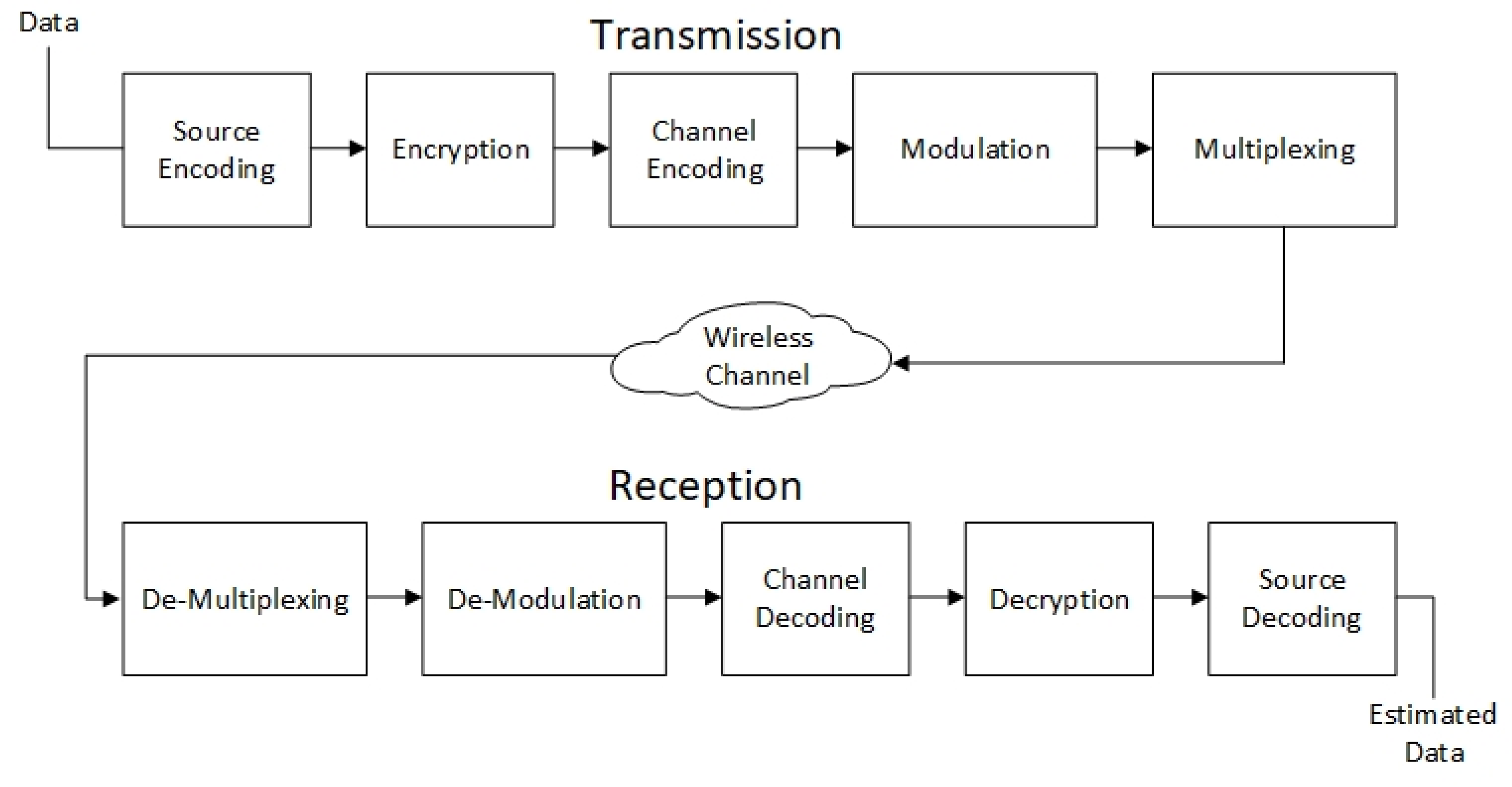
2. Wireless Communication and Protocols’ Characteristics

The term wireless communication was first introduced in the 19th century, while wireless communication technology was developed in the following years. This medium allows for transmitting information from one device to another. With the use of this technology, data can be sent by air without the use of cables, but also any wires, including electronic ones, replacing them with electromagnetic waves such as IR, RF, satellite-based, etc. [1].
Figure 1 shows the basics of wireless communication functioning diagram. During transmission, the encoder converts the signal to a suitable form so that it can be sent through one of the available protocols. Data encryption protects the signal. Channel encoding is designed to reduce interferences. Then, this signal is multiplexed with other signals. The situation is analogous on the receiving side, including demultiplexing, demodulation, channel decoding, decoding, and source decoding. This makes the task of the receiver opposite to that of the transmitter [1].
Nowadays, various types of devices use the wireless communication system, which allows the users to communicate even from areas located far away from each other. There are many devices which use wireless communication, to name but a few, mobile phones, wireless phones, Zigbee wireless technology, GPS, Wi-Fi, satellite TV and wireless computer parts. Today’s wireless phones include 3/4/5G networks, Bluetooth and Wi-Fi technology [2].
According to [3], scientists and programming crews, including the IEEE, make every effort to implement wireless connectivity without changing existing computer equipment. As a result, there is a strong emphasis on using existing computer hardware and software to convert data into a new hardware-compatible format added to the computer using existing ports or PCMCIA connections. This means that the wireless communication will be transparent to the user.
The advantages of wireless communication include the possibilities of high-speed data transfer, low cost of maintenance, and installation of these networks. Internet access can be obtained from any place wirelessly. Moreover, wireless technology offers many benefits for computers and their users, including faster response times, shorter time spent on formalities, longer online time for users, just-in-time and real-time control, and closer communication between clients and hosts. According to [3], the problems to be solved in wireless communication are:
  • Data integrity—transmission with relatively no errors,
  • Speed—as close as possible to the speed of current wired networks,
  • Protection—ensuring that data in the air is encoded and cannot be overheard by unwanted receivers,
  • Compatibility—ensuring that many of the protocols that will certainly be created are compatible with the standard to enable interoperability,
  • Environmental safety—electromagnetic radiation forces must be kept at normal levels.
It cannot be denied that wireless communication has a number of advantages but also several disadvantages. The examples of the most common drawbacks are its safety, interference, and health effects. In the case of wireless communication systems, it is open space that is used as a medium to transmit signals. As a consequence, it is very likely that radio signals from one wireless communication system or network can interfere with other signals. A good case in point is Bluetooth or Wi-Fi (WLAN), both of which use 2.4 GHz for communication. When both are active simultaneously, there is a risk of interference. Another major threat to wireless communication is the difficulty of ensuring a high-security level for data transmission. Wireless signals that spread through the air can be easily intercepted by an unauthorized person. That is why it is critical to secure the wireless network so that unauthorized users are not able to misuse the information. Because signals are transmitted in the open air, signals and confidential information can be intercepted and copied by an intruder. There are also health aspects. Being continuously exposed to any type of radiation can be possibly dangerous. Although RF energy levels that can cause damage are not accurately determined, it is recommended that RF radiation be avoided to the maximum [3].

2.1. Wireless Communication Protocols Overview

The challenge for wireless networks is the Internet of Things/Everything (also known as IoT/IoE). Since IoT is a very diverse field, there is certainly no universal communication solution. The most common types of wireless are the following standards [4]:
  • Low Power Broadband Networks (LPWAN) provide long-distance communication on small, cheap batteries that are long-life. This technology has been specifically designed to support large-scale IoT networks spanning extensive campuses, both the industrial and commercial ones. LPWANs can combine all types of IoT sensors—making it easy to combine many types of applications such as facility management, building control, remote monitoring, smart measuring, and employee safety, to name but a few. However, due to the fact that LPWANs can only send small blocks of data at low speed, this makes them better suited for applications which are not time-sensitive and do not require high throughput.
  • Mobile networks (3G, 4G, 5G) offering reliable broadband communications for various voice calls and video streaming applications. Unfortunately, their disadvantages are very high operating costs and power requirements.
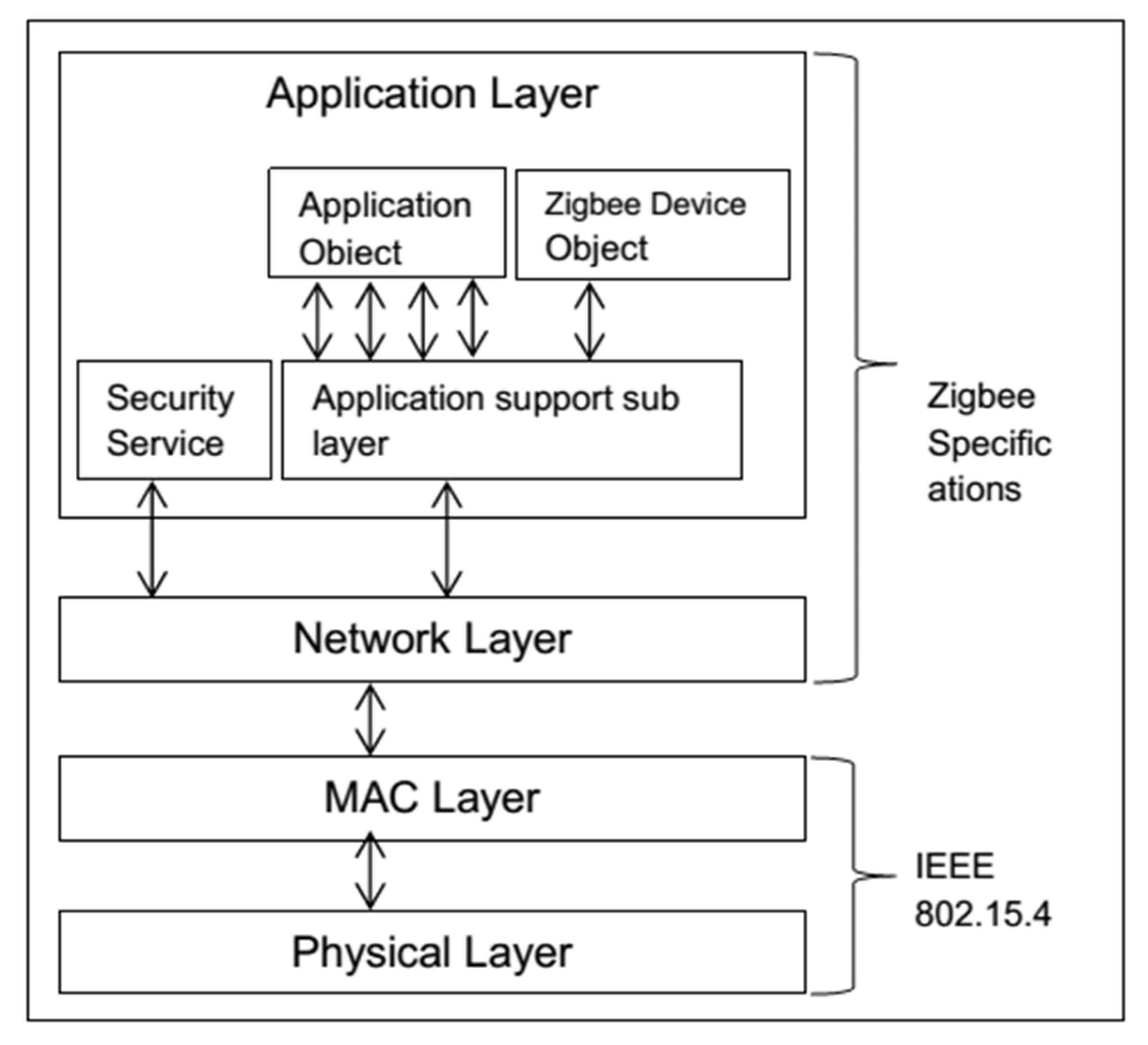
  • Zigbee and other “mesh” protocols are short-range, with a low power wireless standard (IEEE 802.15.4). It is widely used in grating topology to extend the range through passing sensor data through a number of sensor nodes. In comparison to LPWAN, Zigbee allows a higher data transfer rate, but simultaneously a significantly lower energy efficiency because of the grating configuration.
  • Bluetooth (IEEE 802.15.1 v1-5) is a very popular short-range communication technology in today’s consumer market. Bluetooth Classic was initially designed to exchange point-to-point or point-to-multipoint data (up to seven sub-nodes) between consumer devices. In order to optimize the power consumption, in small consumer IoT applications, Bluetooth Low-Energy was later introduced.
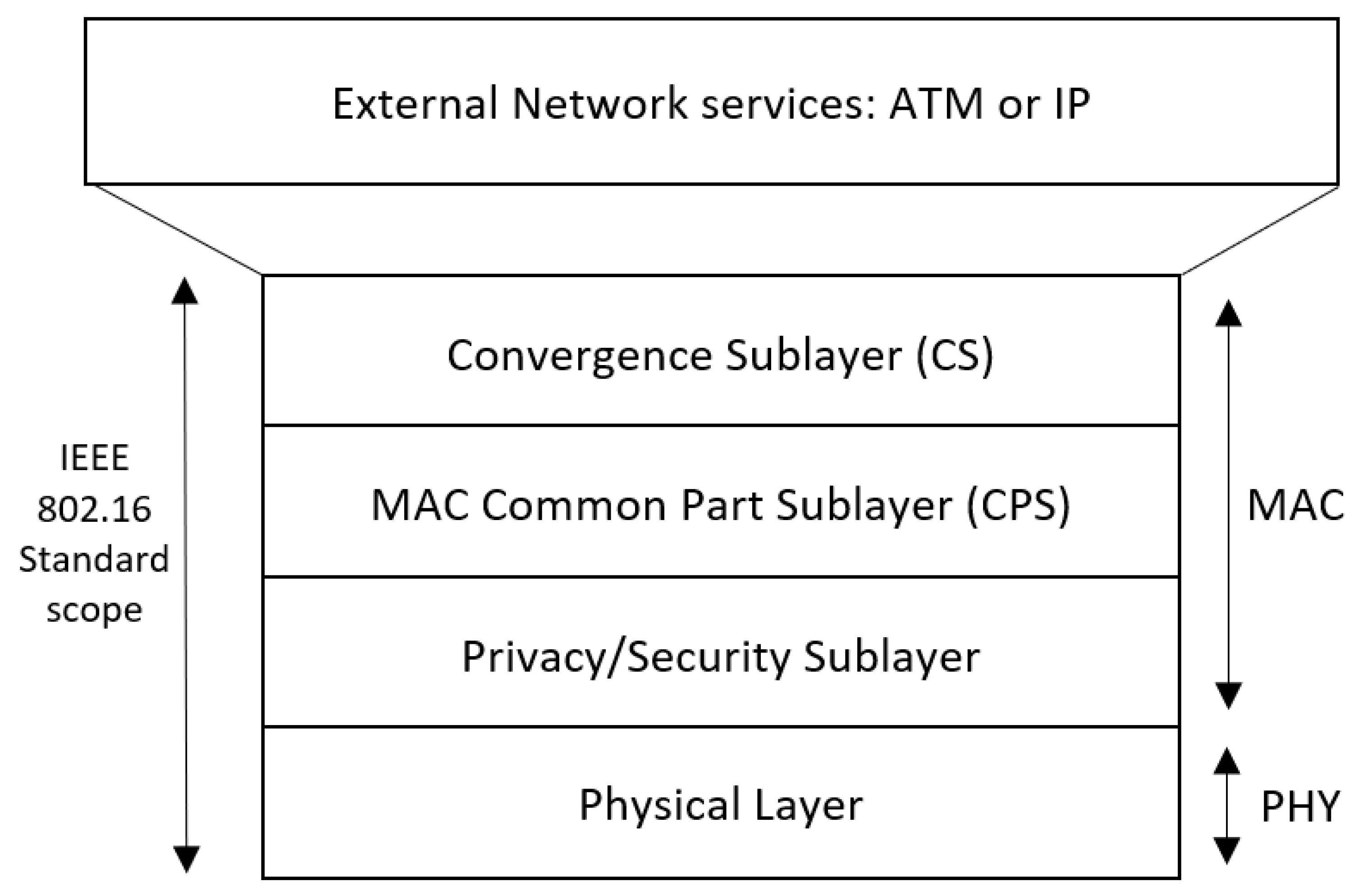
  • Wi-Fi (IEEE 802.11a/b/g/n/ac/ax, WiMAX—IEEE 802.16) provides high data transfer rates not only in corporate but also home environments. However, when it comes to the IoT space, its coverage, scalability, and power consumption are limited, and this makes the technology much less common. Due to high energy requirements, Wi-Fi is not always a viable option for large battery IoT sensor networks, especially in industrial IoT and smart building scenarios. Instead, it is used to connect devices that are easy to connect to an electrical outlet, such as smart home gadgets and devices, digital signage, or security cameras.
  • Radio Frequency Identification (RFID, ISO/IEC24791) uses radio waves to transmit small amounts of data from an RFID tag to a reader at very short distances. So far, technology has significantly revolutionized retail and logistics sectors. The attachment of an RFID tag to a variety of products and devices allows companies to track their inventory and resources in real time—this, in turn, enables better inventory, production planning, but also optimizing supply chain management.
At present, in many critical applications, one of the most used technologies are standards: IEEE 802.1, IEEE 802.15.4, and IEEE 802.16 [4].
The IEEE 802.11 standard offered the first possibility of connecting computers via a wireless network. From it, the whole family of standards began to develop, which is commonly called Wi-Fi. In the first version, “b”, the maximum throughput was not too high. It reached an average speed of 1–5 Mbps, operating at 2.4 GHz. The “b” standard was not very efficient, so an attempt was made to increase speed by changing to the 5 GHz band, increasing the throughput to 54 Mbps. Currently, the 802.11b standard is no longer used for a long time, while 802.11a is rarely used. Another version introduced was the “g” standard operating in the 2.4 GHz band and offering backward compatibility with 802.11b, with a maximum throughput of 54 Mbps. The next version was 802.11n, with a maximum speed of 600 Mbps using two bands—2.4 and 5 GHz. 802.11n began to use MIMO technology using multiple antennas to transmit and receive, improving coverage and performance. With MIMO, the radio signal is split into several streams, which are independently transmitted and received by several receivers simultaneously [5].
Figure 2 presents the architecture of the Zigbee protocol, also known as IEEE 802.15.4. This standard is aimed at defining the MAC layer and physical layer for Low-Rate Wireless Private Area Networks (LR-WPAN). As this standard is intended for low power consumption, a low data rate, and a low-cost wireless network, it is most often used in sensor networks. Compared to Wi-Fi, this network uses less power, but at the expense of speed. The most commonly associated with this standard is the ZigBee protocol. This standard also includes ISA100.11a, WirelessHART, MiWi, 6LoWPAN, Thread, and SNAP. In contrast to the 802.11 standards working in the 2.4/5 GHz band, 802.15.4 operates on several different bands depending on the region, e.g., Europe works on various bands different to North America [6].
WiMAX (which stands for Worldwide Interoperability for Microwave Access) is a wireless data transmission technology based on IEEE 802.16 standard to provide broadband wireless access (see Figure 3 for architecture details). Initially, the technology was subject to several restrictions, mainly related to the frequency band used (initially the 10–66 GHz band) and line of sight (LOS) requirements. The proposed IEEE 802.16d amendment eliminated this problem by reducing the frequency to a maximum of 11 GHz. Additionally, HARQ (Hybrid Automatic Repeat Request) transmission control mechanisms and Quality of Service (QoS) implementation were introduced to reduce transmission delay and introduce process priorities. The latest approved version is the 802.16e standard introducing mobility of devices in the 2–6 GHz band. The mobility of devices has been achieved by implementing mechanisms for the handover of connections from one base station to another while the connection is active. This method is known from the mobile network, providing transparency of switching the whole state of the transmission session to another base station, which ensures better quality of transmitted signal [7].
It is expected that the 5G communication will reach the market by 2021. Subsequently, it is expected that 6G communication will be launched between 2027 and 2030. It is challenging to achieve the 5G/6G targets and the Internet of Things based on the touch Internet. There are a number of critical and challenging issues and these include: low latency, low power consumption, high bandwidth, high security, massive connectivity, high QoE, and reliable connectivity for 5G communication systems. The RF systems are the only ones not able to satisfy the increased demands of future 5G/6G and IoT networks. Optical wireless communication (OWC) technologies are the best complementary RF network solution. It is the coexistence of RF and optical wireless systems that can achieve the objectives of the above-mentioned networks [8].
Table 1 presents the comparison of selected parameters of different wireless standards.

2.2. Wireless Communication Security Aspects

It is not possible to communicate successfully only with a wireless (or wired) connection. It is necessary to use the protocols used to agree on the type and form of data transmission, sender, recipient, control bits, etc. Multiple protocols are available for the communication layer, the most important of which are TCP and UDP. The Internet mostly uses the TCP protocol, which is reliable and has a built-in check that the message has arrived. UDP does not have this, but it is much faster and is mainly used for telephony and video. The message layer works on the communication layer. It can be HTTP, HTTPS, REST, or MQTT (above TCP) or CoAP (above UDP). REST works above HTTP and HTTPS for network devices, and IoTivity is a protocol above UDP that recognizes connected devices. Most protocols also regulate comprehensive message encryption (REST only guarantees encryption when running on HTTPS). With IoT, devices with (embedded) controllers can be connected, enabling these devices to use specific services on the Internet [21,22,23].
There are five methods of security in the current Wi-Fi networks available to users. Below are the security measures from strongest to weakest:
WPA2 + AES;
WPA + AES;
WPA + TKIP;
WEP;
Open Network (without security).
Wi-Fi networks use the 4-way handshake process to establish the connection. The 4-way handshake is defined as a process of exchanging four messages between an access point (also know as authenticator) and the client device (also known as supplicant) in order to generate some encryption keys which can be used to encrypt actual data [24]. One of the most widespread threats in wireless technologies is a DoS (Denial of Service) attack that disrupts users’ access to a network. This goal is usually achieved by overloading a given resource with a considerable amount of traffic or sending many malicious queries. Protection against it is almost impossible, but it is possible to find an intruder based on his signal [25]. Table 2 shows basic comparisions between three Wi-Fi networks security standards.

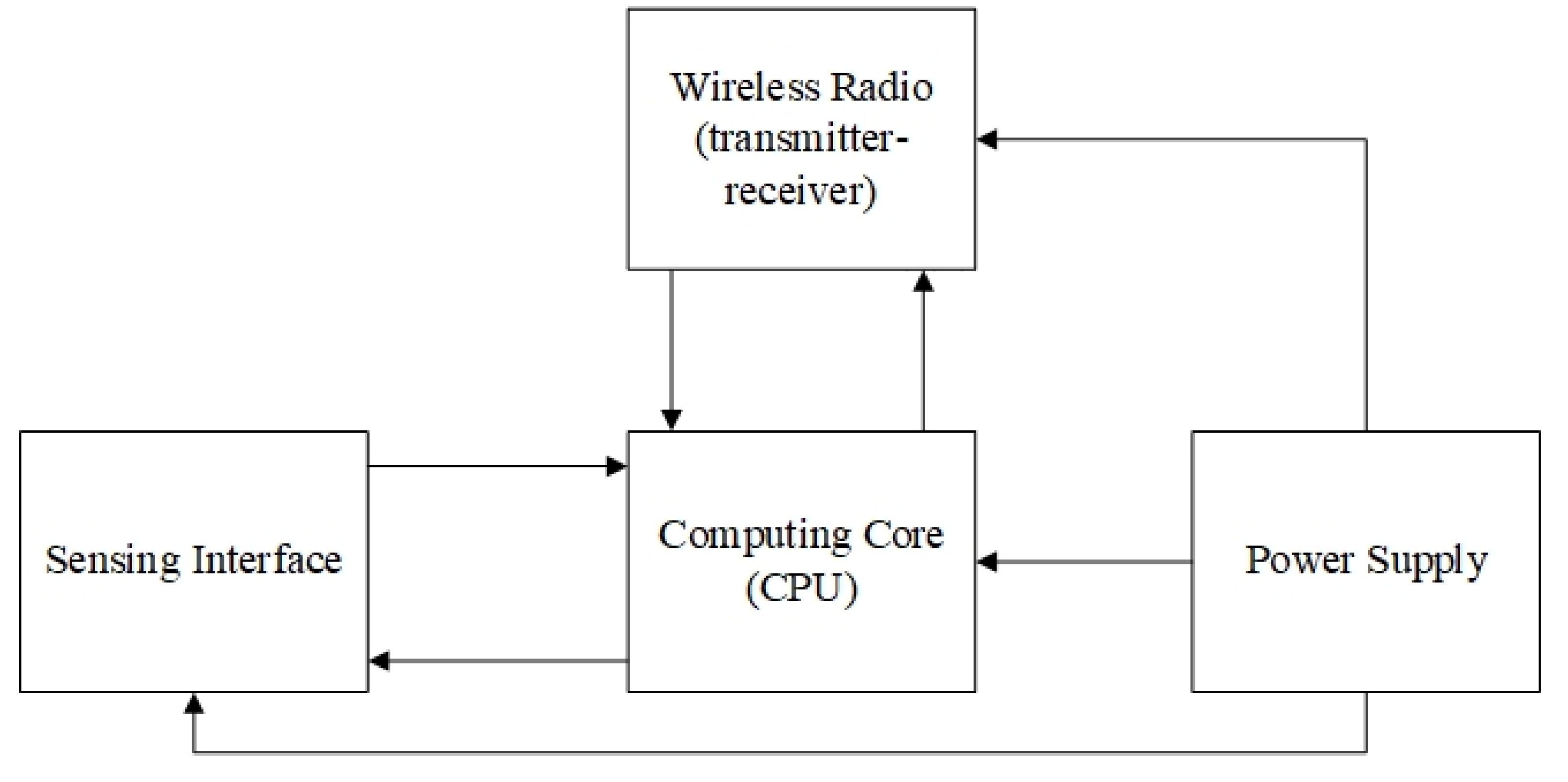
3. Base of the SHM System

Currently, wireless sensors are becoming very popular. They should not be treated as a kind of sensor but as a network of sensors. Structural Condition Monitoring (SHM) is based on using sensors for non-destructive testing (NDT). Thanks to the integration with commercial and military aircraft structures, it is possible to periodically or continuously monitor the initiation and growth of damage without decommissioning, disassemblying, and manual inspections, which are costly and time-consuming [26]. On the one hand, the lack of cables and connection ports significantly reduces the structural weight, but it simultaneously requires a separate power source, weighing more. Furthermore, adding batteries to the SHM system may result in extra maintenance problems.
There are many concepts and designs for SHM systems, with different costs and durability, e.g., Comparative Vacuum Monitoring (CVM) developed by Structural Monitoring Systems (SMS, Nedlands, Australia; Century City, CA, USA and Ashford, UK) and an Acousto-Ultrasonics (AU) technology called SMART Layer developed by Acellent Technologies (Sunnyvale, CA, USA) [26].
In general, SHM technologies can be divided into two categories: local techniques when the observed area is limited to the area underneath the sensor (this is the case, for example, with CVM and electro-mechanical impedance (EMI) techniques) and global techniques when damage can be detected at any point in the structure by a network of appropriately distributed sensors [27].
Real-time health monitoring is the basic principle, and it is the fundamental parameter of cost–benefit analysis investigations. In the case of, e.g., aircraft, it is continuous health monitoring using airborne wireless sensors and damage assessment employing a central station. In many studies [28], it has been stated that it is not practical to use wireless sensors to monitor an aircraft’s whole structure because of the decrease in weight and reliability of batteries. When performing SHM basins on the ground after each flight, this operation may still prove to be impractical, as the exact detection range of the sensors requires a large number of sensors to monitor the entire aircraft. Due to data processing operators being required to run each sensor one by one, gather all the data and process the data to determine the extent of damage and its location. The total detection procedure can take up to three to four days. Given that each flight’s maintenance time takes only 30 min, it is not practical to perform checks after each flight [28,29].
Nowadays, wireless sensor nodes can be built in a small size and weight-optimized way. However, continuous monitoring and subsequent processing of all data collected by the sensors take a considerable amount of time. The raw data that are accumulated in the SHM sensors must be filtered in order to remove noise, and an intelligent diagnostic algorithm must be applied to convert the raw data into useful damage information. Subsequently, predictive algorithms are used to forecast future damage increases. Given that thousands of sensors are needed to monitor the entire aircraft processing, all the data take a long time. Thus, the cost of signal processing and computation may exceed the cost and benefit resulting from the use of SHM [28,29].
Therefore, this issue is fundamental, and the analysis of the cost/efficiency ratio of the entire SHM system and its individual processes is even crucial.

4. WSN Systems in Different Applications: Aerospace, Bridge Structures, and Wind Turbines

SHM is currently the basis for many extensive structures and products. These systems are based on NDT sensors integrated into structures including aircraft, bridges and wind turbines, to name but a few. Furthermore, they allow periodic or continuous monitoring of the creation and growth of damage without the cost and time necessary for decommissioning disassembly and manual inspections.
The widespread use of wireless technology and wireless sensor nodes, in fact, makes it possible to consider the sensors not individually but as a network of sensors or as a whole platform. The main motivations for using these technologies include removing heavy cables and connection ports by substituting them for a wireless connection. The lack of cable and connection ports can, on the one hand, significantly lower the structure’s weight, but on the other hand, it requires a separate power source at the same time, further reducing weight. Furthermore, adding batteries to the SHM system might require extra maintenance issues. Therefore, it has been proposed by some researchers to collect energy for sensors by capturing the required electricity from solar energy or structural vibrations. Though it may seem to be a promising research area, adding this world-class technology to SHM systems without significantly increasing weight remains a challenge. For this reason, technological maturity is still rather limited and requires further research and test implementations [28,29].
A sensor node usually consists of three to four main elements (Figure 4): measuring part of sensor data, computing core (CPU), wireless transmitter–receiver and power supply (battery). The central part of the wireless sensor node is the microprocessor which is responsible for processing all data received from the memory, sensors and receive/transmit signals. The transmitter/receiver communicates with an access point or other sensors using a radio frequency medium. The transmitter can retrieve data from the microprocessor in order to transmit it further by radio and vice versa. The battery is designed to power all parts of the node long enough to ensure energy continuity in all parts throughout the flight. The last part is the sensors that send analog data to the microprocessor [30].
Although traditional batteries still power most sensors, research is being carried out into battery-free sensors’ production using passive radio frequency identification (RFID) systems [30].

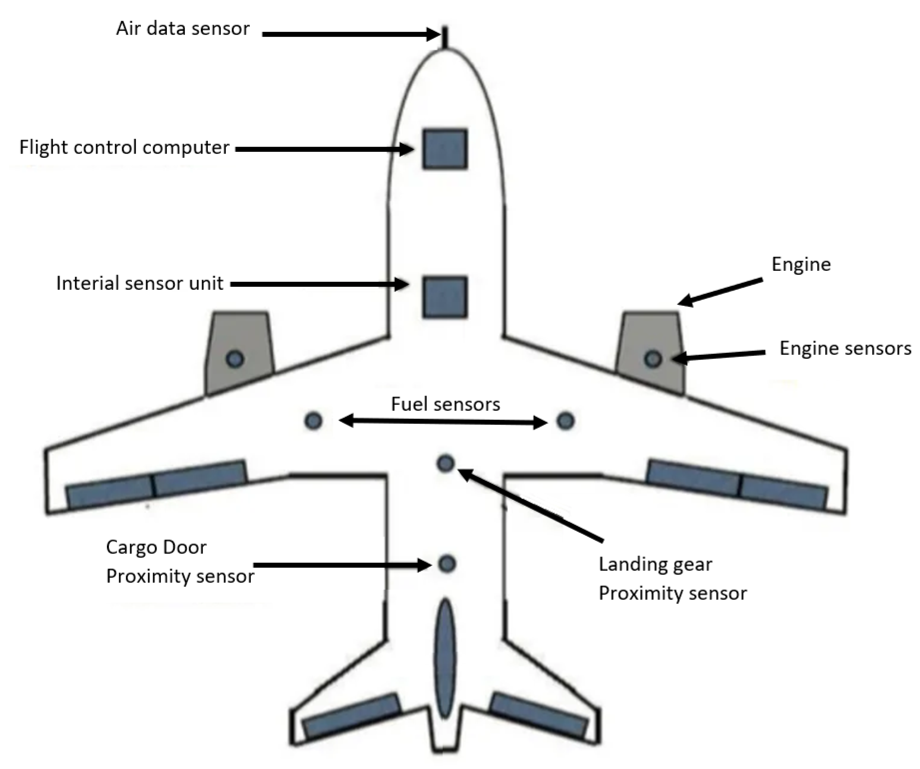
4.1. WSN in Aerospace

The improvement of efficiency and flexibility while reducing weight, fuel consumption, and maintenance costs in aircraft can be obtained by the ‘Fly-By-Wireless’ paradigm based on wireless communication. The complexity of avionics communication architecture increases with the increasing number of interconnected subsystems and the growing number of data exchanges. In order to follow this trend, the current aircraft architecture of the next generation, including the A380, A400M or A350, comprises a high-speed backbone network based on AFDX (Avionics Full Duplex Switched Ethernet) to connect critical subsystems. Subsequently, it is possible to connect each specific avionics subsystem directly to an associated sensor/actuator network that is based on a low-speed data bus such as ARINC429 and CAN. Despite the fact that this architecture meets the major requirements, it also brings integration costs resulting from a large number of wires and connectors. To give an example, it is estimated that the costs associated with cabling during manufacture and installation are $2000 per kilogram, which accounts for $14 million for an aircraft such as the A320 and $50 million for a B787 in terms of the total cost. In particular, there is approximately 500 km of cables used in the new generation A380 aircraft. Apart from the costs, avionics connections are still subject to structural failures and fire hazards, which significantly reduces not only their reliability but also their maintenance costs. In order to solve these emerging problems, the implementation of avionics without cables will not only significantly improve aircraft performance and reliability, but it will also lower integration, fuel consumption, as well as maintenance costs [31].
In aviation, many different standards can be used for wireless communication between sensors, both open and commercial. According to [31], networks which are based on the IEEE 802.11 standard are not designed for in-flight transmission, but the IEEE 802.15.4 standards are much better. The authors emphasize that the new WAIC standard technology designed only for the aviation industry will significantly increase communication over short distances, improving communication between sensors and aircraft systems.
For a wireless network in airplanes, good bandwidth is required to send and collect large amounts of data collected by the sensors. Looking at the capacity of various wireless technologies described in Table 1, most of the protocols based on the 802.15.4 standard operate at speeds up to 250 Kbps with low power consumption. If you consider receiving a packet and processing it by a microcontroller, this speed can drop by up to half. It is also necessary to take into account the assumptions of sensor networks. Usually, they do not have the possibility of direct connection to the base station, which can further reduce the transmission speed, thus weakening the whole network’s reliability [31].

4.1.1. Wireless Signal Propagation

However, its non-deterministic behavior and its sensitivity to interference and jamming can solve many problems. However, these features may not be sufficient to provide the real hard telecommunication required by aircraft applications.
Research in [32] has indicated the use of an access point with 802.11a technology in the aircraft. Omnidirectional antennas should be used. Thanks to that, the access point can evenly send waves in cabin space with equal probability. This ensures that no area in the cabin will contain more waves than another. It is worth emphasizing that, the higher power coming out of the access point, the more interference can be caused by aircraft electronics. Therefore, it is essential to select such power and the number of access points to eliminate this problem [32].
The authors in [32] state that the four access points with 802.11a technology cover almost all planes. These four access points must have reasonable transmit power levels that ensure minimal interferences with plane electronics.

4.1.2. AWSN Networks Structure

The desired parameters are acquired and communicated by various sensors. Due to the fact that current sensors are hardwired, and the fact that the number of sensors is growing due to automation, the accuracy of intended aircraft functions is increased (Figure 5).
The sensors are distributed throughout the aircraft and are connected by wired networks for signal processing and communication. Line-replaceable units (LRUs), which integrate various sensors, also use a wired approach for communication. Signal integrity and fault detection methods are the key features of signal processing in aviation applications. The application of wireless sensors in aircraft results in enormous benefits in the aircraft’s design optimization, flexibility in sensor configuration, as well as its weight optimization. What remains to be solved is the proper placement of wireless sensors and networks in the plane in accordance with protocols, standards, and certification.
According to [31], the network should be divided into four main areas. The first and most important part is a set of sensors (e.g., pressure, temperature, vibration, etc.) and access points that are part of the so-called internal AWSN network. The second part of the network is all network switches that connect wireless and wired devices, i.e., aircraft computers or internal systems. The third part of the AWSN network includes all portable devices (sensors are not included here), onboard computers, and other network equipment. The last part of the network is the Internet connection, e.g., by means of ATG (Air To Ground) and satellite connections.

4.1.3. Selected Wireless Communication Protocols Used in Aviation

The Avionics data and communication network (also known as ADCN) is mainly comprised of three types of systems (Time Critical: Avionics network; High Performance: Aircraft and Cabin Operations; Open World: in-Flight Entertainment). The highest level of criticality is critical, whereas high performance and open-world correspond to medium and lowest levels. In the case of open-world and high-performance systems, increasing bandwidth utilization is one of the main constraints, while predictable behavior and timing guarantees are not necessarily a fundamental design issue. Within the field of open-world systems, in [34], the authors referred to the conducted simulations and experiments with the use of standard wireless technologies for an In-Flight Entertainment Network (IFE). The results obtained for heterogeneous architecture based on Ethernet and Wireless USB technologies are promising in QoS. For high-performance systems, authors in [34] referred to tested Ultra WideBand technology for in-cabin communication with optimized resource allocation, and average communication latency was achieved with the use of simulation.
The following standards apply in data and communication networks (ADCN):
  • AFDX® (IEEE 802.11e) makes use of a unique protocol in order to provide deterministic time management and redundancy, ensuring secure and reliable communication of critical and non-critical data. AFDX® communication protocols have been developed from commercial standards (Ethernet MAC addressing IEEE802.3, IP Internet Protocol, UDP user datagram) in order to obtain the required deterministic behavior for avionics applications. Virtual Linked Terminal Systems (or LRUs) communicate with traffic shaping through bandwidth allocation gaps (BAG). AFDX® data transmissions are used on the following aircraft: Airbus A380/A350/A400M, Boeing B787 Dreamliner (ARINC 664), ARJ21, and Super jet 100. AFDX®/ARINC 664P7 is used as the core for all systems, such as flight control systems, cockpit avionics, air conditioning, power equipment, fuel systems, landing gear, and more [35].
  • The CAN bus is a 1 Mbps data bus that works in accordance with an event-triggered paradigm where messages are transmitted with the use of a priority-based access mechanism. CAN bus operates by using a producer/consumer communication scheme which is based on a unique identifier per message type. The CAN messages are broadcast on the bus; then, each CAN equipment will filter the consumed data based on the CAN identifier. The collisions on the bus are solved following a CSMA/CR protocol (Carrier Sense Multiple Access/Collision Resolution) by the bit arbitration method. The CAN frame comprises a payload of up to 8 bytes and an overhead of 6 bytes because of the different headers and bit stuffing mechanism [36].
  • The ARINC 429 and MILSTD 1553B are communication standards used in both military and commercial aviation. The ARINC 429 connects LRUs onboard Boeing 737 and other civil aircraft with the use of distributed avionics architectures. The MIL-STD 1553B is applied in most military aircraft for critical flight control and various mission systems. Both of them are half-duplex communication standards. The ARINC 429 connects the LRU. The MIL-STD 1553B connects multiple devices via a common bus via a point-to-point wiring scheme. They are now used in manufacturing and space aircraft; however, certain shortcomings in modern aircraft performance have resulted in the adoption of extended and modified versions of these standards [37].
  • ARINC 653 is a specification for an application executive used for integrating avionics systems on modern aircraft. This specification is aimed at enforcing fault containment, and preventing fault propagation from one partition to another, which eases the application’s life cycle verification, validation, as well as certification procedures. The main areas of use of the ARINC 653 specification are integrating different systems into a single environment (CPU environment), integrating different OS systems, standardization of safety-critical control systems and time and space partitioned systems [38].
  • The IEEE 1451 standard describes the common functions, communication protocols, as well as transducer electronic data sheet formats. The purpose of the standard was to standardize plug and play technology, making it easy to connect a transmitter from any manufacturer to any control and measurement network so as to make the transmitter independent of the protocol used in a given network. This standard’s key element is to define the TEDS (Transducer electronic data sheet) format that stores relay identification, correction data, calibration, as well as manufacturer information [39].
  • The WAIC system (Wireless Avionics Intra-Communication) is also based on the IEEE 802.15.4 standard. Studies indicate that the best band for WAIC is 4.2–4.4 GHz, as it shares a similar band with a radio altimeter. Moreover, too strong electromagnetic waves from wireless devices inside an aircraft are exposed to high attenuation. As they penetrate various metal and composite objects, it is essential to choose the right frequency not to interfere with other components. WAIC is designed to integrate multiple devices in a single aircraft fully. The system itself is adapted to low range (<100 m) and low power consumption (10 mW for small transmitters and 50 mW for large transmitters). It should be emphasized that the standard does not provide a connection to the Internet. It only serves as an intermediary for, among others, data transmission methods, i.e., satellite network [31].
  • 7 ECMA-368 (High Rate Ultra Wideband PHY and M.A.C. Standard) is a standard for high-data-rate networks within the airplane. There are solutions for optimal node placement, quality of service mechanisms, and loss-free mobility support. Ultra-wideband technology provides better indoor performance compared to traditional narrowband systems. The wide bandwidth allows resistance to channel effect in dense environments and allows very accurate satisfactory time-space resolutions for very precise positioning inside UWB nodes. The standard sets a low spectral density below ambient noise for a low probability of signal detection and consequently increases communication safety. The standard provides high periscosity data transmission over short distances (up to 100 Mbps at <10 m) [40].

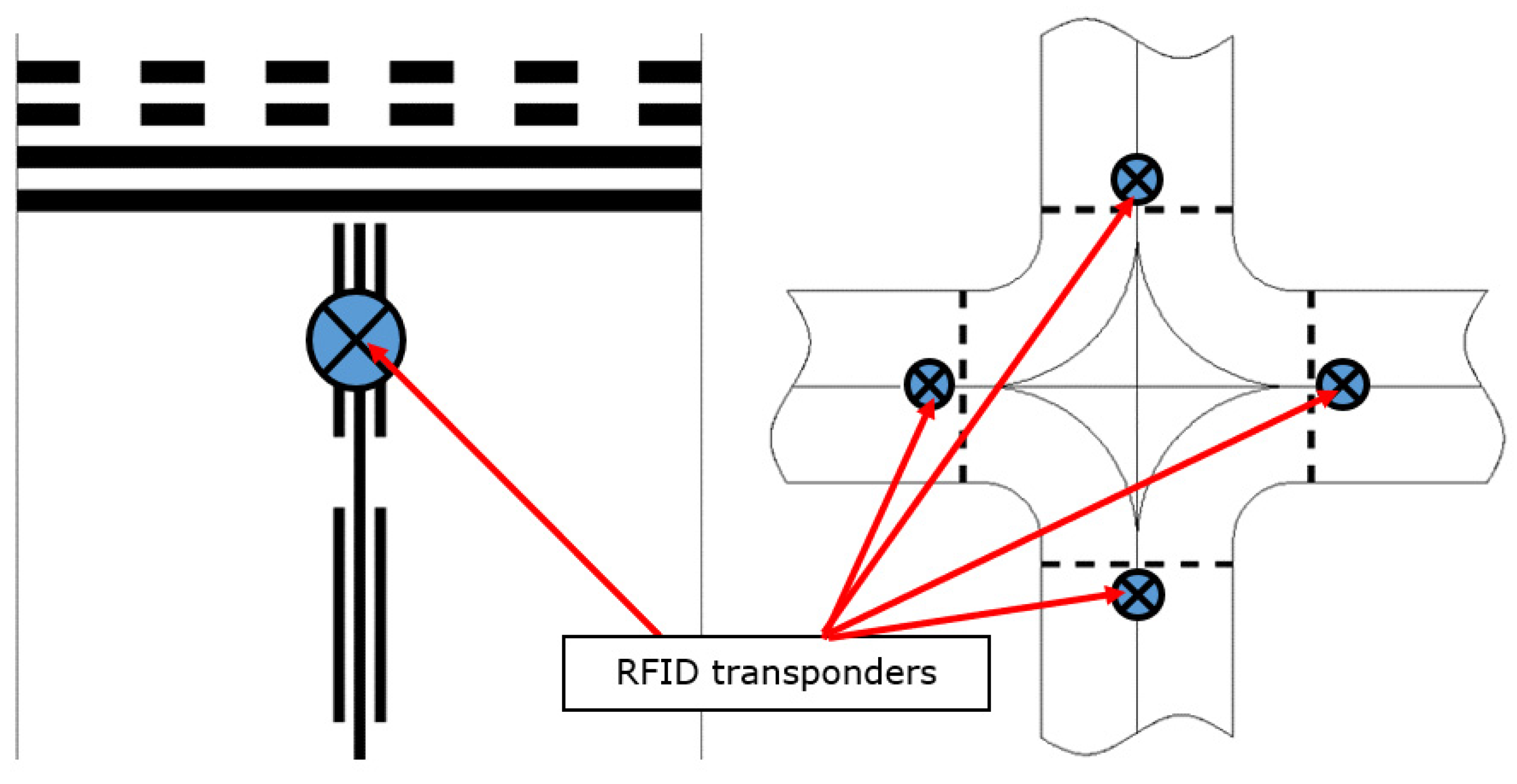
4.1.4. Transmission Information System for Taxiing on the Aprons and Taxiways Using RFID Technology

Along with the progressing automation of aircraft control processes, the reliability and quality expectations of these processes are increasing, not only in the air but also on the airport apron. And taxiways. Each valid flight begins and ends at the airport apron, which must be navigated properly and efficiently in order to maintain a high level of airport safety and airport capacity [41].
There are two basic types of taxiways: normal taxiways and expressways. Their parameters are standardized and depend, among other things, on the air traffic and its intensity, which makes it easier to quickly release the runway to serve other aircraft [42].
For navigation on the airport apron, pilots use horizontal and vertical signs, as well as automatic control systems, which are based on more and more perfect vision systems. Global positioning systems such as GPS, GALILEO and, among others, radars, which co-create anti-collision systems, are also used for airport navigation [43,44,45,46].
In order to increase security, the diversification of information sources is used. For this purpose, an additional RFID-based navigation system may be applied [47,48].
This technology is widely known and used, also in aviation, among others, for monitoring and tracking components and analyzing their wear [43].
This system enables the transfer of information in an object or group of objects. It is based on cooperating transponders (passive or active) and a reader, stimulating them to operate and read the information sent [49].
In airport navigation, RFID technology can be used to wirelessly transmit the following data to an aircraft [47,50,51]:
information (e.g., about the position on the taxiway, about other airplanes nearby) or
commands (stop, continue taxiing).
Transponders can be installed directly on the surface (Figure 6) or combined with taxi lamps. In the second case, they can be active transponders that use lamp power [47].
A beneficial effect of using this type of solution is [47]:
Possibility of transmitting additional information to the automatic taxi control system, such as: the position on the taxiway, about an upcoming intersection, about other nearby objects, and commands for the automated taxi system.
It provides additional information to increase the crew’s situational awareness, such as: warnings about approaching a taxiway/runway intersection and information about geographic location.
Possibility of replacing other, completely passive systems, based on graphic signs—so that the information transmitted to the aircraft may change, be programmed remotely, due to the current traffic situation, weather, and others;
Easy for configuration infrastructure;
Flexible system structure.
This solution has also some weaknesses:
The range between devices is limited to a maximum single tens meters
Different frequencies engaged depending on the region of the World, so multi frequency devices are required to increase flexibility and portability of RFID based systems,
Sensitivity to short contact time. The communication could not be established if visible time was too short because of capacitors’ performances and limitations.
The above-mentioned solution has been tested under laboratory conditions. During the tests, the control system responded to the transmitted information and steered the model as intended. The operational range of transponders and readers was also checked in airport conditions by testing the possibility of transmitting information to the aircraft. The obtained results suggest the option of using this type of solution in both manned and unmanned aviation.

4.1.5. Further limitations for Wireless SMH within Aerospace

In addition to the signal propagation problems experienced when operating within an aerospace environment, the implementation of SHM has further hurdles that must be surpassed in order to be efficiently implemented. The power of the restrictions mentioned above of wireless sensors is of particular concern for aerospace. The use of solar panels, commonly found in civil infrastructure monitoring devices [52], is not feasible. Furthermore, the use of batteries is often limited as, in addition to safety concerns, temperature fluctuation in flight is large, which significantly affects their performance. Degradation of batteries over time with continual charging also requires regular replacement to be carried out. A proposed alternative to batteries’ use is instead using capacitors, which, although having a lower energy density, do not degrade over time or suffer from temperature fluctuations [53]. Super and ultra-capacitors with higher performance through narrower dielectrics further increase their feasibility.
Whether batteries or capacitors are utilized, for a wireless node to achieve long term use without manual charging, some form of energy harvesting is essential. Vibration harvesting is an area of great interest due to the abundance of energy available in flight. This is harvested in three ways, though either piezoelectric, electromagnetic, and electrostatic methods [54]. Piezoelectric devices are often favorable due to their simplicity and ability to be applied as a Micro-Electro-Mechanical System (MEMS) device [55]. Although recent advances have significantly increased vibration harvesters’ energy output, their output is realistically limited to under 1 mW. The actual outcome depends on operating conditions and size. Additionally, although researchers have attempted to broaden their resonance [56,57], which harvesters have at some meaning, making appropriate selection of a device for a given application is essential.
Although it has been less researched, the generation of electrical energy from thermal gradients seems to be another promising energy harvesting approach; on an aircraft’s outside skin, a large temperature change (upwards of 50 °C [58]) takes place during take-off and landing. Through the phenomenon known as the Seeback effect, Thermoelectric Generators (TEG) convert this change into electricity. Although less efficient than heat pumps, TEG is maintenance-free, contains no chemical reactions or moving parts, and has a long life span [59]. Researchers have successfully applied TEG in a lab setting, generating 126 J over a simulated 80-min flight cycle [60]. A different, smaller device was also substantially flight tested, where an average of around 20 J was generated per flight cycle from the fuselage skin [60].
Although developments are being continually made in energy harvesting, it is clear that there is a limit to the available power. This can make operations that would be simple in some situations very complex onboard an aircraft. Data communication is of primary concern. It is typically the highest energy drain for a wireless node [61]. Minimizing the transfer of recorded data is one aspect of reducing this expense. However, other essential operations must often be considered. Time synchronization of nodes, for instance, is vital for specific SHM applications, such as vibration or Acoustic Emission (AE) monitoring. Required accuracy is heavily dependent on the technology in use. Vibration-based monitoring must be within 50 μs [62], whereas, for AE, microsecond accuracy is required for some location approaches to be accurate. Although time synchronization of this accuracy is possible, the power necessary to do so may make it unviable for self-powered applications, making alternative approaches where lower accuracy is required advantageous.

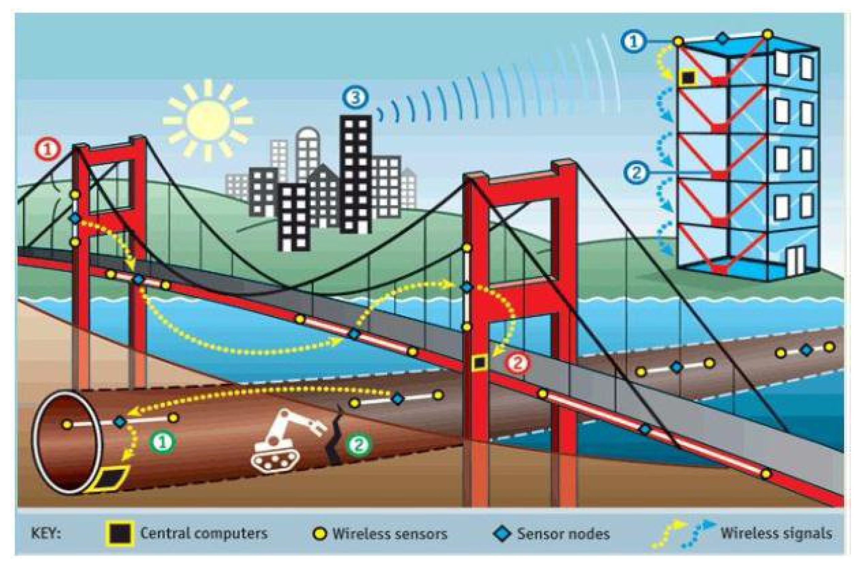
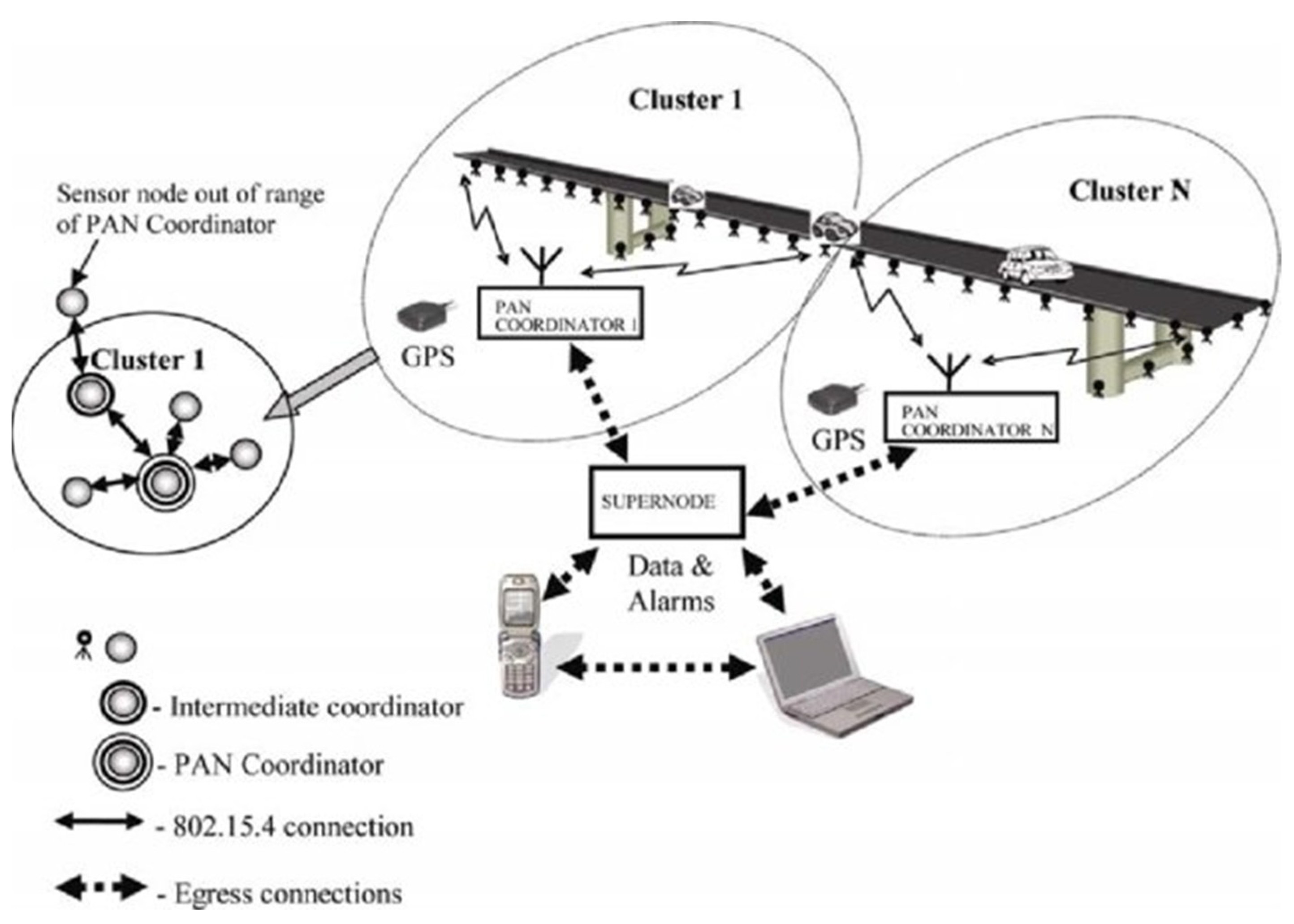
4.2. WSN in Bridge Structures

Modern societies’ everyday existence and development are significantly dependent on civil engineering structural objects like bridges, towers, power generation systems, and off-shore platforms. Bridges and viaducts, as structures ensuring the continuity of road infrastructure, ensuring crossing over natural and artificial obstacles, are the key elements of the functioning of modern societies and their economies. Therefore, their safe use is crucial from an economic point of view. Therefore, dedicated SHM systems have been developed for decades. From a whole range of different types of engineering structures, the transportation infrastructure objects are expensive to build and maintain. The consequences of their sudden failure are hazardous and have serious consequences. The examples of civil engineering structures (for instance, bridges, tower buildings, and tunnels) equipped with SHM systems using wireless sensor networks are shown in Figure 7 [52].
A special category of structures for which SHM systems have a long history are bridge structures.
In the case of bridges, apart from other parts of the system, such as sensors, data acquisition, signal processing, damage detection algorithm, the data transfer, storage, and management system, it is an essential part of the SHM system.
Many of the health monitoring systems operating on structures utilize the data communication based on wiring systems. The installation of data wires is often the cause of the complications, generally increasing sensor assembly expenses, conservation and maintenance costs, and results in increased expenditure on repairs. A wireless sensor implementation could eliminate cable-based sensors’ drawbacks. Cable based sensors’ drawbacks mainly are:
  • costs resulting from the installation of cables intended to provide power and communication for the sensors and protective pipelines,
  • influence of ambient temperature on the distortion of sensor data,
  • sensor—cabel and cabel—cabel connections which are the source of noises decreasing the quality of the signals.
Because the sensors used in the bridge SHM system can be wired or wireless, various data transfer solutions are used. Wired sensors were used in the past, but with research development, reliability, and cost reduction, wireless sensors have become one of the most promising evolving technologies. It is expected that Wireless Sensor Networks (WSN) technology will be the next generation of bridge SHM systems [63,64,65].
Figure 8 shows an example of the network used in structural health monitoring in bridge structures.
The WSN technology is used for concrete [66,67], steel [68,69] and cable-stayed bridge structures [70].
In WSN for SHM, sensors record and collect data such as strain [69,71], acceleration and velocity [68,72,73], temperature, and displacement. The raw data should be processed in order to extract important features, which allow concluding about the state of the structure. The SHM system uses these features for damage detection as well as localization.
In wireless SHM systems for damage detection, modal parameters are commonly used. Estimating modal parameters such as the natural frequency and mode shape is performed both in the time and frequency domains [74].
The basic WSN comprises the sensing, signal processing, and analog-to-digital conversion modules. The filled set is completed by wireless communication and power source units. In more recent years, there has been the emergence of the term ‘Smart’ WSNs (or Wireless Smart Sensor Node, WSSN), referring to a node that, besides all the above, also has the onboard computational capability and memory storage. The complete WSSN set is shown in Figure 9.
Technological progress in technologies of Micro-Electromechanical System (MEMS) enabled the use of inexpensive and small sensors in bridge structure monitoring. The wireless MEMS-based structures are used successfully as the sensors in bridge monitoring purposes [70,76,77].
Many scientific, non-commercial, as well as commercial, wireless sensing unit forms have been invented in recent years. The interdisciplinary collaboration of civil engineering and computer researchers resulted in the development of the SHM-A (which stands for structural health monitoring-acceleration) sensor board for monitoring civil infrastructure. The cooperation was conducted within the Illinois SHM Project [78] (Figure 10). As the tri-axial accelerometer, the ST Microelectronic’s LIS344ALH with the range of ±2 g was used. For digitalization of the analog acceleration signals from the accelerometers, a 4-channel, 16-bit Analog to Digital Converter (ADC) was utilized. The Quickfilter QF4A512 ADC was integrated with a programmable signal conditioner which allows for setting sampling rates and program digital filters by the user. The noise levels of used accelerometers are 0.3 mg and 0.7 mg for the x- and y-axes and the z-axis, respectively. Moreover, the SHM-A board is equipped with humidity, temperature, and light sensors. Thanks to an additional analog input, the acquisition of the data from other types of sensors, including both strain gauges and anemometers, is possible.
The example of an SHM-A and SHM-W (structural health monitoring-wind) board of smart wireless sensor is presented in Figure 11 [79]. In this solution, the SHM-A board measures multi-metric data while the SHM-W board measures wind parameters such as speed and direction. A three-axis anemometer is used to obtain wind parameter measurements.
Polyvinylidene fluoride (PVDF), a piezoelectric polymer material, was proposed in WSN design in order to report and read the displacement and strain from PVDF thin film [80,81]. Moreover, the IEEE802.15.4 wireless communication standard was utilized. In this solution, a constrained energy power of WSN was intended, and it was possible due to its unique features, such as extreme power competence.
The disadvantage of wireless systems used in bridge structures is their relatively high energy demand, resulting from the large number of sensors needed to monitor extensive and complex structures such as, for example, suspension bridges. One solution to this problem is the use of photovoltaic panels, the installation of which on selected structural elements of the bridge is relatively easy to implement.
The development of technology forces the SHM system to be characterized by sending, transmitting and analyzing data in a short time, combined with a quick and error-free assessment of the condition of the structure based on these data. In conclusion, the future wireless SHM system must achieve the goal by effectively assessing the usability, safety and durability of the structure.

4.3. WSN in Wind Turbines

Wind Energy has helped to achieve the 20% target set out in the EU’s renewable energy directive and will continue contributing to the new targets for 2030. Wind energy turbines urgently need new methodologies for design and performance analysis and wind farm operation to keep up with market demand for ever-larger turbines [82].
A Wireless Sensor Network for wind turbines should be considered in two areas, which correspond to the market domains. The first concerns the wind turbine of large output on-shore and off-shore considered as a single unit, but predominantly the second area is wind turbine farms which are the main objective (Figure 12). In this market sector, technology is developed by large companies. Hence, it is strictly regulated and rather resistant to any new concepts and ideas from outside this community. Only direct cooperation with such companies may provide an opportunity for implementation of improvements.
The second sector concerns small and mini installations. This wind turbine market gives a lot of freedom because the type of wind turbine type is not specified, and the turbine applications have various objectives. Small or prosumer turbines (vertical axis) owners may be satisfied with a very limited data transfer. Often, energy production counter is sufficient.

4.3.1. Large Wind Turbines and Wind Turbine Farms

The basic aspect to renewable energy cost effectiveness is robustness and longevity of turbine blades. Essential also are control systems implemented in wind farms. The adequate understanding of the links between environmental conditions and their wear impact on wind turbine structure is required. This allows for reducing uncertainty in design and operation effectiveness. Upgrading of blades to be more efficient and robust requires advances in models, testing, and improved analyses. These should be linking what is observed in the real world to more appropriate modelling and design systems. Now. the strongly developing machine learning and big data analysis allow the systems to optimize virtual models (“digital twins”) to better match testing data and its implementation to turbine design and operation. This will allow for improving production and use, and lower costs. The SCADA system is the main system for data acquisition and for the monitoring of wind turbine operation. As far as wind turbines and wind farms are concerned, SCADA data are used in order to analyse the individual turbines operation or the interaction between wind turbines incorporated in a given wind farm. The main features of the SCADA system may be listed as follows:
  • farm overview and control;
  • turbine overview and control;
  • report generator.
The farm overview shows a graphical presentation of the wind farm, providing conditions of each individual turbine. Another important piece of information provided by the SCADA system is the wind data and the wind turbine energy production parameters. These data may be used for deciding to start or stop the whole farm, a chosen number of turbines, or a selected turbine. The turbine overview displays all relevant parameters of the wind turbine—among others, temperatures, pitch angle, yaw system, rotor speed, electrical parameters, etc. The report generator is also an important feature of the system. It allows for graphical presentation to provide the best possible overview. The above scope of features of the SCADA system requests large information transfer possibilities. Most important, however, is the necessity for two ways of communication.
Supervisory Control and Data Acquisition (also known as SCADA) consists of many devices such as computers, controllers, instruments, but also actuators, networks, and interfaces. This system allows for monitoring and controlling processes taking place among different remote sites. The SCADA system allows for saving time and effort, as servicemen are not needed to visit each site in order to inspect, collect/log data, or realize the systems. Data collection [83] allows the management of the control of automated industrial processes and allows analysis of those systems.
SCADA means a system where data acquisition and simultaneously supervisory controls are conducted. Using SCADA through the mobile phone network as the underlying communication medium is called mobile SCADA. Wireless communication technology GSM is commonplace today for transmitting data worldwide through SMS using mobile phones [84,85].
GPRS (General Packet Radio Service) is selected as the specific mobile communication protocol. It allows for online interconnection without any time-based charges. SMS is a wireless service allowing for the transmission of alphanumeric messages between mobile users and external systems such as paging, electronic mail, and voice-mail systems. It is a comfortable method of transmitting messages between mobiles [86]. Advantages of SMS include delivering information and alerts, messages, and reliable communication mechanisms for compact information at low cost. It also gives the ability to screen messages and return calls in a selective way.
SCADA systems normally consist of several components (Figure 13):
Master Unit—system heart under the operator’s control.
Remote Unit—installed at a remote location, sends required data to the master unit.
Communication Mode—transmitting signals/data between units by a cable, wireless media, satellite, etc.
Software, which works as an interface between the operator and the units, is an important element that allows the operator to visualize and control the functions of the process [87].

4.3.2. Advantages of Wireless Communications for SCADA Systems

Wide Area Networking (also known as WAN) solutions provide a number of advantages in assisting SCADA systems and important infrastructure. The advantages are as follows [89]:
  • Simple implementation. In the locations which do not have wire lines installed, the wireless connections are cheap to deploy, allow faster installation, and are simpler to operate. Building a new wire line is not competitive. Nowadays, cellular networks today cover up to 99 percent of the whole world population. Therefore, its availability is granted everywhere the customers wish to have. In many areas of the world, there are several cellular networks operating now. In order to deploy wireless equipment, the utilities have a choice and can select the best cellular network available at the particular location.
  • Reduced costs of operation. Some SCADA operators own and maintain their private radio networks. Changing to cellular operators, they can eliminate maintenance problems. They can rely on mobile operators providing the network. Moreover, having many locations of wind turbines, it is possible to choose one supplier of the network for all locations. This may eliminate other connections, typically controlled by regional providers.
  • Fully reliable technology. More than 20 years ago, a new wireless technology emerged and started to replace traditional wire line structure. Huge investments in the wireless infrastructure, constant monitoring and protecting against security threats pushed the development of these systems to a very high level. Nowadays, cellular networks seem to be more secure in comparison with privately operated infrastructure. Therefore, they are able to support critical infrastructure such as SCADA systems. It is estimated that SCADA applications are supported by one billion machines using cellular networks nowadays. Sensitive financial transactions and critical government communications are good examples proving the reliability of wireless systems using this technology. Now, up to 20 percent of all cellular communications worldwide concern data transfer (typically IP-based).
  • Market perspective. Fast development of IT technologies and equipment causes the cost of cellular services to decline. Providers must compete more fiercely for utility customers. Thanks to this, the provided technology and services are considerably improved and less expensive.

4.3.3. Wireless Technology Options

Energy suppliers have mostly used two WAN/cellular technologies: second-generation 2G and third-generation 3G. In the past, many energy suppliers used 3G services, but recently many carriers have been looking towards higher-bandwidth 4G networks to support SCADA systems. This concerns mainly applications that transmit a large amount of data. The choice of data services includes 4G networks: Wideband Code Division Multiple Access (W-CDMA) and High- Speed Downlink Packet Access (HSDPA). Due to the fact that newer HSDPA technologies are acquired at comparable cost to W-CDMA, they have become the preferred solution nowadays. [89].
4G cellular technology plays an important role in SCADA communications and in power grid Long-Term Evolution (LTE) and fourth-generation, especially at meter aggregation points. The more utilities realize connecting an extremely large number of individual meters, the greater capacity and lower latency of 4G and LTE technologies are offered with a convincing connectivity solution. The ration of wireless technology development implies a fast development to be expected [89].
Obviously, the stage of broadband 5G implementation is a challenge at present. However, one should remember that revolutionary 6G has already been announced. There are also really innovative technologies maturing very quickly as LoRa [89].
LoRa employs license-free sub-gigahertz radio frequency bands as 433 MHz, 868 MHz (Europe), 915 MHz (Australia and North America) and 923 MHz (Asia). It allows long-range transmissions (over 10 km in open areas) with rather low power demand [90]. This technology covers the physical layer, while the other technologies and protocols including LoRaWAN (Long Range Wide Area Network) cover the upper layers [89].
In January 2018, new LoRa chipsets appeared, characterized by much lower power consumption, offering enhanced transmission power, and reduction of size compared with the previous generation [91]. Further improvements of this technology should be expected in the near future.

4.3.4. Best Practices for Cellular SCADA Solution Design and Implementation

Cellular WAN technologies have been implemented by energy suppliers into power transmission and distribution systems over the last few years. In this respect, the industry has introduced a number of “best practice” design guidelines. The implementations of wireless SCADA can provide utilities, power equipment manufacturers and other industry stakeholders with the best results when following these guidelines [89].
It becomes critical to choose devices which build intelligence into the system endpoints. Operators of IT should have access to many options, which should be configurable over-the-air, in order to control, maintain, and manage devices from their current location. More intelligence of the endpoint is directly related to the device’s total cost. However, it is extremely important and useful to enable reconfiguration and update of devices remotely. Endpoints should provide [89]:
  • Session persistence intelligence. The system ought to be focused on maintaining the connection in all conditions. Should a device be even knocked off the network, it should persistently seek the way to get back on the network. Watchdog timers and data retry algorithms should be employed by devices in order to assure stable presence on the network.
  • Flexibility to operate with legacy equipment. Search for wireless devices that offer support for older machine protocols (e.g., Modbus, DNP3, TCIP, Bristol Babcock, etc.). Packet Assembly Disassembly (PAD) should be performed by wireless solutions. Possibility of receiving data in the form of a legacy protocol, and transmitting these over the cellular network. The same procedures should be available on the receiver end of the system.
  • Effective security. Any wireless solution provides baseline security features. However, for SCADA communication applications, it is required to search for wireless products which exceed the present state of the art. Endpoints should support virtual private networks (VPNs) that can be managed with the same remote management tools. In addition, an embedded firewall should be incorporated in the ideal wireless gateway.
Energy suppliers should also seek out products of the highest quality and contain the newest technologies’ achievements. These should meet the highest requirements for robustness and manageability:
  • Choose solutions of the highest reliability. For instance, cellular equipment housing ought to be solid aluminum, instead of folded sheet metal or plastic.
  • Built-in wireless modules in used products. Such devices are characterized by far better ruggedness and tamperproofness in comparison to traditional equipment. Utilities with embedded wireless usually have better remote management functionality.
  • Over-the-air upgradable solutions, via software patches. As it is, energy suppliers do not wish to have maintenance burdens every time they want to change the data collecting frequency or update firmware. IT managers need to be capable of downloading new features and patches over the air.
  • Choose experienced vendors of wireless equipment to ensure a long lifetime of SCADA equipment. Energy suppliers need to be sure that wireless vendors are capable of supporting the wireless technology for longer than a few years. Search for wireless vendors who have certified devices in multiple markets worldwide, for power transmission and systems distribution.

4.3.5. SCADA versus IoT (Internet of Things)

It is worth emphasizing the fact that the implementation of SCADA system is not considered by most people as as Internet of Things (IoT) or machine-to-machine (M2M) communication.
What primarily differentiates SCADA and the IoT is the fact that, with traditional wireline SCADA, the internet is not involved. The PLC (programmable logic controller) is where the decision is made. In IoT, the internet is the basis. Data have to be transferred to a cloud-based server via the internet before a decision is undertaken and the control signal flows back over the internet to the sensor. The IoT architecture is less robust compared to traditional SCADA due to the fact that the required internet is not trustworthy. (This explains why the IoT does not control nuclear power plants!) [92].
Data management is crucial for the day-to-day operations of a wind farm. Operating conditions, such as air temperature, wind speed, and direction, are collected individually for each turbine. Additionally, the power generated by each turbine is stored. All of those variables are reported in time intervals of several minutes. Therefore, in order to keep some information about the instability of the phenomenon, more than one value is stored for every measured variable for each time period. Those can be, for instance, the mean value, maximum, minimum, and standard deviation.
Thus, when all turbines on a wind farm are taken into account for a longer period of time, the amount of data is significant. The information is available online for the day-to-day operation, but it is also essential to be stored and easily accessed for further analysis. Big data analysis can also help transform the wind farm management from the traditional reactive to predictive and proactive. Moreover, the data are useful for research purposes, such as developing more sophisticated and accurate wind farm models.

4.3.6. Small and Micro Wind Turbine Market

There are no specific standards followed by turbine users in small and micro wind turbine (WT) sectors. There is also no need to implement small wind turbine farms because it is possible to implement a single larger wind turbine, reducing construction and maintenance costs. In small wind turbine applications, one deals with a single or very few turbines.
The necessity of WSN application for small wind turbines is closely related to the purpose of wind turbine installation. One has to consider that, in such small applications, the wireless transmission structure may be costly. One should distinguish here between the off-grid and on-grid implementations. The first one does not request the permanent availability of information on produced energy. One can look up the information from the control panel of the turbine on request.
The on-grid installation usually puts more complex demands on the turbine operation. Sometimes, two-way energy counter information may be sufficient for the WT owner. Mostly, however, an online monitoring system is requested [93,94].
Wireless transmission is beneficial for the turbine’s remote control and very practical in transmitting information about the alarm situations. The choice of hardware platform depends on many conditions, such as:
necessary reliability and integrity of transmitted data;
the distance on which transmission takes place;
the expected amount of data which is to be transmitted;
the acceptable delay time of data delivery;
the necessity of the data transmission in two directions, to control the turbine performance, to stop the turbine, or to modify the generator loading algorithm.
Once the wind turbine’s monitoring platform has been developed and the data are generated, any of the mentioned wireless systems may be used. We have already tested our prototypes:
LTE, 4G;
Radio link of short-range with FSK (Frequency Shift Keying) modulation;
Wi-Fi connection.
The selection of the wireless transmission system depends on the particular implementation, which has to be treated individually. In the case of the small-size WT monitoring and control system, it is mostly applied with the use of wireless transmission network technologies. Sensors are installed in order to measure required quantities and send the WT status [93] over wireless connection. In order to receive a control message for specific operation, a control device needs to be installed. The monitoring and control software for the WT is managed by a control centre often by the application of a graphic user interface (GUI). In addition, smart devices are used to enable remote monitoring of the WT even though operators are not present in the control room.
A WT monitoring system is often focused on failure detection. Therefore, it is important for the control room to be supplied with a fast transmission of data, requesting an immediate response to counteract the threat. There are many applications in this direction [94], and the solution has to take into account all existing constraints and availabilities.
The knowledge discussed here will be utilised in the new wind power plant constructed in the project: 3PioWiat project: POIR.04.01.04-00-0031/18-00, financed by the European Fund for Regional Development. In this project, a 15 kW power plant is being designed and constructed which consists of three wind turbines with vertical rotors of an innovative concept, presented in Figure 14. The wind turbine must include special control systems containing characteristics of the rotors. As this is an innovative wind turbine concept, the characteristics controlling produce power have to be very flexible. Therefore, they must have the possibility to upload them through the wireless systems. Many different control algorithms will be uploaded and tested.
The wind turbine as a prototype is expected to deliver a lot of information concerning monitoring and production. It should be said that it operates twelve generators and delivers the permanent monitoring of wind and video signal from four cameras. From a scientific point of view, it is necessary to collect data quite frequently, and this is every 2 s. The information transmitted over the month or a year is very large. Two way communication is necessary to control the wind turbine. At present, our remote control systems are being implemented and the experience on power plant operation will be available in the near future.

5. Conclusions

The work presents fundamental issues concerning wireless communication in structural health monitoring (SHM) systems in the context of Non-destructive testing (NDT) sensors. The use of wireless technology in aviation brings with it many challenges and problems. These include, for example, the implementation of the network architecture and the main communication protocols, such as:
  • Network architecture: the replacement of current avionics connections by wireless connections raises many questions about the clustering and topology of terminal systems and the mechanisms in place to avoid interference.
  • MAC protocol: The choice of the MAC protocol will have a direct impact on the timeliness and predictability of communications, which are paramount for secure avionics systems. Therefore, the MAC protocol ought to be well defined in order to meet this requirement.
  • Reliability mechanisms: In the case of critical avionics networks, the probability of failure should not exceed 10−9 per flight hour. Therefore, this requirement should be met by every wireless system. The question that arises relates to the feasibility of a fully wireless avionics network or the necessity of backup. Moreover, avionics communication is mostly multi-media, which requires the integration of an improved confirmation and retransmission mechanism in order to reduce the communication load. Reliability mechanisms ought to be selected accordingly in order to meet these requirements.
  • Security mechanisms: Security is a critical criterion to be met for security-critical avionics applications. This is why the WAN must provide not only authentication, but also data encryption, and integration in order to avoid man-in-the-middle or DoS attacks.
  • Schedule analysis: In case of applications which are embedded in avionics, the communication network must meet the certification requirements, e.g., predictable behavior in harsh real-time conditions and time guarantees. However, wireless technologies can still increase communication delays because of transmission errors; therefore, it is necessary to verify real-time limitations in an error-prone environment.
A lot of wireless systems are established and have features of proven quality. The development of wireless technology is high-speed and independent from the application platforms. This development’s directions have to be carefully followed by application platforms to track the most suitable technologies. Wireless transmission is beneficial for remote control of the wind turbine and turbine farms. The choice of hardware platform depends on many conditions, such as:
  • necessary reliability and integrity of transmitted data;
  • the distance on which transmission takes place;
  • the expected amount of data which is to be transmitted;
  • the acceptable delay time of data delivery;
  • the necessity of the data transmission in two directions influences the turbine performance, stops the turbine, or modifies the generator loading algorithm.
In recent years, energy suppliers have been incorporating cellular WAN technologies into power transmission and distribution. In this respect, a lot of “best practice” design guidelines have been introduced by the industry. Following these guidelines can allow industry stakeholders, utilities and power equipment manufacturers to achieve the best results from their wireless-enabled SCADA implementations.
Because the technologies used in SHM systems based on wireless sensor networks undergo continuous development, the costs of the monitoring system’s elements are falling, which will lower its total cost. In this situation, the challenge is to select the optimal number and network of sensors depending on the wireless system’s other parameters and requirements. One of the main challenges for WSN is to ensure scalability to cover a large area. One of the main tasks is developing a procedure for shutting down unnecessary nodes to save power when no events are detected.
Since, when comparing aerospace and wind turbines systems with bridges and civil engineering structures in general, the characteristics of detected and monitored events are less sudden and dynamic, savings can be achieved by optimizing the sensor network, data transmission frequency, and accepting the reduction of stability and reliability of signal transmission. On the other hand, the challenge is the area’s extent to be covered by the sensor network, data transmission distance to the processing, inference, and management center.
LTE and 4G are used presently, and the 5G technology is under consideration and testing. This is the main challenge for the near future for wireless monitoring in wind energy production. The next development direction seems to be the LoRa technology, which is excellent from an energy consumption perspective. There are, however, significant challenges, especially the transmission capacity.
Maybe, in the future, one should consider hybrid systems in which “Big data” transmission happens only from time to time when interesting wind conditions appear. In such a case, the most effective transmission technologies would be used. However, most of the time, the wind conditions are relatively stable, and no important data behavior can be expected. In such a case, less detailed information on turbine monitoring is sufficient and could be secured by systems with a lower transmission rate and lower power consumption.

Author Contributions

Conceptualization, R.E.Ś., P.D. (Paweł Dymora), M.M., B.K., M.J., T.R., D.K., P.F., P.D. (Piotr Doerffer), K.D., S.G.; methodology, R.E.Ś., P.D. (Paweł Dymora), M.M., K.D., T.R., D.K., P.F., P.D. (Piotr Doerffer), K.D., S.G.; writing—original draft preparation, R.E.Ś., P.D. (Paweł Dymora), M.M., B.K., M.J., T.R., D.K., P.F., P.D. (Piotr Doerffer), K.D., S.G., R.U.; writing—review and editing, R.E.Ś., P.D. (Paweł Dymora), M.M., B.K., M.J., T.R., D.K., P.F., P.D. (Piotr Doerffer), K.D., S.G., R.U. All authors have read and agreed to the published version of the manuscript.

Funding

This research received no external funding.

Institutional Review Board Statement

Not applicable.

Informed Consent Statement

Not applicable.

Data Availability Statement

Not applicable.

Acknowledgments

This publication is based upon work from COST Action CA18203-Optimizing Design for Inspection (ODIN–www.odin-cost.com accessed on 15 January 2022) supported by COST (European Cooperation in Science and Technology-www.cost.eu accessed on 15 January 2022).

Conflicts of Interest

The authors declare no conflict of interest.

References

  1. Anusha. Wireless Communication: Introduction, Types and Applications. Available online: https://www.electronicshub.org/wireless-communication-introduction-types-applications/ (accessed on 8 June 2017).
  2. Dymora, P.; Mazurek, M. Anomaly Detection in IoT Communication Network Based on Spectral Analysis and Hurst Exponent. Appl. Sci. 2019, 9, 5319. [Google Scholar] [CrossRef] [Green Version]
  3. Eremin, A.A. Effects of wireless computing technology, Pushkin Computing College N63, Pushkin, Russian Federation. arXiv 2004, arXiv:cs/0406018v. [Google Scholar]
  4. Garcia, L.; Jimenez, J.; Taha, M.; Lloret, J. Wireless Technologies for IoT in Smart Cities. Netw. Protoc. Algorithms 2018, 10, 23. [Google Scholar] [CrossRef] [Green Version]
  5. Sharma, P.; Singh, G. Comparison of Wi-Fi IEEE 802.11 Standards Relating to Media Access Control Protocols. Int. J. Comput. Sci. Inf. Secur. 2016, 14, 856–862. [Google Scholar]
  6. Maurya, S.; Barwar, N. Performance Evaluation of AODV and DSDV Routing Protocols over Zigbee Network for Different Topologies under CBR Traffic Pattern. Int. J. Comput. Appl. 2015, 124, 5–12. [Google Scholar] [CrossRef]
  7. Usman, M.R.; Iqbal, J.; Razzaq, F. Performance Analysis of Channel Allocation Schemes in WiMAX. Master’s Thesis, Blekinge Institute of Technology, Karlskrona, Sweden, 2009. [Google Scholar]
  8. Chowdhury, M.; Shahjalal, M.d.; Hasan Moh, K.; Jang, Y.M. The Role of Optical Wireless Communication Technologies in 5G/6G and IoT Solutions: Prospects, Directions, and Challenges. Appl. Sci. 2019, 9, 4367. [Google Scholar] [CrossRef] [Green Version]
  9. Verma, L.; Fakharzadeh, M.; Choi, S. Wifi on steroids: 802.11AC and 802.11AD. IEEE Wirel. Commun. 2013, 20, 30–35. [Google Scholar] [CrossRef]
  10. Rochim, A.F.; Harijadi, B.; Purbanugraha, Y.P.; Fuad, S.; Nugroho, K.A. Performance comparison of wireless protocol IEEE 802.11ax vs 802.11ac. In Proceedings of the 2020 International Conference on Smart Technology and Applications (ICoSTA), Surabaya, Indonesia, 20–20 February 2020. [Google Scholar]
  11. Shahin, F. ZigBee Wireless Networks and Transceivers; Newnes: Oxford, UK, 2008. [Google Scholar]
  12. Pau, G.; Collotta, M.; Maniscalco, V. Bluetooth 5 Energy Management through a Fuzzy-PSO Solution for Mobile Devices of Internet of Things. Energies 2017, 10, 992. [Google Scholar] [CrossRef] [Green Version]
  13. RFID4. Basics–RFID Regulations. 2020. Available online: https://rfid4u.com/rfid-basics-resources/basics-rfid-regulations/ (accessed on 1 September 2020).
  14. Mekki, K.; Bajic, E.; Chaxel, F.; Meyer, F. A comparative study of LPWAN technologies for large-scale IoT deployment. ICT Express 2019, 5, 1–7. [Google Scholar] [CrossRef]
  15. Emerson Process Management. System Engineering Guidelines IEC 62591 WirelessHART®. 2016. Available online: https://www.emerson.com/documents/automation/engineering-guide-system-engineering-guidelines-iec-62591-wirelesshart-en-79900.pdf (accessed on 17 August 2021).
  16. Nixon, M.; Louis, W.; Blvd, H. A Comparison of WirelessHART™ and ISA100.11a; White Paper; Emerson Process Management: St. Louis, MO, USA, 2012; Available online: https://www.emerson.com/documents/automation/white-paper-a-comparison-of-wirelesshart-isa100-11a-en-42598.pdf (accessed on 16 August 2021).
  17. Upase, B.; Hunukumbure, M.; Vadgama, S. Radio network dimensioning and planning for WiMAX networks. Fujitsu Sci. Tech. J. 2007, 43, 435–450. [Google Scholar]
  18. Ramírez, G.; Cuellar, J.; Navarro, A. Ultra Wideband Communications; Chapter (Frequency UWB Channel); IntechOpen: London, UK, 2011. [Google Scholar]
  19. Pramanik, P.K.D.; Nayyar, A.; Pareek, G. Chapter 7—WBAN: Driving e-healthcare Beyond Telemedicine to Remote Health Monitoring: Architecture and Protocols, Telemedicine Technologies; Academic Press: Cambridge, MA, USA, 2019; pp. 89–119. [Google Scholar]
  20. Raharya, N.; Suryanegara, M. Compatibility analysis of Wireless Avionics Intra Communications (WAIC) to radio altimeter at 4200–4400 MHz. In Proceedings of the 2014 IEEE Asia Pacific Conference on Wireless and Mobile, Bali, Indonesia, 28–30 August 2014; pp. 17–22. [Google Scholar] [CrossRef]
  21. Sari, A.; Karay, M. Comparative Analysis of Wireless Security Protocols: WEP vs WPA. Int. J. Commun. Netw. Syst. Sci. 2015, 8, 483–491. [Google Scholar] [CrossRef] [Green Version]
  22. Yan, H.; Li, X.; Wang, Y.; Jia, C. Centralized Duplicate Removal Video Storage System with Privacy Preservation in IoT. Sensors 2018, 18, 1814. [Google Scholar] [CrossRef] [PubMed] [Green Version]
  23. Dymora, P.; Mazurek, M.; Kowal, B. Multifractal Properties of Network Communication Traffic, Computing in Science and Technology (CST 2019); Wydawnictwo SGGW Szkoła Główna Gospodarstwa Wiejskiego: Warszawa, Poland, 2019; pp. 15–28. ISBN 978-83-7583-930-2. [Google Scholar]
  24. Nakhila, O.; Attiah, A.; Jinz, Y.; Zoux, C. Parallel active dictionary attack on WPA2-PSK Wi-Fi networks. In Proceedings of the 2015 IEEE Military Communications Conference, Tampa, FL, USA, 26–28 October 2015; pp. 665–670. [Google Scholar] [CrossRef]
  25. Dymora, P.; Mazurek, M. An Innovative Approach to Anomaly Detection in Communication Networks Using Multifractal Analysis. Appl. Sci. 2020, 109, 3277. [Google Scholar] [CrossRef]
  26. Gardiner, G. Designing SHM Systems. Available online: https://www.compositesworld.com/articles/designing-shm-systems (accessed on 31 July 2015).
  27. Güemes, A.; Fernandez-Lopez, A.; Pozo, A.R.; Sierra-Pérez, J. Structural Health Monitoring for Advanced Composite Structures: A Review. J. Compos. Sci. 2020, 4, 13. [Google Scholar] [CrossRef] [Green Version]
  28. Dong, T.; Kim, N.H. Cost-Effectiveness of Structural Health Monitoring in Fuselage Maintenance of the Civil Aviation Industry. Aerospace 2018, 5, 87. [Google Scholar] [CrossRef] [Green Version]
  29. Cao, S.; Li, J. A survey on ambient energy sources and harvesting methods for structural health monitoring applications. Adv. Mech. Eng. 2017, 9, 1–14. [Google Scholar] [CrossRef]
  30. Dragoljub, V. Wireless sensor networks applications in aircraft structural health monitoring. Istrazivanja i projektovanja za privredu 2015, 13, 79–86. [Google Scholar] [CrossRef]
  31. Gao, S.; Dai, X.; Hang, Y.; Guo, Y.; Ji, Q. Airborne Wireless Sensor Networks for Airplane Monitoring System. Wirel. Commun. Mob. Comput. 2018, 2018, 1–18. [Google Scholar] [CrossRef]
  32. Debono, C.; Farrugia, R.; Chetcuti, K. Modelling of the Wireless Propagation Characteristics inside Aircraft, Aerospace Technologies Advancements; Arif, T.T., Ed.; IntechOpen: London, UK; Available online: https://www.intechopen.com/chapters/6849 (accessed on 18 August 2021).
  33. Wireless Sensing—The Road to Future Digital Avionics. Available online: https://www.aerodefensetech.com/component/content/article/adt/features/articles/21508 (accessed on 18 August 2021).
  34. Dang, K.; Mifdaoui, A.; Gayraud, T. Fly-By-Wireless for next generation aircraft: Challenges and potential solutions. In Proceedings of the 2012 IFIP Wireless Days, Dublin, Ireland, 21–23 November 2012; pp. 1–8. [Google Scholar] [CrossRef] [Green Version]
  35. A.I.M. GmbH. AFDX®/ARINC664P7 Tutorial. 2020. Available online: https://www.aim-online.com/products-overview/tutorials/afdx-arinc664p7-tutorial/ (accessed on 18 August 2021).
  36. Corrigan, S. Introduction to the Controller Area Network (CAN). In Texas Instruments Application Report; Texas Instruments Incorporated, SLOA101B: Dallas, TX, USA, 2002. [Google Scholar]
  37. United Electronic Industries. ARINC-429 TUTORIAL & REFERENCE. 2020. Available online: https://www.ueidaq.com/arinc-429-tutorial-reference-guide (accessed on 19 August 2021).
  38. Prisaznuk, P. ARINC 653 role in Integrated Modular Avionics (IMA). In Proceedings of the 2008 IEEE/AIAA 27th Digital Avionics Systems Conference, St. Paul, MN, USA, 26–30 October 2008; pp. 1.E.5-1–1.E.5-10. [Google Scholar] [CrossRef]
  39. Wyżgolik, R. IEEE 1451-interfejs przetwornika inteligentnego. In Pomiary Automatyka Kontrola; Wydawnictwo PAK: Kraków, Poland, 2009; Volume 53, pp. 723–726. [Google Scholar]
  40. Bakr, M. Introduction to Ultra-Wideband (UWB.) Technology. Available online: https://www.allaboutcircuits.com/technical-articles/introduction-to-ultra-wideband-uwb-technology/ (accessed on 19 March 2020).
  41. Cheng, V.H.L. Evaluation plan for system-wide benefits of an airport surface-operation automation concept. In Proceedings of the 23rd Digital Avionics Systems Conference (IEEE Cat. No. 04CH37576), Salt Lake City, UT, USA, 28 October 2004; Volume 1. [Google Scholar]
  42. AIP VFR Polska, Polska Agencja Żeglugi Powietrznej. Available online: https://www.ais.pansa.pl/publikacje/aip-vfr/ (accessed on 18 March 2021).
  43. Konwencja o Międzynarodowym Lotnictwie Cywilnym–Lotniska. Załącznik nr 14 ICAO Tom I-Projektowanie i Eksploatacja Lotnisk, ICAO, 2016. Available online: https://ulc.gov.pl/_download/prawo/prawo_miedzynarodowe/konwencje/Zalacznik_14_Tom_I_zmiana_14.pdf (accessed on 18 August 2021).
  44. FAA. Satellite Navigation-Ground Based Augmentation System (GBAS), 2017. Available online: https://www.faa.gov/about/office_org/headquarters_offices/ato/service_units/techops/navservices/gnss/laas/ (accessed on 28 August 2017).
  45. Eurocontrol, Ground-Based Augmentation System (GBAS). Available online: https://www.eurocontrol.int/gbas (accessed on 28 August 2017).
  46. E.D.A. Remotely Piloted Aircraft Systems–R.P.A.S. 2016. Available online: http://www.eda.europa.eu/what-we-do/activities/activities-search/remotely-piloted-aircraft-systems---rpas (accessed on 15 August 2020).
  47. Rogalski, T.; Kordos, D. System Elektroniczny Przekazywanie Informacji do Statku Powietrznego Kołującego po Płycie Lotniska Oraz Sposób Sterowania Kołowaniem Statku Powietrznego z Wykorzystaniem Tego Systemu, 2020. Patent Application No. WIPO ST 10/C PL434156, 1 June 2020. [Google Scholar]
  48. Chunag, L. Object Localization Strategy for a Mobile Robot Using RFID; Department of Computing Science, Umea University: Umea, Sweden, 2012. [Google Scholar]
  49. Murofushi, R.H.; Gonçalves, R.F.; Sousa, A.R.; Tavares, J. Indoor Positioning System Based on the RSSI Using Passive Tags, Robotics Symposium and IV Brazilian Robotics Symposium (LARS/SBR) 2016 XIII Latin American. Comput. Sci. 2016, 323–327. [Google Scholar] [CrossRef]
  50. Tsukiyama, T. RFID Based Navigation System for Indoor Mobile Robots, IFAC Proceedings Volumes; Elsevier: London, UK, 2011; Volume 44, Issue 1, pp. 1084–1089. ISSN 1474-6670. ISBN 9783902661937. [Google Scholar]
  51. Olszewski, B.; Fenton, S.; Tworek, B.; Liang, J.; Yelamarthi, K.; Liang, J. RFID Positioning Robot: An Indoor Navigation System. In Proceedings of the IEEE International Conference on Electro-Information Technology, EIT 2013, Rapid City, SD, USA, 9–11 May 2013; ISBN 978-1-4673-5208-6. [Google Scholar]
  52. Shaikh, F.K.; Zeadally, S. Energy harvesting in wireless sensor networks: A comprehensive review. Renew. Sustain. Energy Rev. 2016, 55, 1041–1054. [Google Scholar] [CrossRef]
  53. Adu-Manu, K.S.; Adam, N.; Tapparello, C.; Ayatollahi, H.; Heinzelman, W. Energy-harvesting wireless sensor networks (EH-WSNs): A review. ACM Trans. Sens. Netw. 2018, 14, 1–50. [Google Scholar] [CrossRef]
  54. Wei, C.; Jing, X. A comprehensive review on vibration energy harvesting: Modelling and realization. Renew. Sustain. Energy Rev. 2017, 74, 1–18. [Google Scholar] [CrossRef]
  55. Tan, Y.; Dong, Y.; Wang, X. Review of MEMS electromagnetic vibration energy harvester. J. Microelectromechanical Syst. 2017, 26, 1–16. [Google Scholar] [CrossRef]
  56. Townsend, S.; Grigg, S.; Picelli, R.; Featherston, C.; Kim, H.A. Topology optimization of vibrational piezoelectric energy harvesters for structural health monitoring applications. J. Intell. Mater. Syst. Struct. 2019, 30, 2894–2907. [Google Scholar] [CrossRef]
  57. Nabavi, S.; Member, S.; Zhang, L. Nonlinear Multi-mode Wideband Piezoelectric. IEEE Sens. J. 2019, 19, 4837–4848. [Google Scholar] [CrossRef]
  58. Toh, T.T.; Wright, S.W.; Kiziroglou, M.E.; Mitcheson, P.D.; Yeatman, E.M. A dual polarity, cold-starting interface circuit for heat storage energy harvesters. Sens. Actuators A Phys. 2014, 211, 38–44. [Google Scholar] [CrossRef]
  59. Elsheikh, M.H.; Shnawah, D.A.; Sabri, M.F.M.; Said, S.B.M.; Hassan, M.H.; Bashir, M.B.A.; Mohamad, M. A review on thermoelectric renewable energy: Principle parameters that affect their performance. Renew. Sustain. Energy Rev. 2014, 30, 337–355. [Google Scholar] [CrossRef]
  60. Elefsiniotis, A.; Samson, D.; Becker, T.; Schmid, U. Investigation of the performance of thermoelectric energy harvesters under real flight conditions. J. Electron. Mater. 2013, 42, 2301–2305. [Google Scholar] [CrossRef]
  61. Anastasi, G.; Conti, M.; Di Francesco, M.; Passarella, A. Energy conservation in wireless sensor networks: A survey. Ad Hoc Netw. 2009, 7, 537–568. [Google Scholar] [CrossRef]
  62. Li, J.; Mechitov, K.A.; Kim, R.E.; Spencer, B.F., Jr. Efficient time synchronization for structural health monitoring using wireless smart sensor networks. Struct. Control Health Monit. 2016, 23, 470–486. [Google Scholar] [CrossRef]
  63. Liu, Z.; Yu, Y.; Liu, G.; Wang, J.; Mao, X. Design of wireless measurement system based on WSNs for large bridges. Measurement 2014, 50, 324–330. [Google Scholar] [CrossRef]
  64. Zhou, G.; Yi, T. Recent Developments on Wireless Sensor Networks Technology for Bridge Health Monitoring. Math. Probl. Eng. 2013, 2013, 1–33. [Google Scholar] [CrossRef] [Green Version]
  65. Hodge, V.J.; O’Keefe, S.; Weeks, M.; Moulds, A. Wireless Sensor Networks for Condition Monitoring in the Railway Industry: A Survey. IEEE Trans. Intell. Transp. Syst. 2015, 16, 3. [Google Scholar] [CrossRef]
  66. Krishnamurthy, V.; Sazonov, E. Reservation-based protocol for monitoring applications using IEEE 802.15.4 sensor networks. Int. J. Sens. Netw. 2008, 4, 155–171. [Google Scholar] [CrossRef]
  67. Ali, S.H.; Zaid, M.; Abdullah, M.; Mairaj, T.S.H.M. of Concrete Bridge Structures using Wireless Sensor Networks; Smart SysTech: Dresden, Germany, 2018. [Google Scholar]
  68. Whelan, M.J.; Gangone, M.V.; Janoyan, K.D.; Jha, R. Operational modal analysis of a multi-span skew bridge usingreal-time wireless sensor networks. JVC/J. Vib. Control. 2011, 17, 1952–1963. [Google Scholar] [CrossRef]
  69. Chacon, R.; Guzman, F.; Mirambell, E.; Real, E.; Onate, E. Wireless Sensor Networks for StrainMonitoring during Steel Bridges Launching. Struct. Health Monit. 2009, 8, 3. [Google Scholar] [CrossRef]
  70. Whelan, M.; Gangone, M.; Janoyan, K. Highway bridge assessment using an adaptive real-time wireless sensor network. IEEE Sensors J. 2009, 9, 1405–1413. [Google Scholar] [CrossRef]
  71. Park, H.; Lee, H.; Choi, S.; Kim, Y. A Practical Monitoring System for the Structural Safety of Mega-Trusses Using Wireless Vibrating Wire Strain Gauges. Sensors 2013, 13, 17346–17361. [Google Scholar] [CrossRef]
  72. Lei, Y.; Shen, W.A.; Song, Y.; Lynch, J.P. Application of wireless monitoring system for the ambient vibration study of the Wuyuan steel arch bridge. In Proceedings of the World Forum on Smart Materials and Smart Structures Technology (SMSST ’07), Nanjing, China, 22–27 May 2007; pp. 149–150. [Google Scholar]
  73. Pakzad, S.N.; Fenves, G.L. Statistical analysis of vibrationmodes of a suspension bridge using spatially dense wirelesssensor network. J. Struct. Eng. 2009, 135, 863–872. [Google Scholar] [CrossRef] [Green Version]
  74. Peeters, B.; Ventura, C. Comparative study of modal analysis techniques for bridge dynamic characteristics. Mech. Syst. Signal Process. 2003, 17, 965–988. [Google Scholar] [CrossRef]
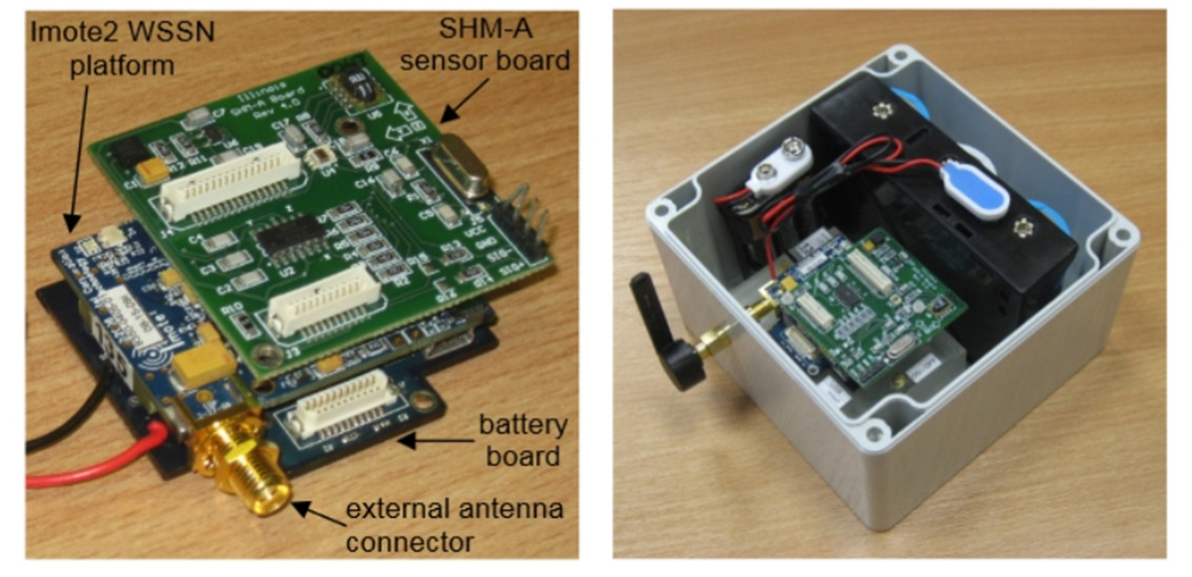
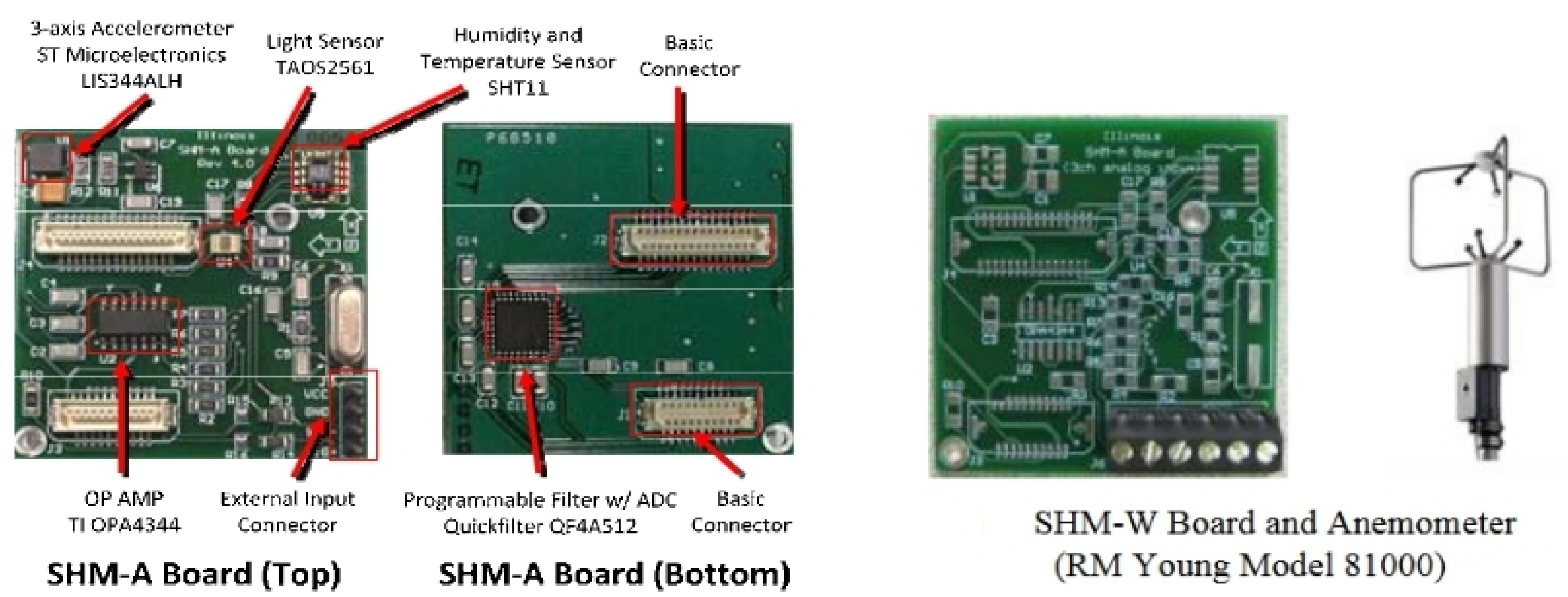
  75. de Battista, N.; Brownjohn, J.M.W. Use of Imote2 with SHM-A wireless smart sensor nodes. In Proceedings of the 5th World Conference on Structural Control and Monitoring (5WCSCM), Japan, Tokyo, 12–14 July 2010. [Google Scholar]
  76. Jang, S.; Jo, H.; Cho, S.; Mechitov, K.; Rice, J.A.; Sim, S.-H.; Jung, H.-J.; Yun, C.-B.; Spencer, B.F., Jr.; Agha, G. Structural health monitoring of a cable-stayed bridge using smart sensor technology: Deployment and evaluation. Smart Struct. Syst. 2010, 6, 439–459. [Google Scholar] [CrossRef] [Green Version]
  77. Weng, J.H.; Loh, C.H.; Lynch, J.P.; Lu, K.C.; Lin, P.Y.; Wang, Y. Output-Only Modal Identification of a Cable-Stayed Bridge Using Wireless Monitoring Systems. Engineering Structures; Elsevier: London, UK, 2008; Volume 30, pp. 1820–1830. [Google Scholar]
  78. Rice, J.A.; Mechitov, K.; Sim, S.-H.; Nagayama, T.; Jang, S.; Kim, R.; Spencer, B.F., Jr.; Agha, G.; Fujino, Y. Flexible smart sensor framework for autonomous structural health monitoring. Smart Struct. Syst. 2010, 6, 423–438. [Google Scholar] [CrossRef] [Green Version]
  79. Nagayama, T.; Jung, H.J.; Spencer, B.F.; Jang, S.; Mechitov, K.; Cho, S.; Ushita, M.; Yun, C.-B.; Agha, G.; Fujino, Y. International collaboration to develop a structural health monitoring system utilizing wireless smart sensor network and its deployment on a cable-stayed bridge. In Proceedings of the 5th World Conference on Structural Control and Monitoring (5WCSCM), Japan, Tokyo, 12–14 July 2010. [Google Scholar]
  80. Gu, H.; Jin, P.; Zhao, Y.; Lloyd, G.M.; Wang, M.L. Design and experimental validation of a wireless PVDF displacement sensor for structure monitoring. In Proceedings of the SPIE 5395, Non-destructive Detection and Measurement for Homeland Security II, San Diego, CA, USA, 2–6 March 2004; Volume 5395, pp. 91–99. [Google Scholar]
  81. Yu, Y.; Zhao, X.; Wang, Y.; Ou, J. A study on PVDF sensor using wireless experimental system for bridge structural local monitoring. Telecommun. Syst. 2011, 52, 2357–2366. [Google Scholar] [CrossRef]
  82. Stoczniowy, P. Za Kilka lat Rynek Morskich Farm Wiatrowych Przebije Wartość 16 Mld Dolarów. Available online: https://portalstoczniowy.pl/wiadomosci/za-kilka-lat-rynek-morskich-farm-wiatrowych-przebije-wartosc-16-mld-dolarow/ (accessed on 28 November 2020).
  83. Hildick-Smith, A. “Security for Critical Infrastructure SCADA Systems”, (SANS Reading Room, GSEC Practical Assignment, Version 1.4c, Option 1, February 2005). Available online: http://www.sans.org/reading_room/whitepapers/warfare/1644.php (accessed on 14 August 2021).
  84. Jung, S.; Song, J.-G.; Kim, S. Design on SCADA Test-bed and Security Device. Int. J. Multimed. Ubiquitous Eng. 2008, 3, 75–86. [Google Scholar]
  85. Surve, V. A Wireless Communication Device for Short Messages. Masters’s Thesis, Lund University, Lund, Sweden, 2006. Available online: www.certec.lth.se/doc/awireless.pdf (accessed on 20 September 2020).
  86. Taylor, K. Mobile Monitoring and Control Infrastructure. CSIRO. Available online: http://mobile.act.cmis.csiro.au (accessed on 14 March 2021).
  87. Technical Information Bulletin 04-1, Supervisory Control and Data Acquisition (SCADA) Systems, National Communications System, NCS TIB 04-1, October 2004. Available online: https://scadahacker.com/library/Documents/ICS_Basics/SCADA%20Basics%20-%20NCS%20TIB%2004-1.pdf (accessed on 20 November 2021).
  88. Goel, A.; Mishra, R.S. Remote Data Acquisition Using WirelessScada System. Int. J. Eng. 2009, 3, 58. [Google Scholar]
  89. Wireless Communications in SCADA Systems, USAT Corp. Report No: 888-550-8728. Available online: www.usatcorp.com (accessed on 16 August 2021).
  90. Sanchez-Iborra, R.; Gómez, A.S.; Ballesta-Viñas, J.; Cano, M.-D.; Skarmeta, A.F. Performance Evaluation of LoRa Considering Scenario Conditions. Sensors 2018, 18, 772. [Google Scholar] [CrossRef] [Green Version]
  91. Corporation, Semtech. Semtech Enables IoT of the Future with Next Generation LoRa Platform; GlobeNewswire News Room, 2018; Available online: https://www.globenewswire.com/news-release/2018/01/08/1285003/0/en/Semtech-Enables-IoT-of-the-Future-with-Next-Generation-LoRa-Platform.html (accessed on 25 November 2021).
  92. How to Transition to Wireless SCADA. Available online: https://www.link-labs.com/blog/how-to-transition-to-wireless-scada (accessed on 20 August 2021).
  93. Kim, D.-Y.; Kim, Y.-C. Implementation of Small-Scale Wind Turbine Monitoring and Control System Based on Wireless Sensor Network. J. Korean Inst. Commun. Inf. Sci. 2015, 40, 1808–1818. [Google Scholar] [CrossRef] [Green Version]
  94. Jaishree, S.; Sathiyasekar, K.; Sonika, S. Wireless fault detection and preventive system for Small Wind Turbine. Int. J. Adv. Res. Electr. Electron. Instrum. Eng. 2014, 3, 2278–8875. [Google Scholar]
Figure 1. Basic diagram of wireless communication [1].
Inventions 07 00018 g001
Figure 2. ZigBee protocol architecture [6].
Inventions 07 00018 g002
Figure 3. WiMAX protocol architecture [7].
Inventions 07 00018 g003
Figure 4. Wireless sensor node architecture [30].
Inventions 07 00018 g004
Figure 5. Graphical representation of different wired sensors distribution all over the aircraft [33].
Inventions 07 00018 g005
Figure 6. Examples of placing RFID transponders on the airport apron.
Inventions 07 00018 g006
Figure 7. Civil engineering structures equipped with SHM systems using wireless sensor networks [52].
Inventions 07 00018 g007
Figure 8. The hierarchical wireless sensor network for structural health monitoring in bridge structures [66].
Inventions 07 00018 g008
Figure 9. Wireless smart sensor node, WSSN [75].
Inventions 07 00018 g009
Figure 10. Illinois SHM Project: structural health monitoring-acceleration (also known as SHM-A) sensor board: top (left), bottom (middle), and perspective view (right) [78].
Inventions 07 00018 g010
Figure 11. Hardware units of SHM-A(left) and SHM-W board wireless smart sensors (right) [79].
Inventions 07 00018 g011
Figure 12. Wind turbine farm [82].
Inventions 07 00018 g012
Figure 13. Block diagram of wireless SCADA [88].
Inventions 07 00018 g013
Figure 14. Innovative wind power plant.
Inventions 07 00018 g014
Table 1. Comparison of selected parameters of different wireless systems.
TechnologyStandardMaximum BandwidthFrequencyRange
(Closed Space—Open Space)
License
WiFi [9,10]IEEE 802.11b
IEEE 802.11a
IEEE 802.11g
IEEE 802.11n
IEEE 802.11ac
IEEE 802.11ax
1–11 Mb/s
1.5–54 Mb/s
3–54 Mb/s
72–600 Mb/s
433–6933 Mb/s
600–9608 Mb/s
2.5 GHz
5 GHz
2.4 GHz
2.4/5 GHz
5 GHz
1–6 GHz
45–150 m
51–200 m
51–200 m
70–240 m
70–240 m
70–240 m
No
ZigBee [11]IEEE 802.15.4250 Kb/s784 MHz
868 MHz
915 MHz
2.4 GHz
10–300 mYes
Bluetooth [12]IEEE 802.15.1 v1
IEEE 802.15.1 v2
IEEE 802.15.1 v3
IEEE 802.15.1 v4
IEEE 802.15.1 v5
1 Mb/s
3 Mb/s
24–40 Mb/s
24 Mb/s
2–50 Mb/s
2.4 GHz100 m
100 m
100 m
100 m
300 m
No
RFID [13]ISO/IEC24791<1 Mb/s125 KHz
13.56 MHz
868 MHz
956 MHz
2.4 GHz
3 mNo
LoRa [14]IEEE 802.15.427–50 Kb/s433 MHz
868 MHz
915 MHz
923 MHz
up to 13 kmNo
SigFox [14]IEEE 802.15.4100 b/s433 MHz
868 MHz
915 MHz
up to 40 kmNo
NB-IOT [14]IEEE 802.15.4240 Kb/s800 MHz
900 MHz
and LTE bands
up to 10 kmYes
WirelessHART [15]IEEE 802.15.4250 Kb/s2.4 GHzup to 225 mNo
ISA100.11a [16]IEEE 802.15.4250 Kb/s2.4 GHzup to 150 mNo
WiMAX [17]IEEE 802.16
IEEE 802.16-2009
IEEE 802.16 m
37 Mb/s
83–141 Mb/s
110–365 Mb/s
2–11 Ghz<10 kmNo
Ultra-wideband (UWB) [18,19]ETSI EN 302 065
IEEE 802.15.4
50–100 Mb/s3.1–10.6 GHz10–150 mNo
WAIC [20]IEEE 802.15.4
IEEE C band
250 Kb/s–200 Mb/s4.2–4.5 GHz<100 mNo
Table 2. Comparison of WEP, WPA, and WPA2 security [21].
WEPWPAWPA2
Purpose of securityNeed to secure the sent signals in open spaceThe creation of new versions of wireless protocols forced the creation of a new type of securityInsufficient security in WPA.
Data encryption typeRivest Cipher 4 (RC4)TKIP—Temporal Key Integrity Protocol (using RC4)C.C.M.P.—A.E.S. based encryption protocol
Authentication (types)WEP-Open
WEP-Shared
WPA-PSK
WPA-Enterprise
WPA2-Personal
WPA2-Enterprise
Data integrityCRC-32Provided by Message Integrity CodeProvided by CBC-MAC (cipher block chaining message authentication code)
Technology weaknessesVery vulnerable to DoS attacks. Now, this security is broken.Vulnerable to DoS attacks and key reinstallation attack (KRACK.)Vulnerable to DoS attacks and key reinstallation attack (KRACK.)
Ease of technology implementationVery easy to set upWPA-Enterprise requires an authentication server configurationWPA2-Enterprise requires an authentication server configuration
Protection against attacks based on the replay methodNo securityPacket sequence counter is implementedThe new 48-bit vector IV acts as a frame counter
Publisher’s Note: MDPI stays neutral with regard to jurisdictional claims in published maps and institutional affiliations.

