Article

Biologically Inspired Intra-Uterine Nanofluid Flow under the Suspension of Magnetized Gold (Au) Nanoparticles: Applications in Nanomedicine

by
Muhammad Mubashir Bhatti
College of Mathematics and Systems Science, Shandong University of Science and Technology, Qingdao 266590, China
Inventions 2021, 6(2), 28; https://doi.org/10.3390/inventions6020028
Submission received: 18 February 2021 / Revised: 12 April 2021 / Accepted: 13 April 2021 / Published: 15 April 2021
(This article belongs to the Special Issue Recent Trends in Nanofluids - II)

Abstract

:
The present analysis deals with the intra-uterine nanofluid flow of a Jeffrey fluid through a finite asymmetric channel filled with gold nanoparticles. Gold nanoparticles are helpful in biomedicine to treat various diseases and locate blood flow motion through tiny vessels. The governing fluid is electrically conducting due to the presence of an extrinsic magnetic field while the magnetic Reynolds number is small; therefore, the induced magnetic effects are neglected. The thermal radiation and viscous dissipation effects are also contemplated with the energy equation. The lubrication approach has been utilized by taking a long wavelength and ignoring the inertial forces. The formulated equations are coupled and nonlinear; therefore, a perturbation approach is used to derive the series results. The results are obtained up to the second-order and plotted against various parameters for velocity mechanism, trapping profile, pressure rise, and temperature profile.

1. Introduction

Peristaltic flows occur due to the movement of waves along the stretchable (or flexible) walls through a channel. These flows give a well-organized way for sanitary fluid motion; therefore, they are examined in various industrial processes. In biomedical and physiological applications, peristaltic flows are beneficial to propagate blood through small vessels and artificial blood devices. Two engrossing mechanisms related to peristaltic flows are fluid trapping and material reflux. The trapping mechanism is the occurrence and downstream propagation of free eddies (also known as boluses). The material reflux is associated with the net upstream convection of fluid particles in opposition to the moving boundary waves. These two mechanisms have great importance because they are accountable for forming the thrombus in blood and bacteria’s pathological movement. Therefore, initially various authors determined peristaltic flows in different geometrical conditions for simple fluid models [1,2,3,4,5,6,7,8].
For the last several years, nanotechnology has played a fascinating role in various fields of science. Nanotechnology has performed as a bridge between physical and biological sciences by employing nano-based structures and nano-phases in distinct areas of science [9], especially in nanomedicine and drug-delivery systems based on nanotechnology, in which such kinds of particles are of paramount interest [10,11]. The size of the nanoparticles lies in the range of 1 to 100 nm, which significantly affects the frontiers of nanomedicine initiated from microfluidics, biosensors, drug delivery, and tissue engineering [12,13,14]. Nanotechnology applies therapeutic agents to manufacture medicine at the nanoscale level. The field of nano-biomedicine [15] includes biosensors, tissue engineering, drug delivery, nanobiotechnology, etc. Nanoparticles are designed at the molecular or atomic level; therefore, they can travel freely in the human body compared to other materials of a larger size. Nanoparticles reveal unique chemical, magnetic, electrical, biological, structural, and mechanical properties.
In addition, gold nanoparticles have a notable performance in treating various diseases in the human body. They have an important class due to their distinctive physiochemical features, i.e., the adsorption of near-infrared light producing thermal energy helps treat various diseases [16,17,18] through methods such as thermal therapy, contrast agents, radiosensitizers, tumor treatment, and cancer therapy. Recently, scientists have discovered that gold nanoparticles (size < 100 nm) are also beneficial for locating the blood flow through the tiny vessels in the human body [19]. The ability to locate the blood flow through tiny vessels helps to obtain indispensable information to comprehend the disease process, i.e., vascular inflammation and thrombosis.
Magnetized nanoparticles have gained attention in nanomedicine and analytical sensing over the past two decades due to the interaction of magnetic nanomaterials with field gradients and magnetic fields. The interaction between magnetic fields and magnetized nanoparticles means that (i) the position of magnetized nanoparticles can be controlled using magnets [20]; (ii) a variable magnetic field is beneficial for heating the particles, so that they can be applied in nanomedicine [21]; (iii) the magnetic features of magnetic nanoparticles will produce an impact on the magnetic fields so that they can be used as contrast agents in magnetic resonance imaging [22,23]. Applications of magnetized gold-coated nanoparticles include targeted drug delivery [24,25], downstream processing [26], and contrast agents [27]. The reason behind multiple applications of magnetic gold nanoparticles is they are highly adaptable; the magnetic and optical features of these particles can be modulated and customized to the applications by changing the shape, size, surface modification, and gold shell thickness.
Eldabe et al. [28] used a Carreau fluid model to examine the mechanism of gold nanoparticles propagating peristaltically through a non-Darcian porous medium. Prakash et al. [29] examined the behavior of nanofluid flow through a porous channel using a blood flow model. Ellahi et al. [30] inspected the couple stress fluid as blood under the suspension of nanoparticles in the presence of activation energy and a chemical reaction. Mekheimer et al. [31] scrutinized the behavior of gold nanoparticles using a peristaltic blood flow mechanism through an artery having overlapping stenosis. Bibi and Xu [32] elaborated the peristaltic mechanism of Carreau nanofluid flow with hybrid models under heterogeneous/homogenous reactions. Sadaf and Abdelsalam [33] explored the adverse impact of hybrid nanofluid through an annulus with convective and wavy conditions. Asproulis and Dimitris Drikakis [34] studied prototype flows, i.e., the slip Couette flow with heat transfer and the isothermal Couette flow with slip boundary conditions. They proposed a new artificial neural-network-based coupling method. This method inherits properties of the embedded framework and enhance the computational efficiency of the embedded modeling approaches utilizing artificial intelligence techniques. Some major studies on the nanoparticles with blood flow are given in refs. [35,36,37,38,39,40].
After reviewing various applications of magnetized gold nanoparticles, the main objective of this study is to examine the biologically inspired intra-uterine Jeffrey fluid flow under the suspension of magnetic gold nanoparticles through an asymmetric channel. Gold nanoparticles are helpful in biomedicine for treating various diseases and locating the motion of blood flow through tiny vessels. The fluid is electrically conducting due to the influence of the extrinsic magnetic field. The energy equation is contemplated with viscous and thermal radiation effects. The lubrication theory is applied to formulate mathematical modeling. The resulting equations are finalized by ignoring the inertial forces, and the Reynolds number is contemplated to be very low. A perturbation approach is used to obtain the solutions. The solutions are presented up to second-order approximation. Numerical computation is used to inspect the pumping characteristics.

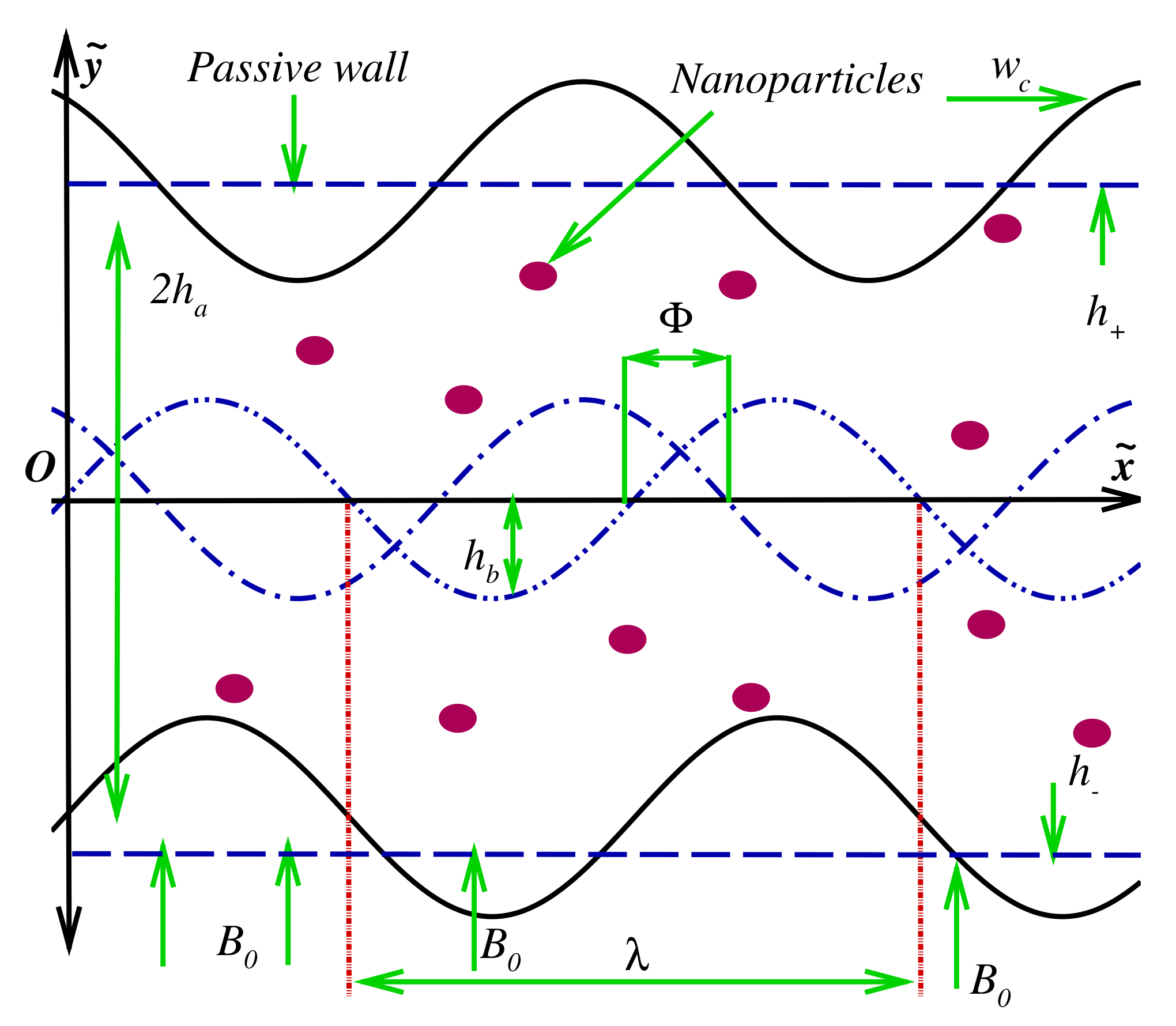
2. Modeling of Two-Dimensional Intra-Uterine Nanofluid Flow

Consider a asymmetric intra-uterine motion (peristaltic in nature) of a Jeffery nanofluid through a finite channel under the suspension of gold nanoparticles. The Jeffrey fluid model is contemplated as a blood. The fluid is propagating in an axial direction ( x ˜ axis), while the y ˜ axis is allocated along the normal direction as given in Figure 1. The fluid is irrotational, incompressible, and electrically conducting in the existence of an extrinsic magnetic field. A consistent magnetic field is contemplated in the normal direction while taking the magnetic Reynolds number to be very low. The mathematical expression for the time-dependent fluid–wall interface is defined as
h = h a + η , η = h b cos 2 π λ ( x ˜ w c t ) Φ 2 ,
h + = h a + η + , η + = h b cos 2 π λ ( x ˜ w c t ) + Φ 2 ,
where 2 h a denotes the unperturbed width of the channel; h b denotes the amplitude of lower and upper waves; w c is the wave speed; t denotes the time; λ represents the wavelength. The channel width is smaller compared with the wavelength, i.e., h a / λ 1 . The phase difference is denoted by Φ having range 0 Φ π , where the symmetric contractions can be recovered by taking Φ = π .
The proposed Jeffrey fluid model is defined as
ς = μ n f 1 + ω 1 χ + ω 2 χ ,
where μ is the viscosity; ω 1 is the ratio of the relaxation to retardation time; ω 2 represents the delay time; n f denotes the nanofluid; χ is the shear rate and ( ) denotes the differentiation with the time. The proposed models against continuity, momentum, and energy equations in two-dimensions are defined as [41,42,43]:
· W ˜ = 0 ,
ρ n f W ˜ t + W ˜ · W ˜ = P + ς + g ( ρ β ) n f T ¯ T ¯ 0 + J × B ,
where J × B = σ n f B 0 U ¯ , 0 , 0 ; the velocity field is defined as W ˜ = U ¯ , V ¯ , 0 ; σ is the electrical conductivity; ρ denotes the density; P is the pressure; β denotes the thermal expansion coefficient; T ¯ is the temperature; the current density is denoted by J ; and B ( = B 0 ) is the magnetic field.
The energy equation with thermal radiation and viscous dissipation effects is defined as
ρ c p h n f T ¯ t + W ˜ · T ¯ = κ n f 2 T ¯ + ς · W ˜ q r y + J · J σ n f ,
where κ n f is the nanofluid’s thermal conductivity; ρ c p n f is the specific heat capacity of the nanofluid; and q r is the radiative heat flux, which is defined as
q r = 16 σ ˜ T ¯ 3 3 k ˜ T ¯ y ,
where σ ˜ , k ˜ are the Stefan–Boltzmann constant and the mean absorption coefficient.
The boundary conditions are defined as
U ¯ = 0 , T ¯ = T ¯ 0 , y = h ,
U ¯ = 0 , T ¯ = T ¯ 1 , y = h + .
The thermo-physical properties of effective density, heat capacity, effective dynamic viscosity, thermal conductivity, electrical conductivity, and the thermal expansion coefficient are defined as
ρ n f = ( 1 ϑ ) ρ f + ϑ ρ n p , ρ c p n f = ρ c p f ( 1 ϑ ) + ϑ ρ c p n p , μ n f = μ f ( 1 ϑ ) 2.5 , κ n f κ f = κ n p + 2 κ f 2 ϑ ( κ f κ n p ) κ n p + 2 κ f + ϑ ( κ f κ n p ) , σ n f = σ f × σ n p ( 1 + 2 ϑ ) + 2 σ f ( 1 ϑ ) σ n p ( 1 ϑ ) + σ f ( 2 + ϑ ) , ρ β n f = ρ β f ( 1 ϑ ) + ϑ ρ β n p .
We now define the dimensionless variables using a lubrication approach. These variables are described as
X = x ˜ λ , Y = y ˜ b , H = h h a , H + = h + h a , U = U ¯ w c , V = V ¯ w c δ , δ = b λ , T = T ¯ T ¯ 0 T ¯ 1 T ¯ 0 , P = b 2 P μ f w c λ , t = w c t λ .
Employing the dimensionless variables of Equation (11) into the governing equations, we obtain the following coupled systems (after ignoring the inertial forces):
D 1 1 + ω 1 2 U Y 2 D 2 H a 2 U + D 3 T g T P X = 0 ,
P Y = 0 ,
2 T Y 2 + B r D 1 ( D 4 + T r ) ( 1 + ω 1 ) U Y 2 + D 2 B r H a 2 D 4 + T r U 2 = 0 ,
where H a is the Hartmann number; T g is the thermal Grashof number; B r is the Brinkman number; T r is the thermal radiation, and D 1 , D 2 , D 3 , D 4 are defined as
H a = σ f μ f B 0 b , E c = w c 2 c p f T ¯ 1 T ¯ 0 , B r = E c × P r , G r = ( ρ β ) f g b 2 μ f w c T ¯ 1 T ¯ 0 , P r = ν f ( ρ c p ) f κ f , T r = 16 σ ˜ T ¯ 3 3 k ˜ κ f , D 1 = μ n f μ f , D 2 = σ n f σ f , D 3 = ( ρ β ) n f ( ρ β ) f , D 4 = κ n f κ f .
Their boundary conditions reduce to the following form:
U = 0 , T = 0 , at Y = H = 1 + Ψ cos 2 π ( X t ) Φ 2 ,
U = 0 , T = 1 , at Y = H + = 1 + Ψ cos 2 π ( X t ) + Φ 2 ,
where Ψ = h b / h a denotes the amplitude ratio.

3. Series Solutions Via Perturbation Approach

To find the solutions of Equations (12)–(14), we employ a perturbation approach. The perturbation approach was first introduced by J.H. He [44]. The proposed methodology has been applied to many linear and nonlinear problems [45,46]. Defining the perturbation process for the formulated Equations (12)–(14):
p u , ξ = ( 1 ξ ) L U ( u ) L U ( U 0 ) + ξ L U ( u ) D 2 D 1 H a 2 u + D 3 D 1 T g θ 1 D 1 d P d X ,
p θ , ξ = ( 1 ξ ) L T ( θ ) L T ( T 0 ) + ξ L T ( θ ) + B r D 1 ( D 4 + T r ) ( 1 + ω 1 ) u Y 2 + D 2 B r H a 2 D 4 + T r u 2 ,
where L U , L T are the linear operators, which are defined as
L U = 1 1 + ω 1 2 Y 2 , L T = 2 Y 2 ,
with their initial guesses
U 0 = ( Y H ) ( Y + H + ) 2 ( 1 + ω 1 ) , T 0 = H Y H + H + .
Defining the expansions
u = u 0 + ξ u 1 + ξ 2 u 2 + ,
θ = θ 0 + ξ θ 1 + ξ 2 θ 2 + .
Using Equations (22) and (23) in the governing Equations (18) and (19), we obtain a set of differential equations at each order of approximation.

3.1. Zeroth-Order System

The zeroth-order system is found as
L U ( u 0 ) L U ( U 0 ) = 0 , u 0 = 0 at Y = H , u 0 = 0 at Y = H + ,
L T ( θ 0 ) L T ( T 0 ) = 0 , θ 0 = 0 at Y = H , θ 0 = 1 at Y = H + ,
The zeroth-order solutions are obtained as
u 0 = U 0 = ( Y H ) ( Y H + ) 2 ( 1 + ω 1 ) ,
θ 0 = T 0 = H Y H + H + ,

3.2. First-Order System

The first-order system is found as
L U ( u 1 ) + L U ( U 0 ) D 2 D 1 H a 2 u 0 + D 3 D 1 T g θ 0 1 D 1 P X u 1 = 0 at Y = H , u 1 = 0 at Y = H + ,
L T ( θ 1 ) + L T ( T 0 ) + B r D 1 ( D 4 + T r ) ( 1 + ω 1 ) u 0 Y 2 + D 2 B r H a 2 D 4 + T r u 0 2 , θ 1 = 0 at Y = H , θ 1 = 0 at Y = H + .
The first-order solutions are obtained as
u 1 = u ¯ 0 + u ¯ 1 y + u ¯ 2 y 2 + u ¯ 3 y 3 + u ¯ 4 y 4 , θ 0 = θ ¯ 0 + θ ¯ 1 y + θ ¯ 2 y 2 + θ ¯ 3 y 3 + θ ¯ 4 y 4 + θ ¯ 5 y 5 + θ ¯ 6 y 6 .

3.3. Second-Order System

The second-order system is found as
L U ( u 2 ) D 2 D 1 H a 2 u 1 + D 3 D 1 T g θ 1 u 2 = 0 at Y = H , u 2 = 0 at Y = H + ,
L T ( θ 2 ) + 2 B r D 1 ( D 4 + T r ) ( 1 + ω 1 ) u 0 Y u 1 Y + D 2 B r H a 2 D 4 + T r u 1 2 , θ 2 = 0 at Y = H , θ 2 = 0 at Y = H + .
The second-order solutions are obtained as
u 2 = u ¯ 5 + u ¯ 6 y + u ¯ 7 y 2 + u ¯ 8 y 3 + u ¯ 9 y 4 + u ¯ 10 y 5 + u ¯ 11 y 6 + u ¯ 12 y 7 + u ¯ 13 y 8 , θ 2 = θ ¯ 7 + θ ¯ 8 y + θ ¯ 9 y 2 + θ ¯ 10 y 3 + θ ¯ 11 y 4 + θ ¯ 12 y 5 + θ ¯ 13 y 6 + θ ¯ 14 y 7 + θ ¯ 15 y 8 + θ ¯ 16 y 9 + θ ¯ 17 y 10 .
The constants, i.e., u ¯ n ; θ ¯ n , n = 0 , 1 , 2 , , in the above equations are too long, therefore, we omit the constant values here. These constants can easily be found from the computational software Mathematica. We will stop our calculations here and proceed towards the graphical results.
Using the properties of the perturbation approach [44,46], i.e., ξ 1 , the solutions in the final form can be written as
U = u = u 0 + u 1 + u 2 + ,
T = θ = θ 0 + θ 1 + θ 2 + .
The instantaneous volumetric flow rate is calculated using the following expression:
Q = H H + U d Y .
The pressure rise is calculated numerically with the help of given expression
Δ P = 0 1 d P d X d X .

4. Graphical Outcomes and Discussion

This part deals with the graphical outcomes of the different parameters on velocity curves U, temperature distribution T, pressure rise profile Δ P , and trapping mechanism. We have selected the following parametric values for the computational procedure, for instance Ψ = 0.1 , H a = 0.5 , ω 1 = 0.5 , B r = 2 , T r = 2 , ϑ = 0.1 , and Q = 2 , whereas the thermo-physical properties of the nanofluid and blood are given in Table 1 [47].

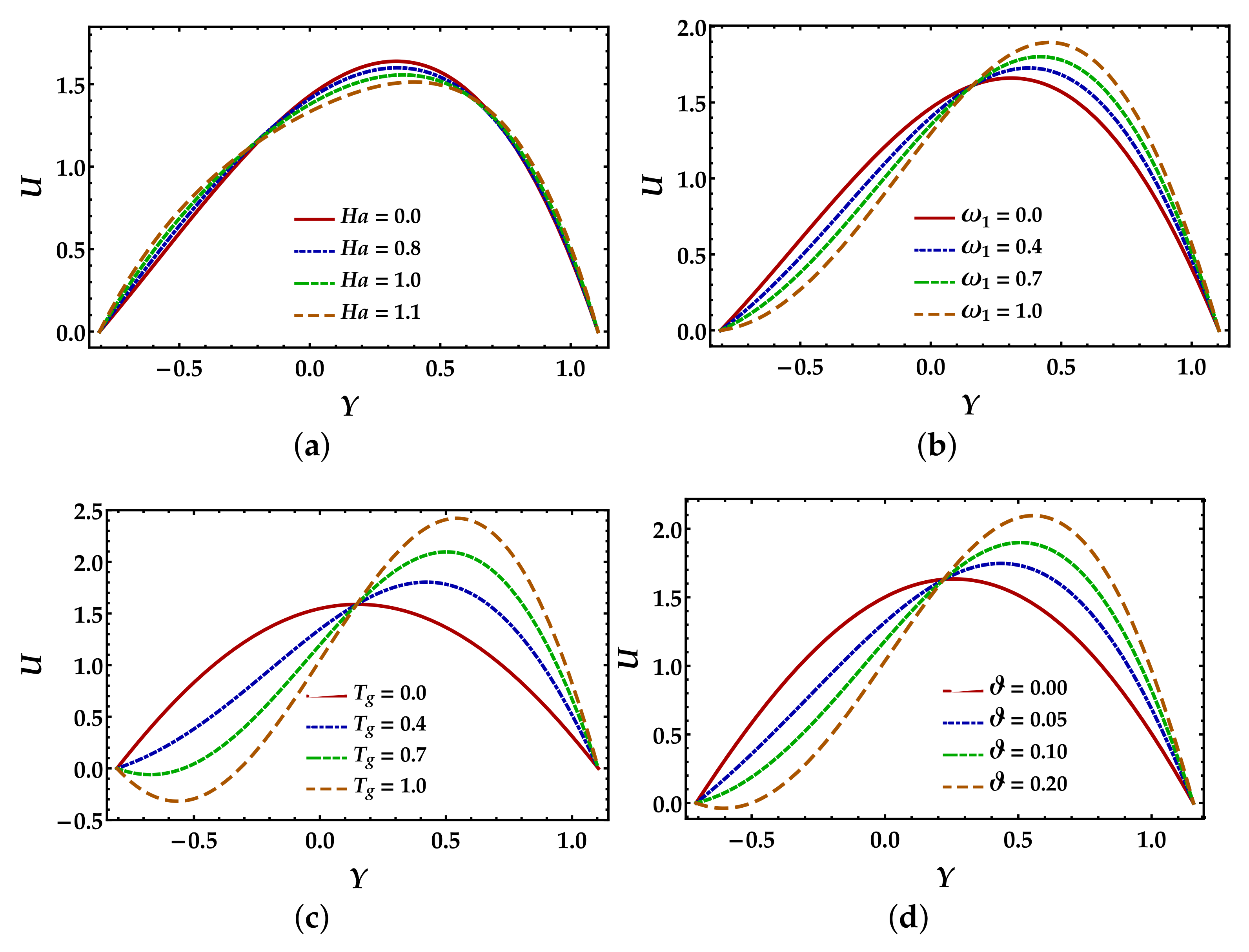
4.1. Velocity Mechanism

Figure 2a was plotted to see the behavior of magnetic field H a on the velocity profile. It is noted here that closer to the walls of the channel, the effects are negligible or minimal; however, in the middle of the channel, the magnetic field shows resistance to the fluid motion. Figure 2b was plotted to determine the Jeffrey fluid parameter on velocity curves. It can be noted here that the Jeffrey fluid parameter ω 1 indicates dual behavior. When Y < 0.2 , it opposes the fluid motion, whereas when Y > 0.2 , it increases. It is essential to describe here that the Newtonian fluid results can be achieved by contemplating ω 1 = 0 . It is shown from Figure 2c that the thermal Grashof number T g boosts the velocity profile when Y > 0.2 , whereas in the remaining region, its behavior is converse. It is shown in Figure 2d that the velocity profile has a dual mechanism against the nanoparticle volume fraction ϑ . The velocity profile is increasing closer to the wall, but on the other wall, it is decreasing.

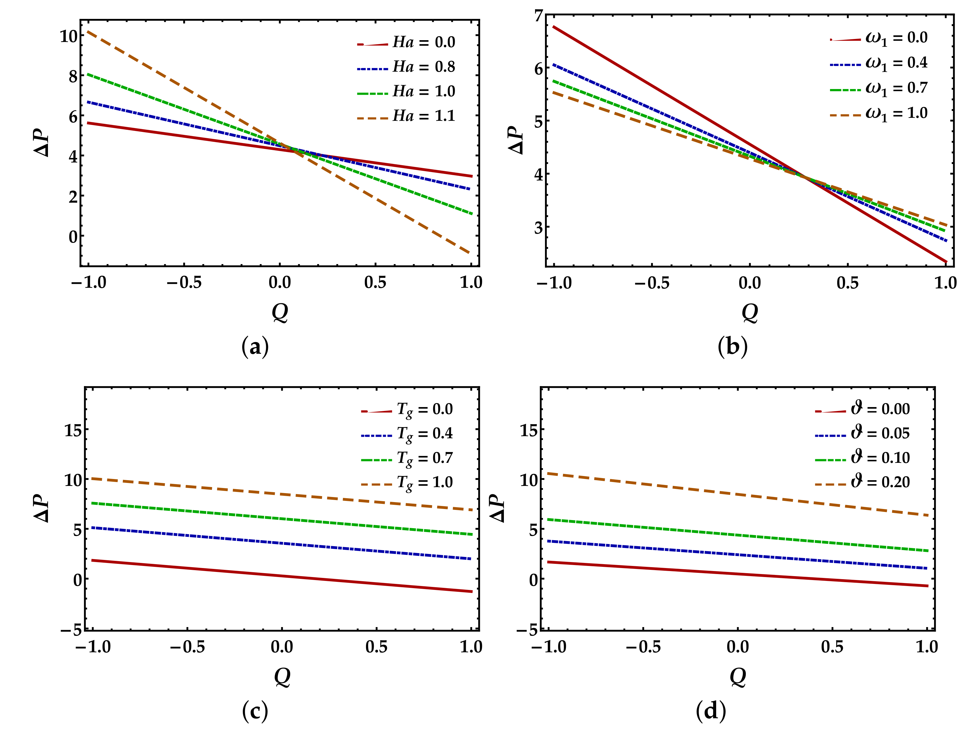
4.2. Pressure Rise Profile

Figure 3 shows the pressure rise profile Δ P versus volumetric flow rate Q against different parameters. In Figure 3a, we can see that the Hartmann number H a enhances the flow rate in the retrograde pumping zone Q < 0 , Δ P > 0 , whereas the behavior is converse in the peristaltic pumping Q > 0 , Δ P > 0 and co-pumping zones Q > 0 , Δ P < 0 . Similar behavior for the three-dimensional flow of the Jeffrey fluid model was observed by Ellahi et al. [48]. In Figure 3b, we can see that pumping rate diminishes in the retrograde pumping zone against the higher values of Jeffery fluid parameter ω 1 , while it increases in the peristaltic pumping zone. The thermal Grashof number T g and the particle volume fraction ϑ show similar and promising results on the pressure rise (see Figure 3c,d). We can see that both parameters uniformly enhance the pressure rise along the whole region Q [ 1 , 1 ] .

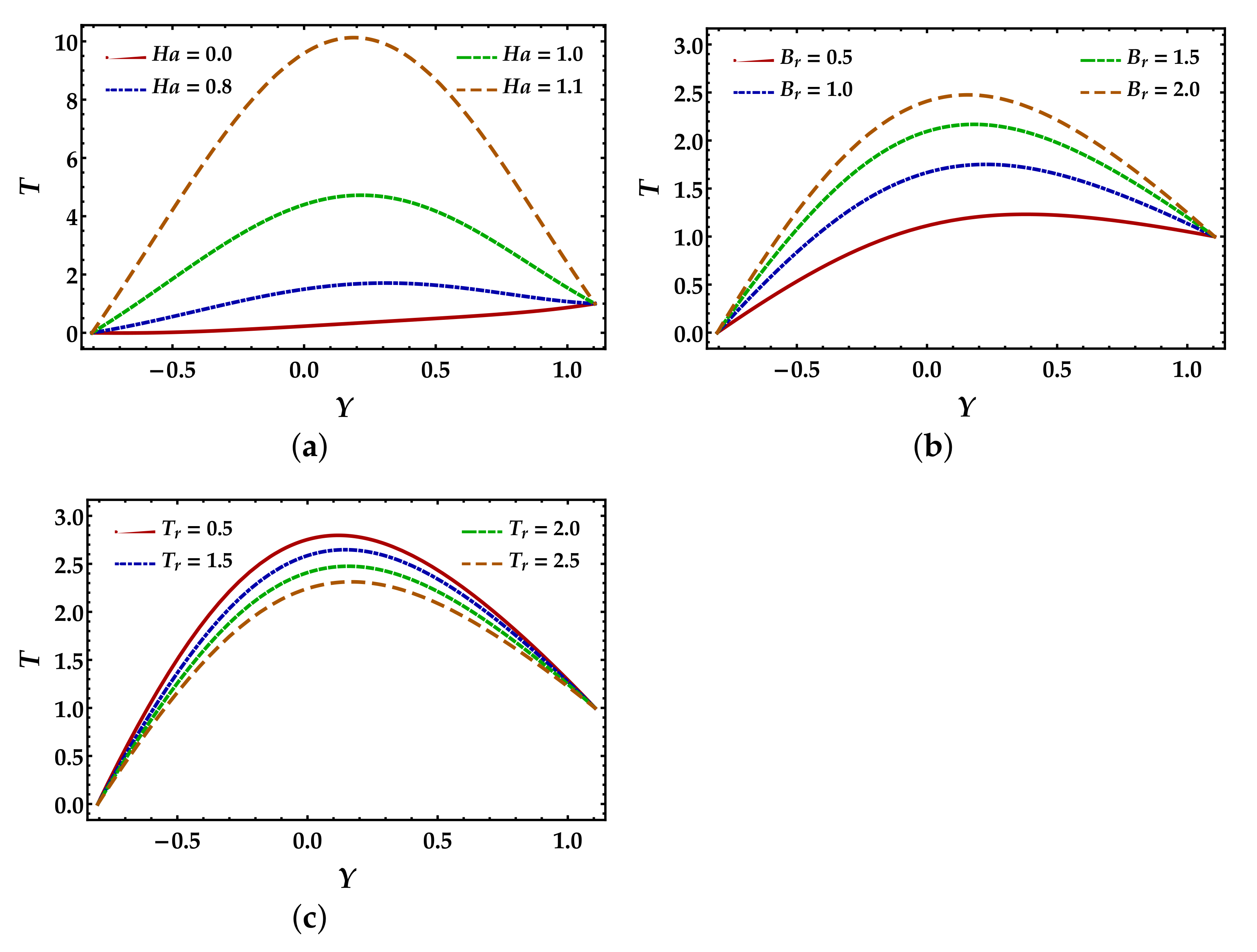
4.3. Temperature Distribution

Figure 4 was plotted to examine the mechanism of temperature curves against the Hartmann number H a , Brinkman number B r , and thermal radiation parameter T r . We can observe in Figure 4a that the magnetic field significantly enhances the temperature profile and shows a parabolic shape. Physically, strengthening the values of the Hartmann number tends to raise the electromagnetic forces, which significantly boost the temperature profile. It is observed in Figure 4b that the Brinkman number B r significantly uplifts the temperature profile. Increasing the values of the Brinkman number tends to reduce the conduction process reductions that occur due to viscous dissipation, which causes augmentation in the temperature profile. It is noted in Figure 4c that the temperature profile decreases in the parabolic shape due to an increment in the thermal radiation parameter.

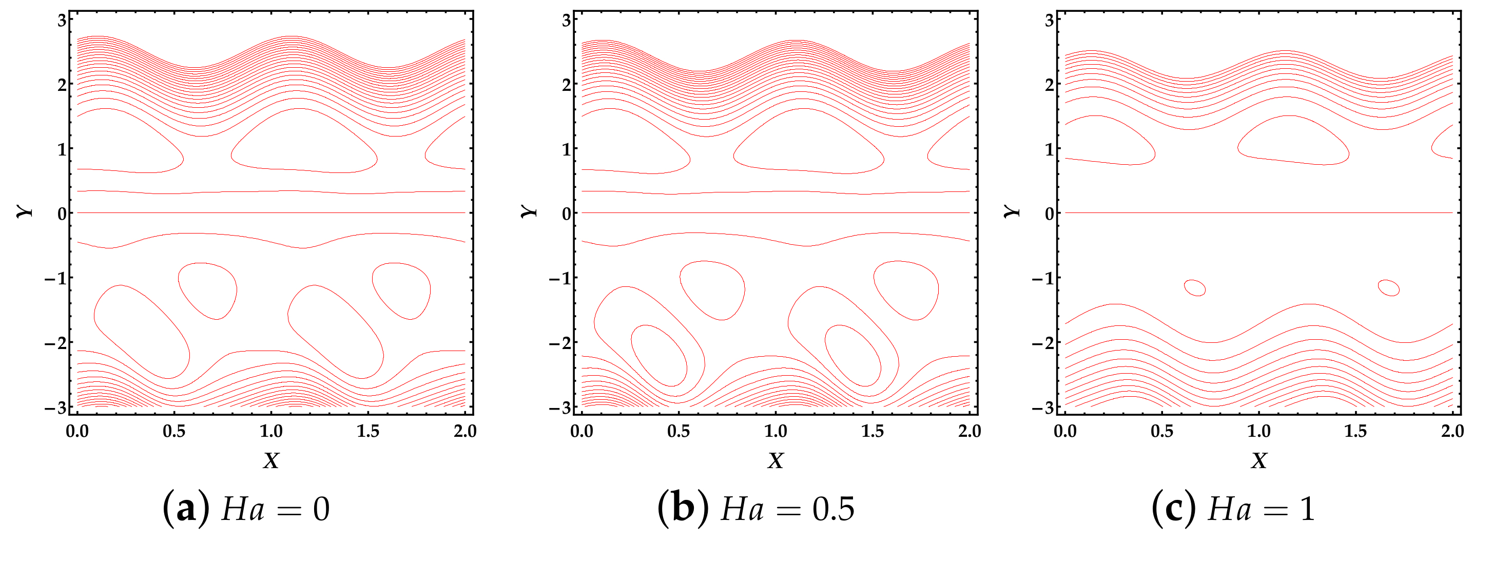
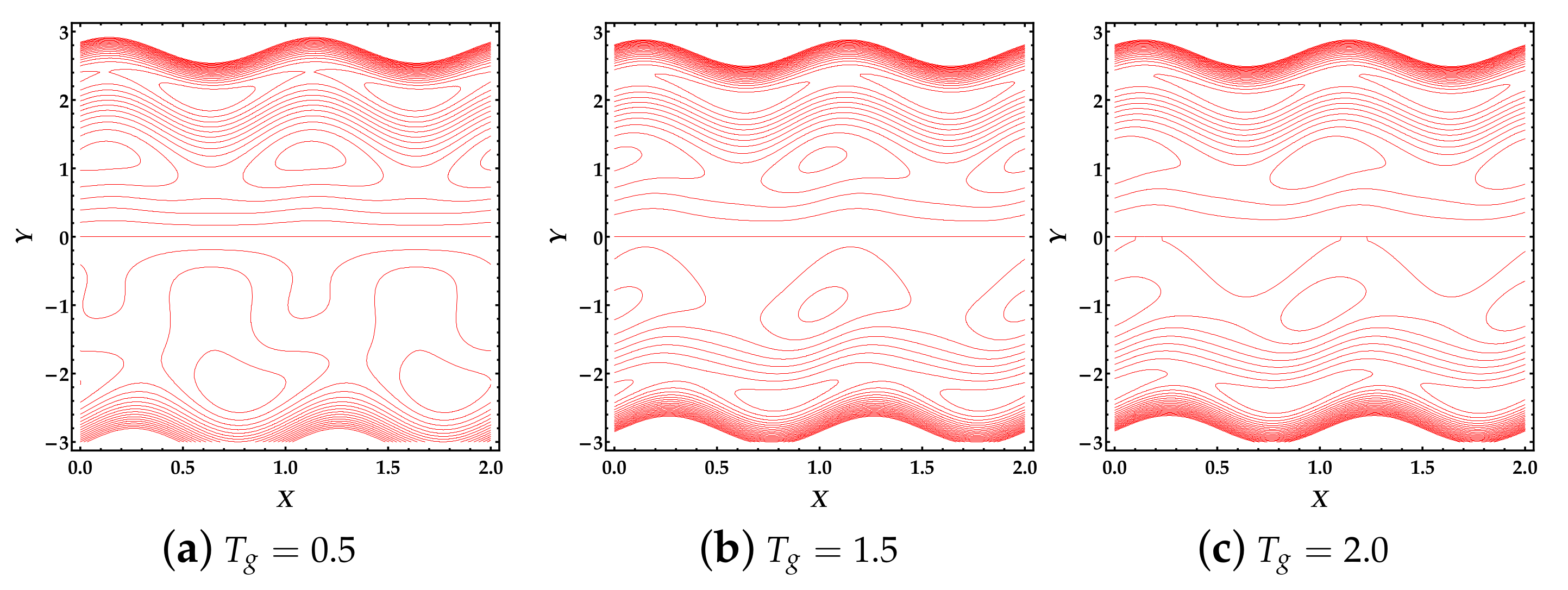
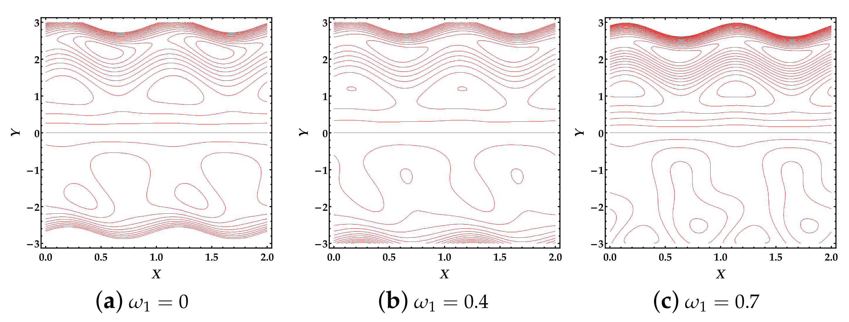
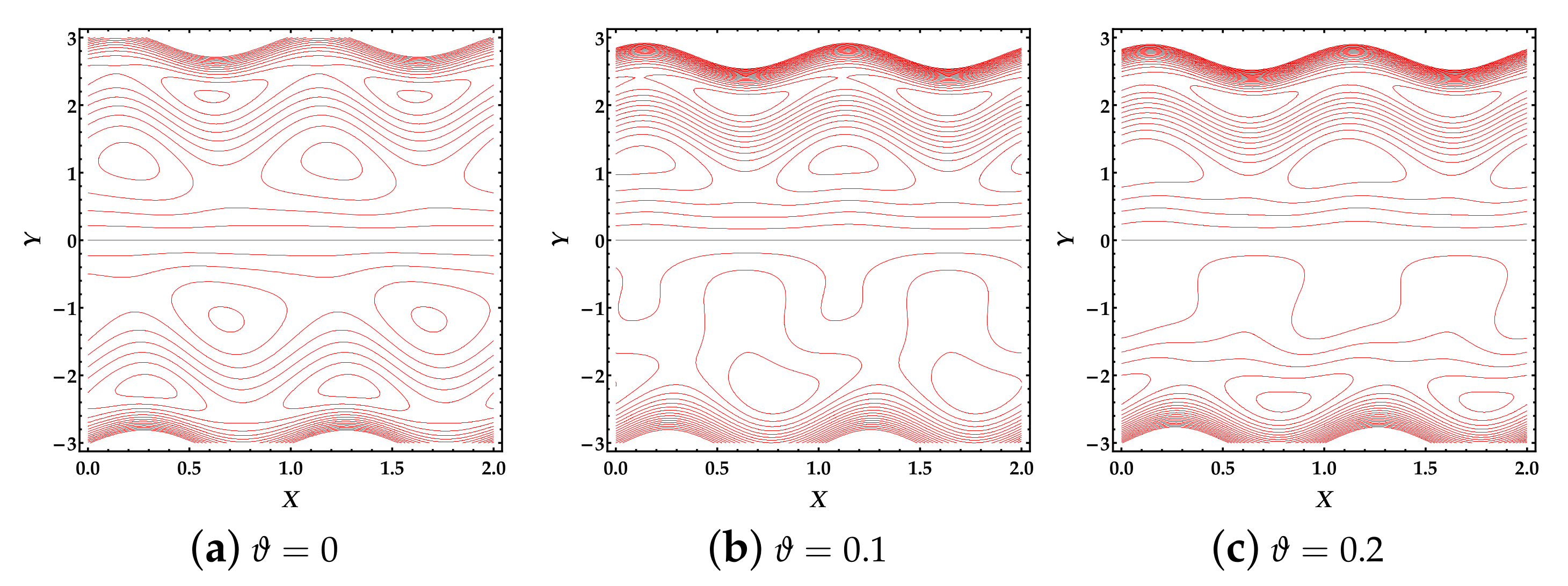
4.4. Trapping Phenomena

The following figures were plotted to analyze the behavior of the trapping process by plotting contours. Trapping is known as the internally moving free eddies (or bolus) bounded by streamlines. Physiologically, this mechanism has tremendous importance because it helps the production of thrombus in the blood and a pathological transport of bacteria. Figure 5 shows the effects of the Hartmann number H a on the trapping process. It is noted here that increasing values of Hartmann number H a oppose the generation of free eddies and the streamlines dispersed. In Figure 6, we observe that by increasing the values of the thermal Grashof number T g , the free eddies reduce as well as the streamlines scattered, which also affects the magnitude of the free eddies. It can be seen from Figure 7 that the Jeffrey fluid parameter ω 1 reveals versatile behavior on the trapping profile. Due to an increment in the values of ω 1 , we found that new free eddies of different shapes occur as well as a few free eddies disappearing. Lastly, by enhancing the values of particle volume fraction ϑ , the free eddies changes in shape and reduce in number as plotted in Figure 8.

5. Conclusions

We have examined the behavior of gold nanoparticles suspended in a Jeffrey fluid propagating peristaltically through an asymmetric channel. The proposed fluid is incompressible, irrotational, and electrically conducting due to the extrinsic uniform magnetic field. The impact of thermal radiation and viscous dissipation was also contemplated with the energy equation. The lubrication approach was utilized to formulate the mathematical modeling and then the formulated equations were finalized using long wavelength and ignoring the inertial forces. A perturbation approach was used to solve the coupled nonlinear differential equations. The series solutions up to second-order approximation were presented, while a numerical computation was performed to determine the expression for pressure rise. Some important outcomes from the current computational results are summarized as follows.
(i)
The presence of a magnetic field substantially opposes the flow in the central zone of the channel. At the same time, closer to the walls, the behavior seems to be negligible or very small.
(ii)
The fluid parameter, particle volume fraction, and thermal Grashof number show a reduction in the fluid motion when Y < 0.1 , whereas a significant increment is observed when Y > 0.1 .
(iii)
The pressure rise reveals an increasing behavior against the thermal Grashof number and particle volume fraction in the retrograde and peristaltic pumping zones. In contrast, the fluid parameter and Hartmann number show a converse process in both regions.
(iv)
Temperature profile remarkably rises due to strengthening in the magnetic field and Brinkmann number, while the thermal radiation opposes the increment of the temperature profile.
(v)
We can see that the magnetic field tends to diminish the free eddies, while the thermal Grashof number significantly affects the magnitude and number of free eddies.
(vi)
We also found that the particle volume fraction and fluid parameter markedly change the shape and the number of free eddies.
We have ignored the different effects during the present investigation, i.e., porosity, electric field, and induced magnetic field, which can be contemplated shortly using various fluid models.

Funding

This research received no external funding.

Institutional Review Board Statement

Not applicable.

Informed Consent Statement

Not applicable.

Data Availability Statement

Not applicable.

Conflicts of Interest

The author declares no conflict of interest.

References

  1. Tripathi, D. Numerical and analytical simulation of peristaltic flows of generalized Oldroyd-B fluids. Int. J. Numer. Methods Fluids 2011, 67, 1932–1943. [Google Scholar] [CrossRef]
  2. Tripathi, D.; Bég, O.A. A study on peristaltic flow of nanofluids: Application in drug delivery systems. Int. J. Heat Mass Transf. 2014, 70, 61–70. [Google Scholar] [CrossRef]
  3. Akbar, N.S.; Raza, M.; Ellahi, R. Influence of induced magnetic field and heat flux with the suspension of carbon nanotubes for the peristaltic flow in a permeable channel. J. Magn. Magn. Mater. 2015, 381, 405–415. [Google Scholar] [CrossRef]
  4. Tripathi, D.; Bhushan, S.; Bég, O.A. Transverse magnetic field driven modification in unsteady peristaltic transport with electrical double layer effects. Colloids Surf. Physicochem. Eng. Asp. 2016, 506, 32–39. [Google Scholar] [CrossRef]
  5. Fusi, L.; Farina, A. Peristaltic axisymmetric flow of a Bingham fluid. Appl. Math. Comput. 2018, 320, 1–15. [Google Scholar] [CrossRef]
  6. Alokaily, S.; Feigl, K.; Tanner, F.X. Characterization of peristaltic flow during the mixing process in a model human stomach. Phys. Fluids 2019, 31, 103105. [Google Scholar] [CrossRef]
  7. Rashid, M.; Ansar, K.; Nadeem, S. Effects of induced magnetic field for peristaltic flow of Williamson fluid in a curved channel. Phys. Stat. Mech. Appl. 2020, 553, 123979. [Google Scholar] [CrossRef]
  8. Romanò, F.; Suresh, V.; Galie, P.A.; Grotberg, J.B. Peristaltic flow in the glymphatic system. Sci. Rep. 2020, 10, 21065. [Google Scholar]
  9. Liu, Z.; Tabakman, S.; Welsher, K.; Dai, H. Carbon nanotubes in biology and medicine: In vitro and in vivo detection, imaging and drug delivery. Nano Res. 2009, 2, 85–120. [Google Scholar] [CrossRef] [Green Version]
  10. Orive, G.; Gascon, A.R.; Hernández, R.M.; Domínguez-Gil, A.; Pedraz, J.L. Techniques: New approaches to the delivery of biopharmaceuticals. Trends Pharmacol. Sci. 2004, 25, 382–387. [Google Scholar] [CrossRef]
  11. Razzacki, S.Z.; Thwar, P.K.; Yang, M.; Ugaz, V.M.; Burns, M.A. Integrated microsystems for controlled drug delivery. Adv. Drug Deliv. Rev. 2004, 56, 185–198. [Google Scholar] [CrossRef] [PubMed]
  12. M Saeed, A.; Najma, S.; Faiza, Q. Nanoparticles in delivery of cardiovascular drugs. Pak. J. Pharm. Sci. 2007, 20, 340–348. [Google Scholar]
  13. Patra, J.K.; Baek, K.H. Green nanobiotechnology: Factors affecting synthesis and characterization techniques. J. Nanomater. 2014, 2014, 417305. [Google Scholar] [CrossRef] [Green Version]
  14. Joseph, R.R.; Venkatraman, S.S. Drug delivery to the eye: What benefits do nanocarriers offer? Nanomedicine 2017, 12, 683–702. [Google Scholar] [CrossRef] [Green Version]
  15. Mirza, A.Z.; Siddiqui, F.A. Nanomedicine and drug delivery: A mini review. Int. Nano Lett. 2014, 4, 94. [Google Scholar] [CrossRef] [Green Version]
  16. Jain, S.; Hirst, D.; O’Sullivan, J. Gold nanoparticles as novel agents for cancer therapy. Br. J. Radiol. 2012, 85, 101–113. [Google Scholar] [CrossRef]
  17. Hussain, F.; Ellahi, R.; Zeeshan, A.; Vafai, K. Modelling study on heated couple stress fluid peristaltically conveying gold nanoparticles through coaxial tubes: A remedy for gland tumors and arthritis. J. Mol. Liq. 2018, 268, 149–155. [Google Scholar] [CrossRef]
  18. Abd Elmaboud, Y.; Mekheimer, K.S.; Emam, T.G. Numerical examination of gold nanoparticles as a drug carrier on peristaltic blood flow through physiological vessels: Cancer therapy treatment. BioNanoScience 2019, 9, 952–965. [Google Scholar] [CrossRef]
  19. Rogers, N.J.; Jeffery, H.C.; Claire, S.; Lewis, D.J.; Zikeli, G.; Hodges, N.J.; Egginton, S.; Nash, G.B.; Pikramenou, Z. Tailoring iridium luminescence and gold nanoparticle size for imaging of microvascular blood flow. Nanomedicine 2017, 12, 2725–2740. [Google Scholar] [CrossRef] [Green Version]
  20. Beveridge, J.S.; Stephens, J.R.; Williams, M.E. The use of magnetic nanoparticles in analytical chemistry. Annu. Rev. Anal. Chem. 2011, 4, 251–273. [Google Scholar] [CrossRef]
  21. Wang, J.; Zhou, Z.; Wang, L.; Wei, J.; Yang, H.; Yang, S.; Zhao, J. CoFe2O4@ MnFe2O4/polypyrrole nanocomposites for in vitro photothermal/magnetothermal combined therapy. RSC Adv. 2015, 5, 7349–7355. [Google Scholar] [CrossRef]
  22. Sun, C.; Lee, J.S.; Zhang, M. Magnetic nanoparticles in MR imaging and drug delivery. Adv. Drug Deliv. Rev. 2008, 60, 1252–1265. [Google Scholar] [CrossRef] [Green Version]
  23. Liong, M.; Lu, J.; Kovochich, M.; Xia, T.; Ruehm, S.G.; Nel, A.E.; Tamanoi, F.; Zink, J.I. Multifunctional inorganic nanoparticles for imaging, targeting, and drug delivery. ACS Nano 2008, 2, 889–896. [Google Scholar] [CrossRef] [Green Version]
  24. Kumagai, M.; Sarma, T.K.; Cabral, H.; Kaida, S.; Sekino, M.; Herlambang, N.; Osada, K.; Kano, M.R.; Nishiyama, N.; Kataoka, K. Enhanced in vivo Magnetic Resonance Imaging of Tumors by PEGylated Iron-Oxide–Gold Core–Shell Nanoparticles with Prolonged Blood Circulation Properties. Macromol. Rapid Commun. 2010, 31, 1521–1528. [Google Scholar] [CrossRef] [PubMed]
  25. Ahmad, T.; Bae, H.; Rhee, I.; Chang, Y.; Jin, S.U.; Hong, S. Gold-coated iron oxide nanoparticles as a T 2 contrast agent in magnetic resonance imaging. J. Nanosci. Nanotechnol. 2012, 12, 5132–5137. [Google Scholar] [CrossRef] [PubMed] [Green Version]
  26. Salehizadeh, H.; Hekmatian, E.; Sadeghi, M.; Kennedy, K. Synthesis and characterization of core-shell Fe3O4-gold-chitosan nanostructure. J. Nanobiotechnol. 2012, 10, 1–7. [Google Scholar] [CrossRef] [PubMed] [Green Version]
  27. Kayal, S.; Ramanujan, R.V. Anti-cancer drug loaded iron–gold core–shell nanoparticles (Fe@ Au) for magnetic drug targeting. J. Nanosci. Nanotechnol. 2010, 10, 5527–5539. [Google Scholar] [CrossRef] [PubMed]
  28. Eldabe, N.; Moatimid, G.; El-Shekhipy, A.; Aballah, N.F. Peristaltic blood flow with gold nanoparticles on a carreau nanofluid through a non-darcian porous medium. J. Biomater. Nanobiotechnol. 2018, 9, 290–306. [Google Scholar] [CrossRef] [Green Version]
  29. Prakash, J.; Tripathi, D.; Tiwari, A.K.; Sait, S.M.; Ellahi, R. Peristaltic pumping of nanofluids through a tapered channel in a porous environment: Applications in blood flow. Symmetry 2019, 11, 868. [Google Scholar] [CrossRef] [Green Version]
  30. Ellahi, R.; Zeeshan, A.; Hussain, F.; Asadollahi, A. Peristaltic blood flow of couple stress fluid suspended with nanoparticles under the influence of chemical reaction and activation energy. Symmetry 2019, 11, 276. [Google Scholar] [CrossRef] [Green Version]
  31. Mekheimer, K.S.; Abo-Elkhair, R.; Moawad, A. Electrothermal transport via gold nanoparticles as antimicrobials of blood flow through an electro-osmosis artery with overlapping stenosis. Int. J. Fluid Mech. Res. 2020, 47, 135–152. [Google Scholar] [CrossRef]
  32. Bibi, A.; Xu, H. Peristaltic channel flow and heat transfer of Carreau magneto hybrid nanofluid in the presence of homogeneous/heterogeneous reactions. Sci. Rep. 2020, 10, 11499. [Google Scholar]
  33. Sadaf, H.; Abdelsalam, S.I. Adverse effects of a hybrid nanofluid in a wavy non-uniform annulus with convective boundary conditions. RSC Adv. 2020, 10, 15035–15043. [Google Scholar] [CrossRef]
  34. Asproulis, N.; Drikakis, D. An artificial neural network-based multiscale method for hybrid atomistic-continuum simulations. Microfluid. Nanofluid. 2013, 15, 559–574. [Google Scholar] [CrossRef]
  35. Rahbari, A.; Fakour, M.; Hamzehnezhad, A.; Vakilabadi, M.A.; Ganji, D. Heat transfer and fluid flow of blood with nanoparticles through porous vessels in a magnetic field: A quasi-one dimensional analytical approach. Math. Biosci. 2017, 283, 38–47. [Google Scholar] [CrossRef] [PubMed]
  36. Mekheimer, K.S.; Hasona, W.; Abo-Elkhair, R.; Zaher, A. Peristaltic blood flow with gold nanoparticles as a third grade nanofluid in catheter: Application of cancer therapy. Phys. Lett. 2018, 382, 85–93. [Google Scholar] [CrossRef]
  37. Sunitha, G. Influence of thermal radiation on peristaltic blood flow of a Jeffrey fluid with double diffusion in the presence of gold nanoparticles. Inform. Med. Unlocked 2019, 17, 100272. [Google Scholar]
  38. Akram, J.; Akbar, N.S.; Maraj, E. A comparative study on the role of nanoparticle dispersion in electroosmosis regulated peristaltic flow of water. Alex. Eng. J. 2020, 59, 943–956. [Google Scholar] [CrossRef]
  39. Ashraf, M.U.; Qasim, M.; Wakif, A.; Afridi, M.I.; Animasaun, I.L. A generalized differential quadrature algorithm for simulating magnetohydrodynamic peristaltic flow of blood-based nanofluid containing magnetite nanoparticles: A physiological application. Numer. Methods Part. Differ. Equ. 2020. [Google Scholar] [CrossRef]
  40. Zhang, L.; Bhatti, M.M.; Marin, M.; Mekheimer, K.S. Entropy analysis on the blood flow through anisotropically tapered arteries filled with magnetic zinc-oxide (ZnO) nanoparticles. Entropy 2020, 22, 1070. [Google Scholar] [CrossRef]
  41. Seikh, A.H.; Akinshilo, A.; Taheri, M.; Rahimi-Gorji, M.; Alharthi, N.; Khan, I.; Khan, A.R. Influence of the nanoparticles and uniform magnetic field on the slip blood flows in arterial vessels. Phys. Scr. 2019, 94, 125218. [Google Scholar] [CrossRef]
  42. Imran, M.; Shaheen, A.; Sherif, E.S.M.; Rahimi-Gorji, M.; Seikh, A.H. Analysis of peristaltic flow of Jeffrey six constant nano fluid in a vertical non-uniform tube. Chin. J. Phys. 2020, 66, 60–73. [Google Scholar] [CrossRef]
  43. Kahshan, M.; Lu, D.; Abu-Hamdeh, N.H.; Golmohammadzadeh, A.; Farooq, A.; Rahimi-Gorji, M. Darcy-Brinkman flow of a viscous fluid through a porous duct: Application in blood filtration process. J. Taiwan Inst. Chem. Eng. 2020, 117, 223–230. [Google Scholar] [CrossRef]
  44. He, J.H. Homotopy perturbation method: A new nonlinear analytical technique. Appl. Math. Comput. 2003, 135, 73–79. [Google Scholar] [CrossRef]
  45. Abbas, M.A.; Hussain, I. Statistical Analysis of the Mathematical Model of Entropy Generation of Magnetized Nanofluid. Inventions 2019, 4, 32. [Google Scholar] [CrossRef] [Green Version]
  46. Abbas, M.A.; Bhatti, M.M.; Sheikholeslami, M. Peristaltic propulsion of Jeffrey nanofluid with thermal radiation and chemical reaction effects. Inventions 2019, 4, 68. [Google Scholar] [CrossRef] [Green Version]
  47. Abo-Elkhair, R.; Bhatti, M.M.; Mekheimer, K.S. Magnetic force effects on peristaltic transport of hybrid bio-nanofluid (AuCu nanoparticles) with moderate Reynolds number: An expanding horizon. Int. Commun. Heat Mass Transf. 2021, 123, 105228. [Google Scholar] [CrossRef]
  48. Ellahi, R.; Bhatti, M.M.; Riaz, A.; Sheikholeslami, M. Effects of magnetohydrodynamics on peristaltic flow of Jeffrey fluid in a rectangular duct through a porous medium. J. Porous Media 2014, 17, 143–157. [Google Scholar] [CrossRef]
Figure 1. Geometrical structure of the intra-uterine nanofluid flow through asymmeteric channel.
Inventions 06 00028 g001
Figure 2. Velocity curves against multiple values of different parameters. (a) H a , (b) ω 1 , (c) T g , (d) ϑ .
Inventions 06 00028 g002
Figure 3. Pressure rise versus volumetric flow rate against multiple values of different parameters. (a) H a , (b) ω 1 , (c) T g , (d) ϑ .
Inventions 06 00028 g003
Figure 4. Temperature curves against multiple values of different parameters. (a) H a , (b) B r , (c) T r .
Inventions 06 00028 g004
Figure 5. Streamline patterns against multiple values of H a .
Inventions 06 00028 g005
Figure 6. Streamline patterns against multiple values of T g .
Inventions 06 00028 g006
Figure 7. Streamline patterns against multiple values of ω 1 .
Inventions 06 00028 g007
Figure 8. Streamline mechanisms against multiple values of ϑ .
Inventions 06 00028 g008
Table 1. Thermo-physical properties of blood and Gold nanoparticles.
Physical Properties c p (J/Kg·K) ρ (Kg/m3) κ (W/mK) σ (S/m)
Blood105036170.521.33
Gold (Au)129.1193003204.5 × 10 7
Publisher’s Note: MDPI stays neutral with regard to jurisdictional claims in published maps and institutional affiliations.

