
Design and Manufacture of a Test Device for Radiosynthesizer Vacuum Pumps


1
Molecular Imaging Core, Department of Diagnostic Imaging, St. Jude Children’s Research Hospital, Memphis, TN 38105, USA
2
Molecular Imaging Ligand Development Program, Department of Radiology and Imaging Sciences, Indiana University School of Medicine, Indianapolis, IN 46202, USA
*
Author to whom correspondence should be addressed.
Instruments 2023, 7(2), 15; https://doi.org/10.3390/instruments7020015
Submission received: 6 December 2022
/
Revised: 27 March 2023
/
Accepted: 31 March 2023
/
Published: 6 April 2023
Abstract
:Vacuum pump wear is the most prevalent failure mode of the IBA Synthera® automated radiochemistry system. Rebuilding or replacing the pump causes equipment downtime and increases the radiation exposure of the service personnel. We built a dedicated test device to assess new or rebuilt pumps prior to installation, thus reducing downtime and radiation exposure during repairs. The Testbed incorporates a microprocessor that actuates the pump, valves, and pressure sensor; communicates with the user through lights, buttons, and an alphanumeric screen; and outputs test results to a laptop. The Testbed increases productivity and safety in the radiochemistry laboratory.
Keywords:
laboratory automation; radiochemistry; Synthera; FASTlab; TRACERlab; iPhase; Synthra; Neptis; Trasis; synthesis module; radiation safety; vacuum; diaphragm pump; cavitation; KNF; Laboport; Arduino; LabVIEW1. Introduction
Vacuum pumps are indispensable components in modern chemistry laboratories. Diaphragm pumps are one type of positive displacement pump that is used for liquid handling, solvent evaporation, distillation, blotting, filtration, solid-phase extraction, and gel drying. Some of these applications expose them to hazardous chemicals that can damage the pump’s components. In radiochemistry laboratories, commercial radiosynthesizers rely on diaphragm vacuum pumps to assist in the chemical synthesis of radioactive drugs for positron emission tomography (PET) and single photon emission computed tomography (SPECT) imaging. These synthesizers are automated systems that are housed in lead-shielded workspaces (or “hot cells”) to limit radiation exposure to the chemist [1]. Any downtime of these radiochemistry modules disrupts not only laboratory operations but also research and clinical studies.
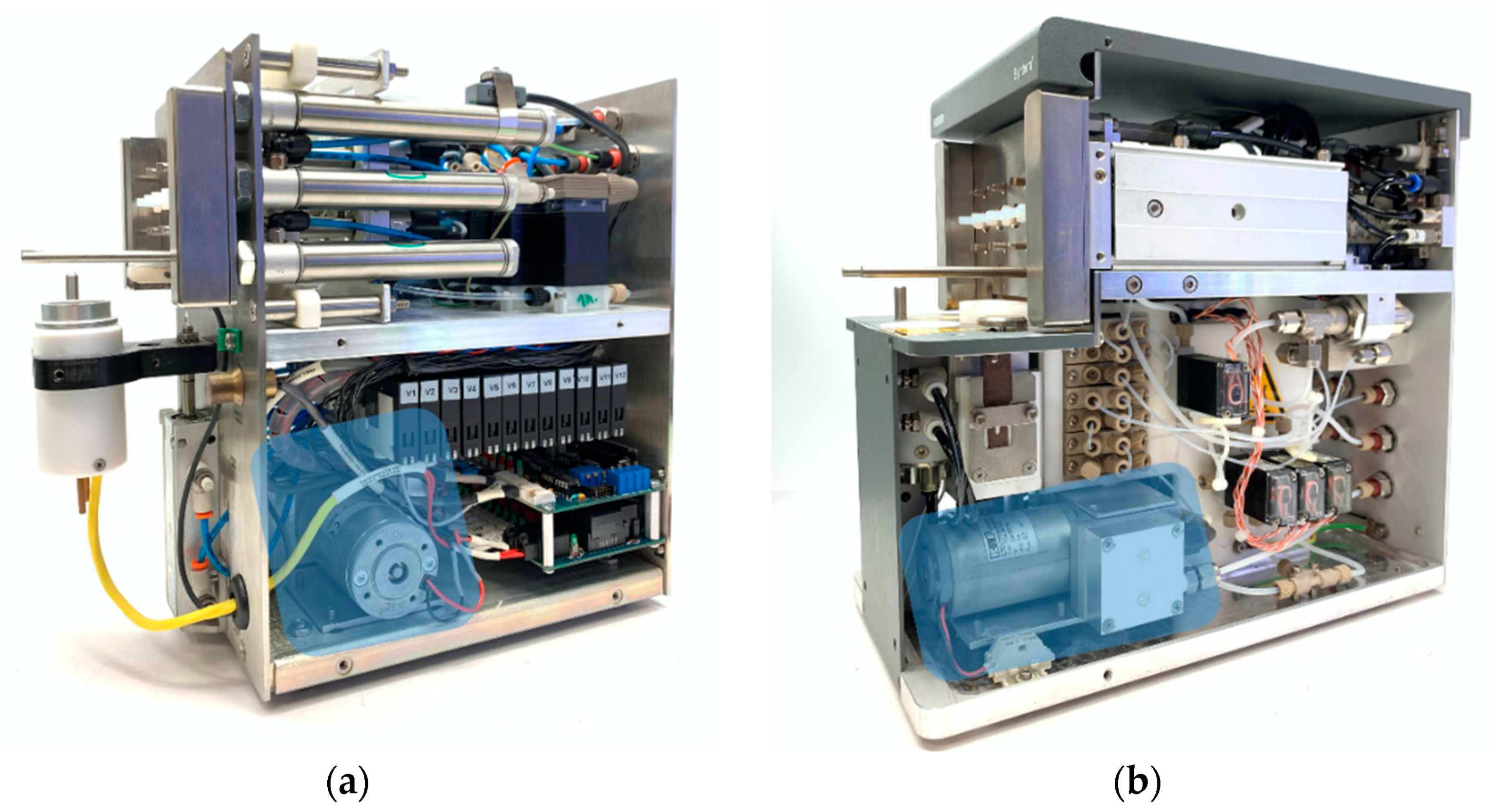
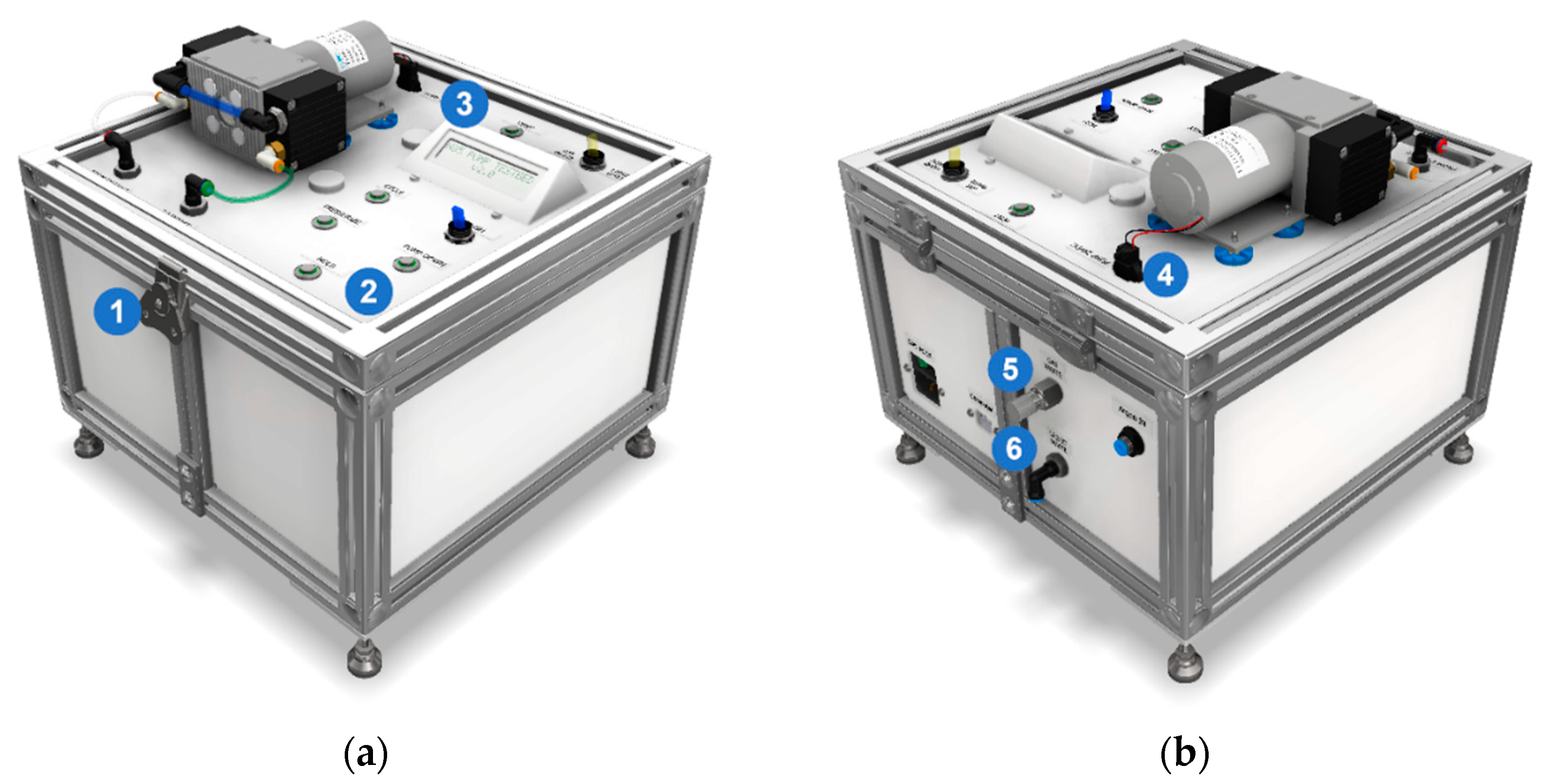
At our institution, we have used IBA Synthera® synthesis modules to produce F-18-labeled radiotracers since 2008. This synthesizer is built to perform chemical reactions using a disposable cassette with a centralized reactor. In simplified terms, the synthesizer comprises a heater, an inert gas supply, pneumatics for the cassette valves, and critically, a vacuum pump for evaporating solvents and transferring reagents. This pump (KNF models N85.3 KNDC or N84.3 ANDC) is essential for achieving a high vacuum to ensure solvent removal, as many reactions are sensitive to water. The location of the pump inside Synthera® V1 and V2 is shown in Figure 1.
The working principle of this type of pump is the deformation of a flexible diaphragm disk inside an internal cavity. A con-rod or other reciprocating mechanical linkage mates the diaphragm to the output shaft of a rotating driving mechanism, typically an electric motor. Each diaphragm head features two directional valves to ensure that fluid is pumped in the correct direction. A pump can be brought back to optimal condition by cleaning the internal surfaces of its heads and replacing the diaphragms, seals, and valves [2] (i.e., rebuilding the pump).
In our use of this equipment, we noticed that over time the pump would lose its ability to pull a high vacuum and fail to pass the radiosynthesis module’s system suitability checks. The causes of these pump failures were typically either vacuum leaks or gradual performance drops caused by the degradation of the internal diaphragms, valves, and seals. Gradual performance losses were caused by a chemical attack by solvents upon the internal rubber components of the pump and by the accumulation of condensation in the fluidic cavities, thus reducing the pumped volume on each stroke [3]. This process is known as cavitation and occurs when the pressure falls below the saturation pressure of the gas, leading to its formation in the suction stage, followed by its growth and eventual implosive collapse during the discharge stage. Cavitation can be reduced by increasing the diameter of the suction line, eliminating flow restriction at the inlet, shortening the suction lines, or switching to a larger pump. These methods, however, are not available in radiotracer synthesis modules with internal vacuum pumps. One method to protect pumps that are available, albeit only for modules with external vacuum pumps, is the addition of a cold trap in the suction line. However, the increase in pumped volume with the addition of a trap has the potential to disturb sensitive chemical reactions.
There are several reasons that prompted the development of an alternative method or apparatus for the assessment of these pumps. If the module had been used recently, the pump might contain residual radioactive chemicals that accumulated during the synthesis. The repair staff would have to wait until it was safe to access the module and remove the pump, potentially causing longer-than-expected equipment downtime. Damage from aggressive solvents can be minimized by preventative methods such as an enhanced purging of the pump after each synthesis (see Supplementary Materials), but the pump had to be replaced or rebuilt eventually. Radiation safety is paramount in radiochemistry laboratories, notably those producing high volumes for distribution [4]. Once the pump was accessible, it was difficult to troubleshoot in the limited space of the lead-shielded workspace, compounded by the possible presence of low levels of residual radioactivity. When a pump was replaced, testing had to be performed within this same environment using the synthesizer. After the pump is cleaned and all damaged parts are replaced, compliance with industry regulations requires that the pump be tested before using it for the production of radiopharmaceuticals [5]. If a pump was rebuilt or a new pump was received, the radiosynthesizer had to be used to validate the pumps, which prevented use for synthesis during this time and risked damaging the module because of the use of metallic tools and leak-finding liquids near the module’s electronics.
We report here on the design, fabrication, and use of a vacuum pump Testbed that provides a safe and accessible way to assess the function of a pump away from the radiosynthesizer. It features a clear user interface and an electronic compound pressure gauge in a spill-proof and portable enclosure.
2. Materials and Methods
2.1. Design Guidelines
A dedicated test device for Synthera® vacuum pumps was conceived upon realizing that we had accumulated eight malfunctioning pumps in need of repair. Validating the repair of each pump using the Synthera® would not only make it unavailable to scientists but also risk causing damage to the synthesis module, ranging from a broken fluidic connector to a current surge with the potential to destroy the module’s electronics.
Following the guidelines of the Pharmaceutical Inspection Co-Operation Scheme (PIC/S) [6]. We elaborated a list of User Requirement Specifications (URS) that the Testbed would have to satisfy:
- Replicates the fluidic pathway of the Synthera® system;
- Wetted surfaces are resistant to ethanol and acetonitrile, the two most abundant solvents to which the pump is exposed during experiments;
- Fluidic components are tight from 0 to 131 kPa absolute, the operational limits of Synthera®;
- Keeps inert gas supply pressure below 131 kPa, the maximum permissible operating pressure limit set by KNF for the pumps in Synthera V1, V2, and Plus;
- A gauge provides the user with a constant reading of the gas pressure at the intake of the pump;
- Components surrounding the pump heads can withstand exposure to a liquid leak-detector solution;
- Compact, portable, and not controlled by a computer;
- Attaching the pump does not require tools;
- Fasteners absorb vibrations from the pump;
- Provides easy access to components to simplify maintenance.
The material cost of building a Testbed was USD 1200. Although no specific limit was set up front, we aimed to keep it below the price of what we considered the most expensive accidental damage: catastrophic electrical damage requiring a new controller assembly for the module, priced at the time at USD 2200.
2.2. Hardware Overview
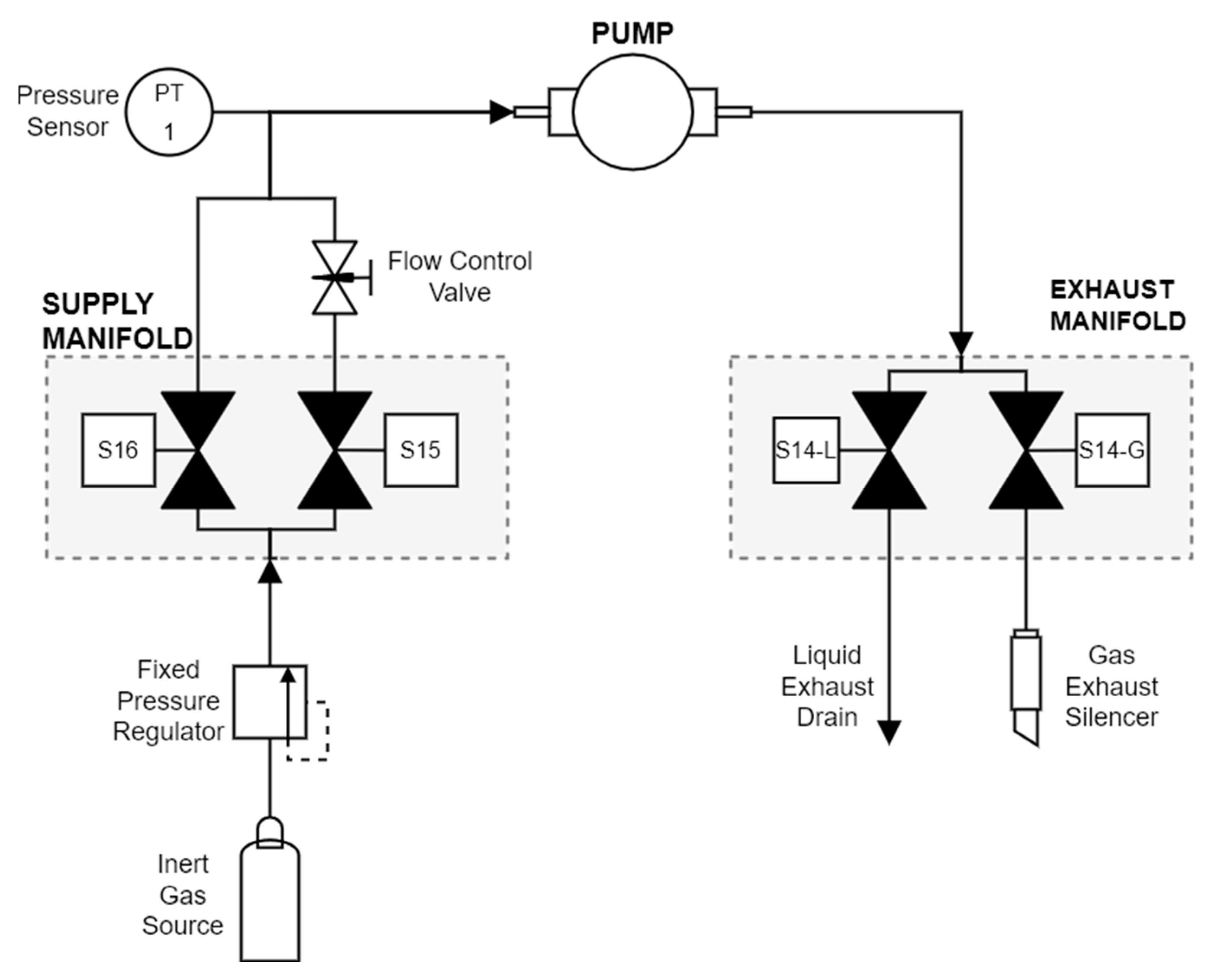
Figure 2 shows a diagram of the Testbed’s fluidic circuit. The intake manifold features two valves, each of which supplies a different flow of inert gas. The flow control after S15 is set low enough for the pump to cope with the flow and is used during the CYCLE step. The flow out of valve S16 is unrestricted and is used in the PRESSURIZE and PUSH steps. Another pair of valves in the exhaust manifold is used to divert gas and liquid waste toward dedicated outlet ports on the rear of the instrument. To ensure that the gas supply does not exceed the operating pressure of the pump, we selected a fixed gas regulator. An electronic pressure sensor provides a constant and accurate reading of the pressure upstream of the pump. An earlier version of the instrument featured an analog dial compound gauge for redundancy, but it was eliminated because an electronic gauge proved to be more accurate and readable.
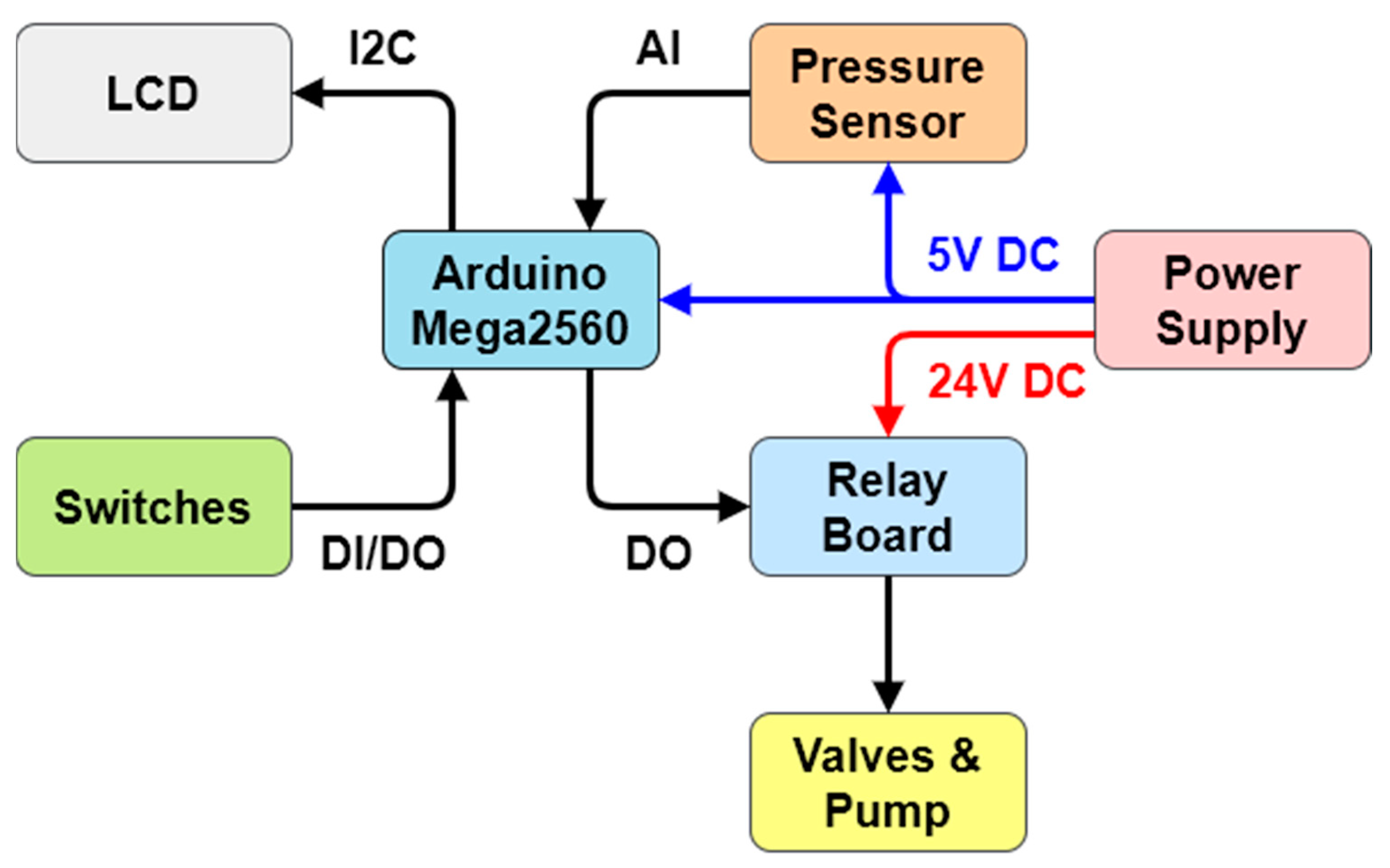
An electronic schematic is shown in Figure 3. The Testbed uses an Arduino MEGA2560 microcontroller. A custom-built shield acts as a connector interface between the Arduino board and the pressure sensor, LCD, buttons, switches, and a relay board to actuate the valves and vacuum pump.
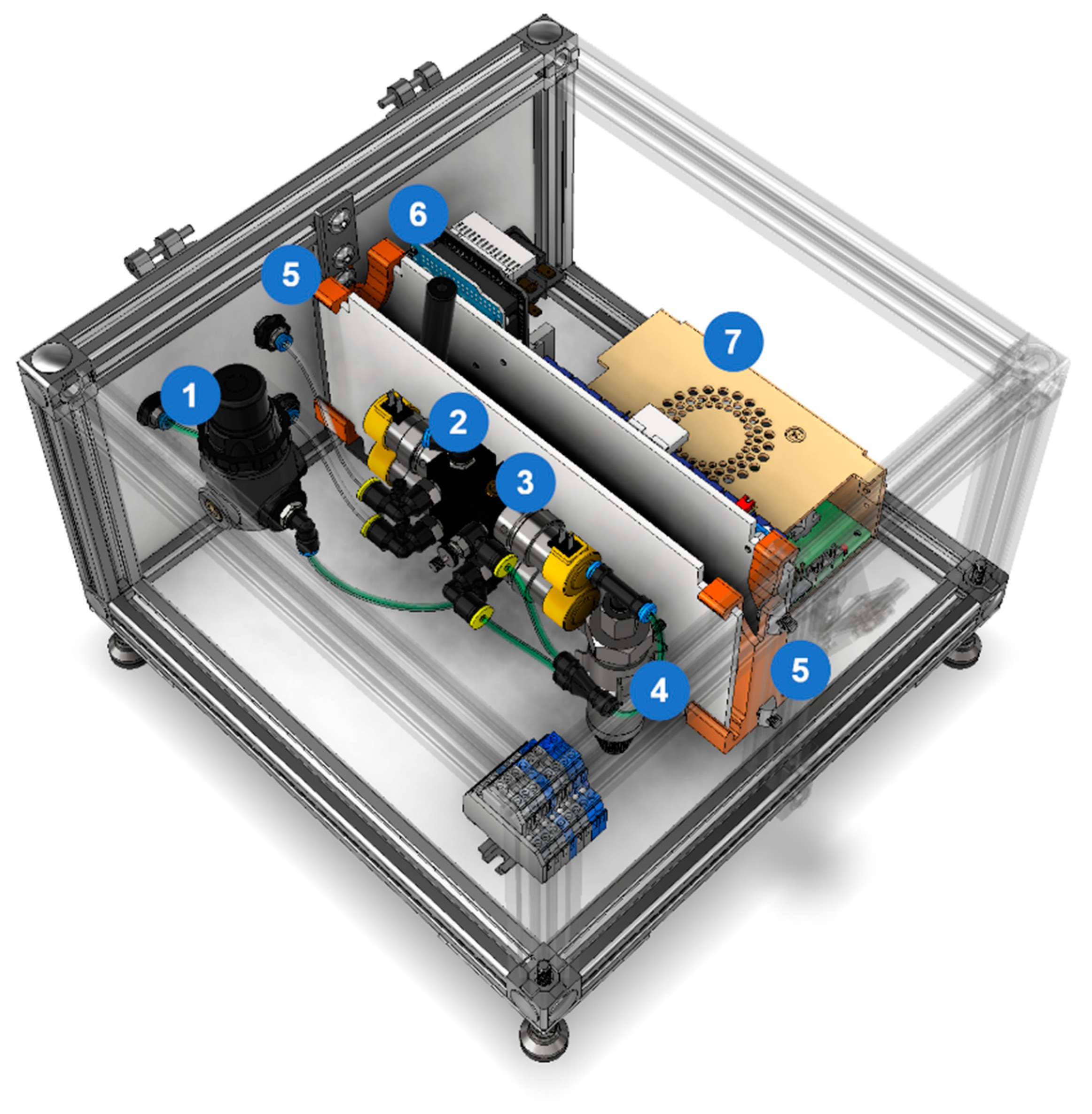
Electronics and valves are mounted to two internal panels. To ease repairs, panels are secured to the enclosure by two 3D-printed mounting clamps, as shown in Figure 4. They are flexible enough to allow tool-free removal of the panels.
A dedicated enclosure was designed in CAD using Autodesk Inventor (Figure 5) and built in-house using polycarbonate panels, t-slotted aluminum extrusion profiles, and connectors. The overall dimensions of the Testbed are 300 mm by 300 mm by 240 mm.
Leak-detecting solutions are frequently used in the troubleshooting of faulty pumps. To prevent spills that could damage its internal components, there is a plastic seal between the polycarbonate panels and the aluminum profiles and seals around the controls.
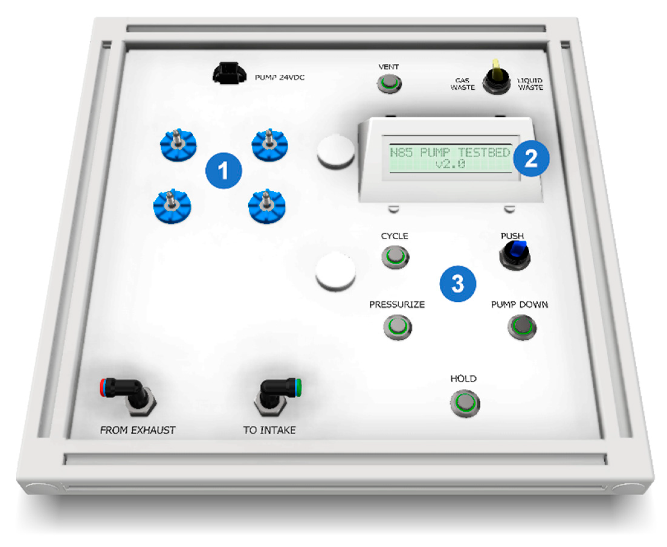
The user interface consists of an alphanumeric LCD screen and illuminated push-buttons and toggle switches (Figure 6). The current mode of operation is shown in the top row of the screen, while the bottom one is reserved for the pressure reading in the system. The display is mounted to a 3D-printed bezel. The design of this component underwent several iterations, resulting in a shape that makes it easy to assemble, protects the surrounding electronics, and presents the display to the user.
A green ring around each of the buttons illuminates while the corresponding mode is selected. The paddles of the toggle switch illuminate when the function they each control is active.
Thumb-screw-head captive panel screws secure the pump to the Testbed. Two washers and a spring on each screw keep them attached to the vibration dampers, eliminating the need for tools and tracking loose fasteners.
Users can enter the liquid waste mode with a dedicated toggle switch. A secondary exhaust valve and outputs route the liquid outside the Testbed, where a collection container is placed. The paddle on the gas/liquid waste selector switch illuminates when the liquid waste mode is enabled to alert the user and prevent accidental spills.
The Testbed User Manual is available in the Supplementary Materials. In addition to usage instructions, it also includes technical specifications, a bill of materials, and detailed wiring schematics.
2.3. Operation Modes
Users select from the five available modes of operation by pressing on dedicated buttons on the top of the Testbed:
- CYCLE: runs the pump and switches the valves automatically to maintain the negative atmospheric pressure inside the pump. This helps clean the pump head internals. A PID (proportional, integral, derivative) algorithm switches the exhaust valve to maintain 65 kPa absolute pressure in the supply line. The operator can manually increase the flow to force the removal of solvents accumulated inside the pump with a flick of the toggle switch;
- PRESSURIZE: increases the internal pressure of the pump. It is used to measure a leak rate or detect leaks;
- VACUUM: runs the pump against a closed inlet. Useful to test the quality of the vacuum;
- HOLD: closes all valves to measure leak rate or detect leaks;
- VENT: the controller opens the exhaust valve to equalize the pressure in the device and the atmosphere. This is recommended before the pump is removed from the instrument.
2.4. Software Interface for Data Logging
Initially, test results were recorded manually in a paper or electronic log. However, after rebuilding and testing several pumps, a data logging application was built using LabVIEW [National InstrumentsTM]. Even though LabVIEW could be used to fully control the Testbed, it was decided to limit it to data logging purposes to shorten development time. Updates to Arduino code.
The source code of the Testbed required little change to transmit the pressure sensor reading to a computer. The following function was added to the void.loop() section to send the reading in kPa whenever it is connected via USB to a computer.
if (Serial.available() == 0) {
Serial.println(pressureKPA);
}
2.4.1. Application Architecture
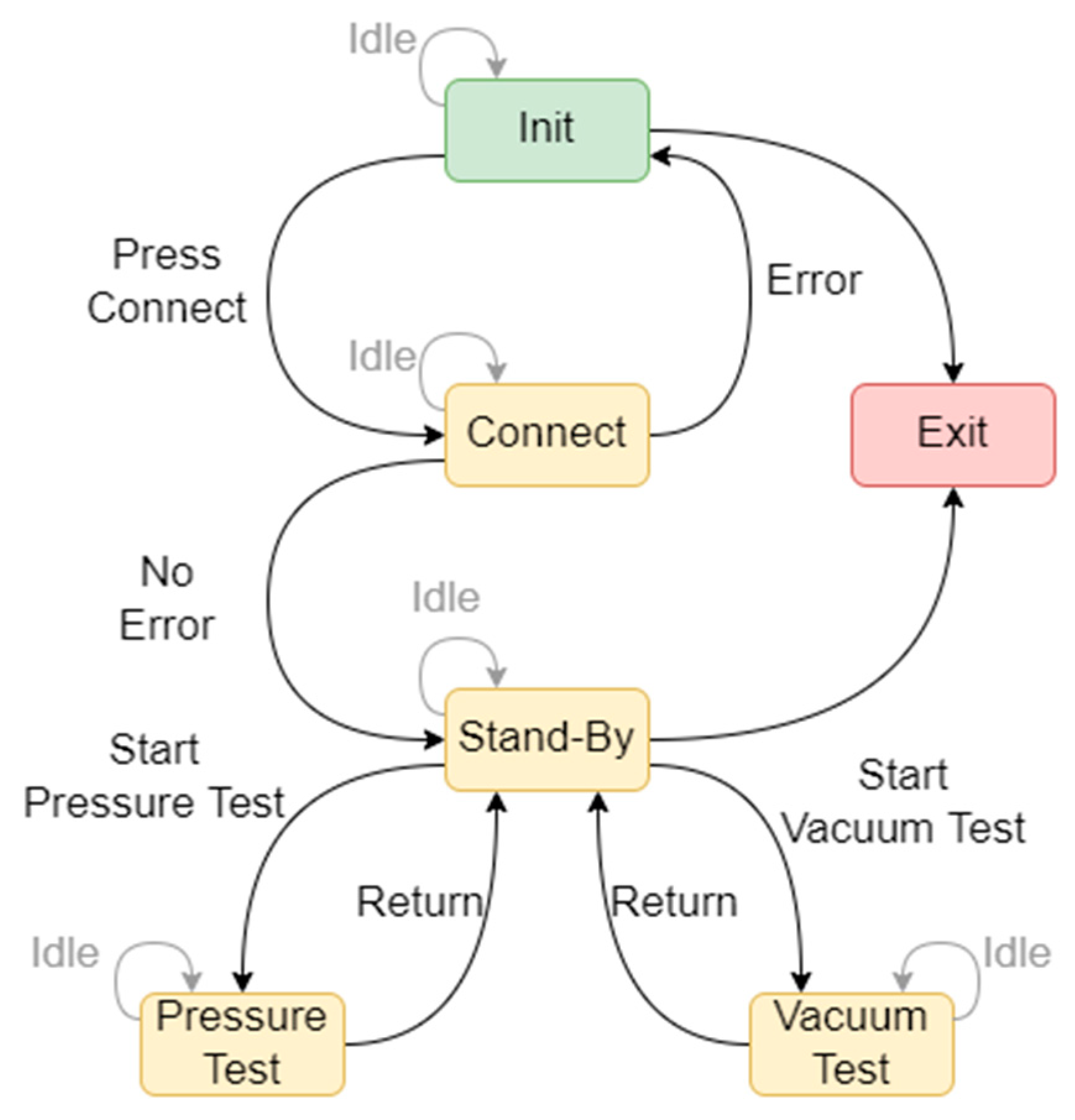
The data logger was built using the National InstrumentsTM State Diagram Editor toolkit for LabVIEW [7]. This toolkit provides significant benefits over the native implementation of the state machine design pattern. It features a graphical window to arrange states and transitions, as shown in Figure 7. The toolkit translates the diagram dynamically to the wiring block diagram with corresponding case structures, enumerated type variables, and case selectors. Without the toolkit, programmers need to create and maintain the type definition controls for each state.
2.4.2. Application Description
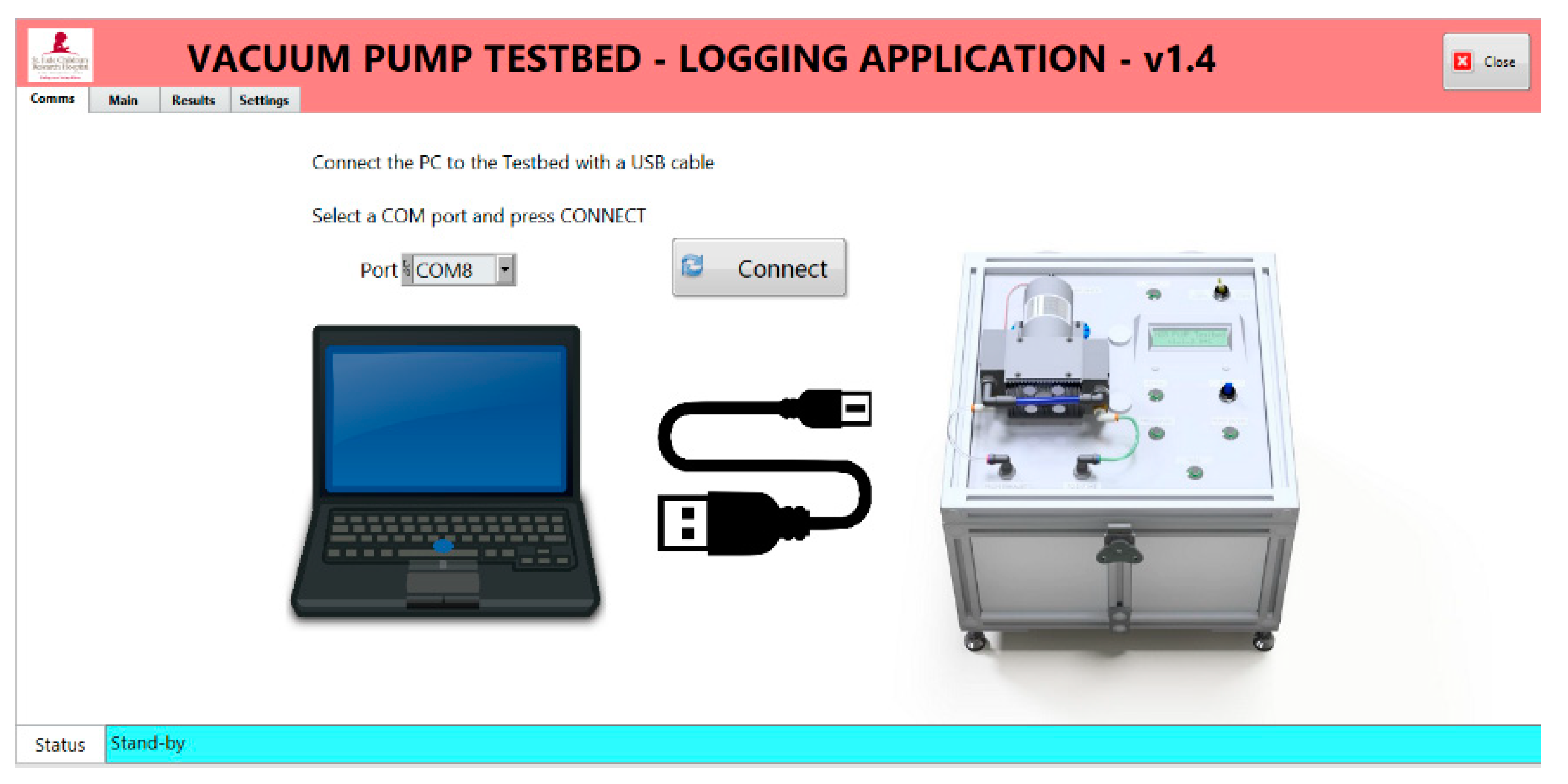
The application is organized into purpose-specific pages accessible through tabs. Upon launching the application, users are prompted by the Comms Tab (Figure 8). to select the USB port connected to the Testbed and press Connect. A successful connection will automatically switch to the Main Tab.
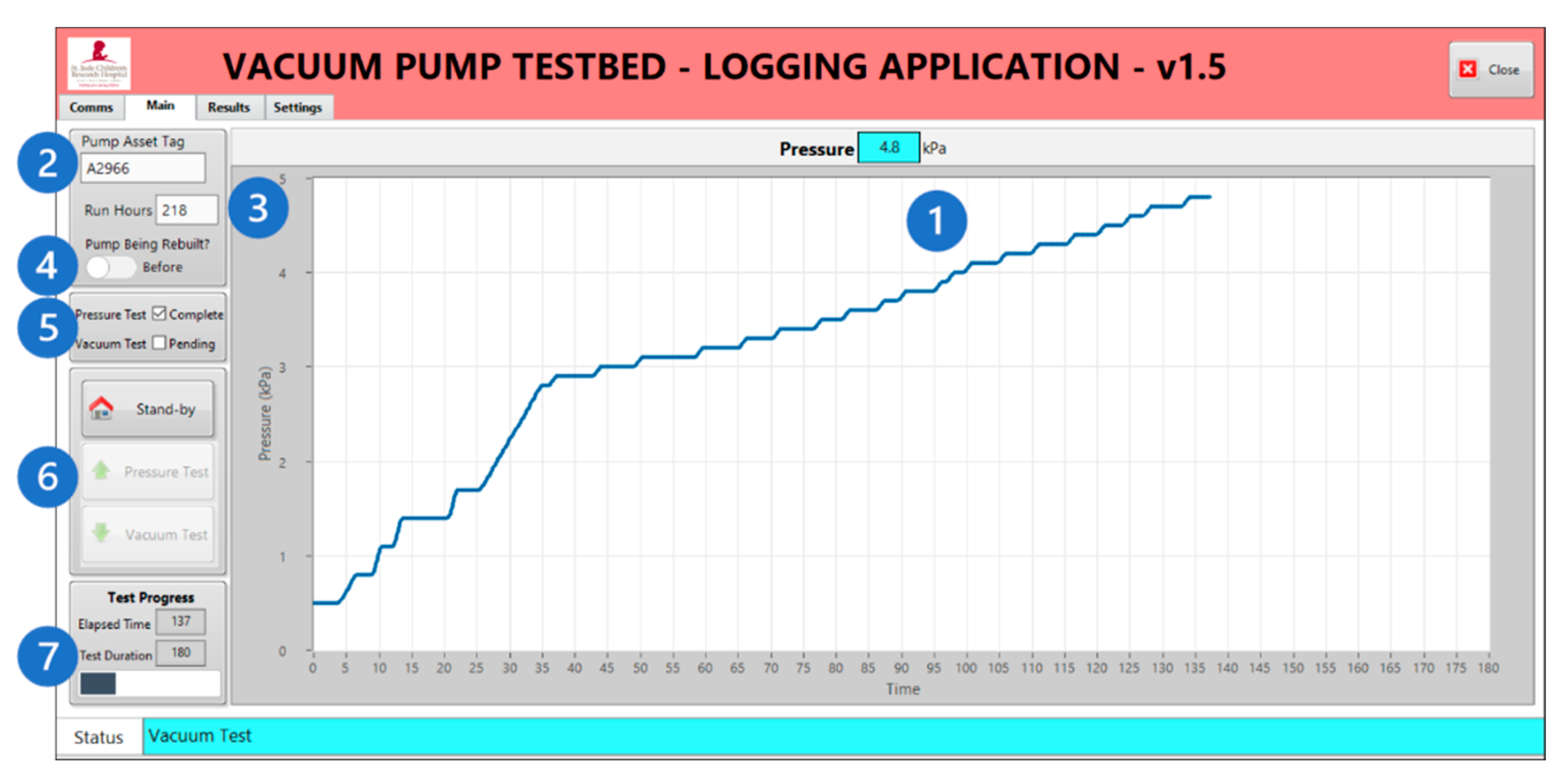
In the Main Tab, users monitor the reading from the pressure sensor, log pump details, and monitor test results (Figure 9).
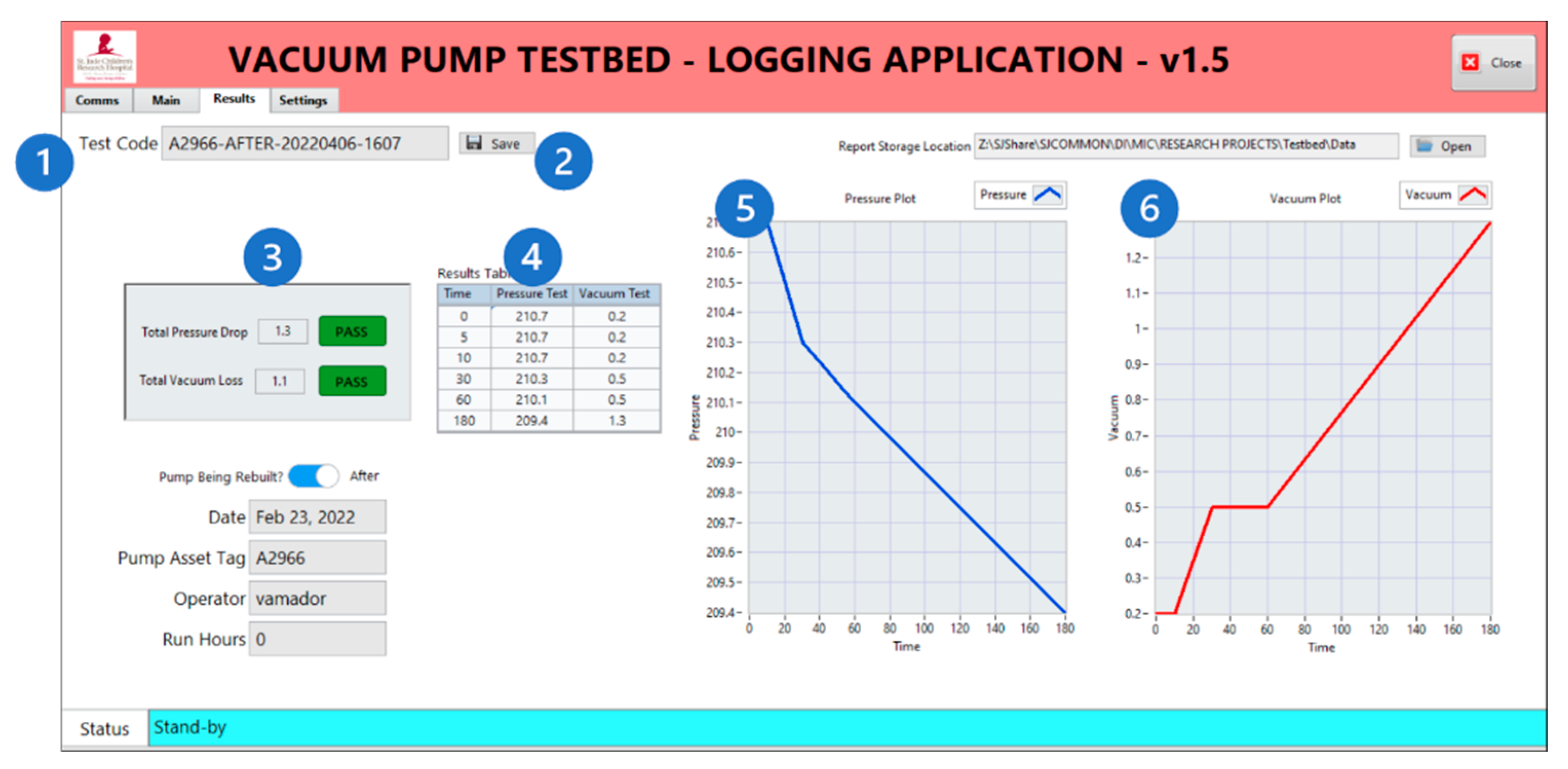
The Results Tab (Figure 10) is a compilation of all logged data and other pertinent information.
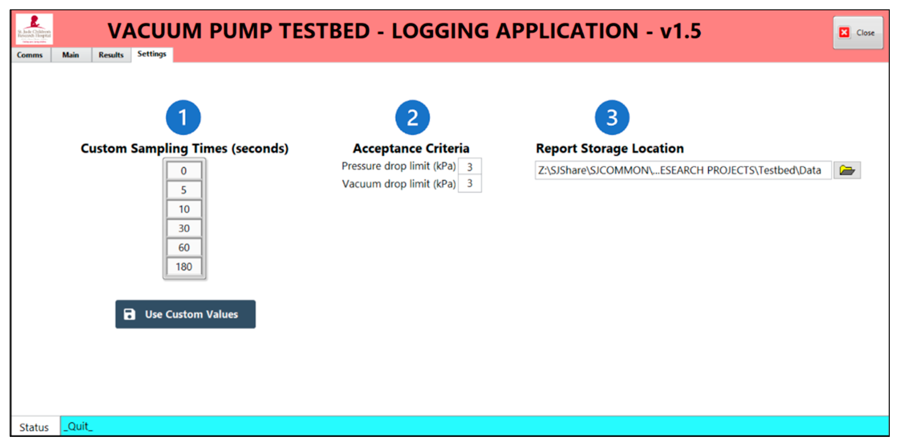
The Settings Tab in Figure 11 presents options to change the sampling times, set acceptance criteria, and designate a report destination folder.
2.5. Extended Compatibility
As is, the Testbed is compatible with all Synthera® synthesis modules from IBA, whether their pump is a KNF N85.3 KNDC or KNF N84.3 ANDC. Moreover, it can also be used for other pumps with minor modifications. Radiosynthesizers manufactured by GE Healthcare (including all FASTlab and some TRACERlab systems), Neptis/Ora, Trasis, and the Multisyn from iPHASE Technologies are also equipped with a KNF N85 pump but are fitted with different electrical and fluidic connections.
The general design of the Testbed should allow use with any diaphragm pump with the appropriate connections to ensure fluidic and electrical tightness and communication. In fact, several radiosynthesizers use a KNF LABOPORT UN820.3 FTP pump and could benefit from a Testbed with minor alterations. These include the ATT Scintomics (GRP), several models from Synthra, Eckert & Ziegler Modular Lab, Elysia-Raytest GAIA systems, and the iPHASE FlexLab. A complete list of compatible radiosynthesizers is available in Appendix A.
Table 1 below summarizes key parameters that support the compatibility between the Testbed and three of the most popular pumps used in radiosynthesizers.
3. Results
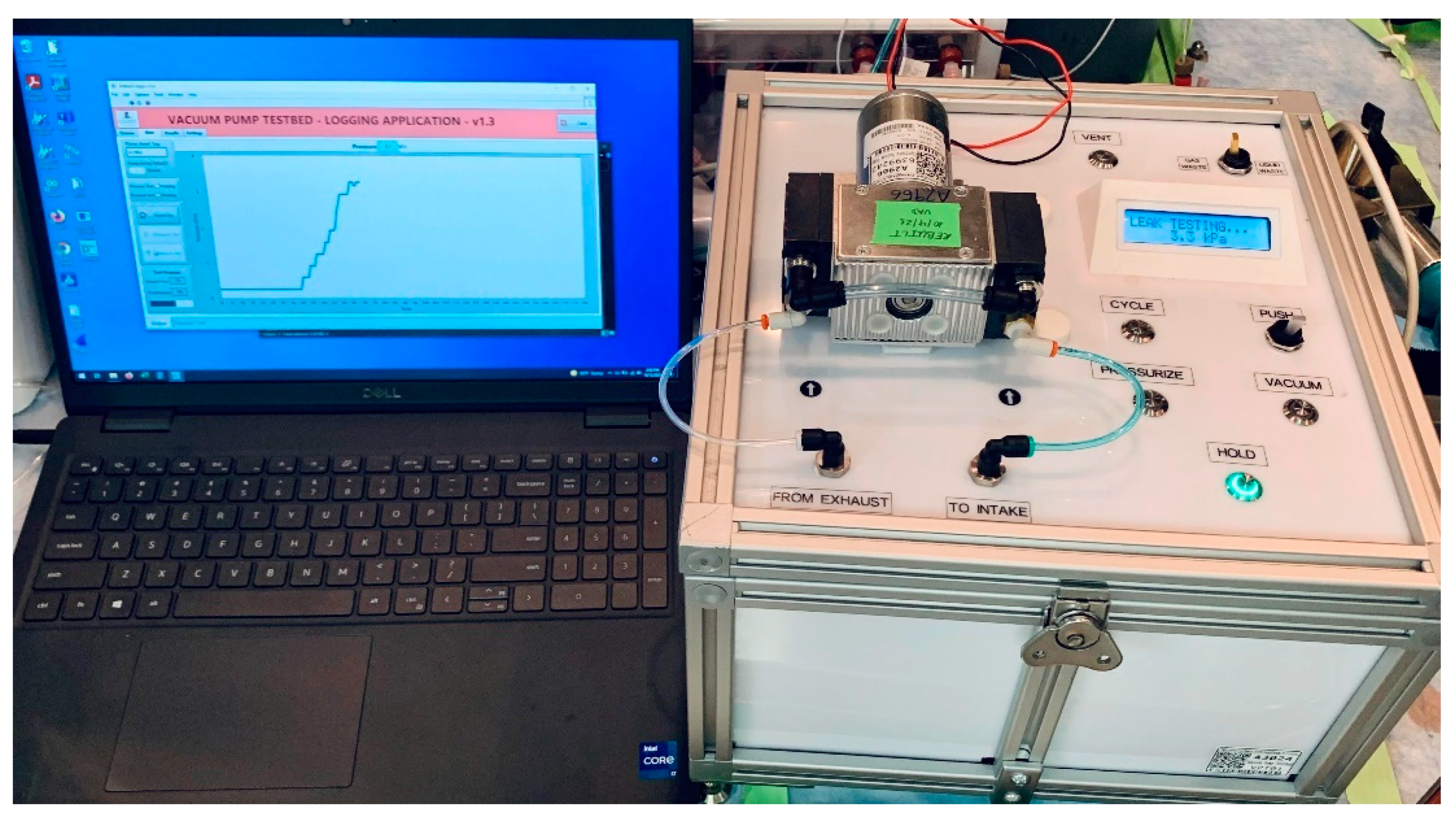
The assembled Testbed was leak tested, and the absolute pressure sensor was checked against a NIST-certified gauge (Figure 12).
3.1. Operation
The Testbed must undergo a system suitability test without a pump present before use. Power it on, connect it to an inert gas source, and use a female coupling push-in connector to join the intake and exhaust lines. Then, select the PRESSURIZE mode and wait for the pressure to stabilize between 205 and 220 kPa. Next, select the HOLD mode to verify the tightness of the fluidic circuit. The recommended acceptance criterion is a pressure drop of 3 kPa after three minutes.
To couple the pump, open the Testbed lid, align the four threaded holes with the captive panel fasteners, and tighten them until the pump’s base touches the blue vibration dampeners. Then, connect the intake and exhaust lines. Finally, plug the pump’s electrical connector into the 24 V DC socket of the Testbed.
If the optional computer application is used, open the executable file and connect the computer to the Testbed male USB-A to male USB-B cable. In the Communications tab of the user interface, select the corresponding COM port number and press CONNECT. If the connection is successful, the application will automatically switch to the Main tab.
Press CYCLE to run inert gas through the pump for at least 5 min. During this time, the Testbed applies a PID algorithm and opens the exhaust valve to maintain 75 kPa upstream of the pump. As solvents are ejected from the pump heads, condensation forms inside the exhaust tubing. To fully remove any liquids from the pump, briefly toggle the PUSH switch to increase the pressure, but not exceed 120 kPa for more than 5 s. If larger drops appear in the exhaust line, allow the pressure to return to 75 kPa and repeat the PUSH toggle until no condensation is visible.
To test the ultimate vacuum of the pump, press VACUUM and verify that the pressure is between 0 and 6 kPa. Once the vacuum stabilizes, press HOLD, and then VACUUM TEST in the Main tab of the logger application to record the results. Similarly, to test the tightness of the pump under pressure, press PRESSURIZE, verify that the pressure is between 200 and 220 kPa, press HOLD, and then PRESSURE TEST to record the results in the application.
If the pump fails the tests, press PRESSURIZE and use your desired leak detection method to survey the pump. If the pump is failing to reach the desired vacuum, it may help to flush the pump with ethanol to remove residual water or organic solvents. To flush the pump, press VENT, toggle the Waste Mode switch to the LIQUID WASTE position, and connect the gas supply line to a syringe barrel containing 5–10 mL of 100% ethanol. Press VACUUM to allow the pump to suction the solvent, then press HOLD and reconnect the gas supply line to the pump’s inlet port. Repeat the testing to reassess the pump’s tightness. If the pump still fails to meet the acceptance criteria, it should be rebuilt. Once the tests are complete, press VENT to equalize the pump and atmospheric pressures, exit the logger application, turn the Testbed off, and disconnect the pump.
The steps above are illustrated in detail in the User Manual included in the Supplementary Materials section.
3.2. Maintenance
Circulate inert gas through the Testbed’s fluidic circuit after exposure to aggressive solvents during cycling and testing. With no pump on the Testbed, verify that the waste selector is in the GAS WASTE position, and use a push-in coupling to join the lines previously connected to the pump. Press CYCLE and let gas flow. Press HOLD and place a container under the liquid waste port on the rear of the Testbed. Move the waste mode selector to the LIQUID WASTE position. Press CYCLE and let the gas flow for 5 min. Disconnect the main inert gas supply line, move the switch in the power entry module to the OFF position, and unplug the Testbed.
Once a year, the Testbed undergoes a series of preventive maintenance tasks:
- Tubing is replaced;
- Fittings and their rubber seals are inspected for wear;
- Valves are disassembled and their internals checked;
- Pressure sensor readings are checked against a NIST-certified gauge. The sensor is not calibrated unless the difference is greater than 10%. (It was not deemed necessary to calibrate yearly because it is not a critical process and the pump will eventually be used on a synthesis module with a calibrated sensor.)
4. Discussions
We believe the Testbed is a valuable tool for the maintenance of laboratory vacuum pumps. Particularly in radiochemistry production facilities, where radiosynthesizer downtime has severe consequences and scheduled downtime is treasured. As presented, the Testbed is compatible with the three most common radiosynthesizer vacuum pumps.
It has not only been used to certify more than a dozen rebuilt pumps but also for screening defective new units prior to installation. On one occasion, it revealed a leak from the sealing compound around the fittings of a brand-new pump that had been in storage for close to a year. This event also uncovered the fittings mismatch discussed in the Supplementary Materials. With a calibrated pressure sensor, the Testbed could also be used during the commissioning and preventive maintenance of radiosynthesizers by the manufacturer’s field service engineers.
Furthermore, it could be used to validate a computational fluid dynamics simulation (CFD) model to investigate the conditions that cause cavitation [8]. Radiosynthesizer and pump manufacturers could use such a model to design fluidic systems and pumps that prevent cavitation, thus extending the service intervals of their equipment.
In conclusion, the return on investment is significant and more than justifies the material and labor costs to develop the Testbed, even before accounting for the accidental damage to the module due to using it as a pump testing platform. For example, the IBA list price at the time of writing of a rebuild kit for the KNF 84.3 ANDC is USD 337.56 and a brand-new pump costs USD 3,424,55. This instrument has become an essential tool in our facility for the repair and maintenance of radiosynthesizer pumps.
Supplementary Materials
The following are available online at https://www.mdpi.com/article/10.3390/instruments7020015/s1, Improvements to fluidic connections, Enhanced pump purge procedure, Reducing Mean Time To Repair (MTTR), Reducing Mean Time To Repair (MTTR), Bill Of Materials, Testbed User Manual (includes usage instructions, technical specifications, bill of materials, and detailed wiring schematics), Instrument and Operation Qualification Protocol.
Author Contributions
Conceptualization, V.A.D.; methodology, V.A.D.; software, V.A.D.; validation, V.A.D.; formal analysis, V.A.D.; investigation, V.A.D.; resources, V.A.D., S.E.S. and A.L.V.; data curation, V.A.D.; writing—original draft preparation, V.A.D. and A.L.V.; writing—review and editing, A.L.V. and S.E.S.; visualization, V.A.D. and A.L.V.; supervision, A.L.V. and S.E.S.; project administration, V.A.D.; funding acquisition, A.L.V. and S.E.S. All authors have read and agreed to the published version of the manuscript.
Funding
This project was funded by ALSAC-St. Jude Children’s Research Hospital.
Data Availability Statement
Pump test reports are available upon request from the corresponding author.
Acknowledgments
We thank Guillaume Villeret, Technical Director with Ora/Neptis for detailing the vacuum pump model used in the Neptis radiosynthesizers.
Conflicts of Interest
The authors declare no conflict of interest.
Appendix A

Table A1.
Modules with readily compatible pumps.
| Manufacturer | Radiosynthesizer Model |
|---|---|
| Ion Beam Applications (IBA) | Synthera |
| Synthera V2 | |
| Synthera Plus | |
| General Electric Healthcare | FASTlab 1 |
| FASTlab 2 1 | |
| TRACERlab FX2 C | |
| TRACERlab FX2 MeI | |
| TRACERlab FX C (pro) | |
| TRACERLAB MX | |
| TRACERLAB MX FDG | |
| iPHASE Technologies | MultiSyn |
| Neptis/Ora | Neptis Perform |
| Neptis RS | |
| Neptis DB | |
| Neptis LC | |
| Neptis xSeed | |
| Neptis SP | |
| Sofie Biosciences | Elixys Flex/Chem 2 |
| Trasis | AllInOne |
Table A2.
Synthesis modules featuring KNF LABOPORT 820.3 FTP pumps.
| Manufacturer | Radiosynthesizer Model |
|---|---|
| ATT Scintomics | GRP |
| Hot Box III | |
| Synthra | Gpextent |
| HCNplus | |
| [C-11]Acetate | |
| RNplus | |
| RNplus Research | |
| FDGtwo | |
| Multitracer | |
| F-Dopa | |
| Peptide | |
| Ammonia | |
| Iodine | |
| Eckert & Ziegler | Modular-Lab PharmTracer |
| Modular-Lab Standard | |
| Elysia-Raytest | GAIA |
| GAIA V2 | |
| General Electric Healthcare | TRACERlab FX2 C |
| TRACERlab FX2 E | |
| TRACERlab FX2 N | |
| TRACERlab FX-FDG | |
| iPHASE Technologies | FlexLab |
References
- Covens, P.; Berus, D.; Vanhavere, F.; Caveliers, V. The introduction of automated dispensing and injection during PET procedures: A step in the optimisation of extremity doses and whole-body doses of nuclear medicine staff. Radiat. Prot. Dosim. 2010, 140, 250–258. [Google Scholar] [CrossRef] [PubMed]
- KNF Neuberger GmbH. Diaphragm Vacuum Pumps N85 and N86. Operating and Installation Instructions. 2016, p. 40. Available online: https://knf.com/fileadmin/user_upload/BA121258-121528_N85_86-en010_0120.pdf (accessed on 4 May 2022).
- Pfeiffer Vacuum GmbH. Vacuum Technology and Know How. 2013, p. 58. Available online: https://www.pfeiffer-vacuum.com/en/know-how/container!download.action?referer=1456&download=/filepool/file/literature/vacuum-technology-book-ii-part-2.pdf (accessed on 3 April 2023).
- Eberl, S.; Eriksson, T.; Svedberg, O.; Norling, J.; Henderson, D.; Lam, P.; Fulham, M. High beam current operation of a PETtraceTM cyclotron for 18F−Production. Appl. Radiat. Isot. 2012, 70, 922–930. [Google Scholar] [CrossRef] [PubMed]
- Current Good Manufacturing Practice for Positron Emission Tomography Drugs, 21 C.F.R. §212.60. Available online: https://www.accessdata.fda.gov/scripts/cdrh/cfdocs/cfcfr/CFRSearch.cfm?fr=212.60 (accessed on 3 April 2023).
- Pharmaceutical Inspection Co-operation Scheme. PI 011-3—PIC/S Guidance—Good Practices for Computerised “ Gxp ” Environments. PIC/S Secretariat, Editor. PIC/S. 2007. Available online: https://picscheme.org/docview/3444 (accessed on 4 June 2022).
- LabVIEW State Diagram Toolkit Download—NI. Available online: https://www.ni.com/en-us/support/downloads/tools-network/download.labview-state-diagram-toolkit.html#374363 (accessed on 23 February 2022).
- Fang, Y.; Zhang, J.; Xu, B.; Mao, Z.; Li, C.; Huang, C.; Lyu, F.; Guo, Z. Raising the Speed Limit of Axial Piston Pumps by Optimizing the Suction Duct. J. Mech. Eng. 2021, 34, 105. [Google Scholar] [CrossRef]
- GE Healthcare. DOC0839069—FASTlab Service Manual, 3rd ed. 2019. Available online: https://customer-doc.cloud.gehealthcare.com/copyDoc/DOC0839069/3 (accessed on 21 January 2022).
- GE Healthcare. DOC1615837—FASTlab 2 Synthesizer Service Manual, 11th ed. 2021. Available online: https://customer-doc.cloud.gehealthcare.com/copyDoc/DOC1615837/11 (accessed on 21 January 2022).
Figure 1.
Vacuum pump location inside IBA Synthera radiosynthesizers: (a) Synthera V1 and (b) Synthera V2. Newer Synthera units include a slightly different pump, a KNF N84.3 ANDC. Their aluminum heads and PTFE-coated diaphragms make them more resilient, but not immune, to solvent attack.
Figure 1.
Vacuum pump location inside IBA Synthera radiosynthesizers: (a) Synthera V1 and (b) Synthera V2. Newer Synthera units include a slightly different pump, a KNF N84.3 ANDC. Their aluminum heads and PTFE-coated diaphragms make them more resilient, but not immune, to solvent attack.

Figure 2.
Fluidic diagram of the Testbed.

Figure 3.
Electronic circuit diagram.

Figure 4.
Interior view of the Testbed. The custom-made clamps are highlighted in orange. (1) fixed output pressure regulator; (2) intake manifold; (3) exhaust manifold; (4) electronic pressure/vacuum gauge; (5) custom mounting clamps; (6) microcontroller; (7) power supply.
Figure 4.
Interior view of the Testbed. The custom-made clamps are highlighted in orange. (1) fixed output pressure regulator; (2) intake manifold; (3) exhaust manifold; (4) electronic pressure/vacuum gauge; (5) custom mounting clamps; (6) microcontroller; (7) power supply.

Figure 5.
Computer model of the Testbed. (a) The front quarter view shows (1) the quick-turn draw latch, (2) the control panel, and (3) the custom LCD bezel. (b) The rear quarter view shows (4) the power plug for the pump, (5) the muffler for the gas exhaust, and (6) an elbow fitting pointing downwards to drain exhaust liquids.

Figure 6.
Lid subassembly featuring (1) captive panel screws and rubber vibration dampening grommets; (2) an LCD mounted on the bezel; and (3) illuminated controls.
Figure 6.
Lid subassembly featuring (1) captive panel screws and rubber vibration dampening grommets; (2) an LCD mounted on the bezel; and (3) illuminated controls.

Figure 7.
State Machine Diagram of the data-logging application generated with the National InstrumentsTM State Diagram Editor toolkit for LabVIEW. Green represents the initial state, yellow is for the intermediate, and red is for the terminal state. Arrows represent state transitions.
Figure 7.
State Machine Diagram of the data-logging application generated with the National InstrumentsTM State Diagram Editor toolkit for LabVIEW. Green represents the initial state, yellow is for the intermediate, and red is for the terminal state. Arrows represent state transitions.

Figure 8.
Communications Tab.

Figure 9.
Main Table: (1) Chart Panel: shows the current pressure value and a historical graph; (2) Pump Asset Tag: the user enters the asset tag value of the pump being tested; (3) Run Hours: the user enters a value from the pump’s hour meter (the installation of an hour meter is detailed in the Supplementary Materials); (4) Pump Being Rebuilt: the user designates if the test takes place before or after the pump has been rebuilt; (5) Test Status Panel: automatically checks when the pressure and vacuum tests are complete; (6) Mode Panel: Stand-by: no data are being saved in this mode; Pressure Test: saves readings to the pressurization section of the report; Vacuum Test: saves readings to the vacuum tightness section of the report; (7) Test Progress Panel: Elapsed Time: shows time passed since the start of the pressure or vacuum test; Test Duration: shows the duration of the pressure or vacuum test.

Figure 10.
Results Table (1) Test Code: a concatenated string automatically generated using the pump asset tag code, rebuild status, date, and time the test was completed; (2) Save button: takes a screenshot of the Results tab and saves it to the chosen destination folder as a JPEG file with the Test Code name; (3) Pass/Fail Panel: reports pressure drop and vacuum loss and compares with acceptance criteria; (4) Results Table: readings at six-time points configurable in the Settings tab; (5) Pressure Plot: plots the results of the pressurization test; (6) Vacuum Plot: plots the results of the vacuum tightness test.

Figure 11.
The Settings Table allows users to check or change selected test parameters. Values are reset to their defaults the next time the application is launched. (1) Custom Sampling Times; (2) Acceptance Criteria; (3) Report Storage Location.
Figure 11.
The Settings Table allows users to check or change selected test parameters. Values are reset to their defaults the next time the application is launched. (1) Custom Sampling Times; (2) Acceptance Criteria; (3) Report Storage Location.

Figure 12.
Testbed and LabVIEW application conducting a vacuum tightness test.

Table 1.
Specifications of the three most popular radiosynthesizer vacuum pumps against the capabilities of the Testbed.
Table 1.
Specifications of the three most popular radiosynthesizer vacuum pumps against the capabilities of the Testbed.
| Pump Model | N85.3 KNDC | N84.3 ANDC | N820.3FTP | Testbed |
|---|---|---|---|---|
| Electrical Data | ||||
| Voltage (V) | 24 | 24 | 115 V/60 Hz or 220 V/50 Hz | 115 V/60 Hz |
| Power (W) | 16.8 | 18 | 130 | Available: 240 |
| Performance Data | ||||
| Max. operating pressure (kPa abs) | 131 | 131 | 201 | 824 |
| Ultimate Vacuum (kPa abs) | 2.5 | 0.7 | 0.8 | 0.3 |
| Flow at atm. Pressure (L/min) | 5 | 5 | 20 | 6 |
Disclaimer/Publisher’s Note: The statements, opinions and data contained in all publications are solely those of the individual author(s) and contributor(s) and not of MDPI and/or the editor(s). MDPI and/or the editor(s) disclaim responsibility for any injury to people or property resulting from any ideas, methods, instructions or products referred to in the content. |
© 2023 by the authors. Licensee MDPI, Basel, Switzerland. This article is an open access article distributed under the terms and conditions of the Creative Commons Attribution (CC BY) license (https://creativecommons.org/licenses/by/4.0/).
Share and Cite
MDPI and ACS Style
Amador Diaz, V.; Snyder, S.E.; Vavere, A.L. Design and Manufacture of a Test Device for Radiosynthesizer Vacuum Pumps. Instruments 2023, 7, 15. https://doi.org/10.3390/instruments7020015
AMA Style
Amador Diaz V, Snyder SE, Vavere AL. Design and Manufacture of a Test Device for Radiosynthesizer Vacuum Pumps. Instruments. 2023; 7(2):15. https://doi.org/10.3390/instruments7020015
Chicago/Turabian StyleAmador Diaz, Victor, Scott E. Snyder, and Amy L. Vavere. 2023. "Design and Manufacture of a Test Device for Radiosynthesizer Vacuum Pumps" Instruments 7, no. 2: 15. https://doi.org/10.3390/instruments7020015