1. Introduction
Muon radiography is developing rapidly and it is increasingly in demand in several new fields. The capability to identify underground cavities, while preserving them from any invasive intervention, makes muography of great interest for arcaeology [
1,
2], mining, and urban applications. Considering the topology of a certain structure under study, and assuming that it is entirely composed of rock, muons spot out the possible presence of cavities, being less absorbed than expected. Traversing a cavity, muons pass through a less dense region, decreasing the number of interactions they undergo. This effect manifests in a local excess of particles, coming from directions within a certain range of angles. This excess is enhanced in a muographic image, where the observed flux is represented relative to the expectations.
The detection of cavities inside heritage buildings can, for instance, prevent possible damages, or can led to the discovery of unknown cavities, as in the case of pyramids [
3]. Furthermore, muon radiography can help in urban security surveys and can be also used as an online monitor of the target of the muographic inspection to discover possible modification, when the thickness range is under ∼100 m.
One of the primary difficulties of applying muon radiography for this kind of applications is that often the target is underground and, since the experimental set-up must be installed under the region to be investigated, a suitable underground location to install the apparatus is needed and also must be easily accessible by people. In many cases this necessity becomes a strong limitation with standard detectors. We developed a new compact borehole detector to deal with this issue. Furthermore, the usage of boreholes allows us to investigate deeper in the underground, up to the kilometer scale, where, for instance, gas reservoirs, salt domes, geological anomalies can be found.
The novel detector has a cylindrical geometry, and its size can fit standard realizable drilled wells. In the following, the detector is described in exact detail, and the results of the test phase and preliminary underground applications are presented.
2. The Detector
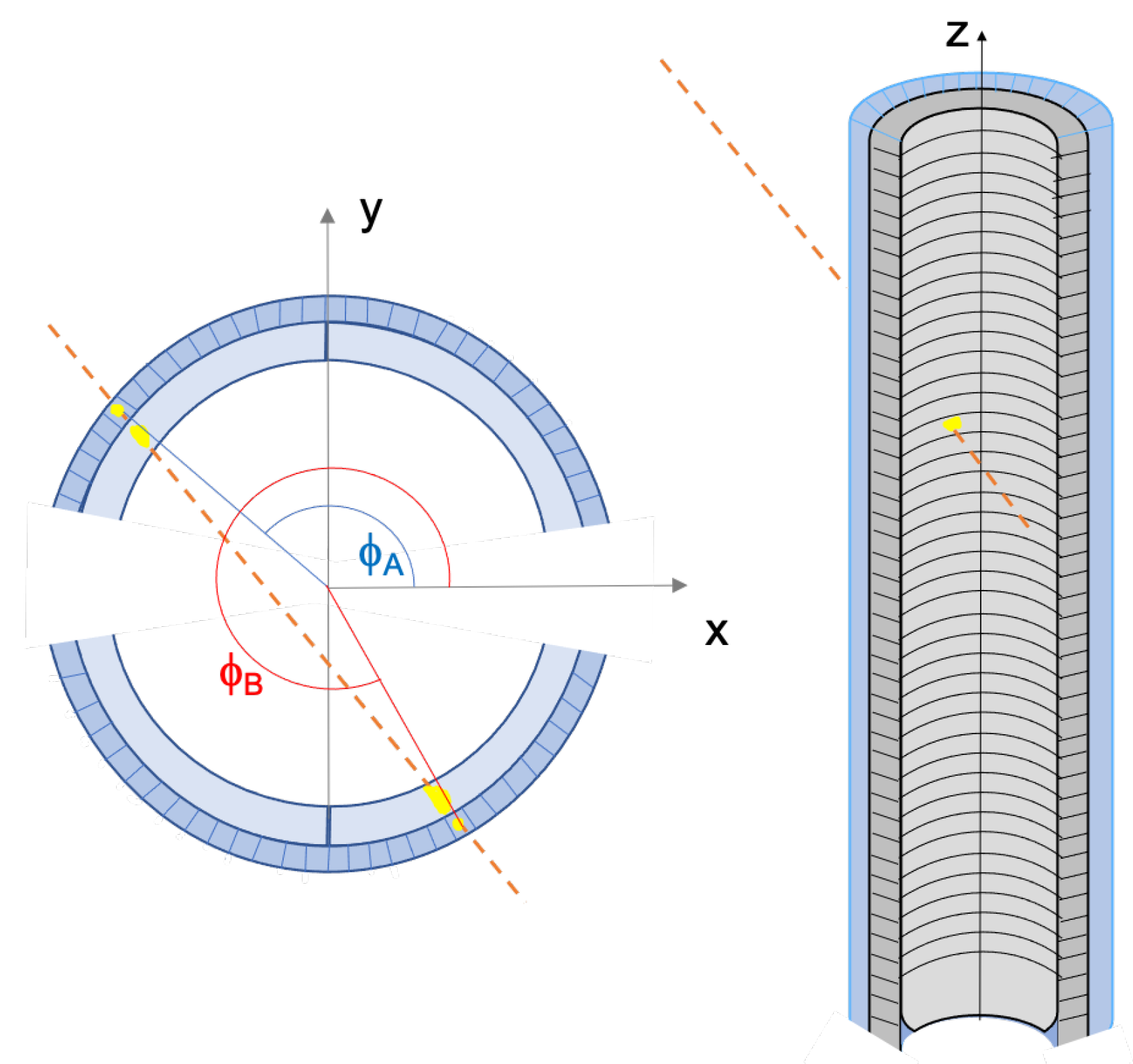
The new borehole detector has a cylindrical sensitive surface, realized through the use of scintillators in the shape of arcs. This geometry allows the acceptance to be maximized with respect to the compact size. It is 1 m long and has a 24 cm diameter. The sensitive elements are scintillators in the shape of arcs covered by a layer of scintillator bars parallel to the cylinder axis.
The cylindrical detector consists of 64 inner layers of arc-shaped scintillators and one outer layer of 1 m bars arranged axially. It is divided in two semi-cylindrical sections, each covering 166 horizontal degrees. Between the two sections, two 14 degrees empty gaps are interposed, necessary to leave space for devices reading arcs. These gaps are the major inefficiency source of the detector, even though they don’t determine any completely dead zone, but lower the efficiency of the corresponding angular regions. Thus, the detector is oriented in the way that these gaps correspond to regions not included in the desired field of view. Considering a system of cylindrical coordinates the bars are meant to measure the hit angle
, while the arcs provide the
z coordinate, as shown in
Figure 1. The bars have a rectangular section of 8.5 mm × 6.5 mm. Arcs have internal and external radius of 83 and 93 mm respectively and the height is 15 mm. Each semi-cylinder is composed of 64 layers of arc pairs, for a total of 128 arcs covered by 32 bars. The whole detector thus consists of 256 arcs and 64 bars optically coupled with Silicon Photomutipliers (SiPMs). Since bars are read from both sides, the apparatus includes a total of 384 photosensors. If positioned vertically, the detector provides an average angular resolutions of the muon direction of about 0.7
and 3
in azimuth and zenith respectively.
Scintillators are hosted in containers realized in Acrylonitrile Butadiene Styrene (ABS) with a 3D printer; each container consists of 16 layers of holes to insert arcs and 32 vertical holes to insert bars. Each semicylinder is obtained by stacking 4 containers.
The SiPMs used are S13360-3050PE by Hamamatsu and have a sensitive area of 3 × 3 mm
The sensors are read by a dedicated Front-End and DAQ electronics, based on the experience with previous muon radiography projects [
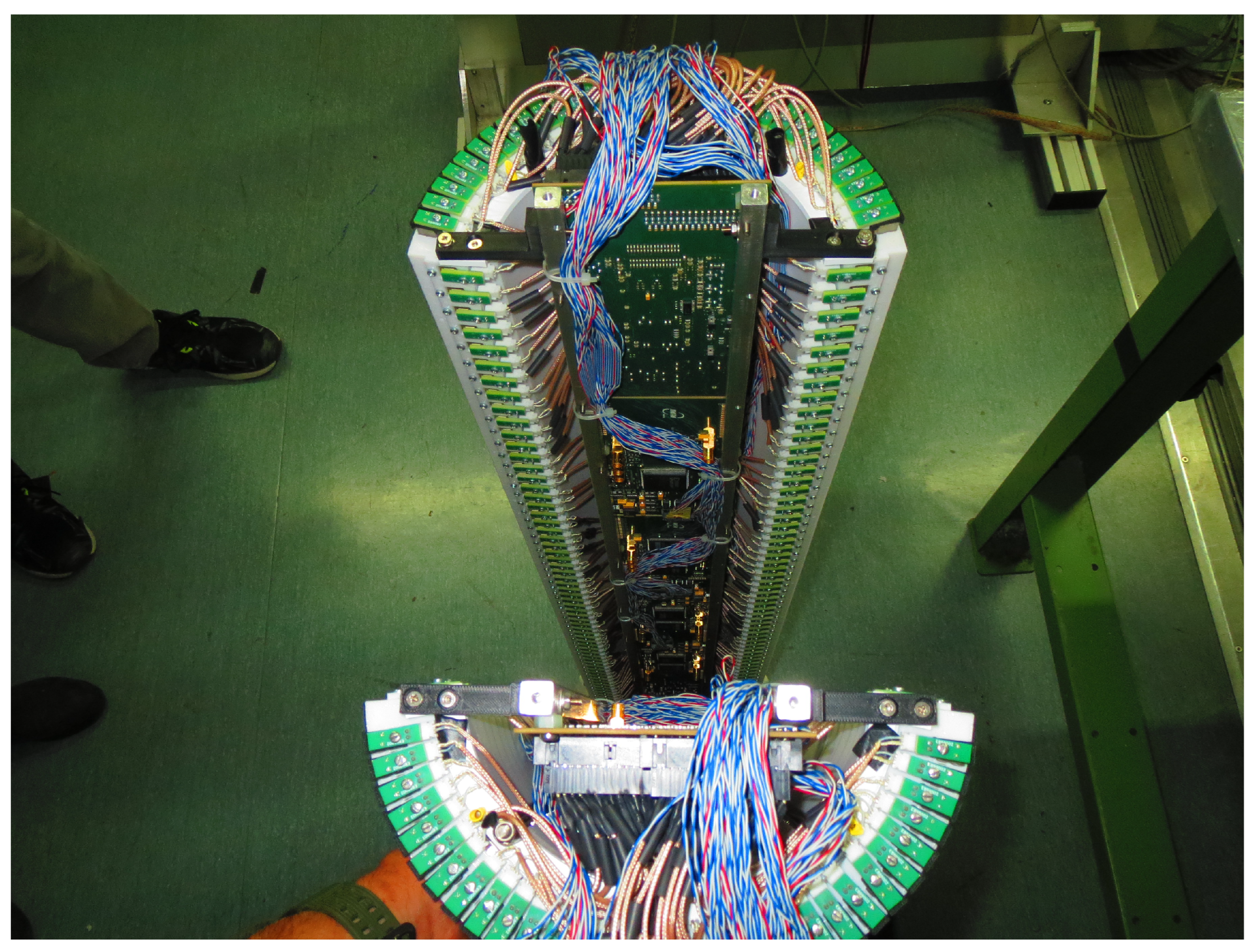
4]. The system has been developed in response of the peculiar necessities of muon radiography experiments, paying particular attention to the compactness and power consumption. Indeed, FEE boards must be compact enough to be housed in the small space inside the cylinder (
Figure 2). The FEE electronics is very low power consuming, about 30 W for the whole detector, since many muon radiography applications need the detector to be installed in places where direct electricity is not available and therefore it is necessary to use alternative sources, such as photovoltaic or wind power. It is also important to avoid producing too much heat, since heat exchange with the outside is limited due to the watertight shell protecting the detector. Each slave board is based on the EASIROC ASIC [
5], an easy and versatile readout device specifically developed for SiPMs. A total of 12 boards are embedded in the cylinder body, each connected to 32 SiPMs. A Digital to Analogical Converter (DAC) assigns a programmable voltage threshold to the boards; if this threshold is exceeded by one of the 32 SiPMs, the board produces a fast logic signal (OR32). The produced OR32 are sent to a MASTER board which enables the data acquisition if the programmed trigger logic is satisfied. The MASTER is provided with an FPGA for the data transfer with the FEE and a Raspberry-Pi computer for communicating with the internet. The detector is also equipped with an Arduino to monitor temperature and humidity, measured by four sensors (HDC1050 by Texas Instruments) inside the detector housing.
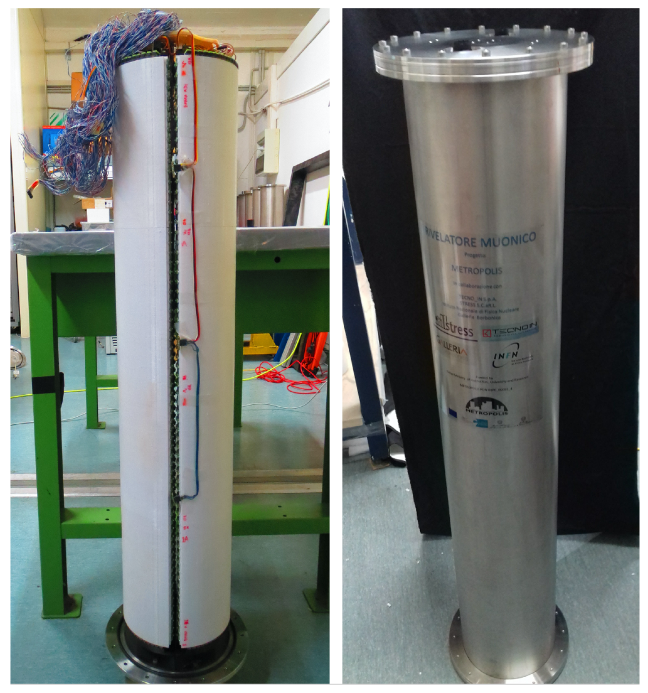
The detector is finally inserted in a stainless steel watertight shell and its final dimensions are 25 cm diameter and 1.2 m lenght. The final assembly of the detector is shown in
Figure 3.
DAQ System
When a muon passes through the detector, the intercepted scintillator elements react by producing light that is translated through the chain SiPM-electronics in over-threshold signals. Signals overcoming the threshold are sent to the Master board, which enable the Data AQuisition (DAQ) after checking if the trigger logic is satisfied.
A FEE board provides a Local Trigger (LT) when at least one of the 32 channels has a signal above the threshold. Threshold values are set in order to avoid dark-noise triggering the boards. The optimal working point of the detector is thus set according to the requirement of negligible dark noise contamination. Since dark noise depends on the temperature, the detector is provided with a system that automatically changes the operating voltage when working conditions change, compensating for fluctuations in the SiPM breakdown voltage.
When a Global Trigger (GT) occurs, the DAQ is activated. The GT logic is programmable; for the present applications the set-up trigger logic can be described as follows. Considering A11, A12, A21 and A22 the OR of the 4 stacks of arcs, and B1, B2 the two groups of bars of each semi cylinder, the GT requires:
meaning that at least 1 semi-cylinder must be fired, involving at least one bar and one arc.
3. Free-Sky Data-Taking
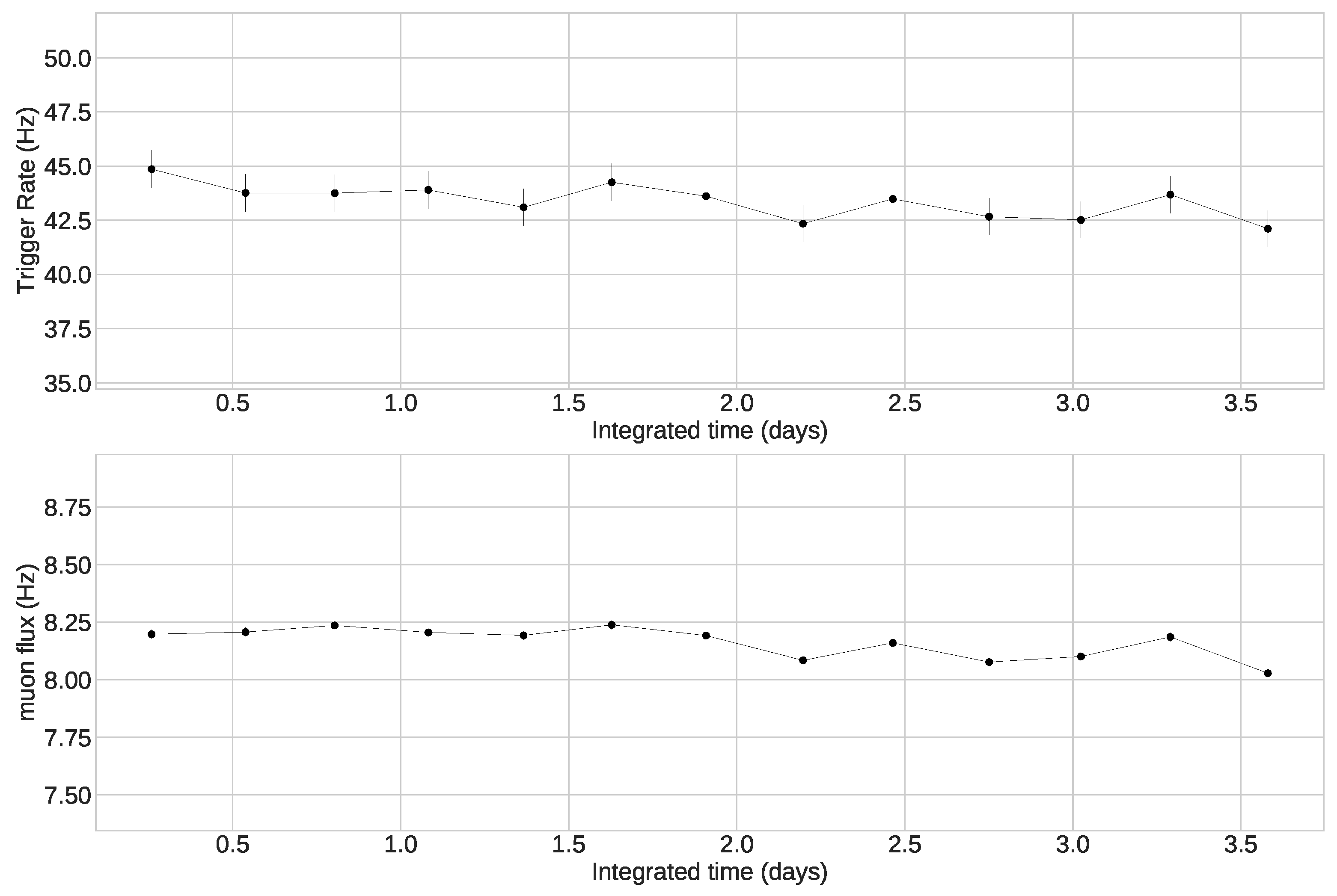
Performance of the detector has been tested first on a free-sky exposure. Installing the detector for about a week on the roof of the Physics department of the University of Naples Federico II, far away from any absorbing obstacle, a mean trigger rate (GT logic described in Equation (
1)) of about 38.4 Hz and maximum fluctuations within 6.4% have been measured.
The track reconstruction algorithm requires two “signal points” in the same events. A signal point is identified when at least a bar and an arc are hit simultaneously and are geometrically compatible, meaning that if we ideally divide the cylinder in four sections, corresponding to the four stacks of arcs, the bar and arc providing a signal must be part of the same section. Then, when two signal points are reconstructed in the same trigger event, a track is obtained as the line linking the barycenters of the two points.
Figure 4 shows the trigger rate and the track flux trends, as functions of the integrated acquisition time, divided in intervals of about 6 h. The muon rate is reduced with respect to the trigger rate to a mean of 8.2 Hz, mostly due to the tighter tracking requirements. Measured muon flux fluctuates within the 2%, improving the oscillations of the trigger rate, proving the robustness of the tracking algorithm.
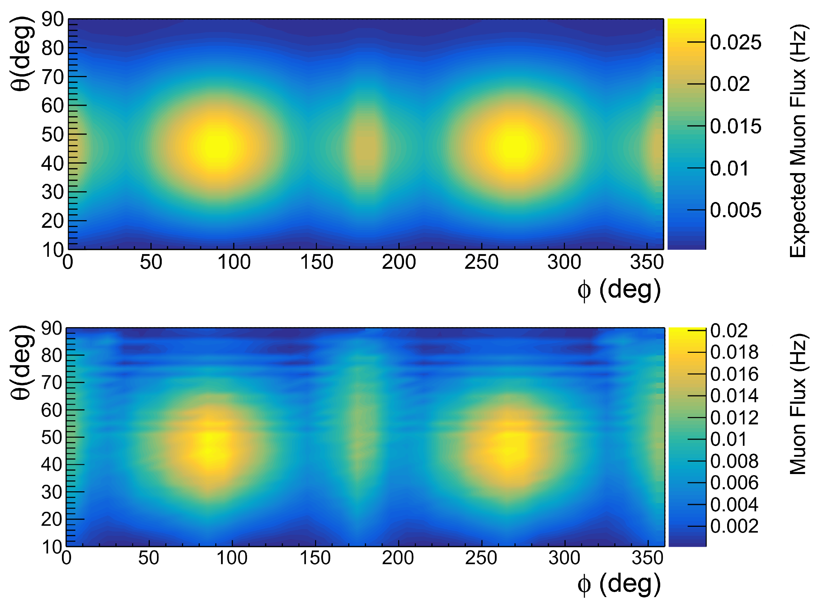
In order to compare the measured muon flux with expectations, a Monte Carlo simulation has been developed to verify the detector capabilities. The simulation provides a simple numerical evaluation of the geometrical acceptance and the muon flux is analytically calculated by integrating Gaisser’s modified formula [
6]. The results are reported as bidimensional map in
muon direction coordinates and shown in
Figure 5; the color scale represents the muon rate in Hz.
4. Validation On-Site
The detector was specifically built to fit into wells and to maximize efficiency under such conditions. However, it was decided to preliminarily test and study the detector’s performance in a known environment, where the detector’s ability to detect empty chambers in the overlying rock could be easily proven, even though it is not a borehole. The underground of the Mt. Echia, a hill in the core of the city of Naples (Italy), has been chosen as validation field. The site was partially probed with a planar muon detector in the past [
7,
8], reaching impressive results. Since large planar detectors, even being portable, are more difficult to move around, the previous experience with the MU-RAY apparatus only investigated two locations. The compactness and peculiar portability of the new cylindrical muon detector allows for easily relocation, useful in the case a three-dimensional image would be provided.
Mt. Echia is made of Neapolitan yellow tuff and hosts in its underground the so-called Galleria Borbonica (Bourbon tunnel), a tunnel linking the King’s palace to an escape exit on the opposite side of the city, built by order of king Ferdinando II of the Bourbon house. Furthermore, a complex and even more ancient system of galleries and chambers have been excavated and are partially available to the public. In this scenario, the detector was moved in different installation points, chosen around a known cavity, aiming to provide sufficient data to investigate possible improvement of the 3D reconstruction algorithm described in [
8].
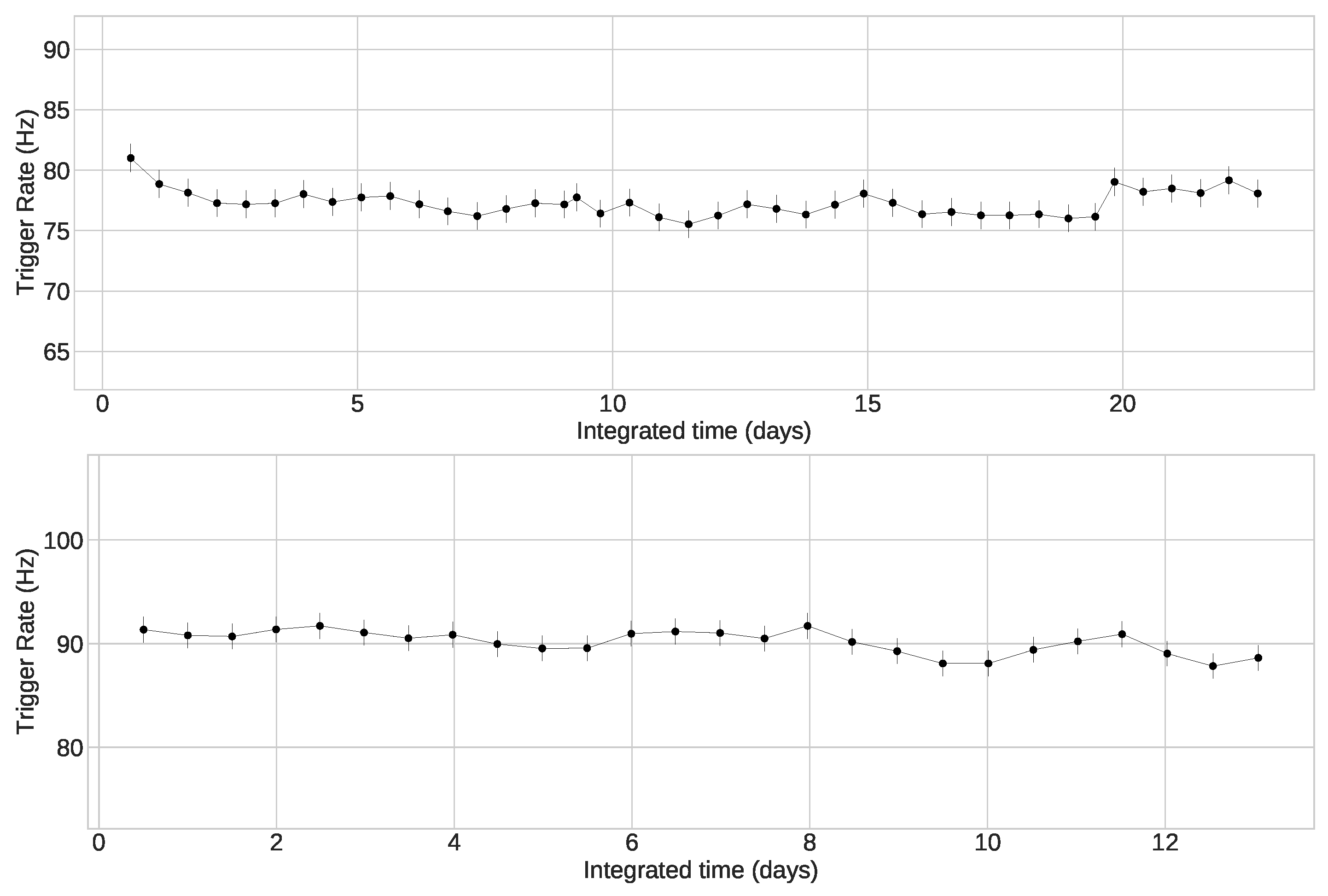
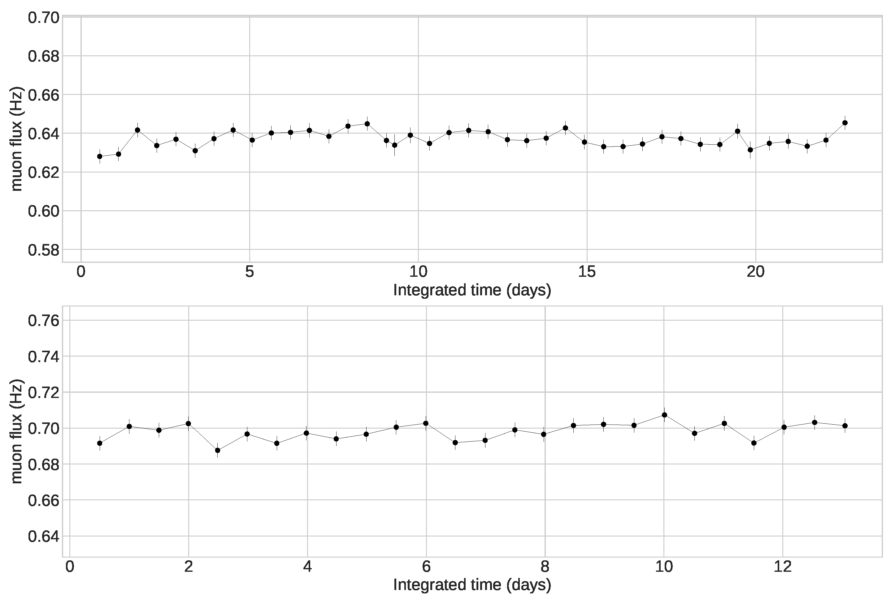
A first observation has been promptly seen: the underground trigger rates were higher than in free-sky exposition. In
Figure 6 two examples of trigger rate acquired in different underground locations are reported. The measured trigger rates are on average 90 and 77 Hz, while in the free-sky the mean trigger rate was almost half these values. Applying the tracking algorithm, the measured muon rates decrease to the level of about 0.69 and 0.64 Hz (
Figure 7), that are acceptable according to the expected rock absorption degree.
Investigating the origin of this over-triggering of the detector, we concluded that the most reasonable source activating the detector is environmental radioactivity, as is expected from simulations described in [
9]. As can be found in literature [
10], the volcanic yellow tuff contains many radioactive isotopes, as
Th,
Ra and
K. The decay chains of these elements led to production of
,
and
particles. Since the detector shell provides adequate shielding against alpha and beta particles, we are quite confident that the source of these signals are gammas. For instance
Th daughters
Bi,
Tl and
Ac produce gammas of 727, 860 and 911 keV respectively, energies high enough to fulfill the trigger requirement.
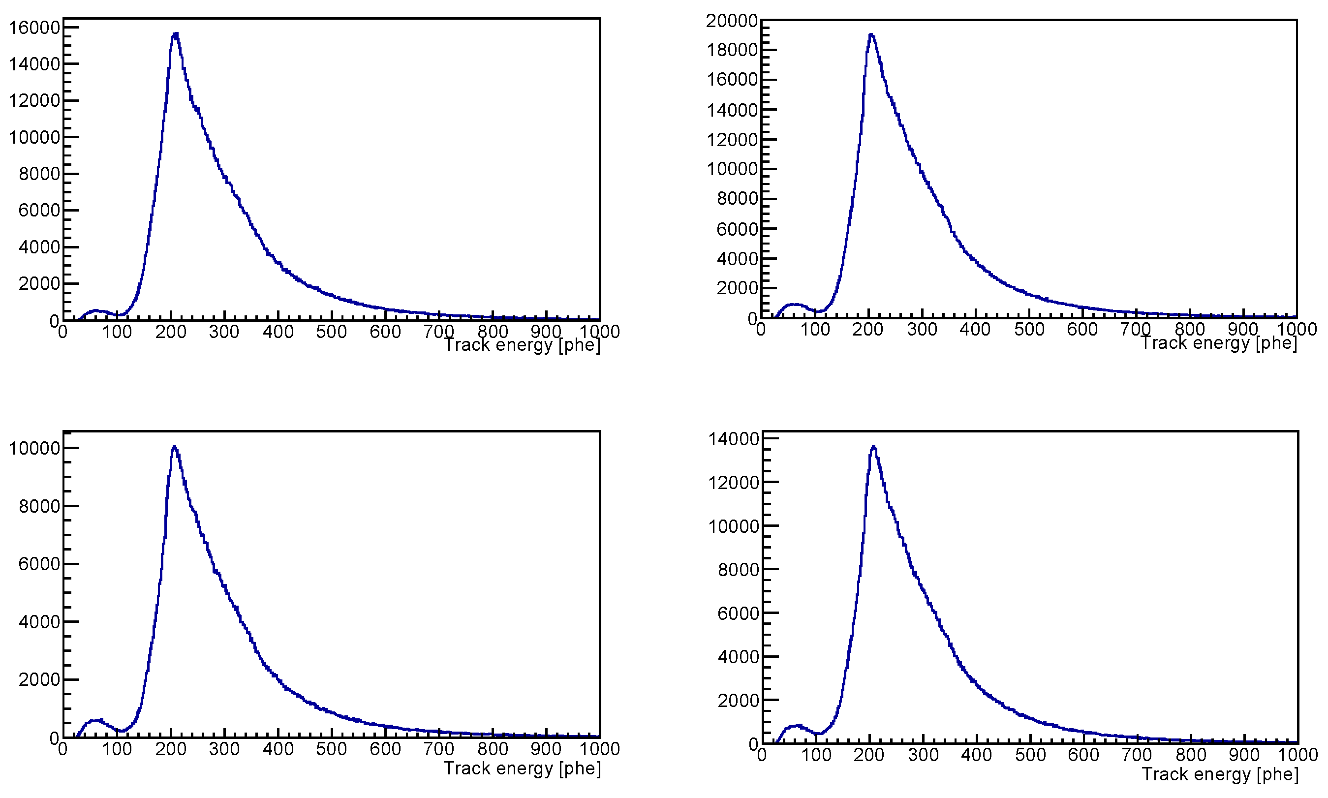
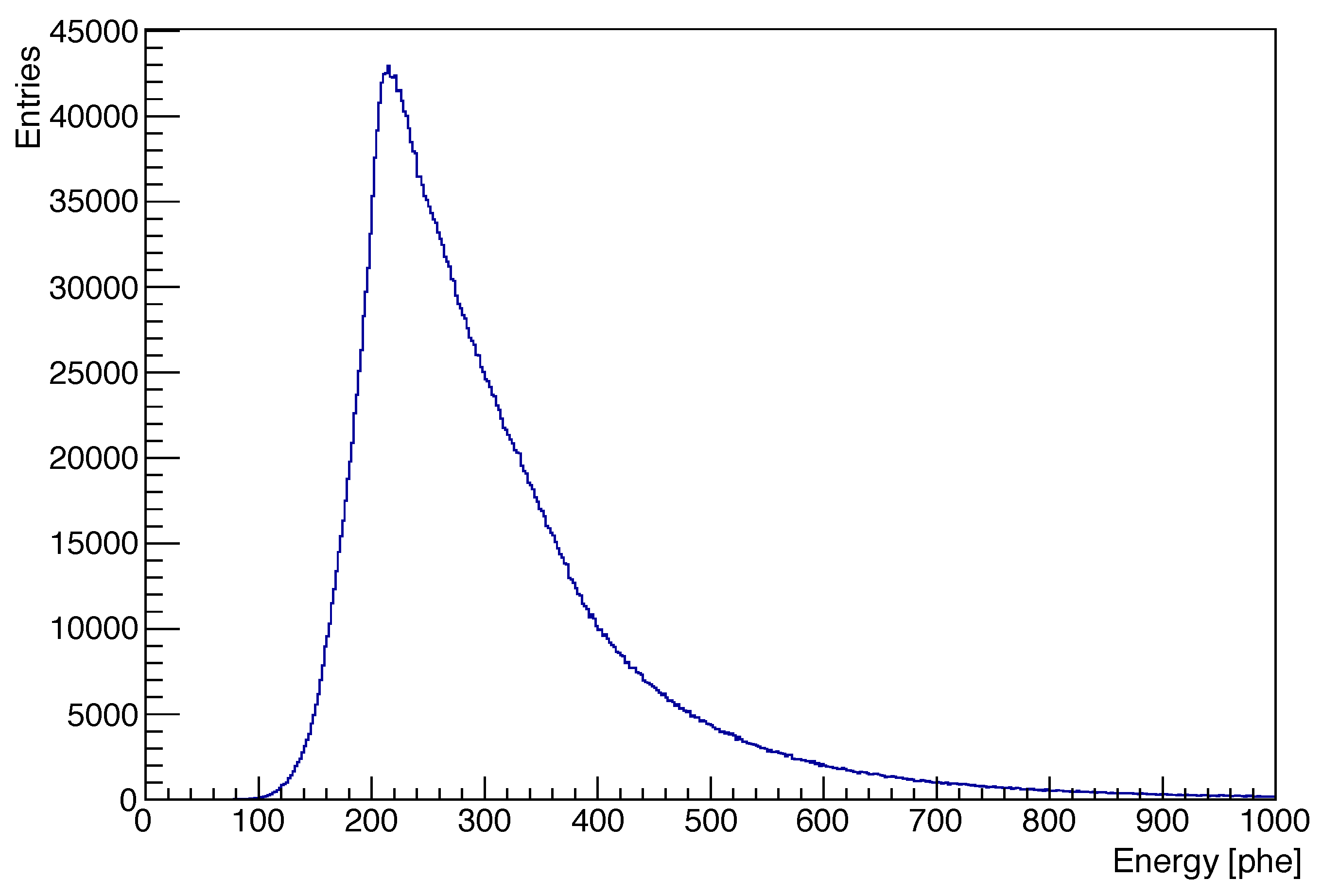
Even through the spurious signals are mostly removed applying the tracking algorithm, a small fraction of remaining contamination is spotted out in the track energy distributions. Indeed, as can be seen in
Figure 8, a second smaller peak is observed in addition to the principal one, related to muons. A countercheck of the falseness of these tracks is that this lower energy peak is not present in the energy distribution of the free-sky reconstructed tracks (
Figure 9).
Then, to reduce this background contamination to a level as low as possible we decided to apply an energy cut on the track energy in between the two observed peaks.
The stability of the measured muon flux and the lower level of fluctuations with respect to the trigger rate can be taken as a first meaningful demonstration of good performance of the detector and associated reconstruction algorithms. The underground muon rates shown in
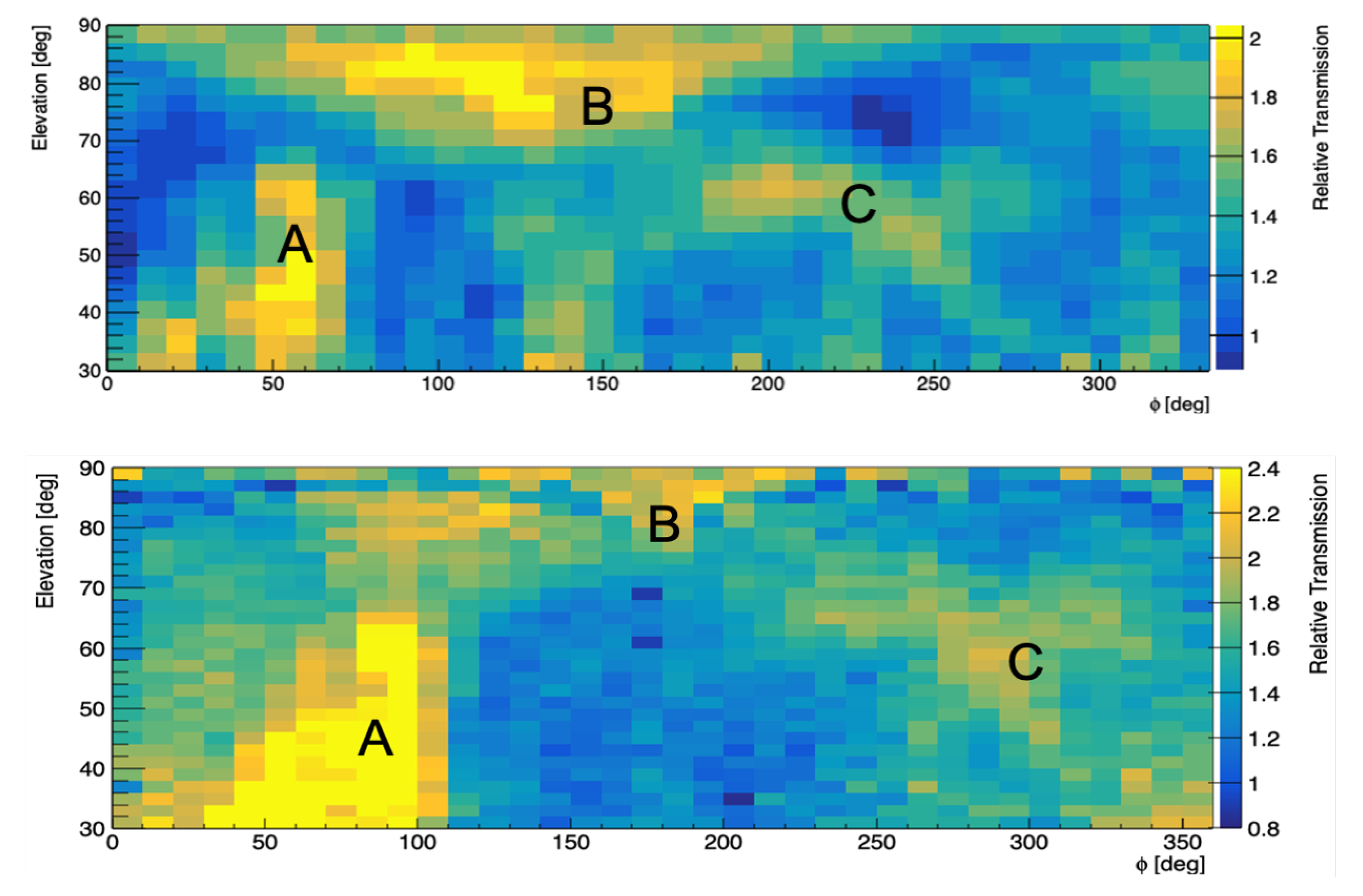
Figure 7, present maximum variations around the mean values under the level of 3%, almost halving the trigger rate fluctuations. All the datasets, taken in several different locations present similar behaviors. The capability of the borehole cylindrical detector to provide clear evidence of the presence of cavities in the inspected volumes has been proved by results of this first test on-field. In particular the first location where the detector has been installed corresponds to the already adopted location in the context of the MU-RAY experiment. A muon radiography study has been performed with an amount of data corresponding to about one week and the resulting image has been compared with what was already obtained with MU-RAY data. After accounting for slight differences in the positioning of the two detectors and polar inefficiencies of the borehole detector due to the PD angular gaps, identical structures appear to be identified by the bore-hole detector and the MU-RAY detector (
Figure 10). The evidence of corresponding signals, indicated as A, B and C, proves that performance of the new cylindrical detector in this scenario is compatible with ones of a planar 1 m
detector, even if the two compared images result from different amounts of data, that are about 5 and 20 days of data taking respectively for the cylinder and MU-RAY. Signals indicated in
Figure 10 have been also identified, by simulations, as known cavities. In particular the B and C correspond to the chambers chosen as test in [
7], while signal A corresponds to another known chamber, referred to as the “dome”.
Conclusions
Muon radiography is rapidly developing as an alternative and non-invasive tool to investigate the presence of cavities below large buildings or hills. One major difficulty of muon radiography in this application is related to the necessity of installing a muon detector deeper than the volumes to be inspected, meaning that an underground available and easily accessible space is required, and also a power supply system is needed to feed the apparatus.
In this paper, we describe a new compact, portable and low power consuming muon detector, recently developed for muon radiography application. The new borehole cylindrical detector has been particularly designed to be inserted in drilled wells, overcoming the problem of the installation point.
The sensitive surface of the detector has a cylindrical shape, realized by using arc-scintillators maximizing the acceptance of this geometry.
Tests have been conducted both exposing the detector to free sky muon flux and measuring underground muon transmission through tens of meters of rock. Good performance and stability were observed in both exposures. The capability of detecting the presence of cavities hidden in the rock has been validated in a preliminary field application.


 ,
, 


