
Commissioning Results of the New Compact ECR Ion Source for Electrostatic Storage Ring at KACST


King Abdulaziz City for Science and Technology (KACST), P.O. Box 6086, Riyadh 11442, Saudi Arabia
*
Author to whom correspondence should be addressed.
Instruments 2023, 7(1), 11; https://doi.org/10.3390/instruments7010011
Submission received: 21 November 2022
/
Revised: 12 February 2023
/
Accepted: 15 February 2023
/
Published: 23 February 2023
Abstract
:A compact microwave ECR ion source with low operating power was tested and commissioned for the ion injector line in the multipurpose low-energy ELASR storage ring facility at King Abdulaziz City for Science and Technology (KACST) in Riyadh. The compact ECR ion source can deliver singly charged ions with an energy of up to 50 keV and a beam current of up to 50 μA or up to 500 µA with a larger extraction aperture. The plasma in the ECR chamber is driven by a simple transmitter antenna, making the overall size of the ion source only 6 cm in diameter, which is relatively small when compared with other ECR systems. Additionally, the source operates without a high-voltage platform, which significantly reduces the overall footprint and simplifies the system operation. In this paper, the mechanical design and modeling of the ECR ion source are introduced, and the layout of the first part of the beam line is presented along with the numerical simulation results. In addition, the experimental results obtained for the first generated ion beam and commissioning of the ECR ion source are introduced and discussed.
1. Introduction
In the last 20 years, there has been growing interest in the use of electrostatic storage ring devices in many applications in atomic and molecular physics, as well as in biological and macroparticle sciences [1,2,3,4]. For instance, the storage ring can be equipped with either crossed- or merged-beam configurations or to perform different low-energy physics interactions, such as electron–ion, laser–ion, ion–ion, or ion–neutral collisions. An important feature that makes electrostatic storage rings very attractive devices is that there is no mass limitation for the stored ions because the electrostatic field rigidity () is mass-independent (, where T is the kinetic energy of the particle and q is the charge state).
The ELectrostAtic Storage Ring (ELASR) facility for atomic and molecular collisions has been designed and is currently under construction and final commissioning at the King Abdulaziz City for Science and Technology (KACST), Riyadh, Saudi Arabia [5,6,7]. As shown in Figure 1, the electrostatic storage ring is the core of the facility, and it is finally integrated with a versatile ion injector beam line. This injector was equipped with a high-resolution mass-analyzing magnet, which was designed to handle molecular ion masses of up to 1500 amu with a mass resolution of Δm/m = 1:1500 [8]. The ELASR storage ring is a prototype of the electrostatic storage ring (ELISA) at Arhus, Denmark [1]. The main difference between these two storage rings is in the type of the ion source as well as the use of a high-resolution magnet to provide the ELASR by selected ion molecular beams [1,5,6]. Moreover, our design features a rather significantly small deflection in a parallel plate deflector (PPD) with a deflecting angle of 7°. This is significantly smaller than the deflecting angle in existing rings, which range between 10° and 15°. This allows us to lower the switching voltage during beam injection and hence reduces switching times and injection effects.
A very compact microwave ECR ion source with low operating costs was integrated into a versatile ion injector beam line to provide the ELASR ring with the required ion beam. The ECR ion source provides singly charged ions to the ring with an energy of up to 50 keV, beam intensity of 107 ions/s, and beam emittance of 15 mm mrad (the beam energy at beam emittance of 15 mm mrad is 40 keV).
It is also intended to operate the ion source system and the following focusing and deflection system independently, as a single-pass experiment for different applications. In this case, the source can deliver a beam with an energy of up to 50 keV and a beam current of 50 μA or more, depending on the extraction aperture used. The scope of this contribution is to present the commissioning of a 50 keV ECR ion source and report the production of a high-beam transmission with good temporal stability.
2. ECR Ion Source Mechanical Design
The ECR ion source was mounted along the axis of the beamline injector in a separate vacuum chamber. Immediately after the ion source, an electrostatic Einzel lens system with two grounded electrodes and a central cylindrical electrode at a typical voltage of 50% of the source voltage was used to focus the ion beam radially. The Einzel lens system forms an integral part of the beam extraction system, with a focusing electrode in the ECR ion source. The ECR plasma is generated in the plasma chamber under the influence of a gradient magnetic field configuration. This is created by permanent magnets which are positioned around the chamber and microwave power in such a way that free electrons can absorb the microwave power and heat up to the point that they can ionize the gas molecules. This can be performed when the microwave frequency matches the angular frequency of electrons (resonances) [9]. The beam is then generated in the ECR plasma chamber and then shaped and transported to the Faraday cup, located 1200 mm away from the ECR plasma extraction port. The extraction system adopted provides flexibility by using a double extraction electrode on the source for beam extraction optics optimization.
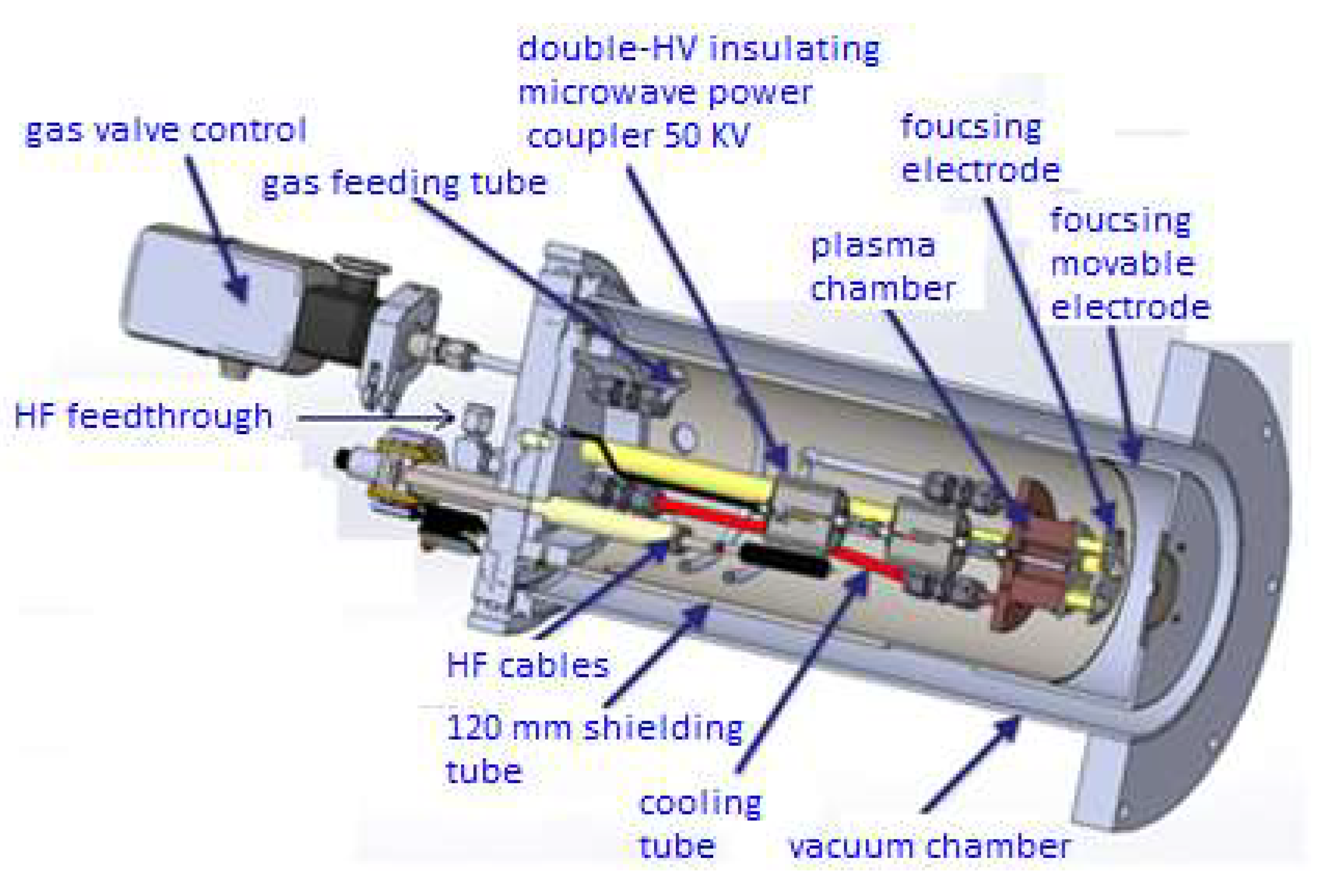
The ECR ion source is equipped with a gas flow control, two high-potential feedthrough ports for the source voltage (HV feedthrough) and the focusing electrode, a UHF signal feeding the source with a simple SMA coaxial cable, and input and output cooling pipes, as shown in Figure 2. The system does not require a high-voltage platform, which reduces the installation size and makes its operation safe and easy to use [10]. Inside the ECR chamber, a tube contains all the relevant components, namely, the gas feeding tubes, which are filled with Al2O3 powder to avoid the discharge condition tracking along the gas path into the plasma cylinder, and the UHF signal connector [11], which has two stages of insulation to avoid signal reflection. The tube and all the components were inserted into the CF160 vacuum chamber, and they were all fully under vacuum (between 10−6 up to 10−7 mbar). By comparing the current ion source to the old version (Cold Cathode Ions Source CCIS) which needs a high-voltage platform with isolators and transformer. In addition, it needs a high safety system and restricted regulations at high voltage values [12].
The geometry of the ECR plasma chamber was chosen to be as compact as possible, allowing for a reasonable power density and maintaining the Paschen conditions for plasma ignition. A quarter wave geometry at a frequency around 2.45 GHz was chosen for this purpose, which corresponds to an antenna of length about 27 mm. The power is distributed inside the plasma chamber volume by a single antenna of 27 mm length, which is surrounded by three grounded couplers antennas to minimize the required power needed to make plasma ignition. In order to create a magnetic field inside the plasma chamber, magnets are positioned around the chamber. The resulting magnetic field decreases gradient from the mid plane of the chamber towards the extraction plane. At the maximum region of the electric field created by the antenna, the electron cyclotron resonance (ECR) is placed (this is a patented work of microwave discharge system by Polygon Physics company) [13,14].
The design provided a single-stage beam acceleration of up to 50 keV. The beam generated in the ECR plasma chamber was focused by an electrostatic focusing electrode, which can be placed either 10 mm or 20 mm away from the ECR plasma extraction chamber port, depending on the beam requirements. The focusing electrode had an aperture of 8 mm in diameter and was floated to an adjustable potential of up to 50 kV. Following the focusing electrode, a grounded electrode with a 10 mm diameter aperture was attached to the housing tube within a positioning margin of up to 50 mm from the focusing electrode. The final assembly of the ECR ion source is illustrated in Figure 3.
Depending on what kind of ions will be extracted at a specific energy from the ion source, beam extraction will be optimized by a laterally movable electrode which also forms the first grounded electrode of the einzel lens. The detailed design of the ion extraction system was already described in [15].
3. Layout and Simulation of the First Part of the Ion Beam Injector Line
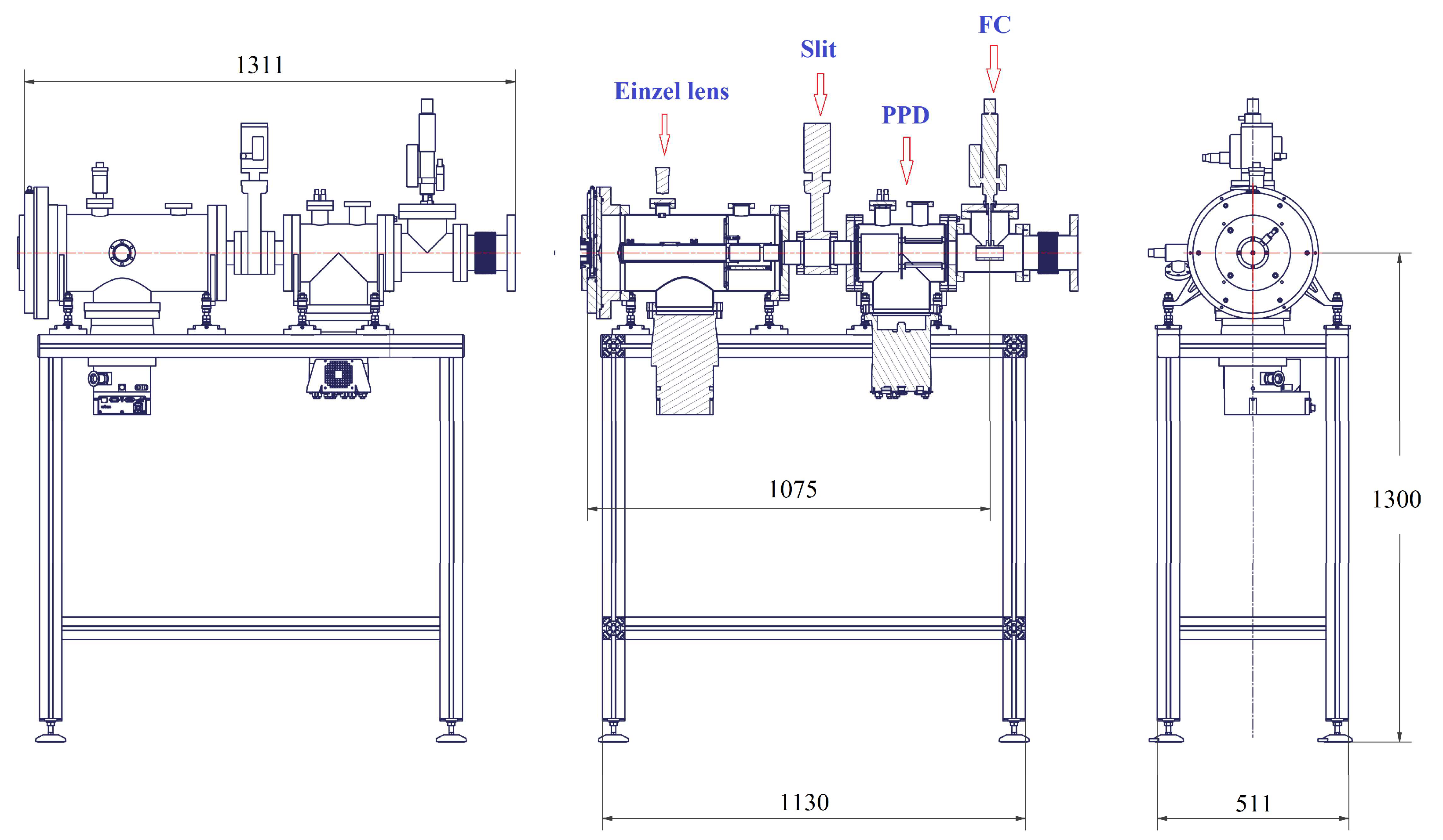
In this section, the first part of the single-pass beam line, which is used to transport and measure the first-ion beam current using the new ECR ion source, is presented. The layout of this section, along with its important components, is illustrated in Figure 4 (without the ion source chamber).
In this injection line, the ECR ion source and axial low-energy beam transport line are mainly composed of an einzel lens combined with an electrostatic quadrupole, a set of deflectors, and diagnostic devices. The deflector was used in a set of parallel-plate doublets, which allowed closed-orbit corrections in both the horizontal and vertical planes. One of the deflectors is used to chop ON and OFF the injection of the ion beam into the storage ring. The parallel plate deflector is located directly downstream from the einzel lens with a radius of 150 mm and plates at a distance of 50 mm [12]. The electrostatic quadrupoles doublets (QD) are used to defocus in one plane while focusing in others (QD was not used in this benchmark test) [5].
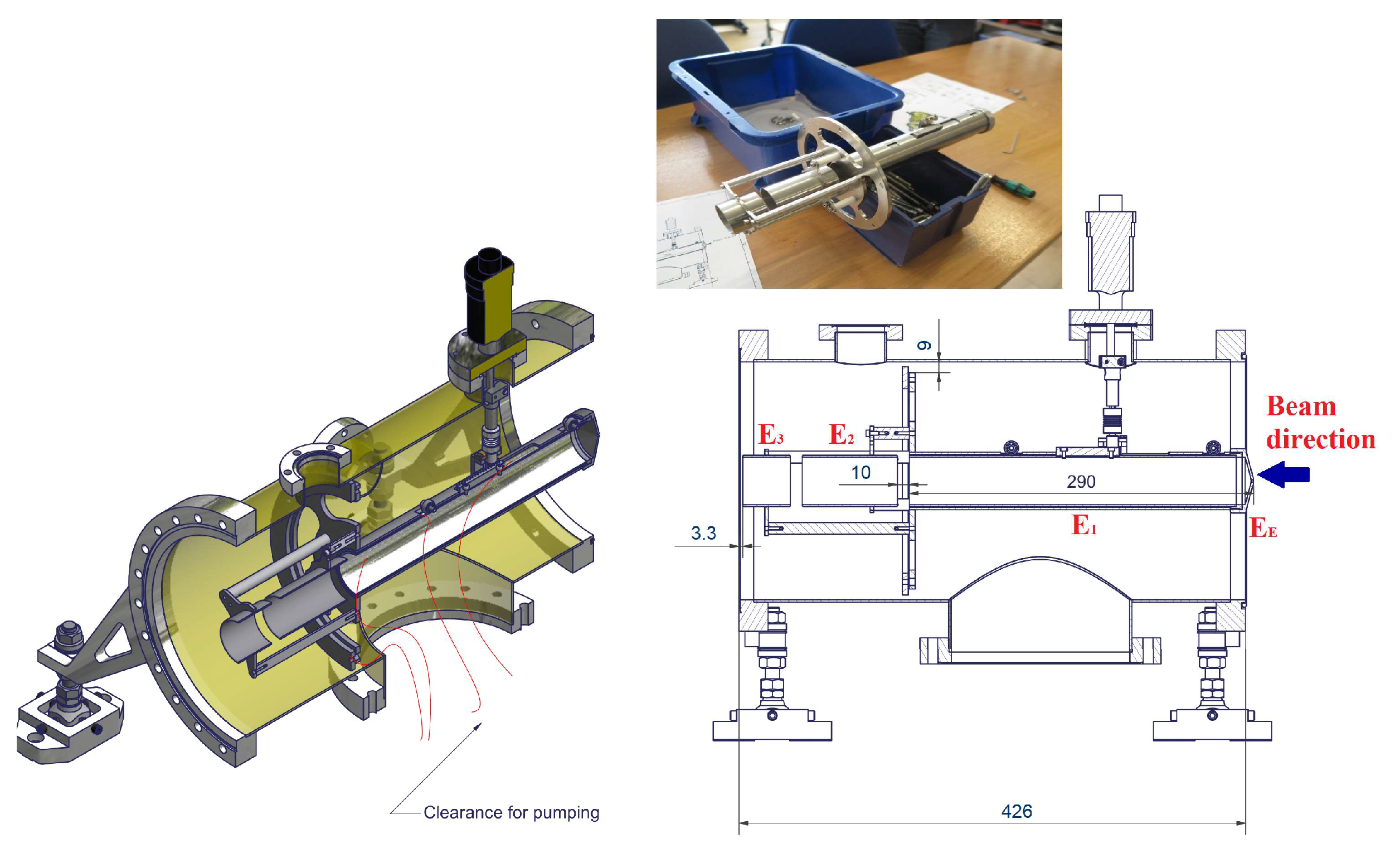
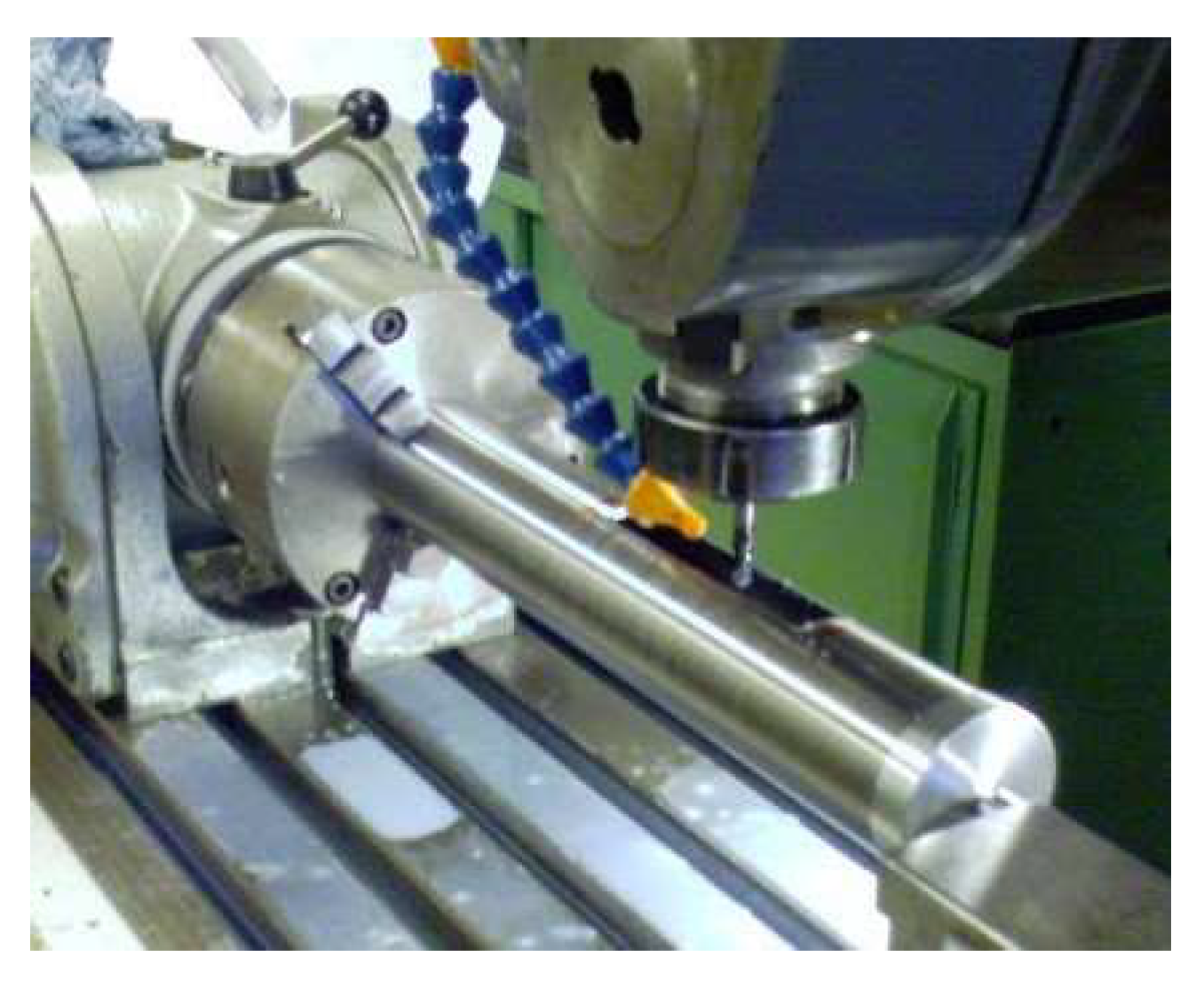
The extracted ion beam in this benchmark test was mainly focused by the einzel lens. Therefore, a technical drawing of these optics is shown in Figure 5. The inner diameter of the cylinders was 40 mm for a gap of 10 mm between the electrodes, and the distance between the last electrode and the exist flange is 3.3 mm. The optimal lengths of the cylinders were considered as E1 = 290 mm, E2 = 80 mm, and E3 = 40 mm for the inner, central, and outer electrodes, respectively. It should be mentioned here that the position of electrode E1 was adjustable within a margin of 40 mm. The photograph of the einzel lens movable electrode is also presented in Figure 6.
The design of the ion beam injector was developed with suitable ion optics simulation packages for tracking the ions along this part of the beam line. The Particle Beam Optics Laboratory PBO LabTM [16,17] is based on transport matrix R tracking code that makes use of the electrostatic palette TRACE 3-D, thereby allowing the tracking of ions in electrostatic fields.
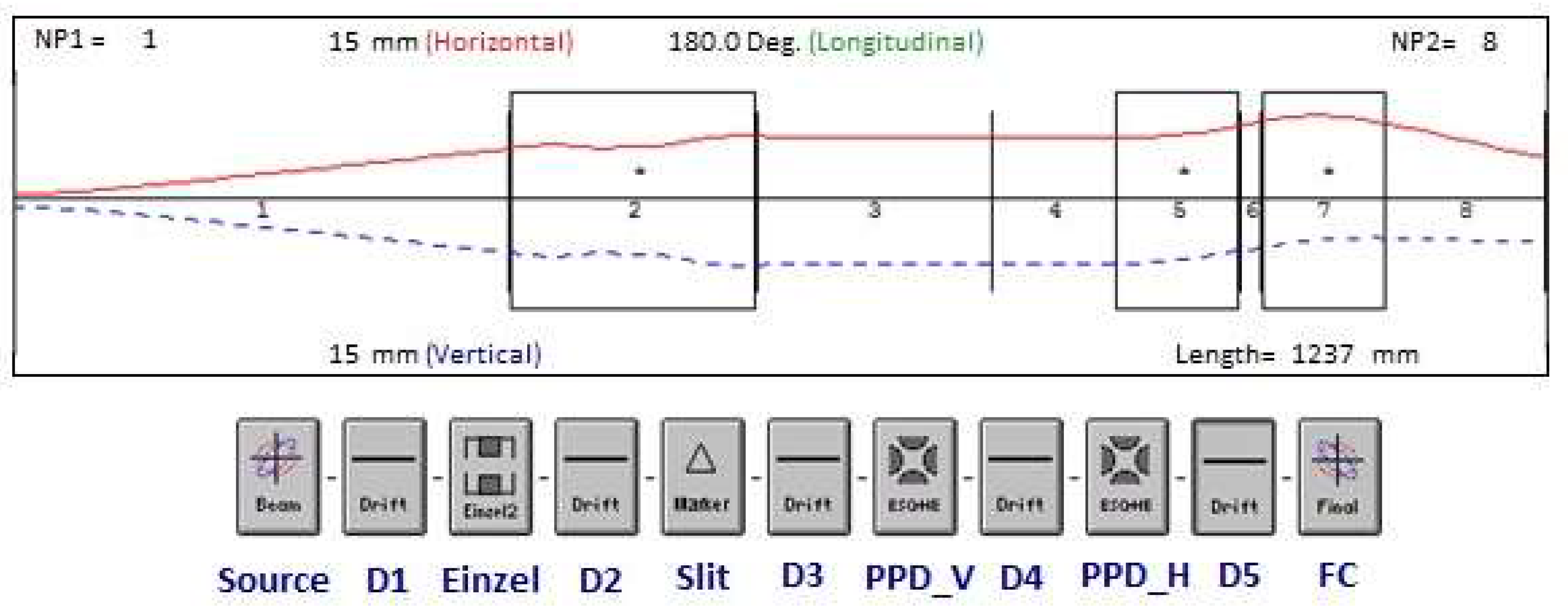
In this simulation, the initial parameters of the beam were applied with an emittance of 15 π mm mrad (the emittance was measured based on specification of the beam at the entrance slit where it was fixed for an elliptically shaped beam), a kinetic energy of 40 keV, and ion current of 34 µA. The extracted ions spread across the extraction electrode of the ECR ion source during the acceleration. The ion beam is then focused by the einzel lens in combination with parallel-plate deflector optics, which are also used to shape the beam. Finally, the ion beam at this stage of commissioning was collected using a Faraday cup (FC), which was located downstream from the ECR ion source to measure the ion beam current. Figure 7 shows the beam envelope tracked through this part of the ion beam injector line from the ion source to the first Faraday cup, including five drifts space (D1, D2, D3, D4, and D5) and other optics (einzel lens, slit and PPD).
4. Commissioning Results and Discussion
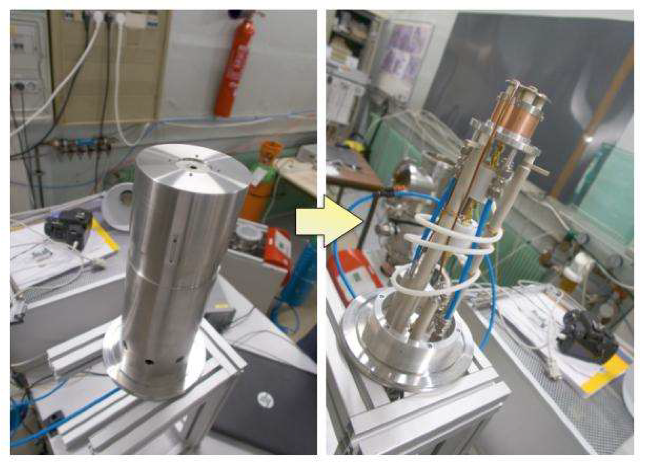
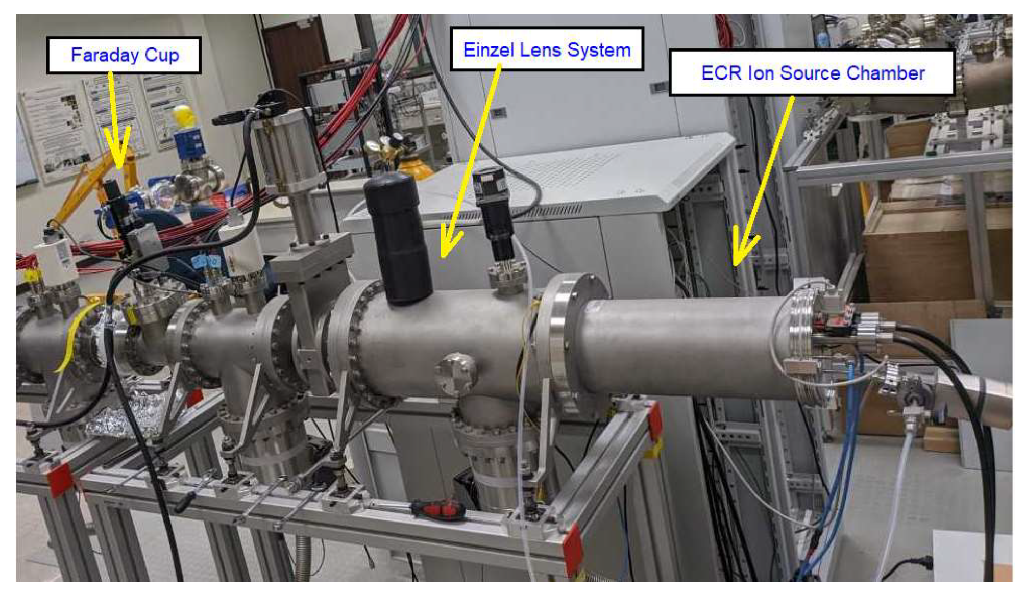
The ECR ion source was developed for the ELASR ring facility in collaboration with polygon physics. The 50 kV ECR ion source was mounted along the axis of the beam injector line, as shown in Figure 8. Two vacuum pumps were used to provide vacuum down to 4 × 10⁻⁷ mbar (the pressure in the ECR ion source after injecting the Ar gas is in the range of 10−6 mbar). The extracted ion beam from the ECR ion source is focused, shaped, and transported to the Faraday cup location using an einzel lens.
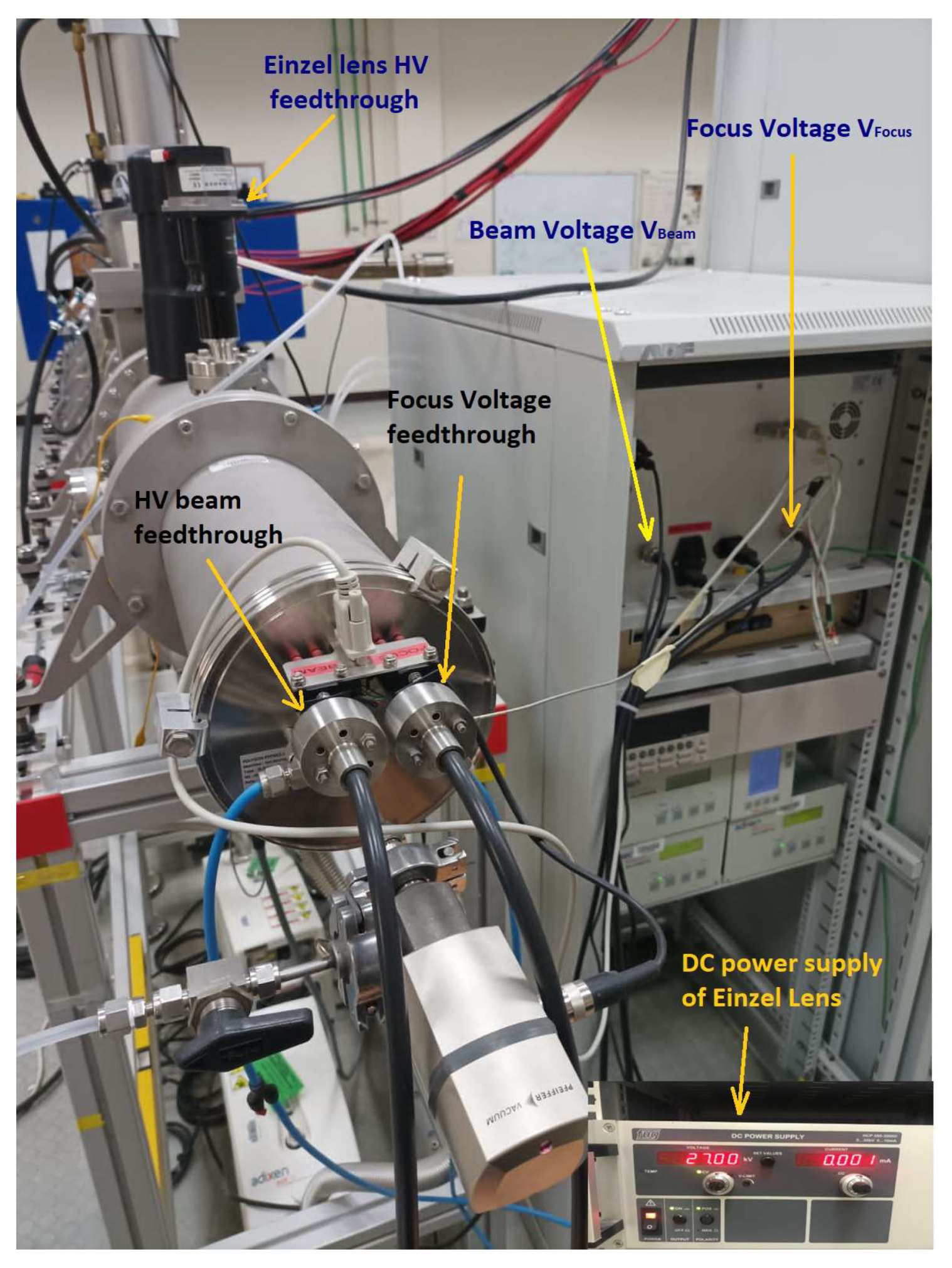
The test was repeated for different nominal injection beam energies of 20 keV, 30 keV, 40 keV, and 50 keV for an Ar+ ion beam. Ar gas was injected into the ECR plasma chamber and the UHF power was coupled to the central antenna to ignite the plasma. The typical UHF signal power used for this purpose was approximately 3 W. After a few minutes, the gas flow into the source became stable because of the low conductance of the gas cartridge, so that the corresponding acceleration voltage (VBeam) could be applied to the ECR plasma chamber and the beam could be extracted under steady conditions. Figure 9 shows the photography of the power supplies for the ion source and einzel lens.
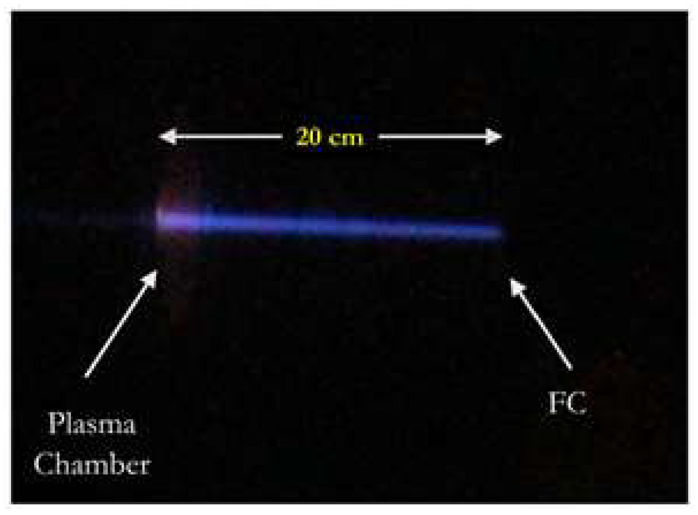
Following this step, a voltage (typically 10% less than the applied acceleration voltage) was then applied to the ECR focusing electrode to focus and shape the extracted beam. A photograph of the beam captured from the glass viewport is shown in Figure 10.
The einzel lens voltage was then set to an optimal value (approximately 50% of the applied acceleration voltage). The extracted ion beam from the ECR ion source was then transported to the first Faraday cup with a 24 mm diameter entrance aperture located 1200 mm from the ECR plasma extraction port. The current recorded by the Faraday cup (IFC) was compared with the power supply current (IPS) to quantify beam transmission efficiency.
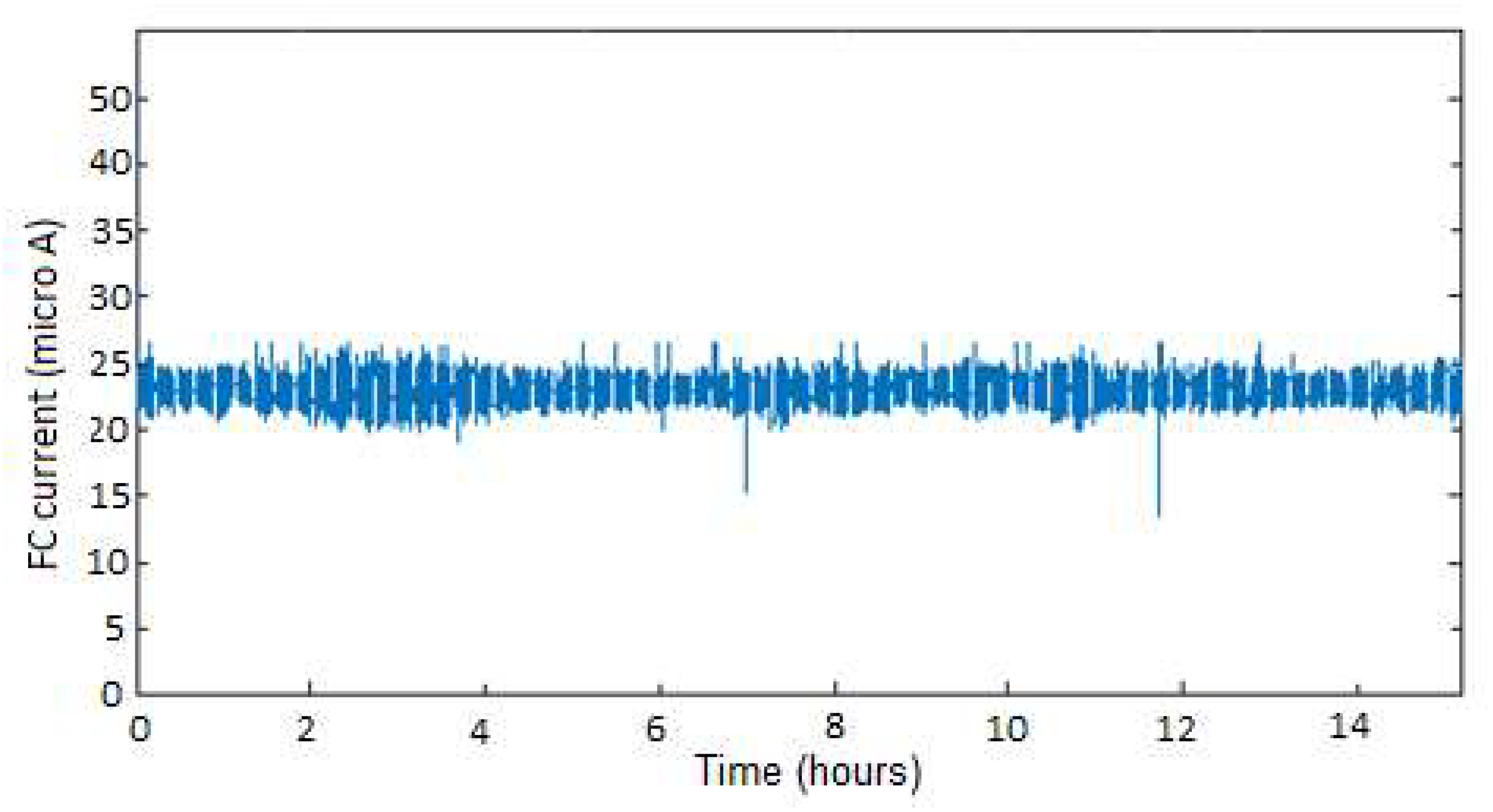
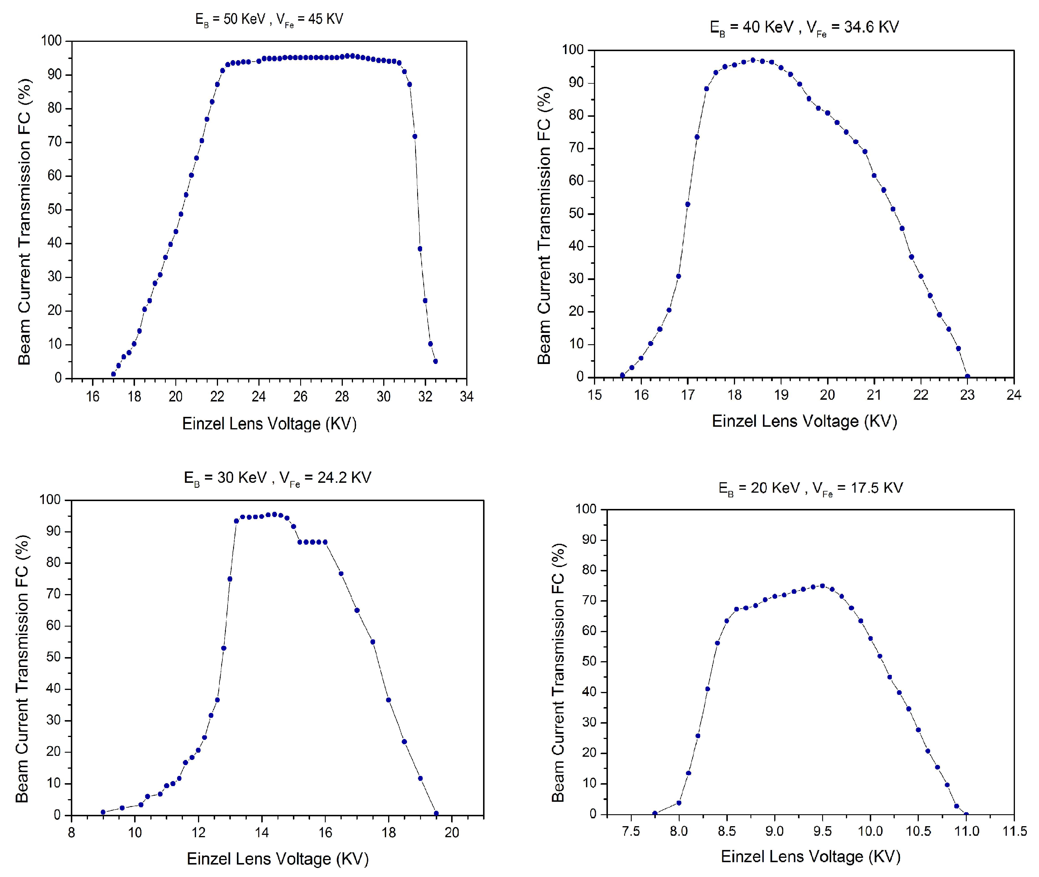
In this commissioning test, the objective was to generate an ion beam from the new ECR ion source and characterize the focusing voltage required for the einzel lens to achieve full beam transmission at the Faraday cup location. The voltage applied to the einzel lens was varied for a fixed beam energy and focusing electrode voltage, and the resulting current on the Faraday cup was measured. The test was conducted for a fixed power supply current (IPS) for each given beam energies (20, 30, 40, and 50 KeV). The beam current was measured using the given beam energy (EBeam), and the ion current in the Faraday cups (IFC) was measured as a function of the einzel lens voltage (VEinzel). A recording of the FC current over 15 h is shown in Figure 11, indicating the stability of the source over the operating time. Figure 12 shows the typical tests dealing with the characterization of einzel lens voltages, examining their extraction and focusing efficiencies at the chosen beam energy and focusing electrode settings. From the plots, one can observe the region where the einzel lens voltage is optimal for different nominal beam energies. By comparing these obtained results with the numerical simulation results, it can be also seen that most of the transferred ion beam is collected into the first Faraday cup. In principle, a reasonable agreement was found between these two results.
Figure 12 shows how the Faraday cup current (IFC) increases with increasing of the applied voltage on the einzel lens (VEinzel). This increase continues until the VEinzel values are approximately half of the applied acceleration voltage. The result is that the recorded IFC values are close to the actual value of the power supply current (IPS).
5. Conclusions
The use of a very compact ECR ion source shows that a high-voltage injection system can be built without the complications of a high-voltage platform. This simplifies the access and overall cost of such injectors. In addition, the obtained results show that over the first meter of the beam line, more than 90% transmission of the beam extracted from the source can be achieved with good temporal stability. The numerical simulation results using PBO-Lab software (beam envelope plot at beam kinetic energy of 40 KeV) for tracking the ion beam through the first part of the beam line injector are presented. The whole beam line system is currently connected to the mass-analyzing magnet. The next step is to run the ion beam injector line in combination with this magnet to analyze and separate the molecular ions.
Author Contributions
S.A.: conceptualization, methodology, validation, formal analysis, investigation, writing—original draft, writing—review and editing, supervision, funding acquisition; A.J.: methodology, validation, investigation, results interpretation, writing—review; S.J.: methodology, validation, working on software, data analysis; A.A.: methodology, validation, data analysis. All authors have read and agreed to the published version of the manuscript.
Funding
This research received a fund from King Abdulaziz City for Science and Technology (KACST) under project No: 20-0219.
Data Availability Statement
The data presented in this study are available on request from the corresponding author.
Acknowledgments
The project team would like to thank King Abdulaziz City for Science and Technology (KACST) for funding this work. Mohammed Al-Malki is warmly thanked for his great effort in this project. The POLYGON PHYSICS team is also warmly thanked.
Conflicts of Interest
The authors declare no conflict of interest.
References
- Møller, S. ELISA and electrostatic storage ring for atomic physics. Nucl. Instrum. Methods Phys. Res. Sect. A Accel. Spectrometers Detect. Assoc. Equip. 1997, 394, 281–286. [Google Scholar] [CrossRef]
- Nakano, Y.; Morimoto, W.; Majima, T.; Matsumoto, J.; Tanuma, H.; Shiromaru, H.; Azuma, T. A cryogenic electrostatic storage ring project at RIKEN. J. Phys. Conf. Ser. 2012, 388, 142027. [Google Scholar] [CrossRef] [Green Version]
- Schmidt, H.T.; Thomas, R.D.; Gatchell, M.; Rosén, S.; Reinhed, P.; Löfgren, P.; Brännholm, L.; Blom, M.; Björkhage, M.; Bäckström, E.; et al. First storage of ion beams in the Double Electrostatic Ion-Ring Experiment: DESIREE. Rev. Sci. Instrum. 2013, 84, 055115. [Google Scholar] [CrossRef] [PubMed] [Green Version]
- Jinno, S.; Takao, T.; Omata, Y.; Satou, A.; Tanuma, H.; Azuma, T.; Shiromaru, H.; Okuno, K.; Kobayashi, N.; Watanabe, I. TMU electrostatic ion storage ring designed for operation at liquid nitrogen temperature. Nucl. Instrum. Methods Phys. Res. Sect. A Accel. Spectrometers Detect. Assoc. Equip. 2004, 532, 477–482. [Google Scholar] [CrossRef]
- El Ghazaly, M.; Alshammari, S.; Welsch, C.; Alharbi, H. Design of a novel electrostatic ion storage ring at KACST. Nucl. Instrum. Methods Phys. Res. Sect. A Accel. Spectrometers Detect. Assoc. Equip. 2013, 709, 76–84. [Google Scholar] [CrossRef] [Green Version]
- El Ghazaly, M.O.A.; Behery, S.A.; Almuqhim, A.A.; Almalki, M.H.; Alshammari, S.M.; Alrashdi, A.O.; Alamer, H.S.; Jabr, A.S.; Lanazi, A.Z. An ion-beam injection line for the ELASR storage ring at KACST. Nucl. Instrum. Methods Phys. Res. Sect. A Accel. Spectrometers Detect. Assoc. Equip. 2016, 806, 36–42. [Google Scholar] [CrossRef]
- El Ghazaly, M.O.A. ELASR—An electrostatic storage ring for atomic and molecular physics at KACST. Results Phys. 2015, 5, 60–61. [Google Scholar] [CrossRef]
- El Ghazaly, M.O.; Dehnel, M.; Defrance, P. Development of a High Resolution Analyzing Magnet System for Heavy Molecular Ions. Phys. Procedia 2015, 66, 10–15. [Google Scholar] [CrossRef] [Green Version]
- Angot, J.; Bonny, L.; Jacob, J.; Lamy, T.; Sole, P.; Thuillier, T.; Villa, F.; Sortais, P. Development of a new compact 5.8 GHz ECR Ion Source. In Proceedings of the ECRIS2016, Busan, Republic of Korea, 28 August–1 September 2016. [Google Scholar]
- El Ghazaly, M.O.A.; Behery, S.A.; Almuqhim, A.A.; Papash, A.I.; Welsch, C.P. A versatile Ion Injector at KACST. AIP Conf. Proc. 2011, 1370, 272. [Google Scholar]
- IE-GUN|ECR Source for High Energy Beams-Polygon Physics. Available online: https://polygonphysics.com/products/ie-gun/ (accessed on 9 January 2023).
- El Ghazaly, M.; Almukhem, A.; Mandil, A.; Papash, A.; Welsch, C. Low Energy Ion Injector at Kacst. In Proceedings of the IPAC’10, Kyoto, Japan, 23–28 May 2010. [Google Scholar]
- Sortais, P.; Lamy, T.; Médard, J.; Angot, J.; Sudraud, P.; Salord, O.; Homri, S. Technical use of compact micro-onde devices. Rev. Sci. Instrum. 2012, 83, 02B912. [Google Scholar] [CrossRef] [PubMed]
- Sortais, P.; Lamy, T.; Médard, J.; Angot, J.; Latrasse, L.; Thuillier, T. Ultracompact/ultralow power electron cyclotron resonance ion source for multipurpose applications. Rev. Sci. Instrum. 2010, 81, 02B314. [Google Scholar] [CrossRef] [PubMed]
- El Ghazaly, M.A.; Aleksandrov, V.; Almukhem, A.A.; Alzeanidi, A.A.; Papash, A.; Welsch, C.P. Design of a versatile injector for a low-energy experimental platform at KACST. In Proceedings of the European Particle Accelerator Conference, Genoa, Italy, 23–27 June 2008. [Google Scholar]
- Particle Beam Optics Laboratory PBO-LabTM. Available online: http://www.ghga.com/accelsoft/pbolab.html (accessed on 28 August 2022).
- Brown, N.A.; Lampel, M.C. The Particle beam optics laboratory (PBO LAB™): A new education and training AID. In Proceedings of the Sixth European Particle Accelerator Conference, Stockholm, Sweden, 22–26 June 1998. [Google Scholar]
Figure 1.
Overview of the ELASR facility structure.

Figure 2.
CAD drawing of the ECR and its internal components.

Figure 3.
The final assembly of the ECR system.

Figure 4.
Layout of the first part of the single-pass ions beam injector line which contains an einzel lens, a slit, a parallel plate deflector (PPD), and a Faraday cup (FC).
Figure 4.
Layout of the first part of the single-pass ions beam injector line which contains an einzel lens, a slit, a parallel plate deflector (PPD), and a Faraday cup (FC).

Figure 5.
Technical drawing of the electrostatic einzel lens. EE, E1, E2, and E3 are the extraction electrode, first ground electrode, central cylindrical electrode, and second ground electrode of the Einzel lens, respectively. The top picture shows the real einzel lens electrodes.
Figure 5.
Technical drawing of the electrostatic einzel lens. EE, E1, E2, and E3 are the extraction electrode, first ground electrode, central cylindrical electrode, and second ground electrode of the Einzel lens, respectively. The top picture shows the real einzel lens electrodes.

Figure 6.
Photograph of the manufacturing of movable electrode of the Einzel lens.

Figure 7.
Overview of the ion beam envelope tracked along the first part of the ion beamline, as produced by PBO-Lab software. The most divergent beam in the horizontal (Red) and vertical (Blue) plane at beam energy of 40 KeV is x = 15 mm, y = 15 mm (for more details see [16,17]).

Figure 8.
The 50 kV ECR ion source mounted along with the axial adaptation of the beam injector line, containing the einzel lens system and a Faraday cup.
Figure 8.
The 50 kV ECR ion source mounted along with the axial adaptation of the beam injector line, containing the einzel lens system and a Faraday cup.

Figure 9.
Photography for the two power supplies of the ion source and einzel lens.

Figure 10.
Typical ion beam produced by the ECR ion source at the Faraday cup 20 cm downstream from the extraction port (Ar+, 50 keV, 45 kV focusing electrode, UHF power = 2 W, 40 .
Figure 10.
Typical ion beam produced by the ECR ion source at the Faraday cup 20 cm downstream from the extraction port (Ar+, 50 keV, 45 kV focusing electrode, UHF power = 2 W, 40 .

Figure 11.
A simple recording of the FC current over the time (Ar+1, EBeam = 50 keV, voltage of the focusing electrode = 45 kV, VEinzel = 25 kV voltage on the einzel lens = 20.25 KV, UHF power = 2 W, beam current ~ 23 .
Figure 11.
A simple recording of the FC current over the time (Ar+1, EBeam = 50 keV, voltage of the focusing electrode = 45 kV, VEinzel = 25 kV voltage on the einzel lens = 20.25 KV, UHF power = 2 W, beam current ~ 23 .

Figure 12.
The results of benchmark tests of the ECR ion source with the characterization of einzel lens voltages, VEinzel, as a function of the beam current transmission.
Figure 12.
The results of benchmark tests of the ECR ion source with the characterization of einzel lens voltages, VEinzel, as a function of the beam current transmission.

Disclaimer/Publisher’s Note: The statements, opinions and data contained in all publications are solely those of the individual author(s) and contributor(s) and not of MDPI and/or the editor(s). MDPI and/or the editor(s) disclaim responsibility for any injury to people or property resulting from any ideas, methods, instructions or products referred to in the content. |
© 2023 by the authors. Licensee MDPI, Basel, Switzerland. This article is an open access article distributed under the terms and conditions of the Creative Commons Attribution (CC BY) license (https://creativecommons.org/licenses/by/4.0/).
Share and Cite
MDPI and ACS Style
Alshammari, S.; Jabr, A.; Jaddua, S.; Alabadusalam, A. Commissioning Results of the New Compact ECR Ion Source for Electrostatic Storage Ring at KACST. Instruments 2023, 7, 11. https://doi.org/10.3390/instruments7010011
AMA Style
Alshammari S, Jabr A, Jaddua S, Alabadusalam A. Commissioning Results of the New Compact ECR Ion Source for Electrostatic Storage Ring at KACST. Instruments. 2023; 7(1):11. https://doi.org/10.3390/instruments7010011
Chicago/Turabian StyleAlshammari, Suliman, Abdullh Jabr, Saad Jaddua, and Abdulhakim Alabadusalam. 2023. "Commissioning Results of the New Compact ECR Ion Source for Electrostatic Storage Ring at KACST" Instruments 7, no. 1: 11. https://doi.org/10.3390/instruments7010011