
Ligamentum Flavum Rupture by Epidural Injection Using Ultrasound with SMI Method
 , , and
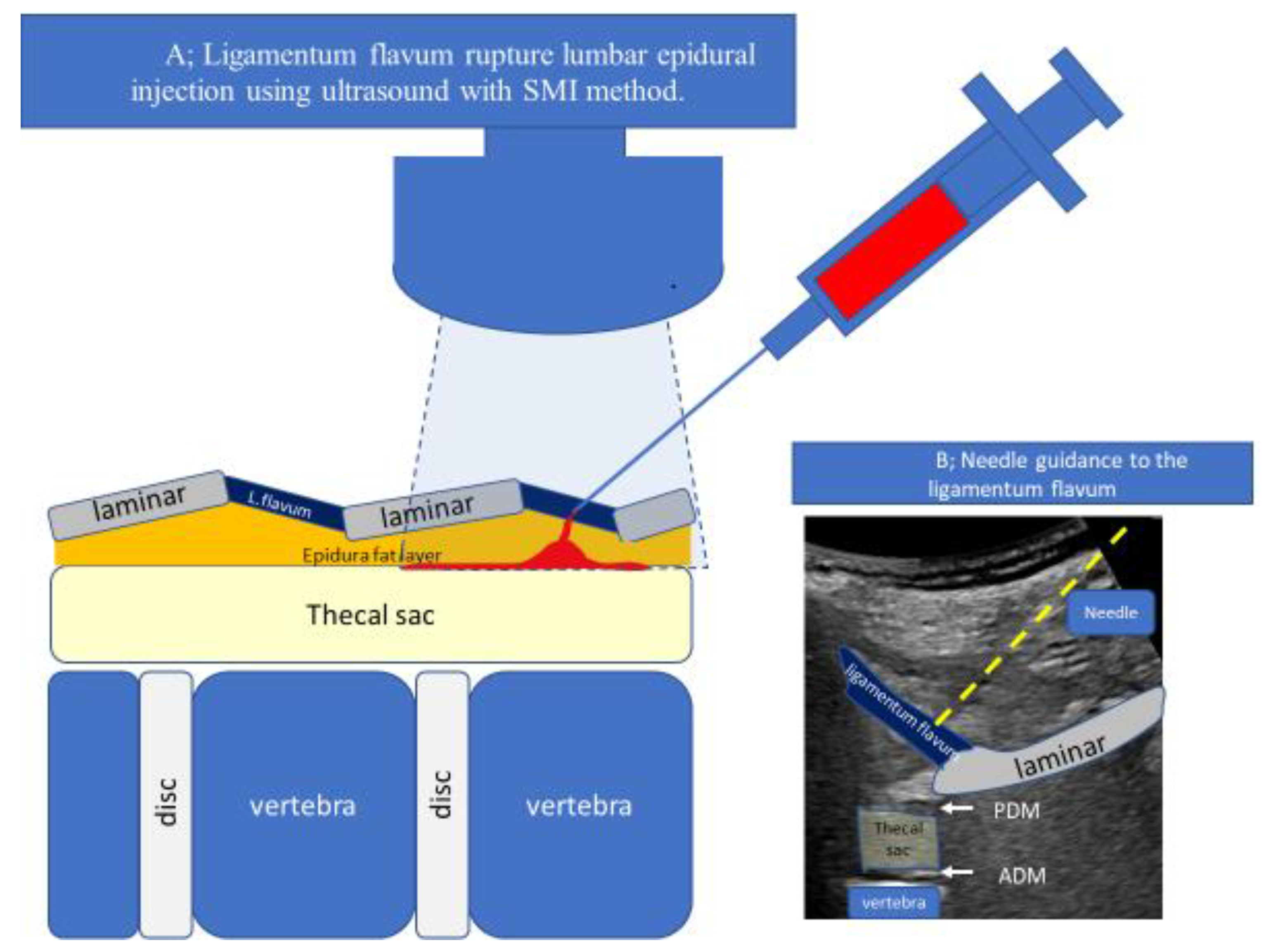
Abstract
:1. Introduction
2. Technique Description
3. Case Reports
4. Discussion
- Guide the needle into the ligamentum flavum.
- Advance the needle to the depth where resistance disappears (LOR).
- Confirm that the site of LOR is the epidural space.
- Confirm that the drug solution is appropriately distributed into the epidural space.
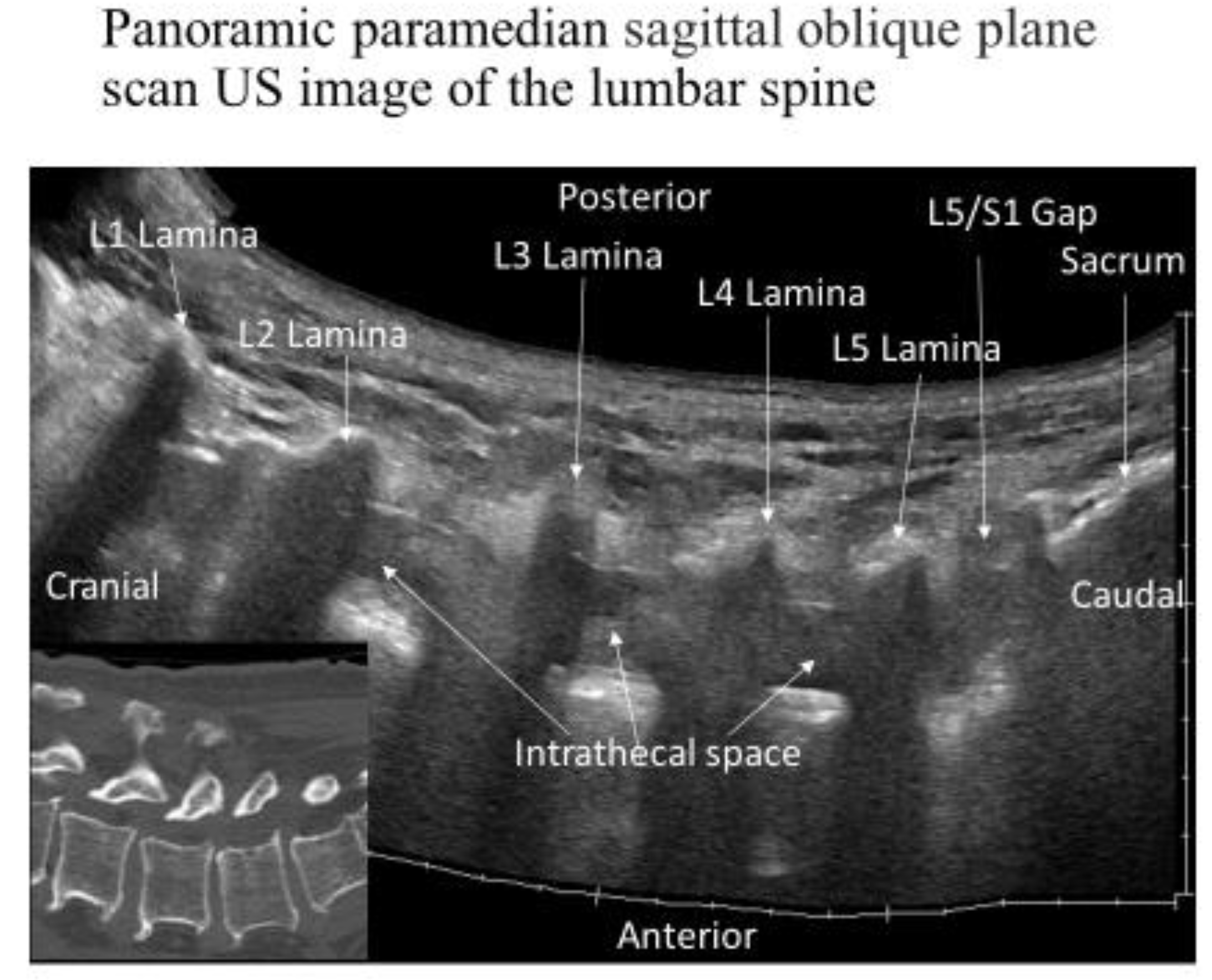
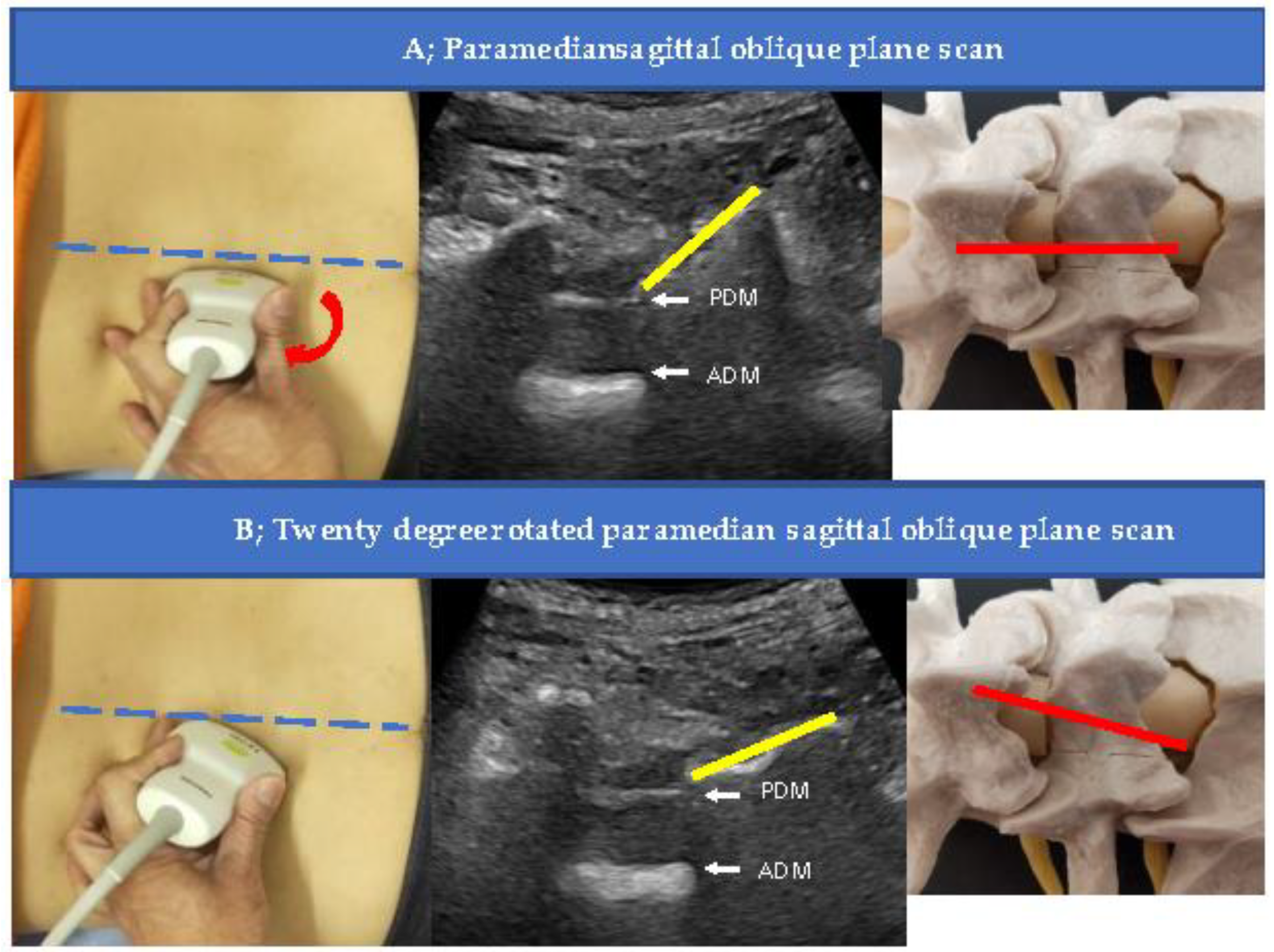
4.1. Measurement of Epidural Space Depth and the Proper Needle Angle (Needle Guide)
4.2. US-Guided Techniques
4.3. Capture Pressure Changes Using Devices
4.4. Devices to Accurately Capture the Needle Tip
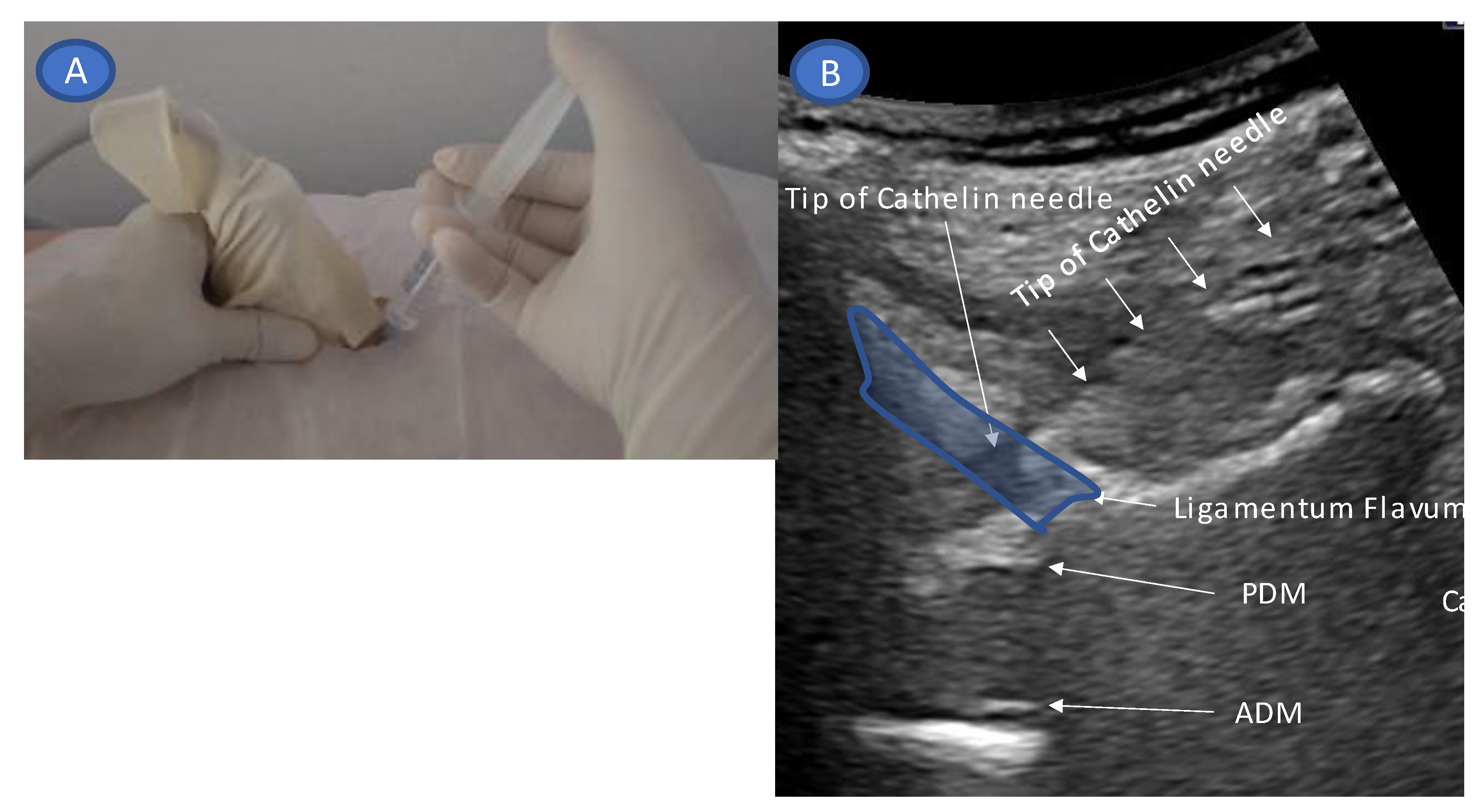
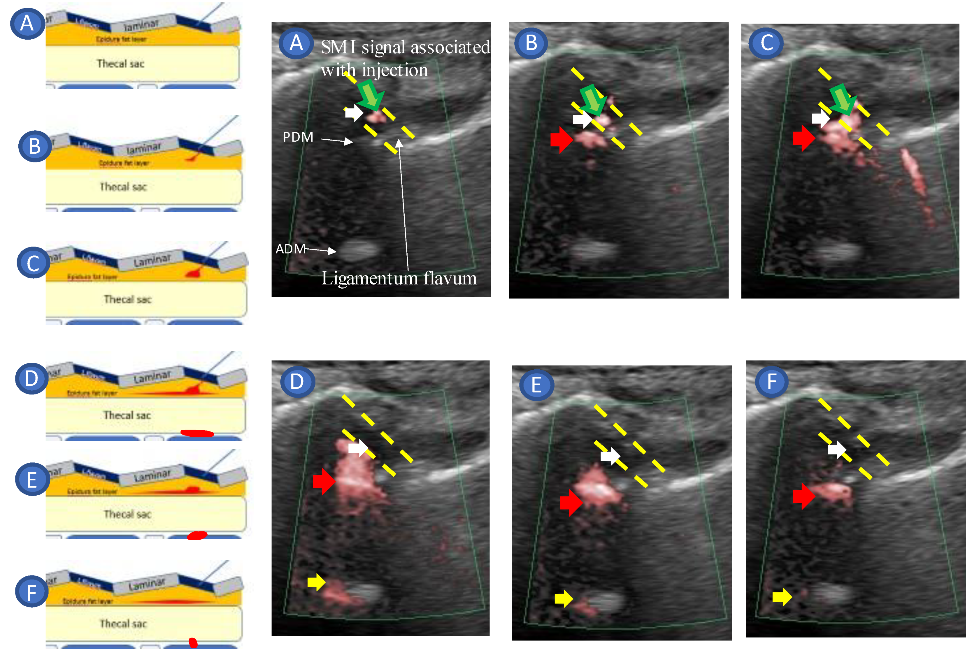
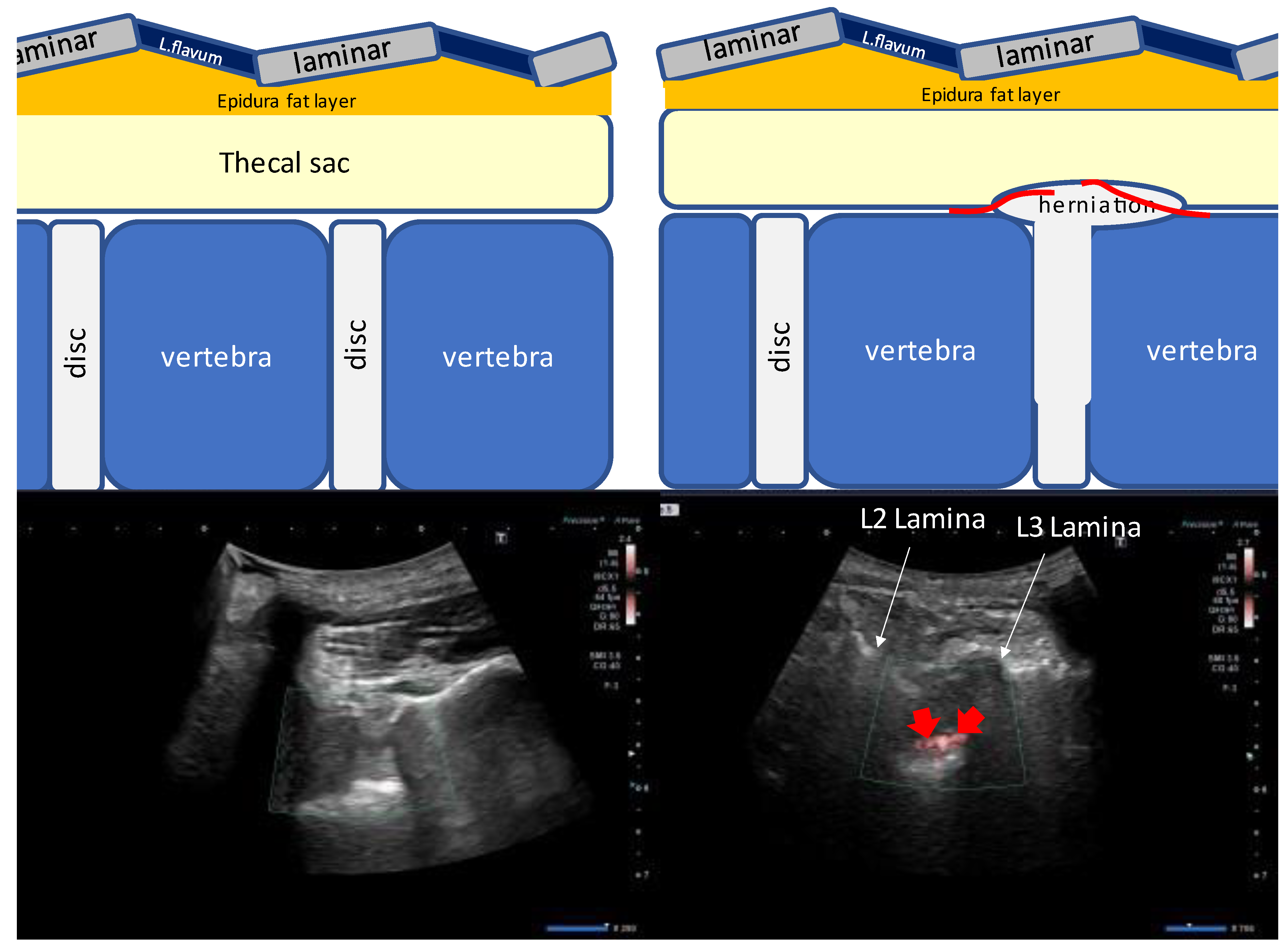
- Accurate needle tip guidance into the ligamentum flavum behind the epidural fat layer;
- Palpation of resistance by finger sense during ligamentum flavum insertion while confirming with sonography;
- Confirmation of the position of the needle tip in the ligamentum flavum;
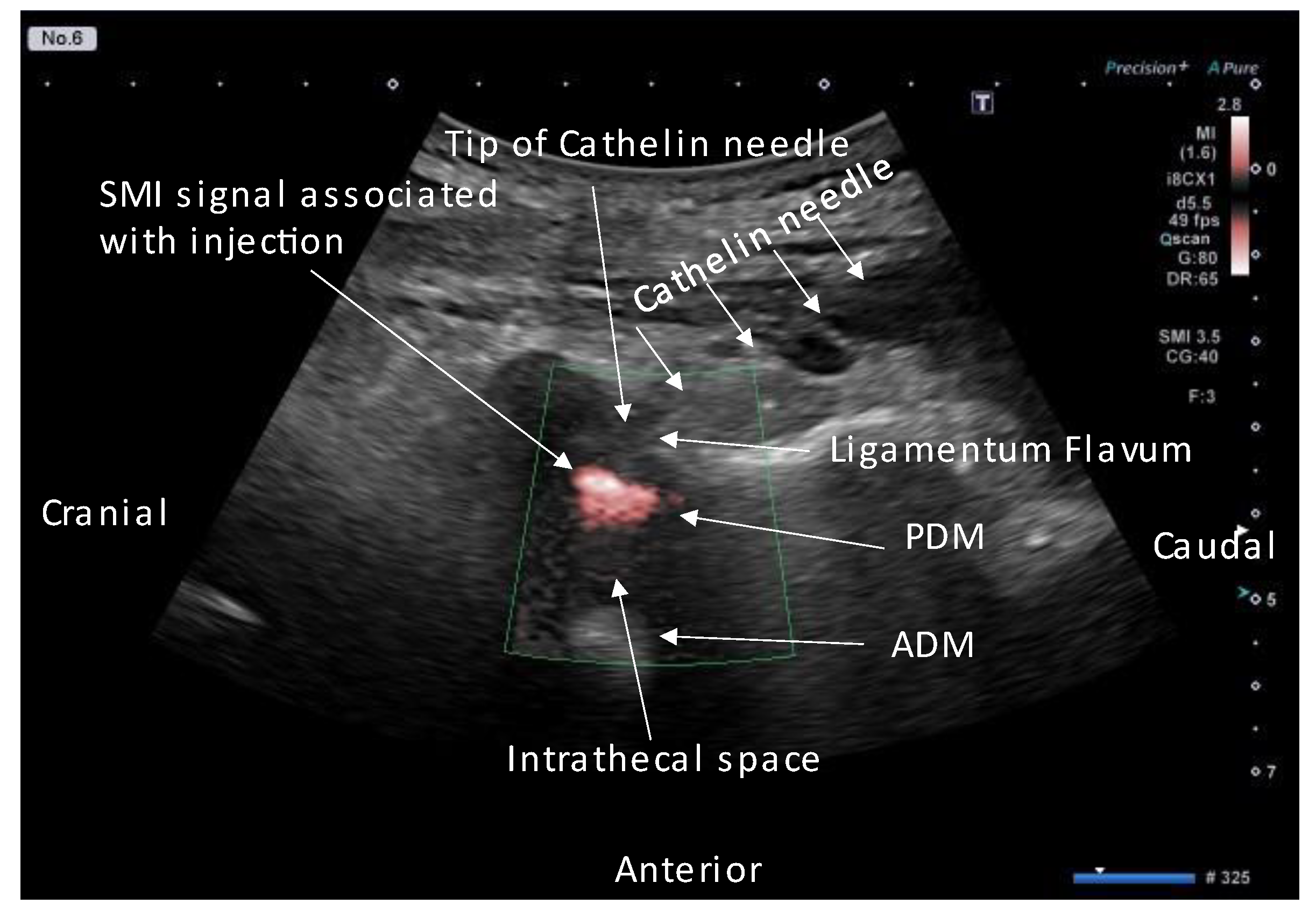
- Tracing the spread of the drug in the epidural space using SMI during the injection.
4.5. Real-Time Needle Guidance
4.6. Limitation
5. Conclusions
Supplementary Materials
Funding
Institutional Review Board Statement
Informed Consent Statement
Data Availability Statement
Conflicts of Interest
References
- Sicard, J.A.; Forestier, J. Methode radiographique d’exploration de la cavite epidurale par le Lipiodol. Rev. Neurol. 1921, 28, 1264–1266. [Google Scholar]
- Goodman, B.S.; Posecion, L.W.; Mallempati, S.; Bayazitoglu, M. Complications and pitfalls of lumbar interlaminar and transforaminal epidural injections. Curr. Rev. Musculoskelet. Med. 2008, 1, 212–222. [Google Scholar] [CrossRef] [Green Version]
- Stoll, A.; Sanchez, M. Epidural hematoma after epidural block: Implications for its use in pain management. Surg. Neurol. 2002, 57, 235–240. [Google Scholar] [CrossRef] [PubMed]
- Knezevic, N.N.; Paredes, S.; Cantillo, S.; Hamid, A.; Candido, K.D. Parasagittal approach of epidural steroid injection as a treatment for chronic low back pain: A systematic review and meta-analysis. Front. Pain Res. 2021, 2, 676730. [Google Scholar] [CrossRef] [PubMed]
- Grau, T.; Leipold, R.W.; Conradi, R.; Martin, E. Ultrasound control for presumed difficult epidural puncture. Acta Anaesthesiol. Scand. 2001, 45, 766–771. [Google Scholar] [CrossRef] [PubMed]
- John, H.; Sohn, K.; Kim, J.H. Relationship between needle depth for lumbar transforaminal epidural injection and patients’ height and weight using magnetic resonance imaging. Korean J. Pain 2022, 35, 345–352. [Google Scholar] [CrossRef]
- Kartal, S.; Kösem, B.; Kılınç, H.; Köşker, H.; Karabayırlı, S.; Çimen, N.K.; Demircioğlu, R.I. Comparison of Epidrum, Epi-Jet, and Loss of Resistance syringe techniques for identifying the epidural space in obstetric patients. Niger. J. Clin. Pract. 2017, 20, 992–997. [Google Scholar]
- Le Guen, M.; Charvet, A.; Leone, M.; Fischler, M. Epidrum is an unreliable device for identifying the thoracic epidural space. Eur. J. Anaesthesiol. 2018, 35, 716–717. [Google Scholar] [CrossRef]
- Elsharkawy, H.; Sonny, A.; Chin, K.J. Localization of epidural space: A review of available technologies. J. Anaesthesiol. Clin. Pharmacol. 2017, 33, 16–27. [Google Scholar] [CrossRef]
- Silbergleit, R.; Mehta, B.A.; Sanders, W.P.; Talati, S.J. Imaging-guided injection techniques with fluoroscopy and CT for spinal pain management. Radiographics 2001, 21, 927–939; discussion 940–942. [Google Scholar] [CrossRef] [Green Version]
- Rathmell, J.P.; Benzon, H.T.; Dreyfuss, P.; Huntoon, M.; Wallace, M.; Baker, R.; Riew, K.D.; Rosenquist, R.W.; Aprill, C.; Rost, N.S.; et al. Safeguards to prevent neurologic complications after epidural steroid injections: Consensus opinions from a multidisciplinary working group and national organizations. Anesthesiology 2015, 122, 974–984. [Google Scholar] [CrossRef] [Green Version]
- Husseini, J.S.; Simeone, F.J.; Staffa, S.J.; Palmer, W.E.; Chang, C.Y. Fluoroscopically guided lumbar spine interlaminar and transforaminal epidural injections: Inadvertent intravascular injection. Acta Radiol. 2020, 61, 1534–1540. [Google Scholar] [CrossRef] [PubMed]
- Shim, E.; Lee, J.W.; Lee, E.; Ahn, J.M.; Kang, Y.; Kang, H.S. Fluoroscopically guided epidural injections of the cervical and lumbar spine. Radiographics 2017, 37, 537–561. [Google Scholar] [CrossRef] [PubMed] [Green Version]
- Maeda, N.; Maeda, M.; Tanaka, Y. Direct visualization of cervical interlaminar epidural injections using sonography. Tomography 2022, 8, 1869–1880. [Google Scholar] [CrossRef]
- Maeda, M.; Maeda, N.; Masuda, K.; Nagano, T.; Tanaka, Y. Ultrasound-guided cervical intervertebral disc injection without fluoroscopy. J. Ultrasound Med. 2022, 42, 239–246. [Google Scholar] [CrossRef] [PubMed]
- Furness, G.; Reilly, M.P.; Kuchi, S. An evaluation of ultrasound imaging for identification of lumbar intervertebral level. Anaesthesia 2002, 57, 277–280. [Google Scholar] [CrossRef]
- Arzola, C.; Davies, S.; Rofaeel, A.; Carvalho, J.C. Ultrasound using the transverse approach to the lumbar spine provides reliable landmarks for labor epidurals. Anesth. Analg. 2007, 104, 1188–1192. [Google Scholar] [CrossRef] [Green Version]
- Grau, T.; Leipold, R.W.; Conradi, R.; Martin, E.; Motsch, J. Ultrasound imaging facilitates localization of the epidural space during combined spinal and epidural anesthesia. Reg. Anesth. Pain Med. 2001, 26, 64–67. [Google Scholar] [CrossRef]
- Grau, T.; Leipold, R.W.; Conradi, R.; Martin, E.; Motsch, J. Efficacy of ultrasound imaging in obstetric epidural anesthesia. J. Clin. Anesth. 2002, 14, 169–175. [Google Scholar] [CrossRef]
- McLeod, A.; Roche, A.; Fennelly, M. Case series: Ultrasonography may assist epidural insertion in scoliosis patients. Can. J. Anaesth. 2005, 52, 717–720. [Google Scholar] [CrossRef] [Green Version]
- Saba, L.; Saba, F.; Dagan, R.; De Filippo, M.; Marcy, P.Y. Technical efficacy and safety of CT-guided transforaminal periradicular infiltration using CT foot switches and MPR images. Acta Biomed. 2022, 92, e2021315. [Google Scholar] [PubMed]
- Kim, Y.J.; Kim, H.; Kim, H.J.; Koh, W.U.; Kim, J.; Ro, Y.J. Predicting epidural space spread using ultrasound color Doppler imaging in interlaminar epidural steroid injection: A prospective observational study. Pain Phys. 2022, 25, E349–E356. [Google Scholar]
- Lustig, J.P.; Aubry, S.; Vidal, C.; Pazart, L.; Moreau-Gaudry, A.; Bricault, I. Body interventional procedures: Which is the best method for CT guidance. Eur. Radiol. 2020, 30, 1593–1600. [Google Scholar] [CrossRef]
- Ha, S.O.; Kim, D.Y.; Sohn, Y.D. Clinical characteristics of adverse reactions to nonionic low osmolality contrast media in patients transferred from the CT room to the emergency room. SpringerPlus 2016, 5, 929. [Google Scholar] [CrossRef] [Green Version]
- Wylie, J.D.; Jenkins, P.A.; Beckmann, J.T.; Peters, C.L.; Aoki, S.K.; Maak, T.G. Computed tomography scans in patients with young adult hip pain carry a lifetime risk of malignancy. Arthroscopy 2018, 34, 155–163.e3. [Google Scholar] [CrossRef] [PubMed]
- Karmakar, M.K.; Li, X.; Ho, A.M.; Kwok, W.H.; Chui, P.T. Real-time ultrasound-guided paramedian epidural access: Evaluation of a novel in-plane technique. Br. J. Anaesth. 2009, 102, 845–854. [Google Scholar] [CrossRef] [Green Version]
- Lechner, T.J.; van Wijk, M.G.; Maas, A.J.; van Dorsten, F.R.; Drost, R.A.; Langenberg, C.J.; Teunissen, L.J.; Cornelissen, P.H.; van Niekerk, J. Clinical results with the acoustic puncture assist device, a new acoustic device to identify the epidural space. Anesth. Analg. 2003, 96, 1183–1187. [Google Scholar] [CrossRef] [PubMed]
- Miyabe, M. Genesis of “negative pressure” during hanging drop; the answer is positive pressure. J. Anesth. 2022, 36, 441–443. [Google Scholar] [CrossRef]


Disclaimer/Publisher’s Note: The statements, opinions and data contained in all publications are solely those of the individual author(s) and contributor(s) and not of MDPI and/or the editor(s). MDPI and/or the editor(s) disclaim responsibility for any injury to people or property resulting from any ideas, methods, instructions or products referred to in the content. |
© 2023 by the authors. Licensee MDPI, Basel, Switzerland. This article is an open access article distributed under the terms and conditions of the Creative Commons Attribution (CC BY) license (https://creativecommons.org/licenses/by/4.0/).
Share and Cite
Maeda, M.; Maeda, N.; Masuda, K.; Kamatani, Y.; Takamasa, S.; Tanaka, Y. Ligamentum Flavum Rupture by Epidural Injection Using Ultrasound with SMI Method. Tomography 2023, 9, 285-298. https://doi.org/10.3390/tomography9010023
Maeda M, Maeda N, Masuda K, Kamatani Y, Takamasa S, Tanaka Y. Ligamentum Flavum Rupture by Epidural Injection Using Ultrasound with SMI Method. Tomography. 2023; 9(1):285-298. https://doi.org/10.3390/tomography9010023
Chicago/Turabian StyleMaeda, Manabu, Nana Maeda, Keisuke Masuda, Yoshiyuki Kamatani, Shimizu Takamasa, and Yasuhito Tanaka. 2023. "Ligamentum Flavum Rupture by Epidural Injection Using Ultrasound with SMI Method" Tomography 9, no. 1: 285-298. https://doi.org/10.3390/tomography9010023