Article

Microfactory Design for Valorization of E-Waste Plastics (Acrylonitrile-Butadiene-Styrene, Polycarbonate, and Polypropylene) on Additive Manufacturing Sector

by
Alejandro Moure Abelenda
* and
Farid Aiouache
*
School of Engineering, Lancaster University, Lancaster LA1 4YW, UK
*
Authors to whom correspondence should be addressed.
Recycling 2023, 8(3), 46; https://doi.org/10.3390/recycling8030046
Submission received: 29 March 2023 / Revised: 18 April 2023 / Accepted: 28 April 2023 / Published: 1 May 2023
(This article belongs to the Special Issue Advances in the Recycling, Processing and Use of Plastic Waste II)

Abstract

:
Less than half of e-waste plastics are sorted worldwide, and this rate is likely to decline as major processing countries have banned importation of e-waste plastics. This forces the development of decentralized processing facilities, also known as microfactories. The present work investigates the recyclability of different grades of acrylonitrile-butadiene-styrene (ABS) copolymer, polycarbonate, and polypropylene, which were found to be very abundant in a recycling site in the UK. The determination of the matrix relied on the resin identification codes imprinted in the e-waste plastics and subsequent Fourier-transform infrared spectroscopy (FTIR). Melt-blend extrusion technology enabled the valorization of the wasted thermoplastics as 3D filament without significant degradation of the polymers. The recycled materials maintained the tensile strength at around 2.5 MPa in agreement with the specifications offered by virgin polymers. Further characterization was done by means of laser microscope, thermogravimetric analysis, and X-ray fluorescence to determine the commercial viability of the recycled filament. A modified solvent-based method was developed with acetone to remove the brominated flame retardants: 25 g/100 mL, 30 min of contact time, and 4 extraction steps. The FTIR results show that the degradation of the rubbery dispersed phase corresponding to the butadiene can be accumulated in the less soluble fraction of the extracted ABS.

1. Introduction

The fate of e-wastes is a growing concern of approximately 54 million tonnes per annum worldwide [1], which is estimated to double by 2050 [2]. The valorization of these materials is worth $64 billion but less than half of e-waste plastics are recycled globally [3,4]. The Basel Convention on the control of transboundary movements of hazardous wastes limits cooperation between countries to handle e-waste [5]. Furthermore, the rate is likely to decline as major processing countries are progressively banning importation of plastic wastes [6]. Therefore, since the modest global recycling efforts underway are crushing, there is a need for decentralized and highly specialized plastic recycling sites (also known as microfactories) that additionally reduce the transport costs [1,4]. E-waste plastics occupy a large amount of space on the premises of recycling companies, and the process of identification and sorting is challenging, owing to the wide range of polymer mixtures that are used to get the desired properties [7]. The decentralized model of plastic recycling can be expanded to the prosumer level due to the proliferation of recyclebots (i.e., domestic melt-blend extruders suitable for processing plastic waste) [8]. The rise of prosumers and do-it-yourself activities creates a broader profile of clients that want to purchase an equipment of sophisticated recycling technology with specifications that range between domestic operation and an industrial use [9]. Mikula et al. [8] discussed the route of using a recyclebot for manufacturing of 3D printing filament as a second life for waste plastics. They offered a review of the different type of desktop filament extruders, exposing the much higher price of the compounder commercialized by the Dutch company 3devo B. V. [10]. The higher prize of this equipment (on average almost 4 times higher than the other recyclebots available in the market [8]) does not appear to be justified by the compounding parameters: filament diameter variability, the extrusion speed, and the accessibility to a grinder. Nevertheless, it is important to highlight the access to customer support, quality control procedures, instructions to operate the equipment with a range of plastics, tolerance to impurities, and the DevoVisio software (Beta version) [11] which allows the continuous monitoring of the performance of the melt-blend extruder. Of particular importance is the ability to measure the diameter of the filament being produced with the optical sensor and other mechanical designs that prevent the clogging of the equipment when processing a generous variety of plastics. It is difficult to assess the reason for the superior performance of the 3devo equipment (€5350; [8,12]) because the access to the intellectual property is limited, due to the lack of an Open Source License, unlike with the recyclebot designed by Woern et al. [13], which costs $671. According to Woern et al. [13], the manufacturing of 3D filament with their recyclebot using waste plastics is 22% cheaper than that using the commercial polymer pellets, and even costs a thousand times lower ($0.025/kg) than the 3D filament available in the market. The relative affordability of some of these pieces of equipment to domestic users offers the possibility of reducing, by 80%, the cost of replicating components with recycled materials, since the expenses of the 3D printing are mainly derived from the prize of the filament [8].
Mikula et al. [8] described some of the stages to produce recycled 3D printing materials: selection and collection of the waste, grinding, melt-blend extrusion, and printing of the desired components. Some key stages that are often overlooked when designing the recycling process are the washing and sanitation of the plastics [14], which directly affect the specifications of the 3D filament: tensile testing, aesthetic appearance, and diameter. Boz Noyan et al. [14] characterized the plastic waste after sorting (including magnetic separation), after washing, and after melt-compounding for injection molding. Unlike the 3D printing that is more versatile and able to easily adapt and produce a practically unlimited range of specimen shapes, the injection molding is more suitable for production of specific components in large quantities. Importantly, both routes share the steps of washing and compounding. Boz Noyan et al. [14] found that washing under severe conditions significantly reduced thermos-oxidative stability, molecular weight, and melt viscosity. The industrial washing that was applied to the packaging waste at a large-scale recycling plant in Norway lasted for 30 min and included prewashing at room temperature, wet grinding, friction washing with NaOH and defoamer at 70–80 °C, rinsing at room temperature, centrifuging, dewatering, and thermal drying. An important parameter to consider for the compounding step is the length of the screw, as this will ensure enough mixing between the different polymers, compatibilizers, and additives. Boz Noyan et al. [14] analyzed different screw configurations considering the presence of different mixing elements per screw shaft, which enhanced the combination of polymers without affecting the speed of extrusion. They found that compounding parameters and screw configuration did not influence the stiffness of unwashed and washed recycled materials. However, they found that the elongation-at-break was dependent on the temperature of the melt-extrusion. In addition to the mechanical characterization of the recycled materials, the thermal stability is also determined in order to understand the level of degradation and the feasibility of applying several cycles that would give the plastics different uses [8,14].
The primary or secondary recycling capabilities using mechanical separation by reading the Resin Identification Code (RIC), which is indented in the e-waste plastics [7,9], avoid the loss of functionalities of the polymers; hence these technologies are preferred to other types of upgradation methods. In this way, the recycled materials can be used for the same or similar purposes as the original product [4]. Although tertiary and quaternary recyclings are less cost-effective, these technologies are applied to deal with complex mixtures of polymers when mechanical separation is not sufficient [15]. However, a combination of these technologies (i.e., tertiary chemical treatment with quaternary energy production) can be used to improve, techno-economically, the performance of the downstream process. For example, removal of brominated flame retardants (BFR) by solvent extraction is used to enhance the thermal decomposition and mass loss in a subsequent pyrolytic step [15,16]. It should be noted that some types of BFR can be in concentrations of up to 30% by weight, which means that 1 kg of polymer would contain 50–300 g of flame retardant [17]. On the other hand, the solvent extraction of BFRs might not be convenient for optimizing the downstream processing of primary or secondary mechanically separated polymers. For example, in the manufacturing of different plastic components of the casing of electrical devices, the melt-blend extrusion is carried out at temperatures slightly greater than the melting point. Since the effect of flame retardants can be noticeable even at temperatures closed to the glass transition, the presence of these additives might avoid the mass loss of the polymer that is being extruded and, importantly, the emission of pollutants of the ABS [18].
With these notions in mind, the design of a microfactory for recycling acrylonitrile-butadiene-styrene copolymer (ABS), polycarbonate (PC), and polypropylene (PP) was investigated in the present article with the 3devo recyclebot, because these types of e-waste plastics were found to be very abundant in a recycling site in the UK. ABS and PC are the main components in telephone handsets, keyboards, monitors, and computer housing, while PP is widely employed for the manufacturing of boxes and casings. Other polymers also vastly reported in the literature as part of e-waste plastics, such as polystyrene and polyvinyl chloride [1,19,20], were found in lower quantities and their recyclability was not investigated. The research objectives that helped to elucidate the best route for the valorization of the e-waste plastics were: (a) to find out synergistic approaches to combining these materials, (b) to define the specifications of the equipment required for the processing, and (c) to identify the best component that can be replicated. In this way, the novelty of the present work relies on investigating the techno-economic feasibility of scaling up a desktop recycling process and improving the logistics to enable the smooth operation of a microfactory. Given the open-source license of recyclebots and their versatility [9,13], this type of equipment was considered suitable for the design of a valorization process and the scaleup to modest real conditions of the rate of handling e-waste plastics by medium-size recycling enterprises (~300 tonnes per annum). In this way, following the instructions of the manufacturer of the melt-blend extruder [10,21,22,23], virgin polymers were employed to initiate the melt-blend extrusion process, and the share of the fresh materials was progressively decreased until the point of operating the equipment with 100% e-waste plastic. Unlike the selection of the grades of the virgin material, which was based on its melt-flow index (MFI), the different grades of the waste ABS were identified by the flow regime in the extruder and the color of the waste ABS (i.e., white or black). The valorization of the thermoplastics as 3D filaments for additive manufacturing was subsequently confirmed by printing a specimen, in agreement with the methodology of Arostegui et al. [24], to increase the technology readiness level.

2. Results

The following subsections include the data that support the design of a microfactory for processing ABS, PC, and PP. It is important to mention that the PC was only found in large quantities in the recycling site when this polymer was associated with the ABS (i.e., ABS + PC) and for this reason the recycling of PC alone was not investigated.

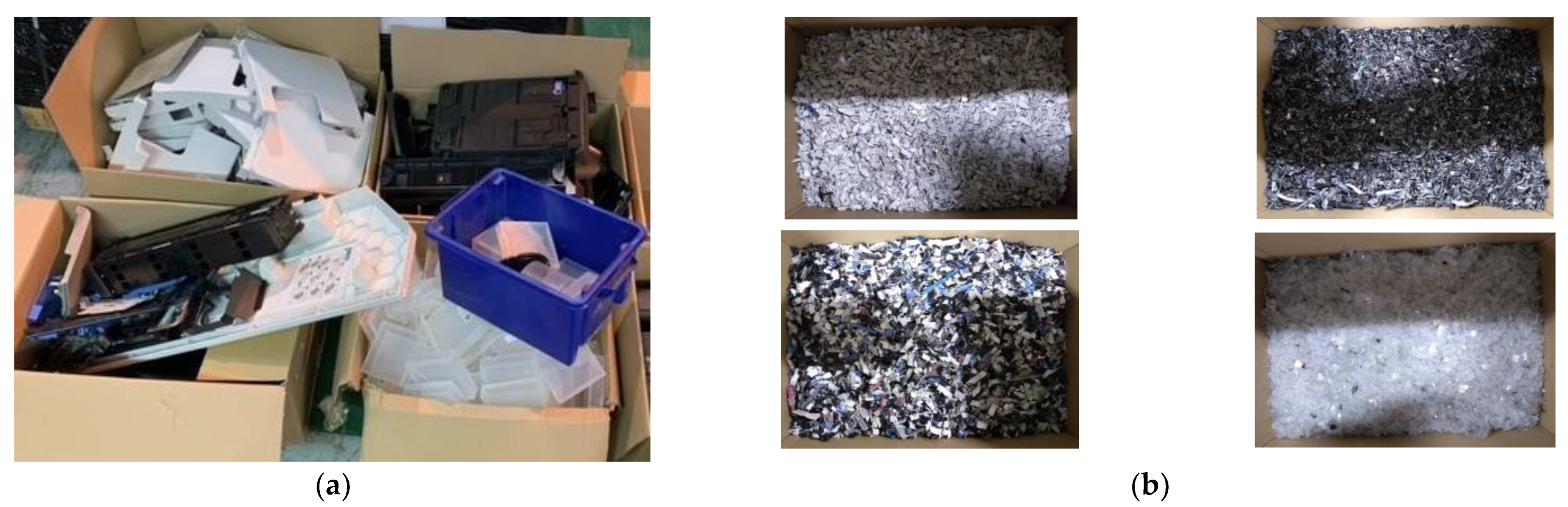
2.1. Collection of the Waste and Shredding

The bulkiest e-waste plastics were identified in a recycling company (Figure 1a) and subsequently shredded to less than 5 mm (Figure 1b). As can be appreciated in Figure 1, the sample of ABS + PC was more heterogenous than the other samples: white ABS, black ABS, and PP. Thereby, one could expect a low adhesion of the particles of ABS + PC during the extrusion process and the need of using a compatibilizer or impact modifier to improve the tension strength of the 3D filament produced with this e-waste plastic [19]. According to Ramesh et al. [25], PC offers greater mechanical performance and is less susceptible to degradation than ABS. On the other hand, ABS is more fluid and its shear thinning behavior is a major reason for improving processability of PC. The compatibility or miscibility of PC and ABS depends on the grade of the ABS and the content of the acrylonitrile monomer [25]. Since only the ABS + PC type of material was considered for the present investigation, the use of compatibilizers and impact modifiers was avoided, because the primary recycling strategy that was followed maximized the preservation of the additives already present in the e-waste plastics, except for the BFR.

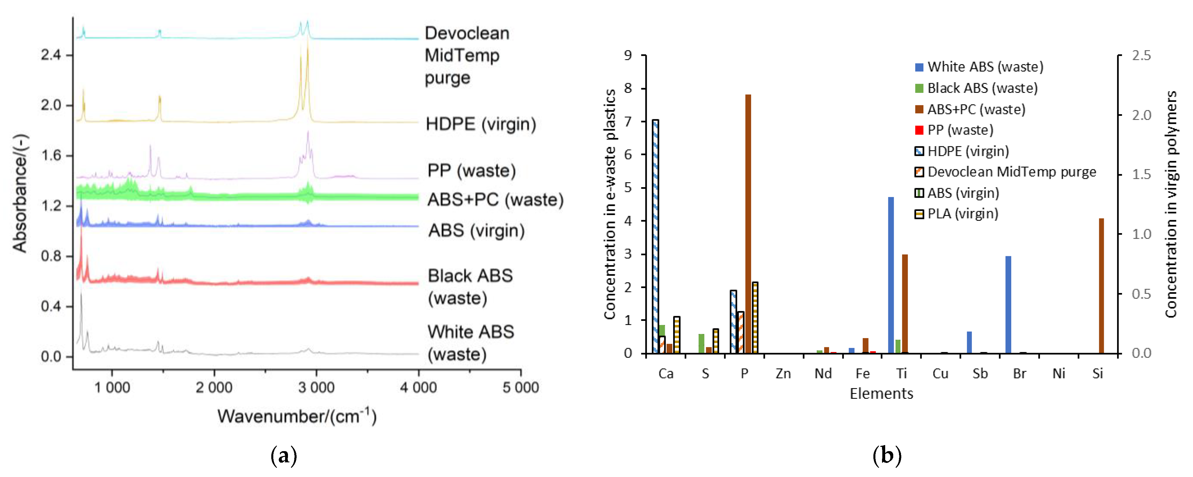
2.2. Characterization of the Matrix and the Additives of the E-Waste Plastics

In addition to the RIC, the difference between the matrices of the e-waste plastics was confirmed with Fourier-transform infrared spectroscopy (FTIR) and X-ray fluorescence (XRF) analysis (Figure 2). Figure 2 shows the FTIR and XRF profiles of the e-waste plastics (white ABS, black ABS, ABS + PC, and PP), the virgin polymers employed to assist the melt-blend extrusion (ABS, high-density polyethylene (HDPE), and polylactic acid (PLA)), and the purge material recommended for the cleaning of the equipment after the operation (i.e., Devoclean MidTemp purge). The most characteristic peak that was identified for the ABS was found at the 2200 cm−1 (Figure 2a), corresponding to the nitrile group [24]. It is noteworthy to mention that up to 10 replicates were considered for the samples which were found to be more heterogenous (i.e., with different colors). In this way, the larger error band found for the ABS + PC in Figure 2a is associated with the greater variability of the matrix of this sample type. With regard to the initial characterization of the samples in terms of XRF (Figure 2b), calcium, sulfur, and phosphorus were found to be the most abundant trace elements in all the samples, but it is also important to highlight the presence of BFR in the sample of white ABS.

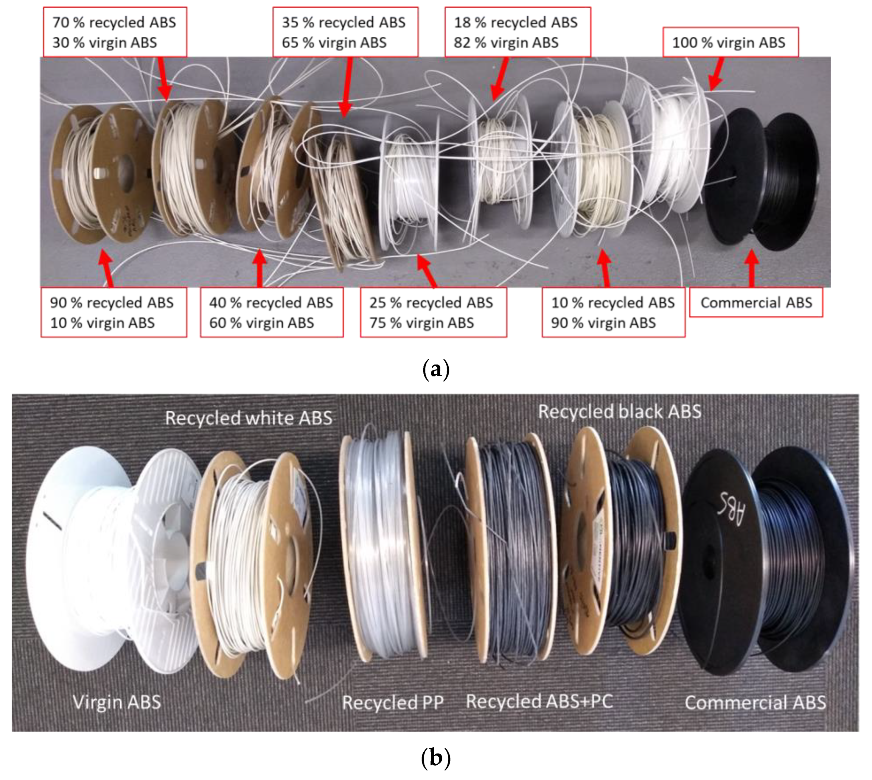
2.3. Melt-Blend Extrusion

The melt-blend extrusion process was performed following the advice provided by the manufacturer of the 3devo compounder: starting with virgin materials and progressively increasing the share of waste. This can be seen in Figure 3a for the white ABS. It was necessary to use the HDPE and the PLA as transition polymers for the ABS and the PP, respectively, in order to obtain the 3D filament with 100% recycled material (Figure 3b).

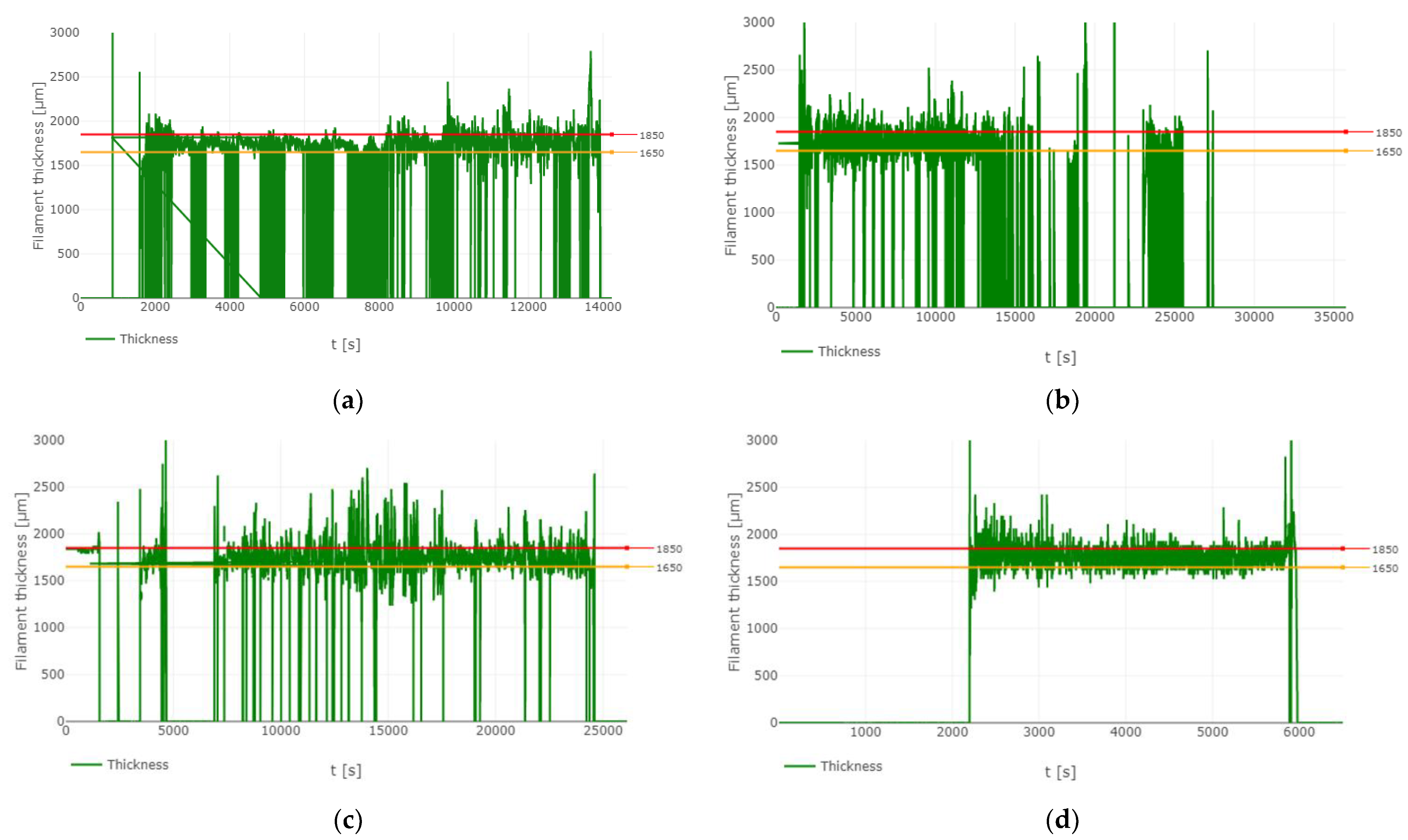
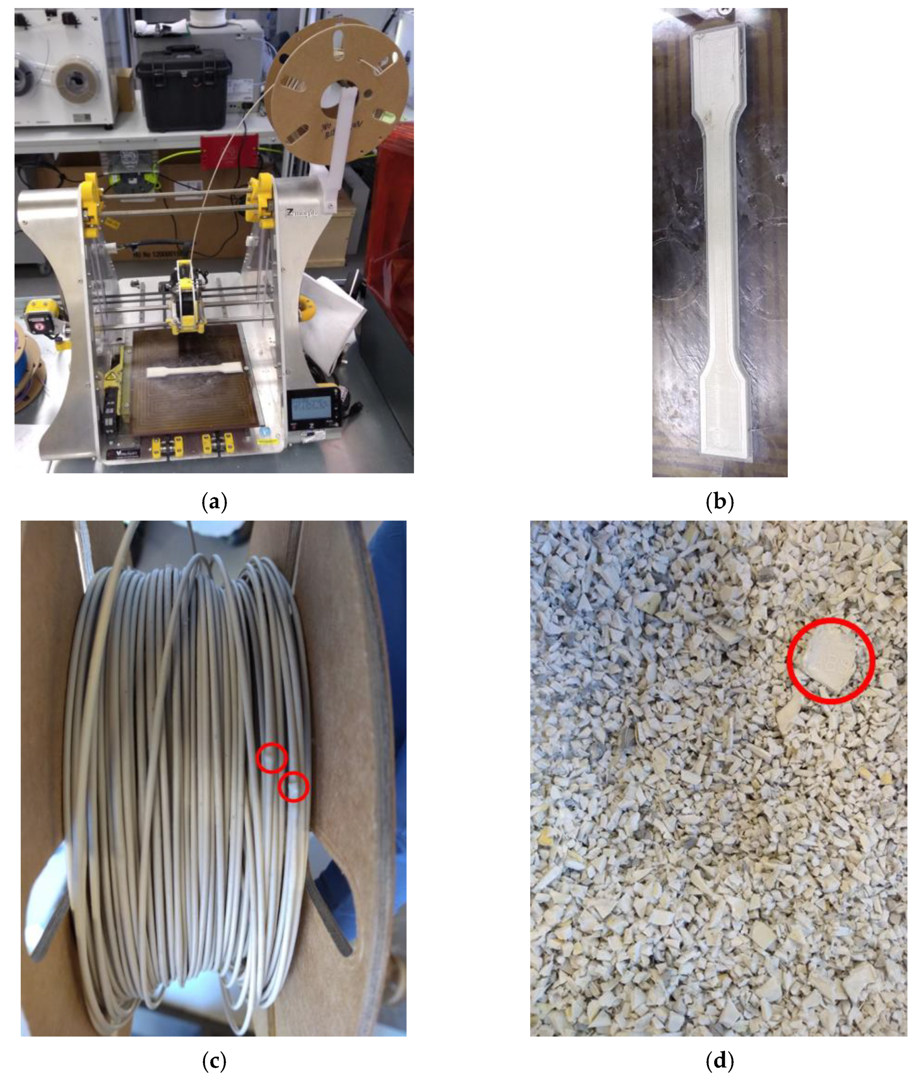
2.4. 3D filament Diameter

The filament thickness monitored with the optical sensor of the 3devo compounder during the recycling of the waste ABS, PC, and PP is shown in Figure 4. Additionally, a quality check was performed with PLA, following the recommendations of the manufacturer of the recyclebot [26], to confirm that the equipment was operating properly and the fluctuations observed were derived from the nature of the complex e-waste plastic. The white ABS was found to be the most suitable material to be valorized as 3D filament via melt-blend extrusion, as it was easier to get the filament diameter in the range of 1.75 ± 0.10 mm (<8000 s in Figure 4a). The black ABS was more susceptible to clog the recyclebot and it was necessary (>8000 s in Figure 4a) to repeat the preparation of the 3D filament for this matter (>15000 s in Figure 4b). Similarly, the recycling with the ABS + PC (<15000 s in Figure 4b) and PP (Figure 4c) was challenging, due to difficulties maintaining a constant diameter of the 3D filament. The quality check with PLA (Figure 4d) informed on the difficulty of continuously measuring the filament thickness with the waste polymers. The diameter thickness went to zero multiple times during the operation of the compounder with white ABS, black ABS, ABS + PC, and PP (Figure 4) because the filaments were dancing and going out of the optical sensor.

2.5. 3D Printing

The feasibility of 3D printing with the recycled filament was tested (Figure 5a) to prepare dumbbell-shaped specimens (Figure 5b), according to the British Standard EN ISO 527-2:2012 (test conditions for molding and extrusion), and to characterize the performance of the recycled material in the mechanical testing. A limited number of dog-bone specimens could be prepared due to the presence of lumps in the filament that clogged the 3D printer (Figure 5c). This was associated with the poor shredding of the samples (presence of 2-cm particles) and the unmelted particles leading to lumps of a diameter much greater than 1.75 mm, which were also a consequence of the very short screw of the melt-blend-extruder, which did not promote the complete mixing of the samples of e-waste.

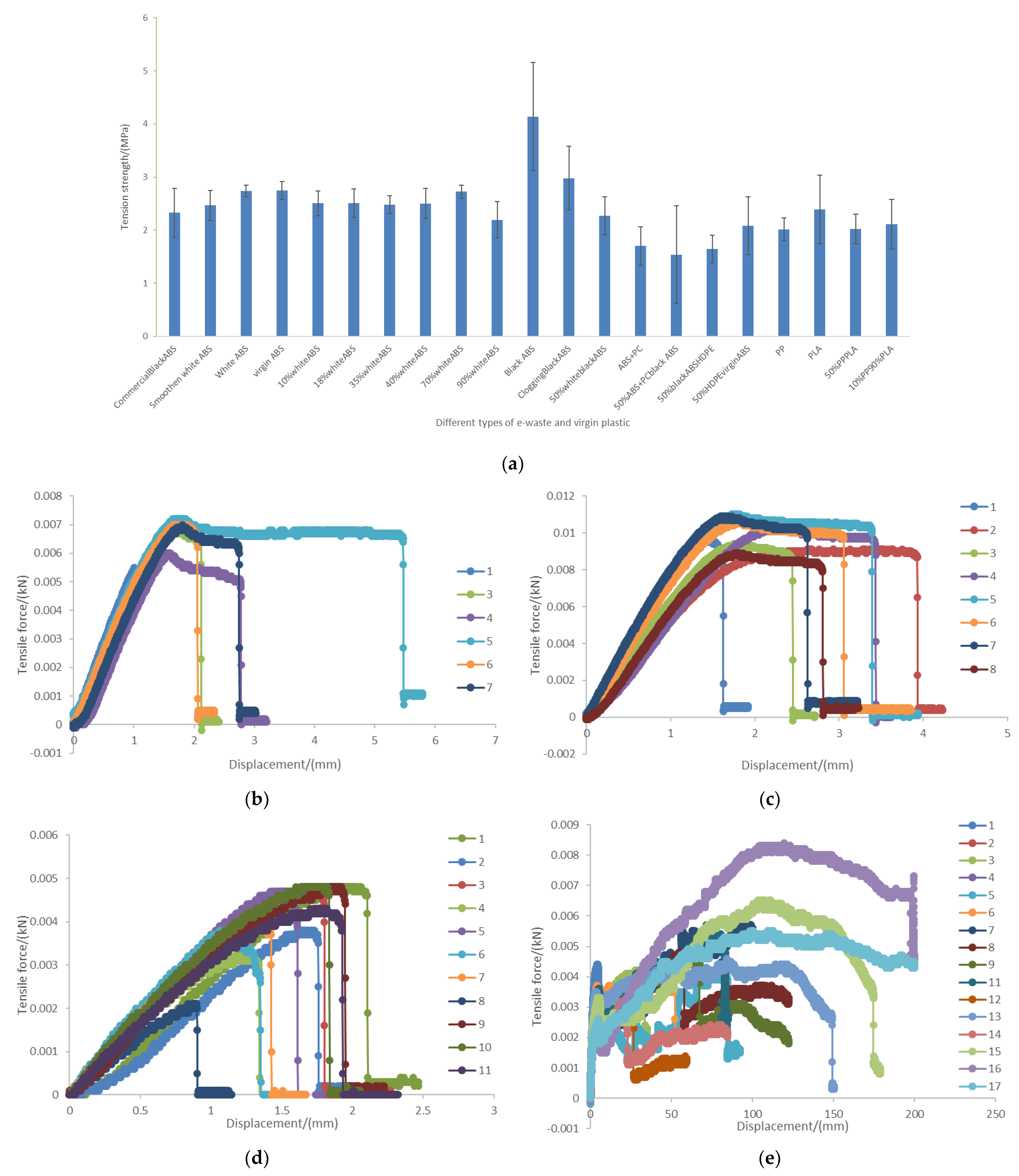
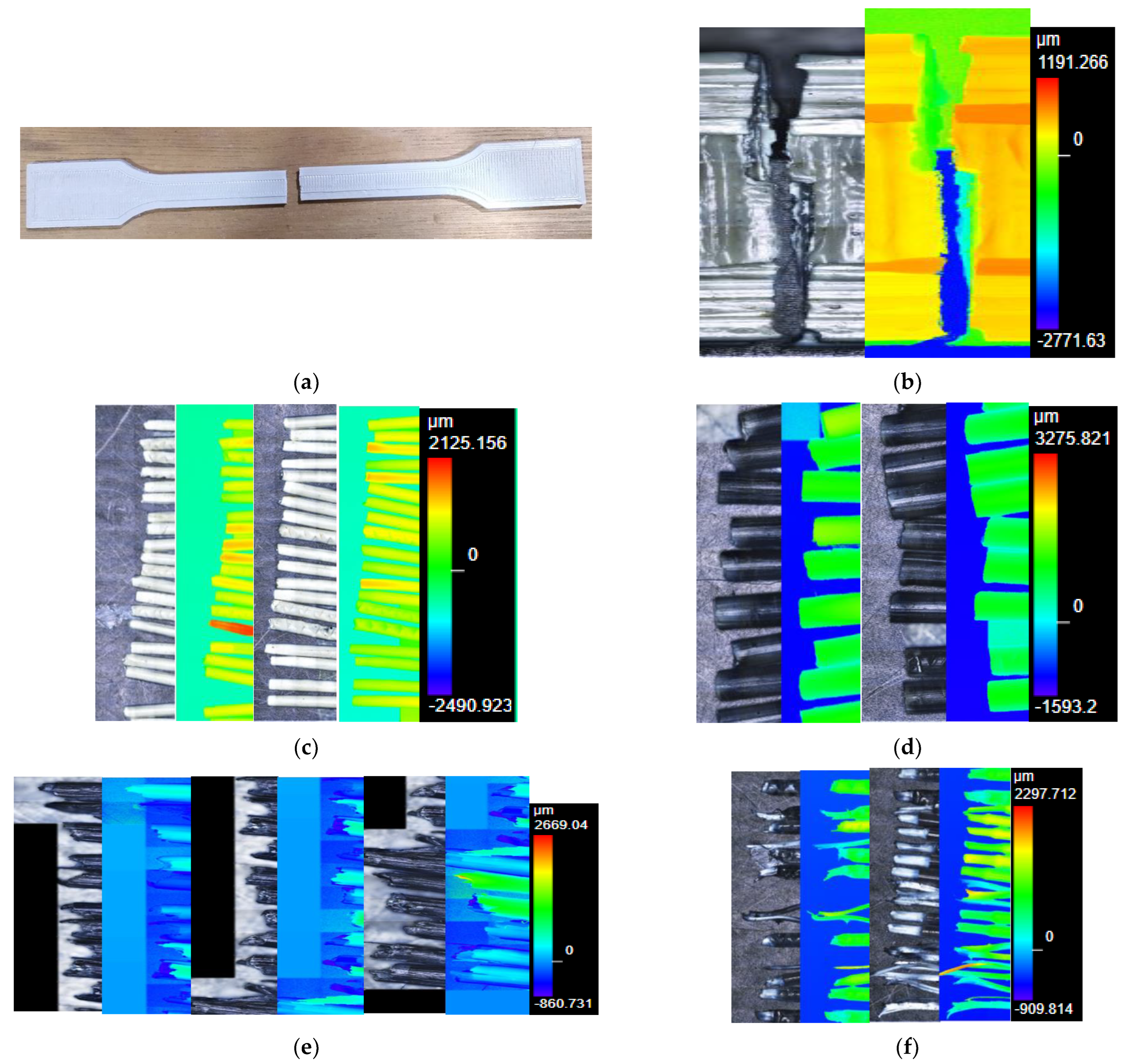
2.6. Tensile Testing

The recycled materials had an average tensile strength around 2.5 MPa and the greatest tensile strength was found for the black ABS (4.14 ± 0.34 MPa) while the lowest corresponded to the ABS + PC (1.70 ± 0.36 MPa). The blend of the waste materials with the virgin polymers did not offer a greater tensile strength compared to the 3D filament produced with 100% recycled material. It is important to highlight that the tensile strength reported in Figure 6a refers to the maximum force that the material can hold before starting the neck formation. Figure S1 shows the neck formation in the PP. It is noteworthy to mention that for the calculation of the tensile strength, a homogeneous diameter of 1.75 mm was assumed for all filaments. This implied that the cross-sectional area considered for the filament (2.41 mm2) was approximately 10 times smaller than that for the dumbbell-shaped specimen (40 mm2; [27]). Nevertheless, the tension strength measure for the dog-bone specimen of white ABS (1.54 MPa) was in the same order of magnitude because the maximum force reached was also approximately 10 times greater (0.0617 kN; Figure S2) than what was achieved with the filament of white ABS (Figure 6b). These results were an order of magnitude lower than those reported by Zhang et al. [28], who used virgin HDPE to support the recycling of the waste HDPE. Similarly, Boz Noyan et al. [14] found 15 MPa of tensile strength regardless of whether the severe washing conditions had been applied to plastic waste before the melt-blend extrusion. In the present study, the HDPE did not enhance the tensile strength of the ABS filament as there was a weak interaction between these polymers. This could be seen in the loose threads upon rupture of the filaments of HDPE and ABS in the tensile testing (Figure S3). Figure 6c–e show the profiles of the tensile force versus the displacement for the black ABS, ABS + PC, and PP. The profiles of the tensile force versus extension corresponding to the remaining combination of polymers are shown in Figures S4–S7.
According to the empirical results, the neck formation can be seen with less than 2 mm of elongation of the filament. In the case of the white and black ABS, the elongation before failure was not found beyond 6 mm (Figure 6b,c). As the filament of ABS + PC was brittle due to the heterogeneity nature of the sample (Figure 1), there was no neck formation, and minimum elongation took place before the breakage of the filament specimens (Figure 6d). The maximum displacement that was allowed for the tensile testing was 200 mm, but this was not enough for some of the filament specimens of PP, as this material was found to be very flexible without breaking even at 200 mm of deformation (Figure 6e). This means that the elongation-at-break of the PP filament would be greater than 2000%, which is a value much higher than the maximum 375% of elongation reported by Boz Noyan et al. [14] for the specimen prepared with molding injection. The melt-blend extrusion process did not negatively affect the degradability of the e-waste plastics, as several changes in the conformation of the matrix polymers could be identified in the raw samples and in the recycled filaments, including the glass transition temperature, crystallization temperature, and melting point (Figures S8–S12). Although similar weight losses were found in the samples of plastic before and after the melt-blend extrusion, in general (except for the black ABS; Figure S9) it could be considered that the extruded samples were more recalcitrant as the number of endothermic degradation reactions increased [29], particularly at high temperatures (above 400 °C). As can be seen in Figure S13, conducting the coupled thermogravimetric analysis (TGA) and differential scanning calorimetry (DSC) at temperature up to 800 °C affected the behavior of the recycled white ABS filament and the commercial black ABS, increasing in both cases the proliferation of endothermic reactions both at the beginning and towards the end of the analysis.
The impact of the storage conditions on the behavior of the polymers was also assessed with the TGA/DSC. The storage of the HDPE at room conditions made this material more recalcitrant and hindered its processability with the melt-blend extrusion (Figure S14). The other material that the manufacturer of the compounder allowed to be left in the shutdown equipment was the PLA, and its comparison with the HDPE is also shown in Figure S14. Figure S14 confirms that the Devoclean MidTemp purge recommended by the manufacturer was also polyethylene. The similarities between the HDPE and the Devoclean MidTemp purge can be seen in the comparison of the FTIR spectra offered in Figure 2 and Figure S15.

2.7. Aesthetic Properties

The performance of the recycled filament was also characterized with the laser microscope using 5 times (×5), 10 times (×10), and 20 times (×20) magnifications. This equipment was used to create a 3D model of the specimens, which were prepared with the blends of polymers: the color scales in Figure 7 and the Supplementary Materials represent the depth of the laser microscope images. In the broken dumbbell-shaped specimen (Figure 7a), many fibers can be appreciated due to the way this component was manufactured with the 3D printer (Figure 7b). It is expected that if the dog-bone specimen was prepared via molding injection, a cleaner rupture would have been obtained. In fact, the rupture of filaments made with the white ABS (Figure 7c) and the black ABS (Figure 7d) was clean with minimum neck formation. The same behavior was observed for a commercial filament of black ABS (Figure S16). However, when the black ABS and the white ABS were combined, the resulting filament was more flexible and allowed neck formation (Figure S17). Figure S17 shows the failure of the filament prepared with a blend of 50% white ABS and 50% black ABS. The supplementary material contains more laser microscope images of the filaments of a progressive increase in the share of white ABS, in relation to virgin ABS, at the point of rupture (Figures S18–S21, S23, S25 and S27) and their neck formation (Figures S22, S24 and S26). Figure S28 shows the failure of the filament prepared with virgin ABS. Figure S29 shows the rupture of the filament prepared with a blend of 50% HDPE and 50% black ABS. Figure S30 shows the neck formation in the filament prepared with a blend of 50% HDPE and 50% black ABS. Although the combination of black ABS with HDPE provided similar results to that of ABS + PC, in terms of tensile strength (Figure 6a), the aesthetic behavior upon failure was different. Figures S29 and S30 justify that the interaction between the black ABS and the HDPE was greater than the compatibility of the ABS + PC (Figure 7e). As can be seen in Figure 7e, the tenacity of the ABS + PC was lower than that of the black ABS + HDPE because the former did not have significant neck formation before the rupture. The brittleness of the filament ABS + PC can also be appreciated on the many fibers that can be seen in the broken specimens (Figure 7e). A closer look at the striations of the ABS + PC can be seen in Figure S31. Microscope images have been traditionally used to assess the compatibilization of ABS and PC [30,31]. The primary recycling of the ABS + PC, preventing the loss of additives, was not enough to enhance the interaction between the polymers of this e-waste plastic. As described by Pelto et al. [32], the use of a suitable compatibilizer is required at a rate of 5 wt.% to increase the share of poly(styrene-acrylonitrile), also known as SAN copolymer. Additionally, as described by Ramesh et al. [25], an impact modifier, such as ethylene-methyl acrylate-glycidyl methacrylate, can be included in the formulation of the recycled ABS + PC because this terpolymer would further increase the miscibility with the PC and SAN copolymer by dissolving both phases.
The greatest flexibility was obtained with the filaments of PP; thus, its behavior was mainly characterized by the reduction of the cross-sectional area to enable the extension and avoid the failure under a traction force (Figure 7f). Additionally, Figure S32 displays a filament of PP that showed fibrous behavior upon rupture in the tensile testing. It is important to clarify that the filament of PP was transparent and the black part in the microscope pictures was the color of the base of the sample holder (Figure 7f). In Figure 7f the white part of the filament resulted from stretching of the material and neck formation. Even the addition of PLA in shares of 50% (Figure S33) and 90% (Figures S34 and S35) did not reduce the transmittance of the material. The ratio of PLA to PP, however, affected the fibrous behavior, as more fibers were observed when both materials were combined at approximately the same rate because this enhanced the incompatibility between the 2 polymer types (Figure S33). These fibers were not originally present in the filament of PLA (Figures S36 and S37).

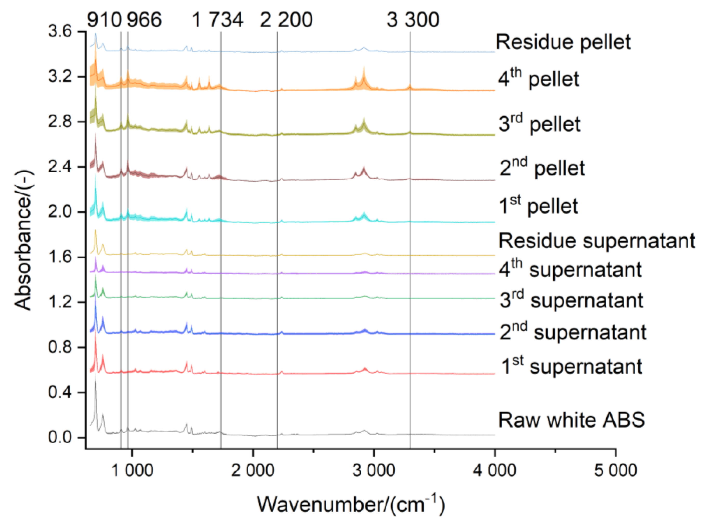
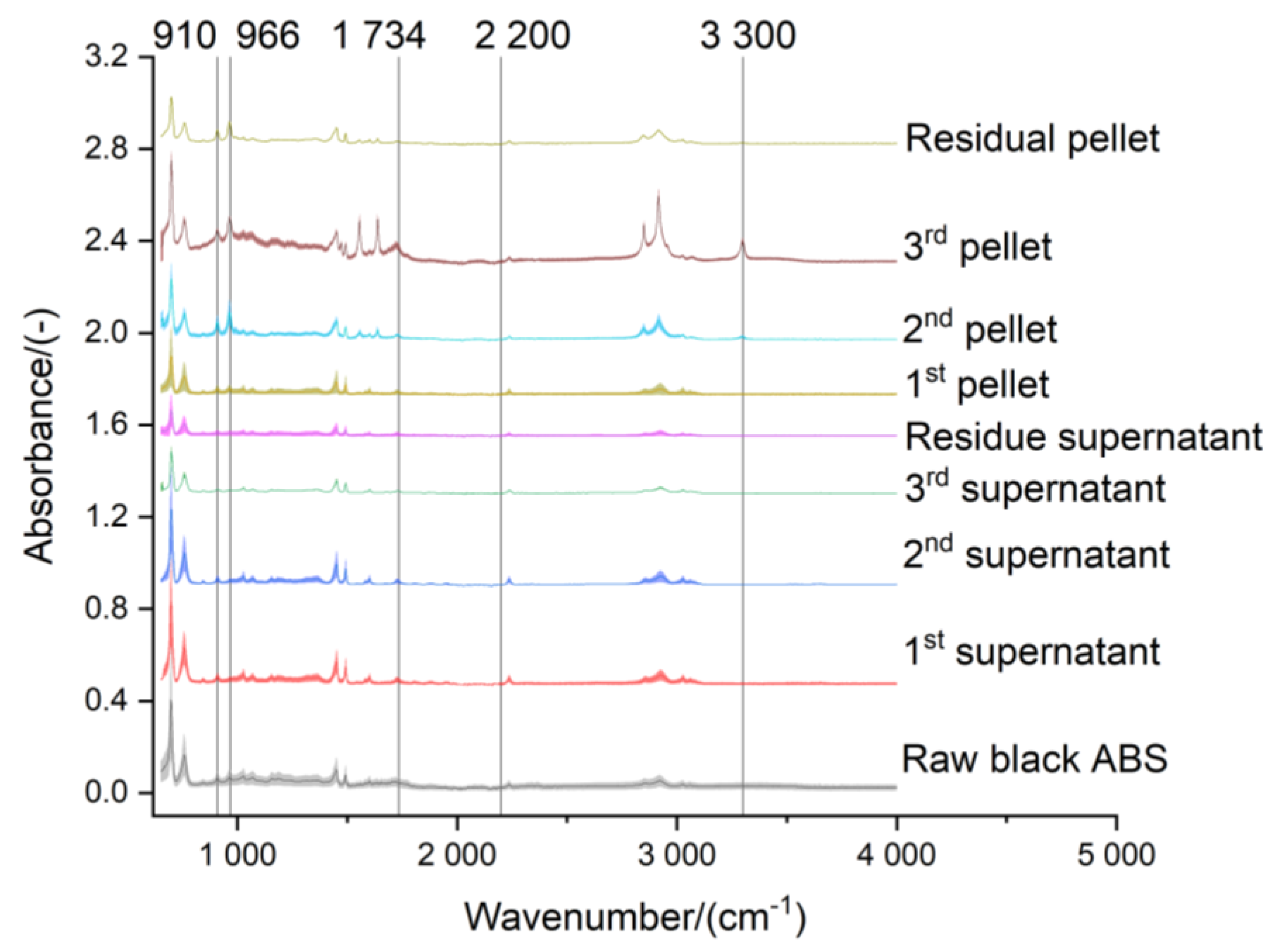
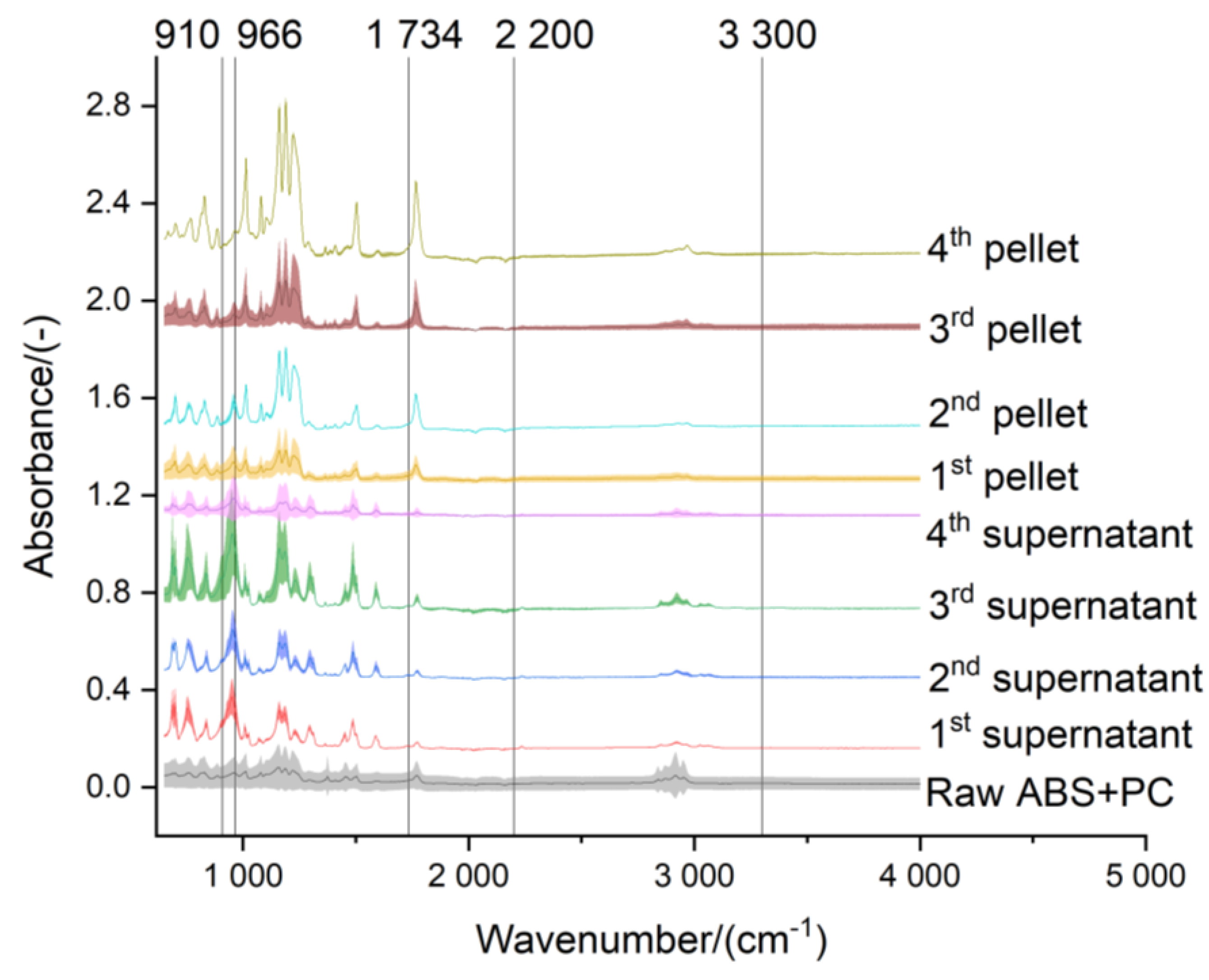
2.8. Acetone-Based Treatment of the ABS

Acetone smoothing is widely applied to polish the pieces of ABS prepared by additive manufacturing. This is because ABS is soluble in acetone and 3D printed parts have marks (Figure 7a,b) that need to be removed before reaching the final customer, in case the product is seen. For the sake of designing the valorization process of the e-waste plastic, the effect of the acetone treatment was analyzed at 2 levels: properties of the matrix of ABS and concentration of trace elements. Additionally, the treatments of the e-waste plastics with dichloromethane (DCM) and nitric acid were also evaluated.

2.8.1. Impact in the Properties of the Matrix

The chemical treatment of the ABS with acetone could hinder the recyclability of this polymer, due to the degradation of the less soluble fraction of rubbery dispersed phase of butadiene. The possible changes in the chemical structure of the extracted e-waste plastics were studied by FTIR (Figure 8, Figure 9 and Figure 10). The serial extractions (up to 4 times) were performed by mixing of 25 g of each e-waste plastic with 100 mL of acetone (fresh solvent added in each extraction step) for 30 min. The fraction of ABS extracted with the acetone was subdivided in the supernatant (most soluble molecules of the ABS) and the pellet. Additionally, the remaining residue after the serial extractions was similarly divided into supernatant and pellet. The most characteristic absorbance band of the ABS at approximately 2200 cm−1 (corresponding to the C≡N triple bond) could be seen in almost all the fractions of the e-waste plastics treated with acetone, with the exception of the ABS + PC (Figure 10) due to the lower concentration of the SAN copolymer. In agreement with the findings of Arostegui et al. [24], the degradation of ABS with the serial extraction procedure occurred in the pellet (i.e., butadiene-rich phase) and not in the more soluble SAN copolymer that mainly remained in the supernatant. In this way, the height of absorbance bands associated with the butadiene double bonds (910 cm−1 and 966 cm−1) significantly increased in the pellet-fraction. Furthermore, the absorbance band related to saturated carbonyl groups (1734 cm−1) was progressively built up, particularly in the pellet of the 3rd extraction of the black ABS (Figure 9). According to Kim and Kang [33], the enhancement of these absorbance bands was due to the degradation of the butadiene phase, especially in unsaturated bonds, leading to the formation of carbonyl groups. Additionally, the N-H stretching (3300 cm−1) could be identified in the pellet of the 3rd extraction of the black ABS, indicating that the butadiene also reacted with the acrylonitrile. Only 3 extraction steps were considered for the black ABS (Figure 9) because this type of e-waste plastic appeared to be more soluble in acetone than the white ABS. In the case of ABS + PC (Figure 10), the residue that remained after the 4 acetone-extractions was not analyzed because this SAN-depleted material was further treated with DCM for the extraction of the PC [34].
In addition to the interpretations based on the FTIR profiles of the acetone treated e-waste plastics, the TGA/DSC (Figures S38–S44) were also considered for the design of a more advantageous extraction step. The white ABS lost its functionality beyond the 2nd extraction, as can be seen in the smoother DSC curves in Figures S38 and S39. A single treatment with the nitric acid disabled any possible phase change in the white ABS (Figure S40). For the acetone-treatment of black ABS, 2 extraction steps were also found to be the optimum, since beyond that point the phase changes were minimized (Figures S41 and S42). Finally, for the valorization of the ABS + PC it might not have been convenient to conduct the 4th extraction step with acetone, as the trends of phase change in the DSC profiles (Figures S43 and S44) were different, which indicated easier degradation of the polymer due to the predominance of exothermic reactions at lower temperatures.

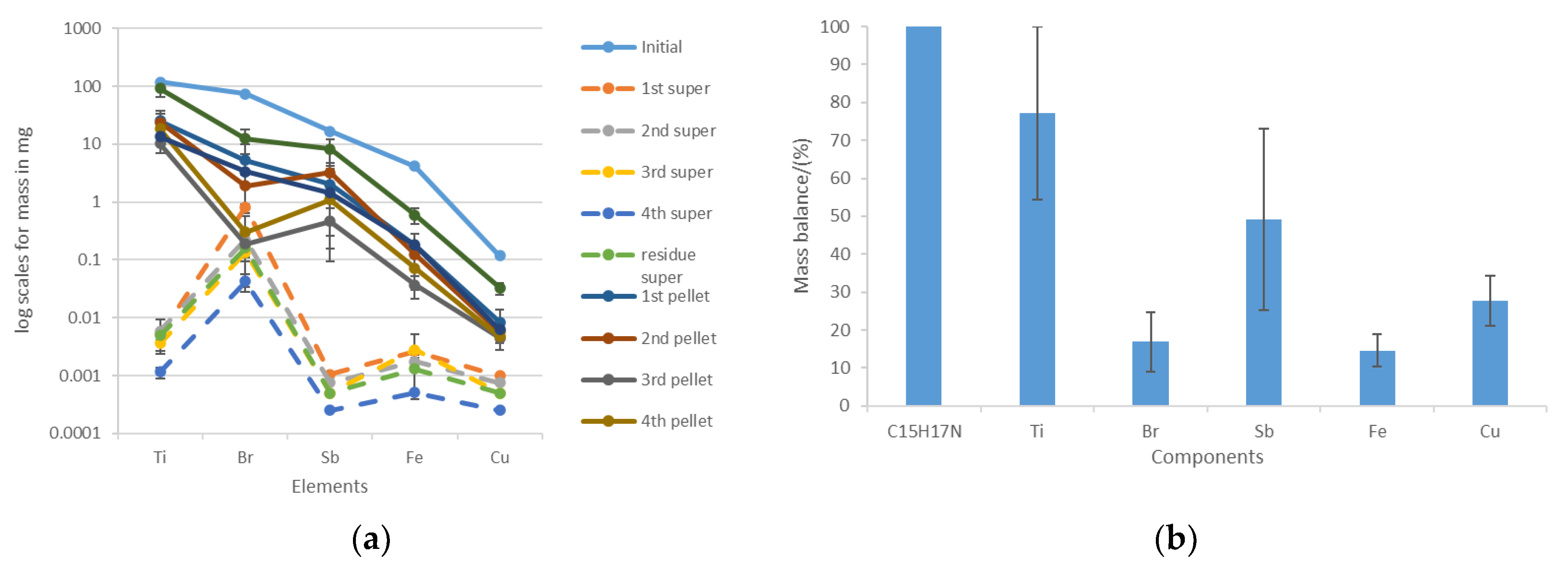
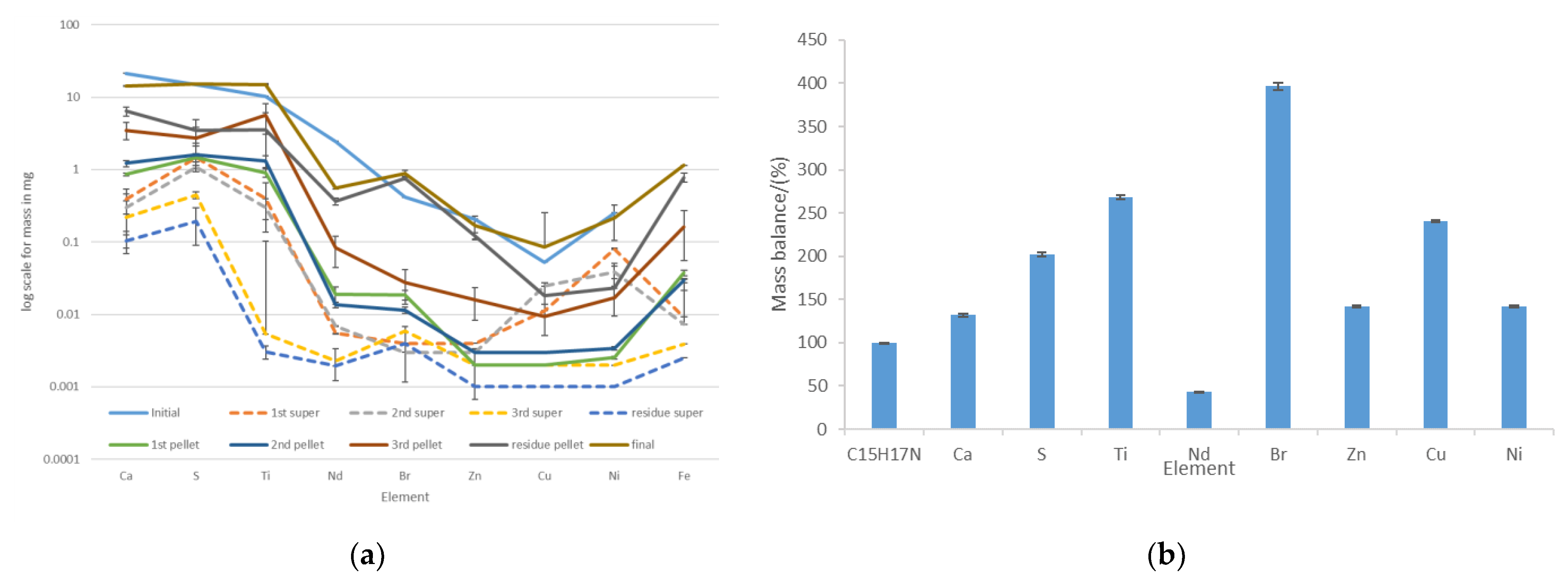
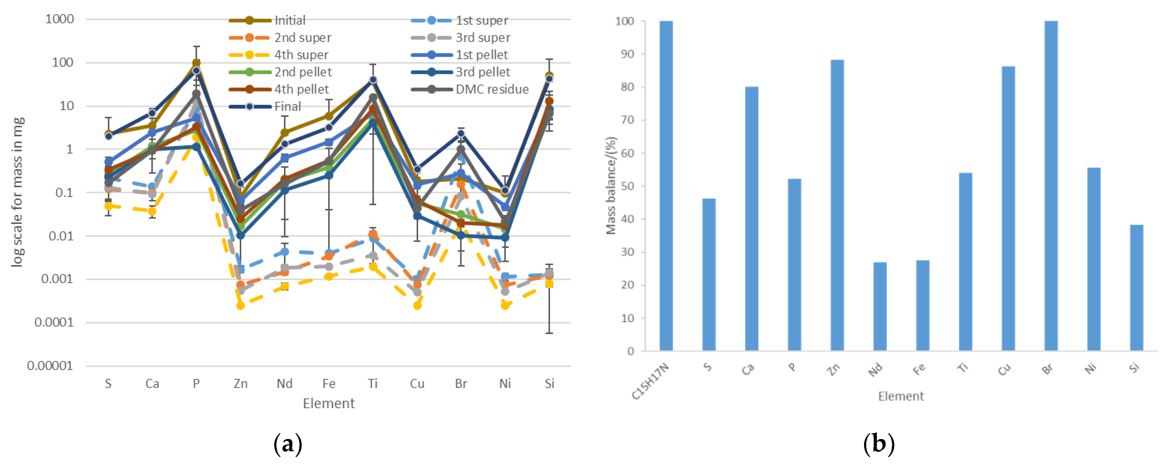
2.8.2. Change in the Composition of Trace Elements

Based on the results obtained for the white ABS (Figure 11a), the acetone treatment was very useful to extract the BFR, as the bromine had more affinity for the acetone than any of the other additives. Although the trends of Figure 11a are clear, it should be noted that the best mass balance was obtained for the titanium and implied that 77.22 ± 22.77% of the initial amount of this element was accounted in the fractions obtained with the 4-step extraction process: supernatant, pellet, and residue (Figure 11b). Similar to iron (14.57 ± 4.31%)), the bromine found was 16.90 ± 7.81% of the initial amount of this element in the white ABS (Figure 11b). This might be related to the fact that the quantification of the additives with XRF has limitations and other methods should be used for a greater accuracy, such as GC-MS for the bromine [15] and ICP-OES for the trace metals [1]. Nevertheless, XRF is a very useful technique for initial characterization and sorting of e-waste plastics based on the content of bromine. The acetone treatment might promote the volatilization of bromine; hence the extraction treatment needs to be robustly designed to prevent gaseous emissions. A cleaning system similar to CreaSolv® process needs to be conceived to ensure a close loop for the solvent and no emissions of volatile compounds [35,36]. Once the fraction of the white ABS had been solubilized, the repolymerization could be done with the antisolvent technique by adding water to the acetone solution. Following this procedure, the bromine concentration found in reprecipitated ABS (2.9 mg Br/kg) was much lower than the original concentration of this element in the raw white ABS sample (2939.3 mg Br/kg). This way of recycling the ABS minimized the volatilization of bromine, since this element remained in the acetone solution. In case evaporation was allowed, the addition of virgin ABS (1.0 mg Br/kg) could minimize the losses of bromine and produce a semi-recycled material with 163.0 mg Br/kg. The acetone extraction of bromine was more convenient and effective than the processes involving the use of more hazardous reagents, like the nitric acid (70 wt.%) that left the white ABS with a concentration of bromine of 305.0 mg/kg after 2 weeks of soaking with intermittent shaking (Table S1).
The acetone treatment of the black ABS was not as effective as the extraction of bromine in the white ABS. As can be seen in Figure 12a, the elements that had greater affinity for the organic solvent were copper and nickel. As most of the bromine was found in the less soluble pellet fraction, the mass balance was met (Figure 12b) because the losses via volatilization were minimized. As with the white ABS, the 2-week treatment of the black ABS with nitric acid (70 wt.%) had poor capacity of removing the bromine, but this soaking technique can be useful for other elements (Table S2): sulfur, neodymium, and nickel.
The last combination possible with the bromine’s affinity for the acetone and the recoverability of this element with the extraction method was observed with the ABS + PC (Figure 13). The processing of this type of e-waste plastic was characterized by the high affinity of the BFR for the acetone (Figure 13a), in addition to a high recoverability of this element (Figure 13b). Unlike in the acetone-based treatment of the white ABS, where also the BFR had good affinity for the solvent but low bromine recoverability was found, the acetone-based treatment of the ABS + PC was supplemented with DCM after the 4th extraction. The result found was that the recoverability of bromine increased significantly, although this effect might have also been associated with the type of BFR compound that the ABS + PC contained. Overall, the concentration of bromine increased from 8.29 ± 0.16 mg/kg in the raw ABS + PC to 201.8 ± 85.70 mg/kg in the acetone-DCM-treated ABS + PC.

3. Discussion

If recycled e-waste plastic is intended for the packaging of foodstuffs, the removal of BFR might be required due to their persistence in the environment and the risks that these chemicals pose to public health [37]. According to the European Food Safety Authority [37], the plastics containing BFR, whether in use or waste, leach these chemicals to the environment and contaminate air, soil, and water; hence, these pollutants may enter the food chain. The consolidated version of the Waste Electrical and Electronic Equipment (WEEE) Directive of the EU, implementing the decision 2018/2193, prescribes proper treatment for plastics containing BFR (Article 8 and Annex VII) [38]. On the other hand, the lobby of the bromine industry BSEF [39] conducted an independent study to justify their products of BFR [40], being supported by Sofies International B-Corp, a certified sustainability consulting firm [41]. The problems of BFR are also known in the UK, although the charity Breast Cancer UK highlights that the organic flame retardants (including BFR, chlorinated flame retardants, and organophosphorus flame retardants) are additive but they are not the most commonly used worldwide, unlike the aluminum hydroxide which constitutes 34% of the market [42]. Additionally, the Drinking Water Inspectorate confirmed the leachability of the BFR and identified those with high potential for occurrence in water sources in the UK [43]. The UK Government [44] requires a special application to stablish microfactories for e-waste plastics. Particularly, the Department for Environment, Food & Rural Affairs of the UK still considers the use of the Best Available Treatment, Recovery and Recycling Techniques for the removal of BFR from WEEE plastics [45]. Since the objective of removal is to ensure that BFRs do not enter the material stream, unless the BFR are extracted, it is not recommended to recycle plastics containing BFR [45]. XRF can be implemented as a quick technique to identify bromine in e-waste plastics, enabling the separation of plastics containing BFR prior to recycling, energy recovery, or disposal [46]; otherwise, the capacity of the current technologies for handling these materials will decrease [15]. In the case of the polybromodiphenyl ethers, which are a large group of 209 different types of BFR with similar chemical structure, the UK Government has provided specific guidance on how to respond to chemical incidents [47], as these compounds have particular potential to bioaccumulate in the environment [48], with the liver and thyroid being likely toxicity targets [49].
Given these limitations in the composition, a suitable application of the recycled filament was considering the manufacturing of hard drive caddies of different sizes. The different types of behavior of e-waste plastics determine their suitability for different applications. The best combination to meet the mechanical specifications would be a blend of black ABS and PP with a balance of stiffness and flexibility. Since several grades of virgin polymers are available in the market, the selection of the virgin material relied on the criteria of the MFI analysis. For example, for the ABS that is one of the polymers more widely used for 3D printing, the criterion was that the MFI should be around or below 10 g/10 min at 210 °C/10 kg (i.e., highly viscous materials). Materials with an MFI of 15 g/10 min at 210 °C/10 kg or greater are more suitable for recycling processes that include a molding-injection step rather than melt-blend extrusion, due to the lower viscosity required [23]. The MFI technique was not used for the characterization of the e-waste plastics but the difficulties in the operation of the melt-blend extrusion step are an indicator of the suitability of different materials for this type of valorization process. Figure 14a,b show several cross-sections of the clogging black ABS that originated due to factors such as unmelted particles (Figure 14c,d), high moisture content that prevented the proper flow of the material, or even metal particles (Figure S45a) that accompanied the e-waste plastic and could only be unblocked with the Devoclean MidTemp purge (Figure S45b). Figure 14e,f show a filament with an unmelted core that went through the extrusion step due to the fusion of the outer layer, which upon cooling become a crust. As explained above, the valorization of the black ABS was done in 2 separate runs (Figure 4a,b) due to this undesired clogging. In Figure 7 all pictures were taken at the same magnification (×5) but the black ABS (Figure 7d) can be clearly seen thicker than the other filaments. This could be an explanation for the significant greater tensile strength that was found for this material (Figure 6a), and agrees with the greater viscosity of the black ABS. Figure S46 offers the microscope pictures of the thickest filament prepared with the clogging black ABS, before it was necessary to introduce the Devoclean MidTemp purge to continue with the operation of the equipment. It is noteworthy to mention that a homogenous composition of the filament is essential, and that the tensile strength will not increase otherwise. For this reason, despite the greater thickness of the clogging ABS, the mechanical strength was not enhanced (Figure 6a) since the filament was heterogeneous (Figure S47).
Figure 15 depicts the layout of the microfactory for the manufacturing of hard drive caddies made of e-waste plastic. As part of the float-sink operation [1,50], the first tank full of water allows the mechanical separation of the PP (0.85–0.95 g/cm3) from the ABS (1.04–1.06 g/cm3) and the PC (1.20–1.22 g/cm3) [1]. In order to be able to separate the ABS and the PC, it would be necessary to use a solvent, such as DCM with a density of 1.33 g/mL and able to solubilize the PC [34]. Taking into account the problem of using DCM for Health & Safety, and environmental pollution, the manipulation of the density of the water with a brine of CaCl2 could be more feasible. The isolated e-waste plastics would be subsequently fed at different rates in the compounding step, including the use of additives. However, for complex mixtures of e-waste plastics the use of solvents (tertiary recycling) might be the only way to attain the complete separation for the polymer before the melt-blend extrusion [4]. After this float-sink operation, the detection of additives and flame retardants will be possible with portable handheld XRF equipment [51]. The results of the present investigation were considered to implement a short contact time between acetone and ABS. This extraction step would give the best results because it avoids excessive degradation of the matrix while still removing the BFR. The quick extraction of the trace elements of the ABS agrees with the techno-economic assessment of contact times lower than 90 min and avoid the degradation of the less soluble rubbery phase of butadiene [24].
In the next step of shredding, it is necessary to ensure a particle size below 2 mm for the melting of the e-waste plastic to be as efficient as possible. Once the recycled 3D filament has been produced, a key decision to make is the type of component that will be replicated by additive manufacturing (Figure S48). The optimization of the use of the recycled material can be done with the software UltiMaker Cura [52], which informs how much supporting material will be necessary to print a certain component (Figure S48a). It is regarded as supported material all the recycled plastic that will be printed to maintain the parts of the component being replicated which deviate by more than a 45° angle. In order to make this prediction, the only information that is required by the software is the computer-aided design (CAD) file with the dimensions of the component that is going to be printed. For the hard drive caddies printed with ABS, 30% of the recycled filament will be used as supportive material (Figure S48b). A recirculation loop has been included in Figure 15 to describe the mass flow of this supportive material that is removed from the printed component (Figure S48c) which needs to be reprocessed. Those components that require a large amount of supporting material when being printed might be more suitable for a microfactory involving a molding injection step rather than melt-blend extrusion. In case a visual element (e.g., screen frames of a laptop, mobile phone casings, etc.) is to be printed, an additional downstream process step would need to be included in Figure 15 for the acetone smoothing. This last step of upgrading the printed piece before reaching the end-user is a very simple technique in which the acetone vapors are forced to interact with the edges and surfaces of the component made of ABS, by means of a fan promoting turbulence in the closed environment. Thereby, the 2 main variables that needed to be considered for the successful design of the recycling process (Figure S48d,e) were: the (chemical and mechanical) properties of the e-waste plastic and the structure of the component that was going to be replicated.

4. Materials and Methods

The most abundant e-waste plastics available in a recycling site in the UK were identified based on the indented RIC and the FTIR spectra. These were: ABS, PC, and PP. Following the procedure described by Mikula et al. [8], the optimization of the recycling process relied on the analysis of the chemical, mechanical, and thermal properties of the e-waste plastics, the recycled filament, and the subsequently printed species. The difference in the composition of the matrix polymer (main component of the e-waste plastics) was characterized with the Cary 630 FTIR Spectrometer of Agilent Technologies, with ATR sampling module for reflection mode measurement. The data of transmittance (expressed in percentage) provided by this equipment was converted to absorbance by calculating the logarithm of transmittance divided by 100. Furthermore, the differences of the e-waste plastics in terms of the additives were characterized with XRF analysis: a Shimadzu EDX8000 instrument, equipped with an Rh sealed-source X-ray tube and a silicon strip detector. The samples were mounted on a Mylar film and were irradiated using a 5 mm in diameter collimator. Semi-quantitative concentrations were obtained using a Fundamental Parameter method. The washing of the raw materials with water and soap (following the procedure of Chandrasekaran et al. [34]) was synergistically used to evaluate the feasibility of the float-sink operation to classify the polymers.
The virgin materials to initiate the melt-blend extrusion process (HDPE, ABS, and PLA) were procured considering that these plastics should have an MFI below 10 (i.e., high viscosity). Before the melt-blend extrusion step, the reduction of the particle size to less than 5 mm was performed with the GP20 Shredder Hybrid of 3devo. The Precision 350 compounder of 3devo was used for processing the e-waste plastics following the protocols provided by the manufacturer of the equipment [21,22]. The Devoclean MidTemp purge material that initially contained the filament maker was purged with HDPE to ease the transition to the virgin ABS. In order to feed the virgin ABS, the settings used for the melt-blend extruder were: 4 heaters started at 240 °C, screw speed at 5 rpm, and fan capacity at 50%. Subsequently, the waste ABS was progressively introduced in the feedstock and once a stable operation was reached, the temperature of the heaters next to the feeding hoper was decreased down to 215 °C [21]. Although ABS does not absorb a lot of moisture during storage, the drying was performed at 80 °C for only 1 h in the Airid Polymer Dryer of 3devo B. V.
Similarly, the extrusion report prepared by 3devo was followed to assess the feasibility of recycling the waste PP. The virgin material that was used to ease the feeding of the PP was the PLA, using a bell-shaped setting of 170–175 °C for the heaters of the extruder [22]. The preparation of the dumbbell-shaped specimen was done with the ZMorph 2.0 SX Multitool 3D Printer. The analysis of the filament thickness was performed with the optical sensor installed in the compounder and the software DevoVision. The characterization of the tensile strength of the filament was done with the equipment Instron 3345, which would be able to provide up to 5 kN of traction and compression forces. The Olympus LEXT OLS5000 SAF Optical 3D Measuring Laser Microscope was used for the characterization of the breakage of the recycled filaments. For the thermogravimetric analysis and the differential scanning calorimetry, the NETZSCH STA 449 F3 Jupiter® was used. The acetone extraction of the white ABS was performed following a modified version of the protocol followed by Arostegui et al. [24]. The difference was that the samples were successively extracted up to 4 times, aiming for the isolation of the most soluble fractions of the matrix (SAN copolymer) and additives (BFR) and minimizing the degradation of the rubbery dispersed fraction (butadiene). The subsequent extraction of the PC in the case of the ABS + PC was performed with DCM, similarly to Chandrasekaran et al. [34].

5. Conclusions

The evaluation of the first step proposed for the microfactory on classifying the materials with the float-sink operation found that it was feasible given the low density of the PP, but the use of brine or organic solvents would be required for the separation of ABS and PC. Less hazardous solvents, such as acetone, were preferred to others that were able to extract the PC, such as the DCM. The recycling process could include the removal of BFR from the ABS, and this technology relied on the affinity of the bromine for the acetone. The design of a closed system, similar to that of the CreaSolv® process, is meant to reduce environmental pollution and enable the complete recycling of the acetone used as solvent. Among all the recycled materials, the greatest tensile strength was found for the black ABS and the greatest flexibility was seen in the filament of PP. Therefore, for the manufacturing of the hard drive caddies, a blend of these materials is proposed. The molding injection is more suitable than the 3D printing for plastic components of electrical devices that need to be replicated in very large quantities. The plastic component replicated by additive manufacturing should be selected carefully, minimizing the amount of supportive material that is generated and that would need to be removed and melted again for reprocessing. Despite the primary recycling strategy followed, which minimized the loss of additives and stabilizers of the polymers, the compounding of the ABS + PC resulted in a brittle and fragile filament for 3D printing. Thereby, the use of compatibilizers and impact modifiers, such as the ethylene-methyl acrylate-glycidyl methacrylate terpolymer, should be included in the formulation of the recycled material, at a rate of 5 wt.%.

Supplementary Materials

The following supporting information can be downloaded at: https://www.mdpi.com/article/10.3390/recycling8030046/s1, Figure S1: Laser microscope (×10) of the neck formation in the PP filament during the tensile test; Figure S2: Profile tensile force vs. extension of the white ABS filament and the dumbbell shaped specimen prepared following the British Standard EN ISO 527-2:2012 (test conditions for molding and extrusion); Figure S3: Lose threads that can be seen in the filament made of 50% virgin HDPE and 50% virgin ABS upon rupture in the tensile testing; Figure S4: Tensile testing profiles for: (a) Commercial black ABS (8 replicates), (b) acetone smoothen white ABS (8 replicates), (c) virgin ABS (9 replicates), and (d) 10% white ABS + 90% virgin ABS (10 replicates); Figure S5: Tensile testing profiles for: (a) 18% white ABS + 82% virgin ABS (10 replicates), (b) 35% white ABS + 65% virgin ABS (10 replicates), (c) 40% white ABS + 60% virgin ABS (15 replicates), and (d) 70% white ABS + 30% virgin ABS (10 replicates); Figure S6: Tensile testing profiles for: (a) 90% white ABS + 10% virgin ABS (10 replicates), (b) clogging ABS (10 replicates), (c) 50% white ABS + 50% black ABS (11 replicates), and (d) 50% ABS + PC + 50% black ABS (17 replicates); Figure S7: Tensile testing profiles for: (a) 50% black ABS + 50% HDPE (13 replicates), (b) 50% virgin ABS + 50% HDPE (10 replicates), (c) 50% PP + 50% PLA (21 replicates), and (d) 10% PP + 90% PLA (21 replicates); Figure S8: Thermogravimetric analysis (green line) and differencing scanning calorimetry (blue line) performed up to 600 °C (red line) for the white ABS: (a) unprocessed waste and (b) the 1.75-mm filament obtained with the melt-blend extrusion; Figure S9: Thermogravimetric analysis (green line) and differencing scanning calorimetry (blue line) performed up to 600 °C (red line) for the black ABS: (a) unprocessed waste and (b) the 1.75-mm filament obtained with the melt-blend extrusion; Figure S10: Thermogravimetric analysis (green line) and differencing scanning calorimetry (blue line) performed up to 600 °C (red line) for the ABS + PC: (a) unprocessed waste and in (b) the 1.75-mm filament obtained with the melt-blend extrusion; Figure S11: Thermogravimetric analysis (green line) and differencing scanning calorimetry (blue line) performed up to 600 °C (red line) for the PP: (a) unprocessed waste and in (b) the 1.75-mm filament obtained with the melt-blend extrusion; Figure S12: Thermogravimetric analysis (green line) and differencing scanning calorimetry (blue line) performed up to 600 °C (red line) for the virgin ABS: (a) unprocessed pellet and in (b) the 1.75-mm filament obtained with the melt-blend extrusion; Figure S13: Thermogravimetric analysis (green line) and differencing scanning calorimetry (blue line) performed at the temperature informed by the red line for: (a) white ABS filament @ 800 °C; (b) commercial black ABS filament @ 800 °C; (c) commercial black ABS filament @ 600 °C; (d) commercial green ABS @ 600 °C; Figure S14: Thermogravimetric analysis (green line) and differencing scanning calorimetry (blue line) performed up to 600 °C (red line) for: (a) fresh HDPE; (b) HDPE stored at room condition for a year; (c) MidTemp purge; (d) PLA filament; Figure S15: Comparisons of the FTIR spectra of the HDPE and the Devoclean MidTemp purge; Figure S16: Laser microscope images (×5) of the rupture of the filaments of Commercial black ABS filament in the tensile test; Figure S17: Laser microscope images (×5) of the failure of the filaments of 50% white ABS 50% Black ABS in the tensile test; Figure S18: Laser microscope images (×5) of the failure of the filaments of10% white ABS 90% virgin ABS in the tensile test; Figure S19: Laser microscope images (×5) of the rupture of the filaments of 18% white ABS 88% virgin ABS in the tensile test; Figure S20. Laser microscope images (×5) of the failure of the filaments of 25% white ABS 75% virgin ABS in the tensile test; Figure S21: Laser microscope images (×5) of the failure of the filaments of 35% white ABS 65% virgin ABS in the tensile test; Figure S22: Neck formation in the filaments of 35% white ABS 65% virgin ABS during the tensile test; Figure S23: Laser microscope images (×5) of the rupture of the filaments of 40% white ABS 60% virgin ABS in the tensile test; Figure S24: Neck formation in the filaments of 40% white ABS 60% virgin ABS in the tensile test; Figure S25: Laser microscope images (×5) of the rupture of the filaments of 70% white ABS 30% virgin ABS in the tensile test; Figure S26: Laser microscope images (×5) of the failure of the filaments of 70% white ABS 30% virgin ABS in the tensile test; Figure S27: Laser microscope images (×5) of the rupture of the filaments of 90% white ABS 10% virgin ABS in the tensile test; Figure S28: Laser microscope images (×5) of the failure of the filaments of virgin ABS in the tensile test; Figure S29: Laser microscope images (×5) of the rupture of the filaments of 50% HDPE and 50% Black ABS in the tensile test; Figure S30: Laser microscope images (×5) of the failure of the filaments of 50% HDPE 50% Black ABS in the tensile test; Figure S31: Laser microscope images (×5) of the rupture of the striations of the filament of ABS + PC; Figure S32: Laser microscope (×10) of the formation of 2 fibers in the PP filament during the tensile test; Figure S33: Laser microscope images (×5) of the neck formation in the filaments of 50% PP + 50% PLA during the tensile test; Figure S34: Laser microscope images (×5) of the failure of the filaments of 10% PP 90% PLA in the tensile test; Figure S35: Laser microscope images (×5) of the neck formation in the filaments of 10% PP 90% PLA during the tensile test; Figure S36: Laser microscope images (×5) of the rupture of the filaments of PLA; Figure S37: Laser microscope images (×5) of the failure of the filaments of PLA (with neck formation); Figure S38: TGA/DSC profiles of the fraction of white ABS isolated with the acetone extraction: (a) 1st supernatant, (b) 2nd supernatant, (c) 3rd supernatant, and (d) 4th supernatant; Figure S39: TGA/DSC profiles of the fraction of white ABS isolated with the acetone extraction: (a) 1st pellet, (b) 2nd pellet, (c) 3rd pellet, and (d) 4th pellet; Figure S40: TGA/DSC profiles of the fraction of the white ABS soaked for 2 weeks in nitric acid (70 wt.%) with intermittent shaking; Figure S41: TGA/DSC profiles of the fraction of black ABS isolated with the acetone extraction: (a) 1st supernatant, (b) 2nd supernatant, and (c) 3rd supernatant; Figure S42: TGA/DSC profiles of the fraction of black ABS isolated with the acetone extraction: (a) 1st pellet, (b) 2nd pellet, and (c) 3rd pellet; Figure S43: TGA/DSC profiles of the fraction of ABS + PC isolated with the acetone extraction: (a) 1st supernatant, (b) 2nd supernatant, (c) 3rd supernatant, and (d) 4th supernatant; Figure S44: TGA/DSC profiles of the fraction of ABS + PC isolated with the acetone extraction: (a) 1st pellet, (b) 2nd pellet, (c) 3rd pellet, and (d) 4th pellet; Table S1: Extraction of the white ABS with nitric acid (70 wt.%) conducted for 2 weeks with intermittent shaking; Table S2: Extraction of the black ABS with nitric acid (70 wt.%) conducted for 2 weeks with intermittent shaking; Figure S45: (a) Material that was found among the plastic e-waste. (b) Metal parts that remained inside the melt-blend extruder and they needed to be purged with Devoclean MidTemp (polyethylene); Figure S46: Laser microscope images (×5) of the rupture of the filaments of clogging ABS 100% in the tensile test; Figure S47: Laser microscope images (×10) of the failure of the filaments of Clogging ABS 100% in the tensile test; Figure S48: (a) UltiMaker Cura visualization of the supportive material (blue color) that will be required to print the hard drive caddies with ABS. (b) Printed hard drive caddies with ABS. (c) Removal of the supportive material (30% of the total ABS) from the hard drive caddies printed with ABS. (d) Proof that the small hard drive caddy fits for purpose. (e) Proof that the big hard drive caddy fits for purpose.

Author Contributions

Conceptualization, F.A.; methodology, A.M.A. and F.A.; software, A.M.A.; validation, A.M.A.; formal analysis, A.M.A.; investigation, A.M.A.; resources, F.A.; data curation, A.M.A.; writing—original draft preparation, A.M.A.; writing—review and editing, A.M.A. and F.A.; visualization, A.M.A.; supervision, F.A.; project administration, A.M.A. and F.A.; funding acquisition, A.M.A. and F.A. All authors have read and agreed to the published version of the manuscript.

Funding

This research was funded by the Accelerated Knowledge Transfer to Innovate (AKT2I) Pilot Scheme of the UKRI (Project Number 120 of Lancaster University).

Data Availability Statement

Restrictions apply to the availability of the data regarding the recycling company from where the e-waste plastics were sampled. Data of the stakeholders of this project is available upon request to the authors with the permission of third parties.

Acknowledgments

The authors would like to acknowledge the support received by Allan Rennie, Samuel Walsh, Jessica Fisher, Tom Abram, Sebastian Smith, and Nicholas Renninson, John Baum, and Nathan Halcovitch.

Conflicts of Interest

The authors declare no conflict of interest. The funders had no role in the design of the study; in the collection, analyses, or interpretation of data; in the writing of the manuscript; or in the decision to publish the results.

Abbreviations

Acrylonitrile-butadiene-styrene (ABS); Brominated flame retardants (BFR); Computer-aided design (CAD); Dichloromethane (DCM); Differential scanning calorimetry (DSC); Fourier-transform infrared spectroscopy (FTIR); Melt-flow index (MFI); Polycarbonate (PC); Polylactic acid (PLA); Polypropylene (PP); Thermogravimetric analysis (TGA); poly(styrene-acrylonitrile) (SAN); Waste Electrical and Electronic Equipment (WEEE); X-ray fluorescence (XRF).

References

  1. Jia, C.; Das, P.; Kim, I.; Yoon, Y.J.; Tay, C.Y.; Lee, J.M. Applications, treatments, and reuse of plastics from electrical and electronic equipment. J. Ind. Eng. Chem. 2022, 110, 84–99. [Google Scholar] [CrossRef]
  2. Parajuly, K.; Kuehr, R.; Awasthi, A.K.; Fitzpatrick, C.; Lepawsky, J.; Smith, E.; Widmer, R.; Zeng, X. Future E-Waste Scenarios. 2019. Available online: https://ewastemonitor.info/e-waste-will-double-by-2050/ (accessed on 29 March 2023).
  3. WRAP. WEEE Collections Monitoring. 2016. Available online: https://wrap.org.uk/resources/guide/weee-collection-guide (accessed on 29 March 2023).
  4. Sahajwalla, V.; Gaikwad, V. The present and future of e-waste plastics recycling. Curr. Opin. Green Sustain. Chem. 2018, 13, 102–107. [Google Scholar] [CrossRef]
  5. Das, A.; Debnath, B.; Chowdary, P.A.; Bhattacharyya, S. Paradigm Shift in E-Waste Management; CRC Press: New York, NY, USA, 2022. [Google Scholar] [CrossRef]
  6. Baldé, C.P.; D’Angelo, E.; Luda, V.; Deubzer, O.; Kuehr, R. The Global Transboundary E-Waste Flows Monitor 2022; International Telecommunication Union: Bonn, Germany, 2022; Available online: https://ewastemonitor.info/wp-content/uploads/2022/06/Global-TBM_webversion_june_2_pages.pdf (accessed on 29 March 2023).
  7. Martinho, G.; Pires, A.; Saraiva, L.; Ribeiro, R. Composition of plastics from waste electrical and electronic equipment (WEEE) by direct sampling. Waste Manag. 2012, 32, 1213–1217. [Google Scholar] [CrossRef] [PubMed]
  8. Mikula, K.; Skrzypczak, D.; Izydorczyk, G.; Warchoł, J.; Moustakas, K.; Chojnacka, K.; Witek-Krowiak, A. 3D printing filament as a second life of waste plastics—A review. Environ. Sci. Pollut. Res. 2021, 28, 12321–12333. [Google Scholar] [CrossRef]
  9. Hunt, E.J.; Zhang, C.; Anzalone, N.; Pearce, J.M. Polymer recycling codes for distributed manufacturing with 3-D printers. Resour. Conserv. Recycl. 2015, 97, 24–30. [Google Scholar] [CrossRef]
  10. 3devo B.V. Research Your Own 3D Printing Materials. Innovate Right from Your Desk. 2022. Available online: https://www.3devo.com/ (accessed on 29 March 2023).
  11. 3devo B.V. DevoVision: Visually Understand Your Material, Experiments, and Production. Products. 2022. Available online: https://www.3devo.com/devovision (accessed on 18 April 2023).
  12. 3devo B.V. Composer and Precision Filament Makers. Shop. 2022. Available online: https://www.3devo.com/shop (accessed on 18 April 2023).
  13. Woern, A.L.; McCaslin, J.R.; Pringle, A.M.; Pearce, J.M. RepRapable Recyclebot: Open source 3-D printable extruder for converting plastic to 3-D printing filament. HardwareX 2018, 4, e00026. [Google Scholar] [CrossRef]
  14. Boz Noyan, E.C.; Venkatesh, A.; Boldizar, A. Washing Post-Consumer Flexible Polyethylene Packaging Waste. Recycling 2022, 7, 90. [Google Scholar] [CrossRef]
  15. Evangelopoulos, P.; Arato, S.; Persson, H.; Kantarelis, E.; Yang, W. Reduction of brominated flame retardants (BFRs) in plastics from waste electrical and electronic equipment (WEEE) by solvent extraction and the influence on their thermal decomposition. Waste Manag. 2019, 94, 165–171. [Google Scholar] [CrossRef]
  16. Zhan, F.; Zhang, H.; Cao, R.; Fan, Y.; Xu, P.; Chen, J. Release and Transformation of BTBPE During the Thermal Treatment of Flame Retardant ABS Plastics. Environ. Sci. Technol. 2019, 53, 185–193. [Google Scholar] [CrossRef]
  17. Environment Agency. Polybrominated Diphenyl Ethers (PBDEs): Sources, Pathways and Environmental Data; Environment Agency: Bristol, UK, 2019. Available online: https://consult.environment-agency.gov.uk/environment-and-business/challenges-and-choices/user_uploads/polybrominated-diphenyl-ethers-pressure-rbmp-2021.pdf (accessed on 29 March 2023).
  18. He, Z.; Li, G.; Chen, J.; Huang, Y.; An, T.; Zhang, C. Pollution characteristics and health risk assessment of volatile organic compounds emitted from different plastic solid waste recycling workshops. Environ. Int. 2015, 77, 85–94. [Google Scholar] [CrossRef]
  19. Hirayama, D.; Nunnenkamp, L.A.; Braga, F.H.G.; Saron, C. Enhanced mechanical properties of recycled blends acrylonitrile–butadiene–styrene/high–impact polystyrene from waste electrical and electronic equipment using compatibilizers and virgin polymers. J. Appl. Polym. Sci. 2022, 139, 51873. [Google Scholar] [CrossRef]
  20. da Silva Müller Teixeira, F.; de Carvalho Peres, A.C.; Gomes, T.S.; Visconte, L.L.Y.; Pacheco, E.B.A.V. A Review on the Applicability of Life Cycle Assessment to Evaluate the Technical and Environmental Properties of Waste Electrical and Electronic Equipment. J. Polym. Environ. 2021, 29, 1333–1349. [Google Scholar] [CrossRef]
  21. 3devo B.V. ABS Extrusion Report. 2019. Available online: https://4595257.fs1.hubspotusercontent-na1.net/hubfs/4595257/Knowledge%20Base%20Import/ABS-Material-Report.pdf (accessed on 29 March 2023).
  22. 3devo B.V. PP Extrusion Report. Available online: https://4595257.fs1.hubspotusercontent-na1.net/hubfs/4595257/Support%20Platform/downloadable%20PDF/Recycled-PP-Material-Report.pdf (accessed on 29 March 2023).
  23. 3devo B.V. Material Selection—Choosing the Right Polymer. Support. 2023. Available online: https://support.3devo.com/guide-material-selection (accessed on 18 April 2023).
  24. Arostegui, A.; Sarrionandia, M.; Aurrekoetxea, J.; Urrutibeascoa, I. Effect of dissolution-based recycling on the degradation and the mechanical properties of acrylonitrile–butadiene–styrene copolymer. Polym. Degrad. Stab. 2006, 91, 2768–2774. [Google Scholar] [CrossRef]
  25. Ramesh, V.; Biswal, M.; Mohanty, S.; Nayak, S.K. Recycling of engineering plastics from waste electrical and electronic equipments: Influence of virgin polycarbonate and impact modifier on the final performance of blends. Waste Manag. Res. 2014, 32, 379–388. [Google Scholar] [CrossRef]
  26. 3devo B.V. Filament Maker Quality Check. Support. 2022. Available online: https://support.3devo.com/filament-maker-quality-check (accessed on 18 April 2023).
  27. BSI EN ISO 527-2:2012; Plastics—Determination of Tensile Properties. Part 2: Test Conditions for Moulding and Extrusion Plastics. British Standards Intitution: London, UK, 2012. Available online: https://landingpage.bsigroup.com/LandingPage/Standard?UPI=000000000030216860 (accessed on 29 March 2023).
  28. Zhang, J.; Hirschberg, V.; Rodrigue, D. Blending Recycled High-Density Polyethylene HDPE (rHDPE) with Virgin (vHDPE) as an Effective Approach to Improve the Mechanical Properties. Recycling 2022, 8, 2. [Google Scholar] [CrossRef]
  29. Yahiaoui, M.; Denape, J.; Paris, J.Y.; Ural, A.G.; Alcalá, N.; Martínez, F.J. Wear dynamics of a TPU/steel contact under reciprocal sliding. Wear 2014, 315, 103–114. [Google Scholar] [CrossRef]
  30. Jin, D.W.; Shon, K.H.; Jeong, H.M.; Kim, B.K. Compatibility enhancement of ABS/polycarbonate blends. J. Appl. Polym. Sci. 1998, 69, 533–542. [Google Scholar] [CrossRef]
  31. Duan, H.; Xin, M.-Q.; Kim, K.-Y.; Tang, J.-J. The Role of Compatibilizers on the Properties of PC/ABS Alloy. J. Mater. Sci. Chem. Eng. 2017, 5, 21–30. [Google Scholar] [CrossRef]
  32. Pelto, J.; Barreto, C.; Anwar, H.; Strobl, L.; Schlummer, M. Compatibilized PC/ABS blends from solvent recycled PC and ABS polymers from electronic equipment waste. Polym. Test. 2023, 120, 107969. [Google Scholar] [CrossRef]
  33. Kim, J.K.; Kang, C.K. Basic Studies on Recycling of ABS Resin. Polym. Plast. Technol. Eng. 1995, 34, 875–890. [Google Scholar] [CrossRef]
  34. Chandrasekaran, S.R.; Avasarala, S.; Murali, D.; Rajagopalan, N.; Sharma, B.K. Materials and Energy Recovery from E-Waste Plastics. ACS Sustain. Chem. Eng. 2018, 6, 4594–4602. [Google Scholar] [CrossRef]
  35. Schlummer, M.; Wolff, F.; Maurer, A. Recovery of PC/ABS from WEEE plastic shred by the CreaSolv® process. In Proceedings of the 2016 Electronics Goes Green 2016+ (EGG), Berlin, Germany, 6–9 September 2016. [Google Scholar] [CrossRef]
  36. Schlummer, M.; Mäurer, A.; Leitner, T.; Spruzina, W. Report: Recycling of flame-retarded plastics from waste electric and electronic equipment (WEEE). Waste Manag. Res. 2006, 24, 573–583. [Google Scholar] [CrossRef] [PubMed]
  37. EFSA. Brominated Flame Retardants. Available online: https://www.efsa.europa.eu/en/topics/topic/brominated-flame-retardants#:~:text=Other%20brominated%20flame%20retardants.%20These%20classes%20have%20been,the%20risks%20these%20chemicals%20pose%20to%20public%20health (accessed on 29 March 2023).
  38. Directive 2012/19/EU of the European Parliament and of the Council of 4 July 2012 on Waste Electrical and Electronic Equipment (WEEE). Available online: https://eur-lex.europa.eu/legal-content/EN/TXT/PDF/?uri=CELEX:32012L0019&from=EN (accessed on 29 March 2023).
  39. BSEF. About BSEF. Available online: https://www.bsef.com/about-us/about-bsef/ (accessed on 29 March 2023).
  40. Sofies. Study on the Impacts of Brominated Flame Retardants on the Recycling of WEEE Plastics in Europe. 2020. Available online: https://www.bsef.com/wp-content/uploads/2020/11/Study-on-the-impact-of-Brominated-Flame-Retardants-BFRs-on-WEEE-plastics-recycling-by-Sofies-Nov-2020.pdf (accessed on 29 March 2023).
  41. BSEF. Brominated Flame Retardants Are Not Hindering the Recycling of WEEE Plastics Says New Study. 2020. Available online: https://www.bsef.com/news/sofiesreport/ (accessed on 29 March 2023).
  42. UK Breast Cancer. Flame Retardants. 2017. Available online: https://www.breastcanceruk.org.uk/app/uploads/2019/08/Background_Briefing_Flame_retardants_21.9.17_IS_nw.pdf (accessed on 29 March 2023).
  43. Crookes, M.; Brooke, D.; Bums, J. Brominated Flame Retardants—Risks to UK Drinking Water Sources. 2009. Available online: https://dwi-content.s3.eu-west-2.amazonaws.com/wp-content/uploads/2020/10/27110953/DWI70_2_219.pdf (accessed on 29 March 2023).
  44. UK Government. Waste Electrical and Electronic Equipment (WEEE): Reuse and Treatment. 2019. Available online: https://www.gov.uk/guidance/waste-electrical-and-electronic-equipment-weee-reuse-and-treat (accessed on 29 March 2023).
  45. DEFRA. Guidance on Best Available Treatment Recovery and Recycling Techniques (BATRRT) and Treatment of Waste Electrical and Electronic Equipment (WEEE). 2006. Available online: https://webarchive.nationalarchives.gov.uk/ukgwa/20130402151656/http://archive.defra.gov.uk/environment/waste/producer/electrical/documents/weee-batrrt-guidance.pdf (accessed on 29 March 2023).
  46. WRAP. Develop a Process to Separate Brominated Flame Retardants from WEEE Polymers. 2006. Available online: https://www.researchgate.net/publication/236838704_WRAP_Project_PLA-037_develop_a_process_to_separate_brominated_flame_retardants_from_WEEE_polymers_Interim_Report_2_The_Waste_and_Resources_Action_Programme_Banbury_UK (accessed on 29 March 2023).
  47. UK Government. Brominated Flame Retardants: Incident Management and Toxicology. 2018. Available online: https://www.gov.uk/government/publications/brominated-flame-retardants-properties-incident-management-and-toxicology (accessed on 29 March 2023).
  48. Birnbaum, L.S.; Staskal, D.F. Brominated flame retardants: Cause for concern? Environ. Health Perspect. 2004, 112, 9–17. [Google Scholar] [CrossRef]
  49. Toxicology Department Public Health England. Polybromodiphenyl Ethers (Decabromodiphenyl Ether): General Information. 2009. Available online: https://assets.publishing.service.gov.uk/government/uploads/system/uploads/attachment_data/file/341393/Deca_BDE_General_Information_phe_v1.pdf (accessed on 29 March 2023).
  50. Poulakis, J.G.; Papaspyrides, C.D. Recycling of polypropylene by the dissolution/reprecipitation technique: I. A model study. Resour. Conserv. Recycl. 1997, 20, 31–41. [Google Scholar] [CrossRef]
  51. Dimitrakakis, E.; Janz, A.; Bilitewski, B.; Gidarakos, E. Determination of heavy metals and halogens in plastics from electric and electronic waste. Waste Manag. 2009, 29, 2700–2706. [Google Scholar] [CrossRef] [PubMed]
  52. UltiMaker. UltiMaker Cura. 2011. Available online: https://ultimaker.com/software/ultimaker-cura (accessed on 18 March 2023).
Figure 1. Bulkiest e-waste plastics identified in the recycling company in the UK: (a) raw samples and (b) shredded samples to particle size below 5 mm: white ABS (top-left corner), black ABS (top-right corner), ABS + PC (bottom-left corner), and PP (bottom-right corner).
Recycling 08 00046 g001
Figure 2. Characterization of the composition of the e-waste plastics (ABS, PC, and PP) and the virgin polymers used to enable the melt-blend extrusion process for the production of 3D filament: (a) matrix in terms of FTIR spectra; (b) additives as described by the XFR results.
Recycling 08 00046 g002
Figure 3. (a) Progressive increase in the share of e-waste plastic (white ABS) and decrease in that of the virgin polymer (ABS). (b) 3D filament spools prepared with 100% recycled material: white ABS, black ABS, ABS + PP, and PP.
Recycling 08 00046 g003
Figure 4. Filament diameter obtained via melt-blend-extrusion of different e-waste plastics: (a) white ABS (initial 2 h) and black ABS (remaining 2 h); (b) ABS + PC (initial 4 h) and black ABS (remaining 4 h); (c) PP; (d) quality check with PLA.
Recycling 08 00046 g004
Figure 5. (a) 3D printing of the dumbbell shaped specimen for tensile testing; (b) dumbbell shaped specimen (zoom in); (c) 1.75 ± 0.20-diameter lumps (red circles) in the 3D filament (100% white ABS); and (d) 2-cm particles in shredded white ABS (red circle).
Recycling 08 00046 g005
Figure 6. (a) Summary of the mechanical strength of the 3D filament; (b) profile tensile force vs. extension of the 7 replicates of the white ABS filament; (c) profile tensile force vs. extension of the 8 replicates of the black ABS filament; (d) profile tensile force vs. extension 11 replicates of the ABS + PC filament; and (e) profile tensile force vs. extension of the 17 replicates of the PP filament.
Recycling 08 00046 g006
Figure 7. (a) Dumbbell shaped specimen after the tensile testing; (b) laser microscope image (×5) of the dumbbell shaped specimen at the point of failure; (c) laser microscope image (×5) of the white ABS filaments at the point of rupture; (d) laser microscope image (×5) of the black ABS filaments at the point of failure; (e) laser microscope image (×5) of the ABS + PC filaments at the point of rupture; and (f) laser microscope image (×5) of the PP filaments at the point of failure.
Recycling 08 00046 g007
Figure 8. Effect of the acetone extraction on the functional groups of the white ABS.
Recycling 08 00046 g008
Figure 9. Effect of the acetone extraction on the functional groups of the black ABS.
Recycling 08 00046 g009
Figure 10. Effect of the acetone extraction on the functional groups of the ABS + PP.
Recycling 08 00046 g010
Figure 11. Acetone-based extraction of the most abundant trace elements in the white ABS: (a) distribution of the elements among the supernatant and the pellet after each extraction step; (b) mass balances considering the initial amount of trace elements that were initially in the white ABS and the amounts that were found in the supernatant and the pellet.
Recycling 08 00046 g011
Figure 12. Acetone-based extraction of the most abundant trace elements in the black ABS: (a) distribution of the elements among the supernatant and the pellet after each extraction step; (b) mass balances considering the initial amount of trace elements that were initially in the black ABS and the amounts that were found in the supernatant and the pellet.
Recycling 08 00046 g012
Figure 13. Acetone-based extraction of the most abundant trace elements in the ABS + PC: (a) distribution of the elements among the supernatant and the pellet after each extraction step; (b) mass balances considering the initial amount of trace elements that were initially in the ABS + PC and the amounts that were found in the supernatant and the pellet.
Recycling 08 00046 g013
Figure 14. (a) laser microscope image (×10) of several cross-sectional areas of the filament of black ABS with unmelted particles; (b) laser microscope image (×10) several cross-sectional areas of the filament of black ABS with unmelted core; (c) laser microscope image (×20) of the cross-section of the filament of black ABS with unmelted particles; (d) laser scan (×20) of the cross-sectional area of the filament of black ABS with unmelted particles; (e) laser microscope image (×20) of the cross-section of the filament of black ABS with unmelted core; and (f) laser scan (×20) of the cross-sectional area of the filament of black ABS with unmelted core.
Recycling 08 00046 g014aRecycling 08 00046 g014b
Figure 15. Design of a microfactory for the manufacturing of hard drive caddies with the recycled e-waste plastic polymers: ABS, PC, and PP. The interfaces of the software Fusion 360 of Autodesk and UltiMaker Cura represent the stages of selecting the most suitable component to be replicated by preparing the CAD file and evaluating the amount of supportive material required.
Recycling 08 00046 g015
Disclaimer/Publisher’s Note: The statements, opinions and data contained in all publications are solely those of the individual author(s) and contributor(s) and not of MDPI and/or the editor(s). MDPI and/or the editor(s) disclaim responsibility for any injury to people or property resulting from any ideas, methods, instructions or products referred to in the content.

