Article

Numerical Modeling of Thermochemical Conversion of Biomass and Tires as Fuels for Cement Clinker Production

by
Baby-Jean Robert Mungyeko Bisulandu
1,2,3,* and
Frédéric Marias
1
1
Laboratoire de Thermique, Energétique et Procèdes-IPRA, University Pau & Pays Adour, EA1932, 64000 Pau, France
2
Institut de Recherche Futuris—Futuris Research Institute (InReF), OEFC & Faculté Polytechnique, Université Kongo, Mbanza-Ngungu B.P. 202, Kongo Central, Democratic Republic of the Congo
3
Institut National du Bâtiment et des Travaux Publics (INBTP), Département de Génie Rural, Kinshasa B.P. 4731, Democratic Republic of the Congo
*
Author to whom correspondence should be addressed.
Recycling 2023, 8(2), 41; https://doi.org/10.3390/recycling8020041
Submission received: 25 February 2023 / Revised: 31 March 2023 / Accepted: 3 April 2023 / Published: 6 April 2023
(This article belongs to the Special Issue Recycling and Recovery of Biomass Materials II)

Abstract

:

Highlights

Modeling of a cement rotary kiln with energy supplied by alternative fuels is carried out.
The quality of the cement obtained in both cases (biomass and tires) is studied.
The impacts of material properties of alternatives fuels are investigated.
Pyrolysis of biomass and tires takes place soon after their entrance into the rotary kiln.
The conditions of Portland cement are obtained.

Abstract

This article presents the numerical modeling of the thermochemical conversion of biomass and tires as alternative fuels in kilns dedicated to the production of cement. The study seeks to understand and control the phenomena that occur when heavy fuel oil (traditional fuel) is partially replaced by biomass and tires. These are thoroughly mixed with meal at the entrance to the rotary kiln and form the bed of solids. The mathematical model developed takes into account both chemical reactions of meal and alternative fuels. At the entrance, the meal is made up of species such as CaCO3, MgCO3, Al2O3, SiO2, Fe2O3, MgO, CaO, C2S, C3A, C4AF and C3S, some of which form along the kiln. The article focuses specifically on the influence of alternative fuels on the clinker or cement obtained. The properties (moisture, organic matter, composition, energy value, etc.) of the biomass and the tires, which are associated with the operating parameters of the kiln, greatly influence the production of clinker. In order to understand and control the behavior of each material and the operating parameters in the clinker (cement) production process, the mathematical model follows the evolution of each species and parameters step-by-step, until the clinker is obtained. The effect of alternative fuels on clinker production was found for the kiln’s operational parameters, the dynamic angle of the bed (30°), the angle of inclination of the kiln (2°), rotation (2 rpm), the length and the inside diameter, respectively (80 m) and (4 m); the chemical and physical properties (humidity, organic, inorganic matter, C, H, O, N, S, Cl); the lower calorific value, raw material); and the numerical parameters (spatial discretization 30 and 120). Despite the high energy content of tire fuels, the results of the use of biomass give better characteristics of clinker/cement (52.36% C3S and 3.83% CaO).The results found show that biomass pyrolysis is endothermic, with the heat of reaction found to be r H p y r o = 184.9   kJ / kg , whereas for tires, a heat of reaction of r H p y r o = 1296.3   kJ / kg was found, showing that the pyrolysis of this material is exothermic. Char production is higher in the case of tires than in the case of biomass, with rates of 0.261 kg/kgOrg.Mat. and 0.196 kg/kgOrg.Mat., respectively. In both cases, waste conversion was complete (100%). The cement obtained in the different cases meets the requirements of Portland cements (73.06% silicates and 18.76% aluminates), the conversion of alternative fuels is complete (100%), and the specific energy consumption is almost consistent with values from the literature.

1. Introduction

Faced with the issues of pollution, climate change, and the reduction in fossil fuel sources, the cement industry is geared toward resolving the following questions. Is there any fuel on the market to substitute for coal (or heavy fuel oil, or even LPG gas) which would have acceptable energy values and be less polluting? What are the reserves of alternative fuels capable of ensuring a sustainable method of cement production? What are the possible consequences of the use of waste on the cement manufacturing process, and on the quality of the clinker and/or cement? The current tendency to use alternative fuels in cement kilns can be explained by the increased exploitation and depletion of fossil fuel reserves, which impacts the soaring cost of fossil fuels. Alternative fuels are also used as part of the energy transition, a policy of that promotes the use of less-polluting, greener energies [1]. Numerous environmental codes governing the limitation of greenhouse gas emission have forced industries to reduce emission into the atmosphere for fear of paying high penalties [2]. The recovery of waste/biomass in the cement plant requires in-depth studies, a task that can be complex and multifaceted. Because alternative fuels proceed from several varieties of waste, a careful study of their constitution and composition must be conducted as far as their use in the kiln is concerned, in order to identify a fuel that meets the specifications of cement plants. The energy recovery of waste being on the agenda in a growing number of countries, many industries have been called upon to diversify their modes of energy production (electric or thermal) and minimize the cost of production, while safeguarding the environment. In the cement plant, thermochemical recovery of waste has already been implemented by quite a big number of cement factories. This article is grounded in the analysis and assessment of two categories of waste: biomass and tires. Biomass is a biological material derived from life or living organisms, recently produced directly or indirectly through photosynthesis, most often from plants or material derived from plants [3]. Biomass resources are widely available in nature. Global biomass production is around 100 billion tons per year [3]. Biomass is one of the most widely used wastes for alternative fuel in industrial processes and in the cement industry due to its availability and lower cost. Biomass is made up of various agricultural residues, such as sugar cane bagasse, peanut shells, almond shells, straw, rice husks and coffee husks, as well as residues from forest products, such as wood chips, sawdust, and bark. The use of biomass to provide partial substitution for fossil fuels is of the utmost importance with regard to global warming, since the combustion of biomass has the potential to be CO2 neutral [4]. This is particularly the case with agricultural residues that are regularly planted and harvested [5]. Agricultural residues are characterized by higher volatile matter contents than other wastes and coals. Thermochemical conversion processes are an important option for the recovery of energy and chemicals contained in biomass [6]. Unlike biomass, the waste resulting from tires has a high calorific value (the same order of magnitude as that of coal, or even higher), and the same carbon content [7]. With over a billion cars and trucks on the road daily, the number of tires in use naturally quadruples. In the long run, they end up in landfills, which can have extremely negative effects on the environment. Instead of discarding these tires in landfills, owners can recycle or dispose of them properly to avoid environmental pollution and reduce greenhouse gas emissions when they are burned separately (waste burned in incinerators without the purpose of energy and material recovery). Used tires are considered a very promising fuel in the cement industry for the following reasons: they have (1) high calorific values, ranging from 28–37 MJ/kg [6,7], and (2) a rich composition in carbon (used tires are characterized by low moisture and ash contents and by a high organic matter content). Tires contain polymeric aromatic structures, making them similar to coal in some respects [8]. The use of used tires as an alternative fuel is currently very popular. Some cement factories now favor tires over coal because of their energy values. However, tire conversion can be difficult. The disposal of tires is extremely difficult due to their highly resistant chemical, biological and physical properties [9]. It would seem that cement kilns are best suited for the thermochemical conversion of tires, given their operating temperatures. The high content of sulfur in fuels derived from tires constitutes the only major defect of their use in cement kilns. Sulfur is responsible for the formation of SOx, an unwanted chemical species in the kiln system. It is therefore important to use different SOx trapping techniques.
When these wastes are used in cement kilns, they undergo a thermochemical transformation. Many scholars have published their findings on the thermochemical transformation of alternative fuels in cement kilns. Oboirien and North [10] shared their view on tire gasification as being inadequately researched. They recommended the co-gasification of used tires with biomass, which is conducive to increasing the rate of gasification of the tires and reducing the cost of methanol production. Building on their research on the CFD modelling of meat and bone meal combustion in a cement rotary kiln, Ariyaratne et al. [11] have analyzed the effects of fuel supply and the impacts of fuel particle sizes on combustion, only to show that devolatilization is much faster in the case of small particles. They write: “For a given fuel, the higher the mass-weighted average particle diameter, the lower the coal depletion”. They further argue that the negative effect of a large weighted average particle size on coal depletion is greater for fixed high-carbon fuels. Babler et al. [12] develop an unsteady 1D pyrolysis model of biomass in the rotary kiln to optimize bio-char production. Their study is based on the conservation equations of mass and energy. Their model also includes independent sub-models dedicated to the pyrolysis reaction, heat transfer and granular flow in the rotary kiln. They notice that the increase in the speed of rotation of the furnace causes a decrease in the residence time. Nonetheless, it allows a good granular mixture in the bed of solids, which improves the heat transfer, and manifests itself in a rapid increase in bed temperature. Ariyaratne et al. [11] state that the biomass fuels are not only neutral, but they have the potential to decrease the impact of greenhouse gases. Failing to treat them will cause these fuels to produce methane and other decomposing products during decay. Such gases greatly exceed the potency of CO2 as greenhouse gases. Mungyeko Bisulandu and Marias [13] developed a one-dimensional model of thermochemical transformation of biomass in cement rotary kilns. They found that the drying and pyrolysis were carried out quickly, given the temperature level of the cement kilns, and that the chemical reactions were of first order. Nielsen [14] studied the devolatilization and combustion of tires, and of pinewood in a pilot-scale rotary kiln, under conditions similar to those of the input end of the meal to rotary kilns. Marias et al. [15] presented a mathematical model with three sub-models (the bed model, the kiln model, the gas model) for the pyrolysis of aluminum scrap, with the aim of predicting the physico-chemical processes occurring when this waste is introduced to the rotary kiln. This model is mainly based on the description and the coupling of the first two models. Pieper et al. [16] studied the impact of the coating layers on the clinker production process in a rotary kiln, wherein the fuel injected into the main burner is a mixture of pulverized coal and waste-derived fuel (RDF). The results show that the coating layers make it possible to stabilize the temperature of the kiln and reduce the free lime content of the final clinker. Kara [17] examined the feasibility of using waste-derived fuels (RDF) as an alternative fuel in the cement manufacturing process, and the possibility of supplying the necessary energy in the kiln system. He also examined emissions resulting from the substitution of petroleum coke by RDF. Gao et al. [18] reviewed different thermochemical processes (pyrolysis, co-pyrolysis and catalytic pyrolysis, gasification and combustion for process intensification, energy recovery) in order to valorize sewage sludge. These scholars claim that it is possible to recover the ash from the combustion of sewage sludge in the production of cement and in the preparation of concrete. Jiang et al. [19] offered a comprehensive methodology of the thermochemical treatment of municipal sludge, including combustion, pyrolysis, hydrothermal carbonization, liquefaction, wet oxidation, supercritical water oxidation and gasification. New findings prove that the thermochemical pyrolysis process is a promising method for treating waste tires [2]. Jiang et al. [19] also confirmed the suitability and superiority of thermochemical treatment regarding volume reduction and conversion of the municipal sludge product.
There seem to be a limited number of articles focused on the critical study of thermochemical transformation, most of which (including those mentioned above) suffer from a number of limitations and shortcomings.
There is a need to optimize the substitution to make it compatible with the quality of the cement. The properties of cement are generally influenced by the composition of its raw materials (clay and limestone), and by the thermal and mechanical treatment of the clinker. The composition of the clinker depends primarily on the chemical and mineralogical nature of the mixture of raw materials [20]. Fuels (fossil and alternative) can also influence the quality of the clinker. Alternative fuels very often contain high compounds of ash and moisture, organic compounds, heavy metals, circulating elements (Na, K, Cl, S, ...), and volatile substances [21]. Because of their variable composition, the use of alternative fuels in the cement plant can alter the quality of the clinker (or cement), if no action is taken to measure the waste to be replaced in the rotary kiln. For instance, chlorine is an element to avoid, because its presence (high content) in the cement causes problems of corrosion of armatures (reinforcement) or steels in the concrete and disturbs the setting and hardening of the cement. In view of the above, the substitution must be optimized to produce a better-quality cement at a low energy cost while protecting the environment. Optimizing substitution means carrying out analyses and upstream verification of the waste likely to be used in the cement plant. Several scholars have shared their preliminary analyses of waste before its use. Tsiliyannis [21], for one, offers new guidelines of key importance, namely the verification of the calorific value, the pollutants and circulating elements present in the waste, the quality of the waste, compliance with the environment, and the economic benefit linked to the cost of waste. He asserts that compliance with the above specifications is an important step in mastering the substitution and production of a good quality of cement. Mokrzycki and Uliasz-Bocheńczyk [22] recommend analysis of the following properties before the substitution of waste in the rotary kiln can be made: the physical state of the fuel (solid, liquid, gaseous), the contents of the circulating elements (Na, K, Cl, S), the toxicity (organic compounds, heavy metals), composition and ash content, volatile content, energy value, physical properties (size, density, homogeneity), grinding properties, moisture content, and the proportions of fossil–alternative dosing. For Zabaniotou and Theofilou [23], the use of alternative fuels in a cement plant must be performed with care. The choice of fuels must be based on several criteria, notably price and availability, energy content, and the ash, moisture, and volatile contents. Analysis of the fuels that will be used in the cement manufacturing process is a very important step to prevent the final product (cement) from being altered.
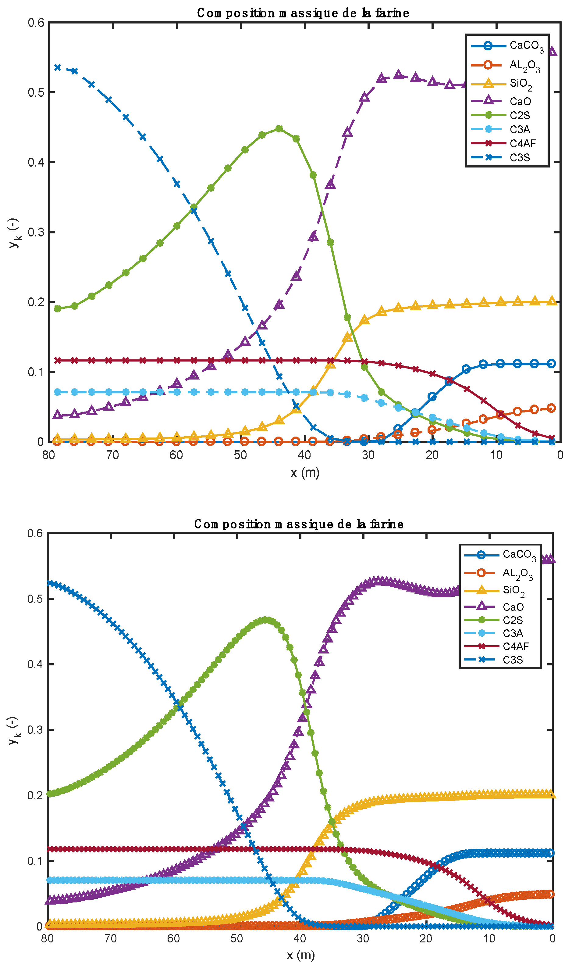
There is also a necessity to understand and prioritize the phenomena present in the rotary kiln. The rotary kiln for cement production is the seat of several thermochemical phenomena; it is necessary to understand and prioritize them both at the level of clinker manufacture (clinkerization reactions) and at the level of heat treatment of alternative fuels for modeling this type of installation. The meal reactions in the rotary kiln occur chronologically, as follows: heating and decarbonation of CaCO3, formation of the first clinker species, 2(CaO).SiO2, 3(CaO).Al2O3, 4(CaO).Al2O3.Fe2O3, and the liquid phase, and finally formation of the last species of clinker, 3(CaO).SiO2 [24,25]. For waste/biomass, the following phenomena can occur: drying of wet waste/biomass, pyrolysis of waste/biomass, combustion and gasification of the solid residue (char), and homogeneous combustion of the gases formed. To these physicochemical phenomena, it is necessary to add the thermal exchanges between the gases, the bed of solids, and the walls of the kiln.
In the literature, there are several works that deal with processes occurring in cement rotary kilns when waste is used, but very few works study and analyze in depth the thermochemical phenomena related to the substitution of fossil fuels by alternatives fuels.
The objective of this article is to model numerically the thermochemical conversion of biomass and tires as alternative fuels in kilns dedicated to the production of cement, trying to understand, master and control the phenomena that occur when the heavy fuel oil (traditional fuel) is partially replaced by biomass and tires. The study also considers the relevant process parameters of the kiln, and the effect of the physical and mass properties of alternative fuels on the quality of clinker produced (the specific objective of this study). It finally proposes to compare two scenarios of thermochemical transformation (heavy fuel + biomass; heavy fuel + tires), with a view to analyze and assess the manufacturing process of cement for each type of used waste.
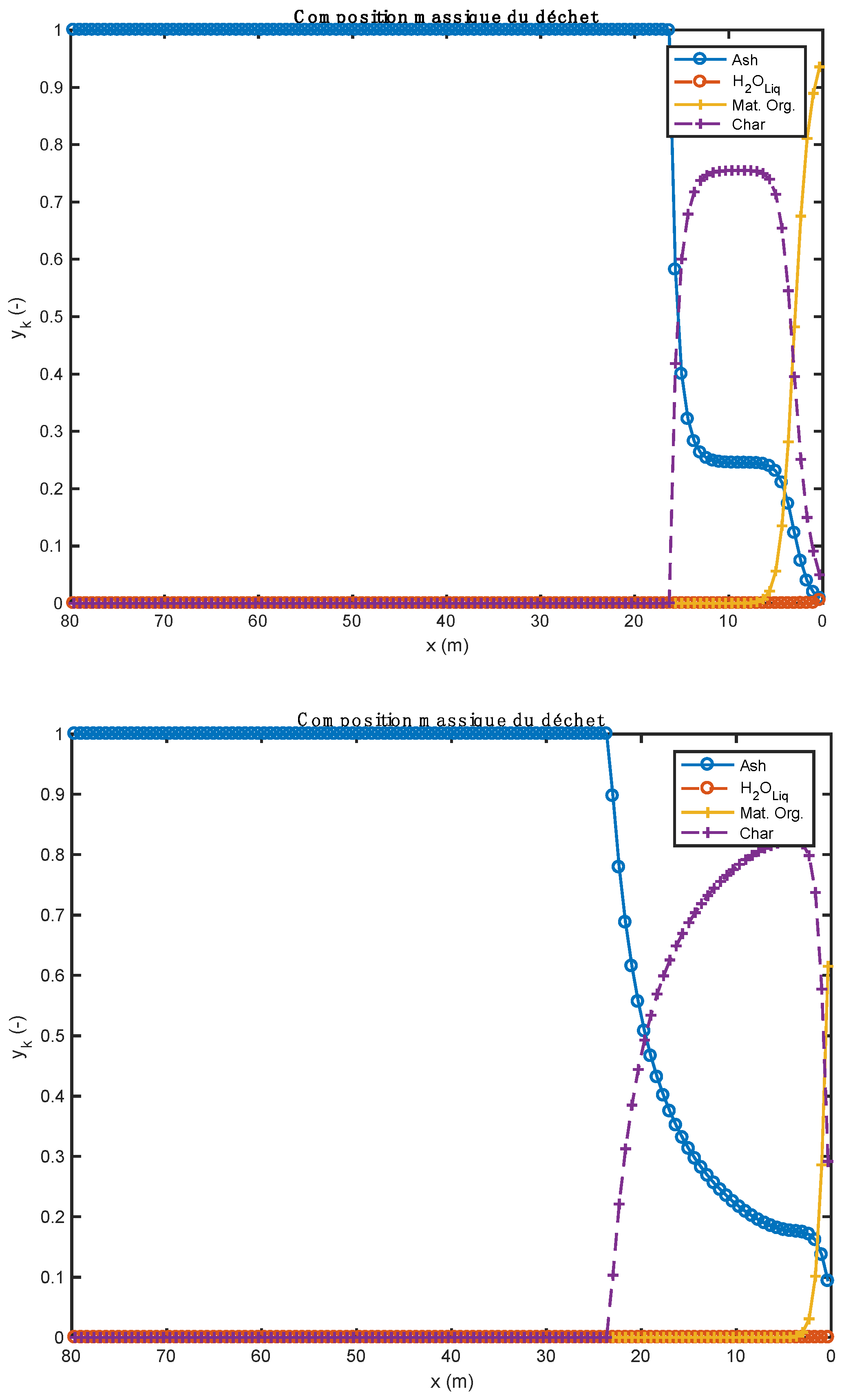
The bed material, seemingly a plug flow reactor, comprises cement meal and waste (biomass or tires), two materials that are perfectly mixed. In fact, the cement clinker contains the following compounds: CaCO3, MgCO3, Al2O3, SiO2, Fe2O3, MgO, CaO, 2(CaO).SiO2 or C2S, 3(CaO).Al2O3 or C3A, 4(CaO).Al2O3.Fe2O3 or C4AF, and 3(CaO).SiO2 or C3S undergoing thermochemical transformation.
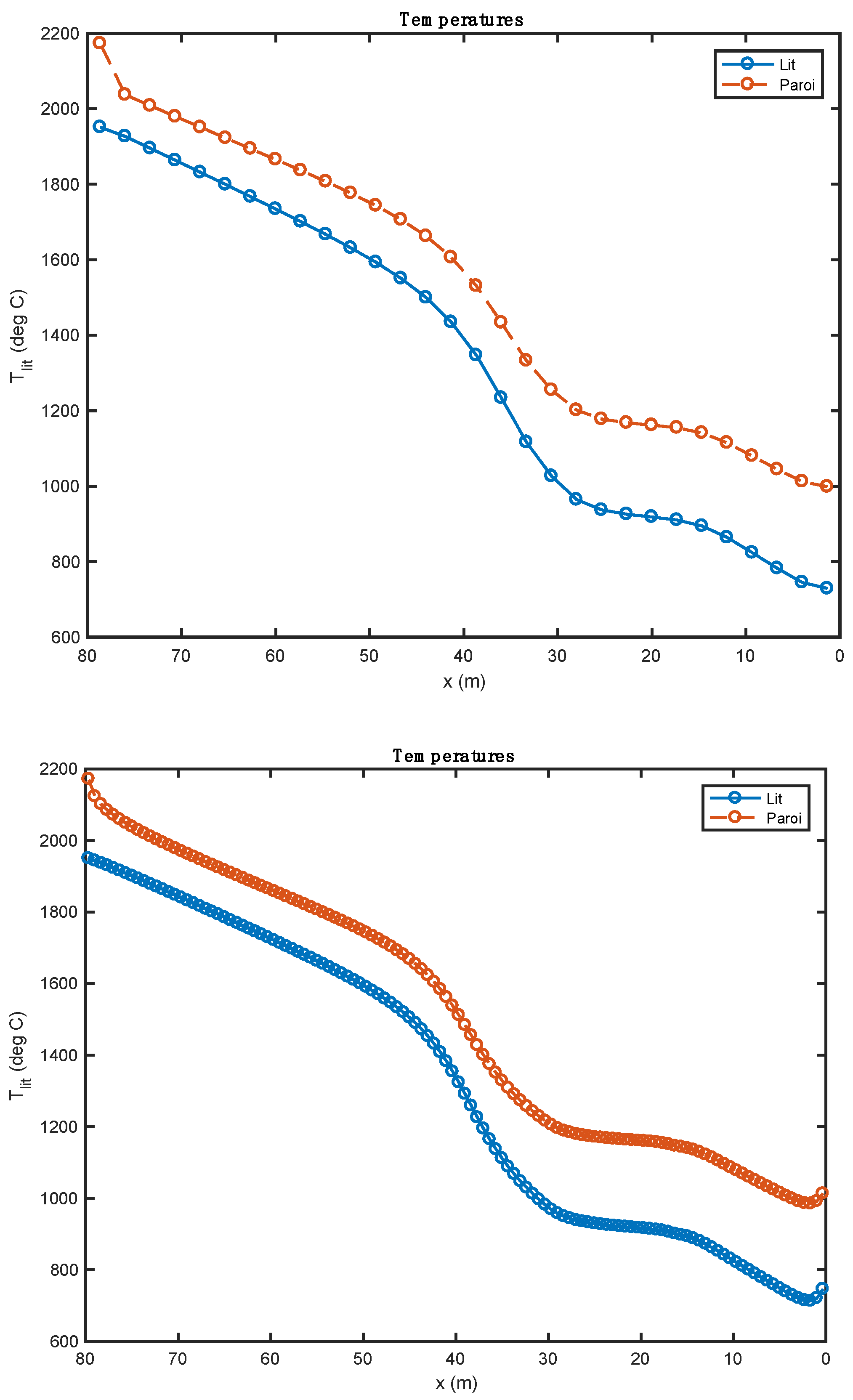
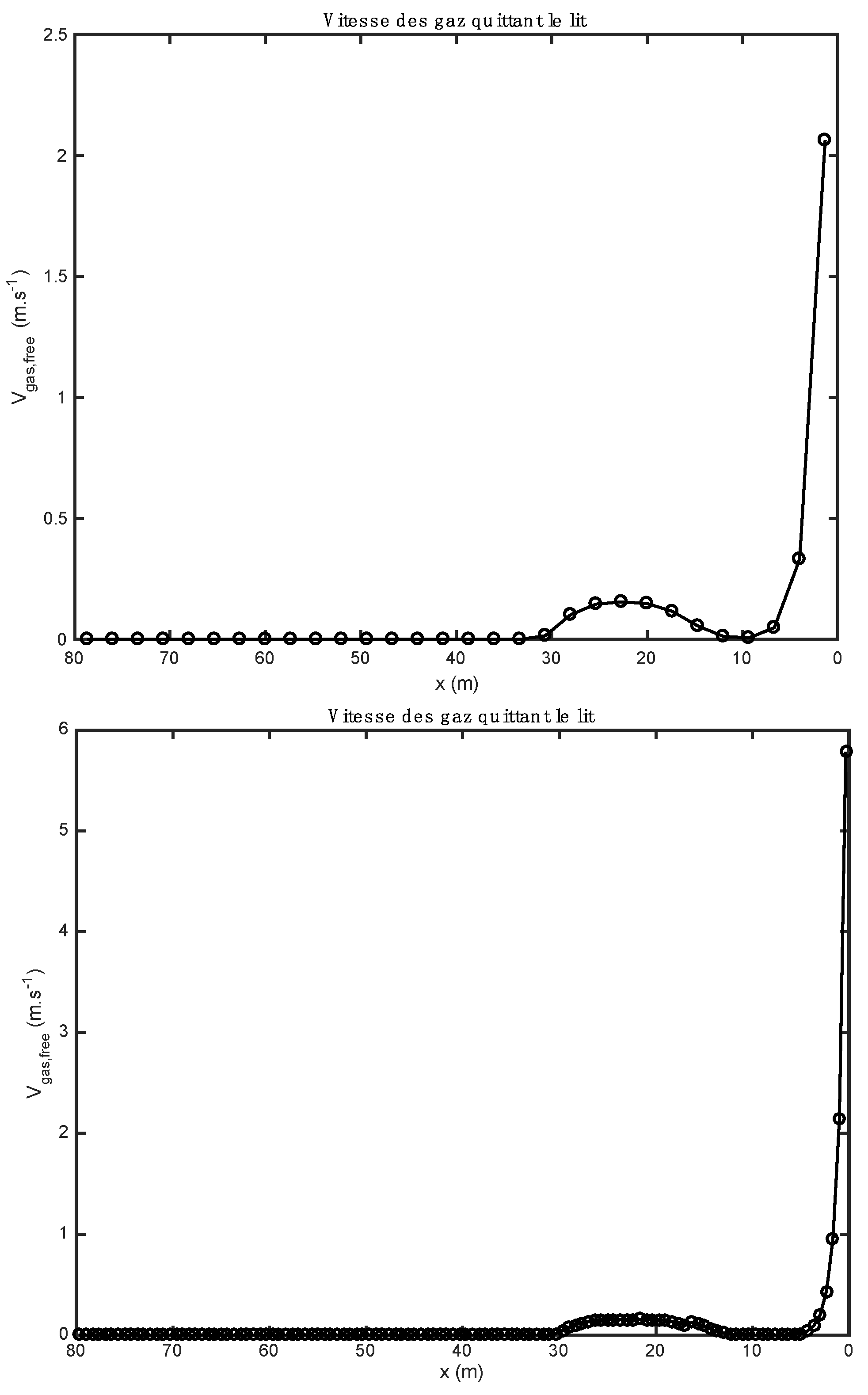
The results of this model are presented and discussed for each simulation category: (1) heavy fuel oil + biomass; (2) heavy fuel oil + tires.

2. Materials and Methods

This portion of the study focuses on the partial substitution of waste tires (characterized by the truck tire rubber [26], whose chemical composition is given in Table 4 below) and biomass (agricultural residues, characterized by beech particles [27], whose chemical composition is given in Table 4, below) in rotary kilns for cement production. For that, a mathematical model has been established, characterized in its first part (bed model) by the mixing of cement meal, waste (tires) and/or biomass, and gas. The second part provides the heat exchanged (kiln envelope model). The modeling work is performed using the Fortran 90 programming language, in which the conservation equations for mass, species and energy, the load transport equation and the algebraic equations are implemented. As for the exchanges with the gas phase, our team had to impose the densities of heat flux received by the solids bed and by the open wall of the kiln. The gas contained above the free surface of the bed is assumed to have a uniform value along the kiln axis in order to qualify the overall behavior of the model. MatLab software was used for the figures of the evolution of different variables of the model. The kiln studied is a rotary kiln dry process with preheater, equipped with a precalciner and cooler balloon, of the Lukala cement plant (CILU) in the Democratic Republic of Congo. This kiln was manufactured by the FL Smidth Company. The kiln has a length of 80 m, an inner diameter of 4 m and an outer diameter of 4.24 m. Its inclination is 2.0°, while its rotation speed is 2.0 rpm. A total of 175 t/h of raw material are fed to the kiln. These operational parameters are indeed the characteristics of rolling mode; they fulfil the condition 0.5 × 10⁻³ < Fr < 0.2 × 10⁻¹.

3. Numerical and Physical Modeling

The present model is characterized by two types of models: the solid bed model and the kiln shell model. The equations of these models form a system of algebra-differential equations.

3.1. Conservation and Other Equations

The mathematical equations translating the conservation of mass, chemical species and energy, and transport of the charge (transversal plane and longitudinal plane) are given in Table 1.
Equation (1) follows from the first-order Taylor’s development ( d d z ρ b e d A b e d u b e d y f a b e d y k f a Δ z = A b e d Δ z R k F a , F a ). It reflects the conservation of the chemical species k contained in the meal, and allows us to determine the value of the mass fractions of the species k of the meal of the bed. It is established by considering a control volume A l i t Δ z located at a certain axial position (z) of the bed. The mass flow rate of species k contained in the meal y k f a and entering the control volume can be expressed by:
- ρ b e d ( z ) A b e d ( z ) u b e d ( z ) y f a b e d ( z ) y k f a ( z )
After passing through the control volume, this mass flow became:
- ρ b e d z + Δ z A b e d z + Δ z u b e d z + Δ z y f a b e d z + Δ z y k f a z + Δ z
The variation in this mass flow is associated with the net specific production flow of species k ( ( R k F a , F a ) ) within the slice, in kg of k per s and per m3 of bed. This net specific flow rate is associated with the different chemical reactions taking place in the meal (and only concerning the meal species). Equation (2) represents the summation of these equations and allows us to determine the mass fraction of meal in the bed y f a b e d . Regarding waste, a balance sheet similar to that of meal species is written; this leads to Equation (3). In expression (3), y q d e c and R q d e c , d e c designate, respectively, the mass fraction of species q in waste, and the net specific rate of production of waste species (moisture, organic matter, char, ash) by waste degradation reactions. The summation of the conservation equations relating to the waste makes it possible to determine the mass fraction of the waste contained in the bed y d e c b e d (Equation (4)).
The writing of the conservation equations of the gaseous species contained in the bed is quite similar to the previous case. Nevertheless, considering certain meal transformation reactions (decarbonation, etc.) and waste (drying, pyrolysis, combustion and gasification), this time, there are three distinct sources for the net specific flows to be considered. Moreover, the existence of a gas flow leaving the bed towards the freeboard leads to the writing of Equation (5). In expression (5), R b g a s , g a s denotes the net specific rate of species b associated with homogeneous reactions in the gas phase, while R b d e c , g a s and R b f a , g a s denote respectively the net specific flow rates of production of gas species b by the decomposition reactions of waste and meal. The term ρ g a s denotes the density of the gas (in kg of gas per m3 of gas), which can be easily calculated from the composition of the gas and the temperature of the bed. y b g a s is the mass fraction of species b in gas. The width of the bed l b e d z , for its part, can be evaluated by relation (12). Equation (6) represents the summation of these equations and makes it possible to determine the mass fraction of gas in the bed y g a s b e d . The bed speed u b e d is determined by the relationship (7). Equation (8) represents the conservation of energy over a slice of the bed. On a slice of bed thickness Δ z , three distinct components are at the origin of the energy transfer between the slice and the external environment: (a) the departure of gas from the bed to the freeboard (corresponding to the excess gas generated by the heterogeneous reactions), (b) the transfer of energy between the gas contained in the freeboard and the bed (radiation and convection), and (c) the energy transfer between the kiln wall and the bed (by conduction and convection).
In expression (8), h b e d denotes the enthalpy of the bed. The heat flux density received from the freeboard by the bed is designated by φ f r e e , b e d . The evaluation of this flux density will be carried out using the CFD model of the freeboard, which will consider the radiation of the gases located above the bed and associated with the flame of the burner and the gas phase combustion of the products of pyrolysis. φ k i l n , b e d , meanwhile, designates the heat flux density transmitted by the kiln to the bed of solids. Finally, h g a s designates the specific enthalpy of the gas contained in the bed. Relation (9) makes it possible to estimate the enthalpy of the bed h b e d at the inlet of the rotary kiln. This is the weight sum of the enthalpies of bed species (meal, waste and gas). The bed density is calculated by the relation (10). Equations (11) and (13)–(15) allow us, respectively, to determine the bed intercept angle δ b e d z , the cross-sectional area of the bed A b e d , the height of the bed H b e d z and the volume flow rate of the materials in the kiln q v ( z ) . Equation (16) allows us to estimate the kiln wall temperature T k i l n . This represents the energy balance on the kiln walls, where:
-
λ k i l n designates the thermal conductivity of the kiln (refractory), assumed to be independent of temperature in the context of our work;
-
S t r a n s designates the transverse surface of the kiln wall whose refractory thickness is equal to e r e f r a c : S t r a n s = π d k i l n + 2 e r e f r a c 2 4 π d k i l n 2 4 ;
-
S d e c o u v designates the uncovered surface of the kiln exposed to radiation and convection in the gas phase: S d e c o u v = 2 π δ b e d d k i l n 2 Δ z ;
-
φ f r e e , k i l n designates the heat flux density received by the wall from the gas contained in the kiln. As in the case of the gas–bed heat transfer, this quantity will be taken from the CFD model of the gas phase of the bed.
-
S c o u v designates the covered surface of the kiln which is exposed to heat transfer with the load: S c o u v = δ b e d d k i l n 2 Δ z
-
φ k i l n , b e d designates the heat flux density transferred by the wall of the furnace to the moving load. In accordance with works in the literature [15,28,29,30], this heat flux density is evaluated by φ k i l n , b e d = h k i l n , b e d T k i l n T b e d , where h k i l n , b e d denotes the conducto-convective transfer coefficient between the charge and the wall of the oven. In the context of this work, and in accordance with the literature [31,32], the value of h k i l n , b e d = 300   ( W · m 2 · K 1 ) is used.
-
S e x t designates the outer surface of the kiln, which is used for heat exchange between the kiln and the outside: S e x t = π d f o u r + 2 e r e f r a c Δ z
-
φ k i l n , e x t designates the heat flux density exchanged between the wall of the kiln and the external environment. This flux density is evaluated by φ k i l n , e x t = h e x t T e x t T k i l n , where h e x t is the heat transfer coefficient between the wall of the kiln and the external environment. A value of h e x t = 15   ( W · m 2 · K 1 ) , classic in the context of an exchange of the external natural convection type, will be retained in the context of this work.
The summary of the different variables of this model is given in Table 2.

3.2. Solid Bed Model

3.2.1. Reactions Associated with Cement Meal

The chemical reactions occurring during clinker formation are provided below. As part of this work, we choose to use the mechanism described by [28]:
CaCO 3 s k 1 CaO s + CO 2 g 2 CaO s + SiO 2 s k 2 2 CaO . SiO 2 s 2 CaO . SiO 2 s + CaO s k 3 3 CaO . SiO 2 s 3 CaO s + Al 2 O 3 s k 4 3 CaO . Al 2 O 3 s 4 CaO s + Al 2 O 3 s + Fe 2 O 3 s k 5 4 CaO . Al 2 O 3 . Fe 2 O 3 s
The writing of the speeds of these reactions is based on the work of [33], as mentioned in our previous publications [13,34].
The characteristics of the feedstock to be processed in the rotary kiln as well as those of this kiln are listed in Table 3.

3.2.2. Reactions Associated with Waste

Regarding waste, it is necessary to consider three reactional processes giving rise to source terms in the conservation equations: drying, pyrolysis and combustion/gasification of the residual char. Before describing how these processes are considered, a summary of the waste under study in this article is proposed.

Properties of Waste Considered

As mentioned above, two types of waste were considered: biomass and tires. The properties which have been taken into account for these two materials are taken from the literature [12,13,14]. The corresponding proximate and ultimate analyses are proposed in the following Table 4.

Drying

Even if the waste considered is relatively dry, its mixing with the meal entering into the kiln at more than 800 °C causes the elimination of water content very quickly. To represent this very rapid phase, it was assumed that the loss of moisture could be represented by kinetics of order 1, relative to the water content of the material, with a constant of significant value. With this hypothesis, the source terms appearing in the conservation equations and representing this drying step are expressed as follows:
R H 2 O d e c , g a s = R h u m d e c , d e c = k h u m
H u m denotes the mass concentration of humidity in the bed, which, and is expressed this way:
h u m = ρ b e d y d e c b e d y h u m d e c ( kg h u m / m b e d 3 )
The value of k finally adopted is 100 s−1.

Pyrolysis

As shown in our previous work [34], the pyrolysis of organic matter is a complex process, very much dependent on the temperature at which the reaction takes place, the speed at which the waste is brought to this temperature, and of course the nature of the waste. As mentioned in the paragraph above, the waste is introduced into the kiln by mixing it with meal at a temperature of 800 °C. It was therefore assumed that the pyrolysis operation could be characterized as rapid pyrolysis. This stage is involved in origin of the generation of numerous species, condensable and incondensable, the proportions of which vary according to the nature of the organic matter considered and the operating conditions. To simplify the mathematical description of pyrolysis, we chose to describe permanent gases as a mixture of CH4, H2, H2O, CO, CO2, H2S, NH3 and HCl. The condensable fractions of the gases emitted by pyrolysis (tars) are represented by benzene. The pyrolysis operation is described by a single chemical reaction, leading to the simultaneous production of these different species (condensable and incondensable). The rapid pyrolysis operation is represented in the context of our model by the following reaction:
C a H b O c N d S e C l f . A s h e s α C H 4 + β H 2 + γ H 2 O + δ C O + ε C O 2 + ζ H 2 S + η N H 3 + θ H C l + ϑ C 6 H 6 + λ C h a r + μ A s h e s
To fully characterize this reaction, it is necessary to determine the value of the 11 stoichiometric coefficients that it implies. The use of elementary balances makes it possible to provide six equations for their determination. In addition, a balance on inorganic matter, assumed to be inert, makes it possible to fix the value of μ . In order to complete the set of equations, we introduce experimental values found in the literature. For more detail, please see our previous work [13]. According to the kinetics of the reactions considered, the source terms associated with the pyrolysis reaction read as follows:
R O r g . M a t d e c , d e c = k O r g . M a t . n
where k and n, respectively, denote the rate constant of the pyrolysis reaction and the order of the reaction. M a t . O r g denotes the mass concentration of organic matter in the bed, defined by
O r g . M a t . = ρ b e d y d e c b e d y O r g . M a t . d e c ( kg O r g . M a t / m b e d 3 )
From this first source term, and considering the stoichiometry of the reaction used, the source terms relating to the other constituents of the waste are easily obtained:
R C h a r , P y r o d e c , d e c = λ R M a t . O r g d e c , d e c
R a s h e s d e c , d e c = μ R O r g . M a t d e c , d e c
Furthermore, for the contribution of the pyrolysis reaction to the gas phase, and always considering the stoichiometry of the reaction, the source terms can be expressed:
R b d e c , g a s = ν b R O r g . M a t d e c , d e c
where ν b represents the stoichiometric coefficients of the constituents.

Char Transformation

Within the framework of this study, it was considered that the char could be engaged in three chemical reactions, the major component being pure carbon. The first relates to its combustion in the presence of oxygen:
C s + 0.881 O 2 0.762 C O 2 + 0.238 C O
where the stoichiometric coefficients are determined from Arthur’s law [35] at 1000 °C. The following two reactions relate to the gasification of the char by water vapor and by carbon dioxide:
C s + C O 2 2 C O
C s + H 2 O C O + H 2
While the first reaction is exothermic, the two gasification reactions are endothermic. To evaluate the reaction rate of the pyrolysis residue, we assume that the residual char reacts according to the shrinking core model, with reaction on the external surface of the particle. Furthermore, we will assume that there is no limitation on the external transfer of matter, which will allow us to consider that the concentration of co-reactant on the external surface of the particle is equal to its value in the bed. For the determination of the particle diameter, it is assumed that the number of waste particles passing through a transverse surface of the kiln is equal to its value at the inlet of the kiln. This first number is determined from the operating characteristics of the kiln and the waste particles entering them:
N 0 = 6 m ˙ d e c 0 π ρ d e c 0 d d e c 0 3
where m ˙ d e c 0 , ρ d e c 0 , and d d e c 0 respectively denote the mass flow rate of waste particles admitted to the kiln, their density, and their diameter. If we consider that this number is independent of the position in the bed, then
N z = N 0
However, considering the variables used in this model, this number can also be evaluated by the following relation 31:
N z = 6 ρ b e d A b e d u b e d y d e c b e d π ρ d e c d d e c 3
This last equation makes it possible to determine the diameter of the waste particles regardless of their position in the bed.
The particle diameter of meal is fixed at 125 μm. For biomass and tires, a diameter of 15 mm was chosen. The grain size used for cement meal is from data from the Lukala plant in DR Congo, while those for biomass and tires are modeling assumptions. It should be noted that the tires, for example, can be used in their entirety in a cement rotary kiln, without the shredded material. The cement rotary kiln is very flexible from the point of view of its size and the particle size of the alternative fuels. The particle size or diameter of the material particle, especially waste (biomass and tires), is a very important parameter. It is then possible to determine the reaction rates considering the kinetics found in the literature. For combustion, the work of [36,37] were selected:
r c o m b = π k c o m b d d e c 2 P O 2 b e d 2
where k c o m b denotes the reaction rate constant, and P O 2 l i t reads the partial oxygen pressure in the bed.
In a similar way, and this time using the work carried out by [38], the speeds of the two gasification reactions are determined:
r g a z i C O 2 = π k g a z i C O 2 d d e c 2 P C O 2 b e d 0.22
r g a z i H 2 O = π k g a z i H 2 O d d e c 2 P H 2 O b e d 0.22
In the preceding expressions, the reaction rates are provided in kg de char/s for a particle. In addition, the determination of the source term appearing in the conservation equations is determined as follows:
R C h a r , o x y g a z d e c , d e c = ( r c o m b + r g a z i C O 2 + r g a z i H 2 O ) N 0 A b e d u b e d
The term N 0 A l i t u l i t denotes the number of particles present at a given position per unit of bed volume. It is also possible to express the source terms associated with the gaseous species involved in these reactions:
R O 2 , o x y g a s d e c , g a s = 0.881 M O 2 M C r c o m b
R H 2 O , o x y g a s d e c , g a z = M H 2 O M C r g a z i H 2 O
R C O , o x y g a s d e c , g a s = M C O M C ( 0.238 r c o m b + r g a z i H 2 O + 2 r g a z i C O 2 )
R C O 2 , o x y g a s d e c , g a s = M C O 2 M C ( 0.762 r c o m b r g a z i C O 2 )
R H 2 , o x y g a s d e c , g a s = M H 2 M C r g a z i H 2 O

Homogeneous Reactions in the Gas Phase

In accordance with the pyrolysis step, species are present in the gas phase and are likely to react with each other. In accordance with work carried out within the framework of the modeling of a gasifier [39], Table 5 brings together the major parts of the homogeneous reactions taken into account in the model, as well as the chemical kinetics that are associated with them.
Furthermore, the mathematical model includes the mechanism of thermal NO and fuel NO from NH3 (oxidation to NO and reduction of NO by NH3), based on the work of Marias et al. [40] and Marias and Puiggali [41].

3.2.3. Energy Consumption of the Reference Installation

Reference installation is an installation for which the energy supply is made through heavy fuel oil, whose characteristics are provided below (see Table 6). This paragraph shows the operation of the rotary kiln in “all fossil” configuration, and in partial substitution, when part of the energy input is provided by alternative fuels.
Globally, the characteristics given in Table 6 are close. By comparing the characteristics of the burner of this model with those found in the literature, it is easy to notice that the work of Nørskov [42] is much closer to this model than the work of Darabi [33], although there is a large difference in secondary air temperature (see Table 6). Parameters such as injection temperature of heavy fuel oil, spray air temperature and primary air temperature are identical for Nørskov [42] and the present model, while the mass flow of heavy fuel oil at the burner, the mass flow of spray air and the mass flow of secondary air are different. As for the work of Darabi [33], only the parameters of mass flow rate of primary air and secondary air temperature are close to those of the present model. It should be noted that each of the three studies (see Table 6) uses a different burner, designed by different manufacturers.
The reference plant is a plant for which the energy input is performed through heavy fuel, whose characteristics are provided in Table 7, below.
The fossil fuel used in the work of [42] is very close to that used in the present model. The lower calorific values are almost identical. Darabi [33] used a fuel with a lower energy value, and high ash and sulfur content (dangerous elements that can create SOx).
In accordance with the calorific value of the heavy fuel oil considered, the energy input by the burner is 141.8 MW. Furthermore, given the stoichiometric quantity of this fuel at 8.48 Nm3air/kgfuel or 10.92 kgair/kgfuel, the quantity of total air supplied to the burner corresponds to an excess of air of 5.5%. The different operating conditions associated with the partial substitution are given by Table 8 below.
We chose not to change the amount introduced into the kiln for combustion compared to the case of “all fossil”. In fact, in accordance with the presence of oxygen in the biomass or in the tire, the stoichiometric quantity of this material is lower than that of heavy fuel oils. In the case of partial substitution, the overall excess air will be greater than that of heavy fuel oil operation. The waste entered the kiln at the same temperature as the meal, i.e., 800 °C.

3.2.4. Boundary Conditions

The different conservation equations presented in the model are first order differential equations in space. For that reason, they require the writing of boundary conditions for resolution. To do this, we use Dirichlet-type conditions, the different characteristics of the bed being known at its entry. Regarding the mass fractions of meal in the bed ( y f a b e d z = 0 ) , waste in the bed ( y d e c b e d z = 0 ) and gas in the bed ( y g a s b e d z = 0 ), the values are determined from the mass flow rates of meal and waste introduced into the kiln, with the vacuum rate at the inlet of the kiln ( ε g a s z = 0 ) assumed to be known. The temperature of the bed at the inlet of the kiln is evaluated by the energy balance between meal and waste, which is an equation for evaluating the temperature of the mixture of waste and meal flows, potentially with two different inlet temperatures.

3.3. Kiln Envelope Model

The kiln wall plays a major role in heat transfer within the installation [34]. In fact, this wall is subjected to radiation from the burner flame in the gas phase (exposed wall), and to transfer with the moving charge (covered wall). The rotary movement of the wall ensures a particular transfer, bringing back to the bed of solids the thermal energy it received when it was discovered. Based on the work of Mujumdar and Ranade [28] and Marias et al. [15], this transfer mode is neglected in the context of our study, given that our focus is on the axial transfer of heat in the wall, neglecting the ortho radial thermal transfer (associated with the rotation of the kiln). The various operating parameters involved in the evaluation of the temperature of the envelope are as follows: kiln diameter; refractory thickness; angle of interception of the bed; bed temperature; thermal conductivity of the kiln (refractory); the transverse surface of the wall of the kiln; the surface discovered of the kiln; the density of heat flux received by the wall from the gas; the covered surface of the kiln; the density of heat flux transferred off by the wall of the kiln to the moving load; the external surface of the kiln offered for heat exchange between the kiln and the exterior; the density of heat flow exchanged between the wall of the kiln and the external environment. The kiln envelope model is modeled by Equation (16), in the Table 1. For the boundary conditions of the kiln envelope model, null fluxes are imposed on each of its ends.

4. Results and Discussions

4.1. Influence of Material Properties of Waste on Cement Clinker Production

The results below were found after partial substitution of fossil fuel (here, heavy fuel oil) with alternative fuel (biomass and tires). The loading profile (the height of the bed) obtained in both cases is relatively constant over the entire bed, but at the exit end of the kiln, it drops sharply (see Figure 1).
The influence of the material properties and the nature of the alternative fuels on the results obtained by the one-dimensional model is shown in Figure 1Figure 2Figure 3Figure 4Figure 5, Table 9; Table 10. Gas composition profiles (Figure 2) and the velocity of gases leaving the bed (Figure 3) make it possible to clearly highlight the drying phase (which is instantaneous and takes place on the first calculation cell, leading to a value of the speed of gases which is as important as the initial humidity of the waste), the pyrolysis phase (which spans the first ten meters of kiln in the case of biomass, and the first three in the case of tires), and the CO2 gasification phase that leads to a high CO content in the gas in the bed. The end of the gasification stage is marked by a change in the composition of gas from CO to CO2. Decarbonation ends at the same distance in both cases, i.e., 30 m from the entrance to the kiln.
Figure 2 show the evolution of gas composition in the bed of solids as the thermochemical transformations take place. Initially, the gas consists only of air (oxygen and nitrogen). When the reactions begin, other gaseous species are formed. In particular, water vapor (H2O), which comes from both the instantaneous drying and pyrolysis reactions, and CO, CO2, etc. from pyrolysis and homogeneous phase reactions. In the case of biomass (Figure 2, upper part), as soon as it enters the kiln and after instantaneous drying, the H2O content is around 0.21. As the pyrolysis reaction progresses, the CO content in the gas increases. Species such as H2, CH4, CO2 are also present in the bed of solids, but at low levels. Between about 12 and 18 m along the kiln, the gas consists of more than 99% CO. As soon as the decarbonation operation begins (because the required temperature level has been reached), the CO2 content in the bed begins to increase until it reaches a maximum content in the bed (about 100%). The same phenomenon is also observed for the case of tires (Figure 2, lower part). For the tire case, the H2O content is too low. This is justified by the fact that the tire material was already dry before it was admitted into the kiln. The small visible H2O content comes from the pyrolysis reaction.
Figure 3 represent the gas velocity leaving the bed of solids towards the gas phase (freeboard). The gaseous species form within the bed after the reactions of drying, pyrolysis, combustion, and gasification, and decarbonation, and migrate to the gas phase where they react in a homogeneous phase (gas–gas) with the gases resulting from the combustion of heavy fuel oil by the kiln burner. The gas velocity has a maximum value at the inlet, because the drying of the materials is completed quickly (it is instantaneous). For the case of biomass, the gas velocity reaches a value of 5.8 m/s at the inlet of the kiln, while in the case of tires, the velocity reaches a value of 1.45 m/s. This difference can be justified by the moisture content of the raw materials. The gas velocities become low between 2 and 30 m because the reactions of pyrolysis, combustion, and gasification, and decarbonation take place gradually. After 30 m along the kiln, almost all the gases in the bed are found in the gas phase, which is why the gas velocities become zero.
Figure 4 shows the temperature profile of the bed of solids along the rotary kiln. The temperature profiles obtained with the two alternative fuels are relatively similar after the pyrolysis of the waste. During this phase, the profiles show some differences mainly associated with the heat of these reactions. These are calculated from the enthalpies of formation of alternative fuels and the enthalpies of formation of reaction products. In the case of biomass ( r H p y r o = 184.9   kJ / kg ) , pyrolysis is endothermic. It is for this reason that the evolution curve of bed temperature (and of the wall) marks a decrease over the first two meters of the kiln. In the case of tires, the pyrolysis reaction is exothermic ( r H p y r o = 1296.3   kJ / kg ).
From 0 to 30 m, there is a slight increase in the curve; many of the chemical reactions take place, and the amount of heat released by the exothermic reactions is largely consumed by the endothermic reactions. From 30 to 80 m, there are no more endothermic reactions. The bed sees its temperature increase considerably until it reaches the clinkering temperature.
The study shows that the increase in bed temperature is greater than in the case of biomass. The evolution of the composition of the waste should be compared to the quantity of residual char formed by the pyrolysis step. As a matter of fact, it is tire waste that produces the most char (0.261 kg/kg Org.Mat), while the biomass has the lowest production of this residue (0.196 kg/kg Org.Mat). The value of this stoichiometric coefficient associated with the value of the heat of reaction allows a good understanding of the evolution profiles of waste composition (Figure 5). In the case of biomass, given the endothermicity of the reaction and its high production of char, it rises very quickly to a high content of char in the waste (and bed). In the case of tires, considering the high exothermicity of the reaction and its high production of char, one rises very quickly towards a high char content in the waste. This value is lower in the case of biomass (stoichiometric coefficient), and it is reached less quickly (endothermic pyrolysis, resulting in a slower reaction).
Table 9 shows all the characteristics of the different cements obtained in this study. They are very similar, except for the one obtained using biomass which shows a low content of free lime (CaO) and a slightly higher C3S content. Regarding the heat flows exchanged for each of the configurations tested (Table 10), the variations observed are relatively small and mainly due to the variations in the height of the bed generated by the high flow rate of substitute fuel used. Table 10 represents the characteristics of the flows exchanged between the freeboard and the bed, between the freeboard and the kiln walls, and between the kiln walls and the bed.
As can be seen in the figures above, the operating parameters of the kiln significantly influence the results obtained. The height of the bed (Figure 1), for example, is influenced by the flow of alternative fuel, which itself influences the level of energy input into the kiln. The flow of alternative fuel is also influenced by the diameter of the kiln. The larger the diameter, the wider the width of the bed, and the greater the interception angle of the bed. The cement obtained in the different cases complies with the requirements of Portland cements (73.06% of silicates and 18.76% of aluminates), the conversion of alternative fuel is total (100%), and the specific energy consumption is almost in conformity with the values found in the literature.

4.2. Influence of Operational Parameters on Cement Clinker Production

The operating parameters of the kiln significantly influence the results obtained. The height of the bed, for example, is influenced by the flow of alternative fuel, which itself influences the level of energy input into the kiln. The flow of alternative fuel is also influenced by the diameter of the kiln. The larger the diameter, the wider the width of the bed, and the greater the interception angle of the bed.

4.3. Influence of Numerical Parameters on the Model of Cement Clinker Production

In this paragraph, we highlight results obtained using discretization of 30 and 120 nodes. In fact, discretization greatly influences the results, and this is true for the same material. To illustrate this, we show the results obtained in the case of operation with partial substitution of heavy fuel oil by biomass, where we add 15.7 t/h of biomass to the 175 t/h of meal entering the bed. Figure 6; Figure 7show the different profiles obtained with the two different mesh densities. With regard to the calculation times, the differences are of the same order of magnitude as in other instances not shown here.
Since the cells associated with the 120-node mesh are four times smaller than the cells associated with the 30-node mesh, the free area of these cells is smaller. The same steam water flow to be evacuated takes place over a much smaller area in the case of 120 nodes than in the case of 30 nodes. It is for this reason that the gas speed predicted by the model at 120 nodes is much more important than that predicted for the 30-node mesh (Figure 8).

4.4. Model Validation

Regarding the quality of the cement obtained, we can notice that its main characteristics make it a “Portland”-quality cement, with contents of
-
Silicates (C2S + C3S) de 80% (73.06% in our case).
-
Aluminates (C3A + C4AF) 20% (18.76% in our case).
The values above are in agreement with the results and characteristics present in the literature [28,43,44,45,46,47]. Figure 9 below compares the predictions of this model with those of [28,44,47]. If we are now interested in the energy cost associated with the production of this material, we calculate all the heat flows received by the bed and the wall of the kiln. The values of these flows are S f r e e φ f r e e , b e d d S = 42.54   MW   S d e c o u v φ f r e e , k i l n d S = 30.89   MW , i.e., a total of 73.43 MW. Coming back to cement production, the “energy consumption” would therefore be 1588 MJ per ton of cement produced, a value similar to those found in the literature [43,48]. Of course, the value obtained here does not take into account the potential recovery of the energy contained in the hot cement leaving the installation, as well as in the hot gas that was produced during the decarbonation.
By comparing the results found in the present model with those of Darabi [33], the following deviations were found (see Table 11).

5. Conclusions and Perspectives

This article sought to analyze the effects of operating parameters and properties of alternative fuels on the production of quality cement. The first section was focused on the existing publications around the subject matter. Important findings about the root cause of the problem were collected, although they are minimal. Building on these findings, and after meticulous calculation and experimentation, solutions to fill these gaps based on the thermochemical conversion pathway of the application have been proposed.
The underlying scientific issue with this industrial process, still a major obstacle, lies in its physical modeling. Thousands of particles coexist at the same time and are subject to intense heat fluxes. Several chemical reactions that take place lie at the origin of the endothermic and exothermic reactions responsible for various phase changes.
The results from this study were characterized by the very good satisfaction of the various balances (mass, atoms, and energy), and we obtained results that seem qualitatively relevant, at least to the composition of the cement at the outlet of the kiln. The estimated thermal level at the kiln outlet remains very high, and suggests that it would be necessary to include the description of the melting of some of the bed in the model. The results show that the cement obtained complies with the requirements of Portland cements (73.06% of silicates and 18.76% of aluminates), the conversion of the biomass and tires are complete (100%), and the specific energy consumption is almost in conformity with the values of the literature. Biomass pyrolysis is endothermic, with the heat of reaction found to be r H p y r o = 184.9   kJ / kg ; for tires, a heat of reaction of r H p y r o = 1296.3   kJ / kg was found, showing that the pyrolysis of this material is exothermic. Char production is higher in the case of tires than in the case of biomass, with rates of 0.261 kg/kgOrg.Mat. and 0.196 kg/kgOrg.Mat., respectively. Slight deviations were noted when comparing the results found with the results of similar works present in the literature (see Section 4.4).
The following statements are accepted:
The behavior of the different alternative fuels used in the manufacturing of cement has been mastered.
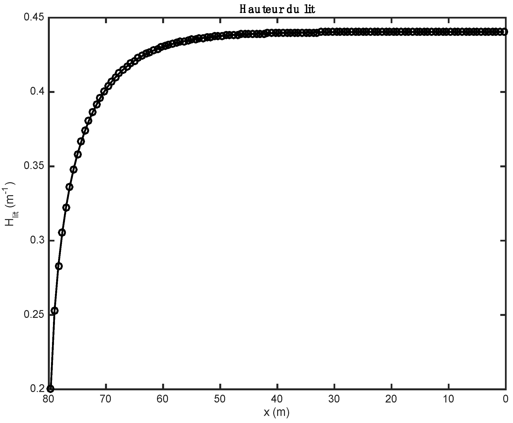
The height of the bed has a considerable influence on the heat flows in the rotary kiln. It is greatly influenced by the diameter of the kiln, the dynamic angle of the kiln, the inclination of the kiln, and the speed of rotation of the kiln.
The variation in fuel flow influences not only the height of the bed, but also the heat exchanges in the kiln.
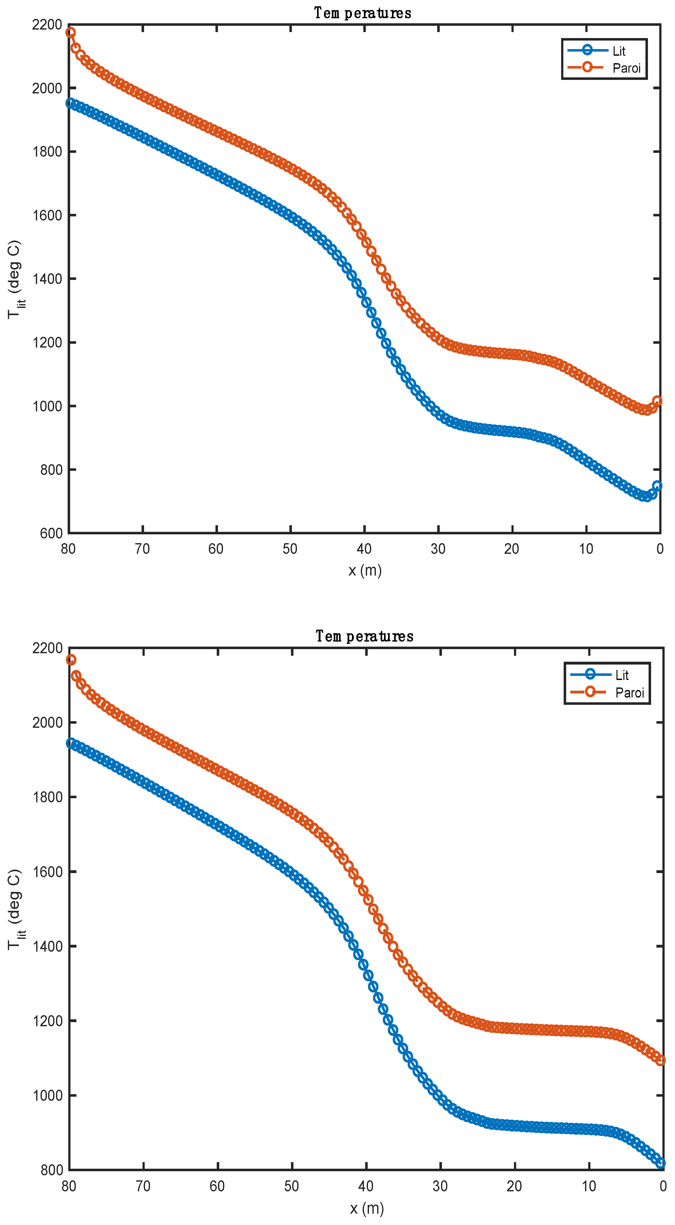
The temperature profiles are strongly influenced by the heat of reaction of the alternative fuel used.
The value of this stoichiometric coefficient associated with the value of the heat of reaction allows for a good understanding of the evolution profiles of the composition of the waste.
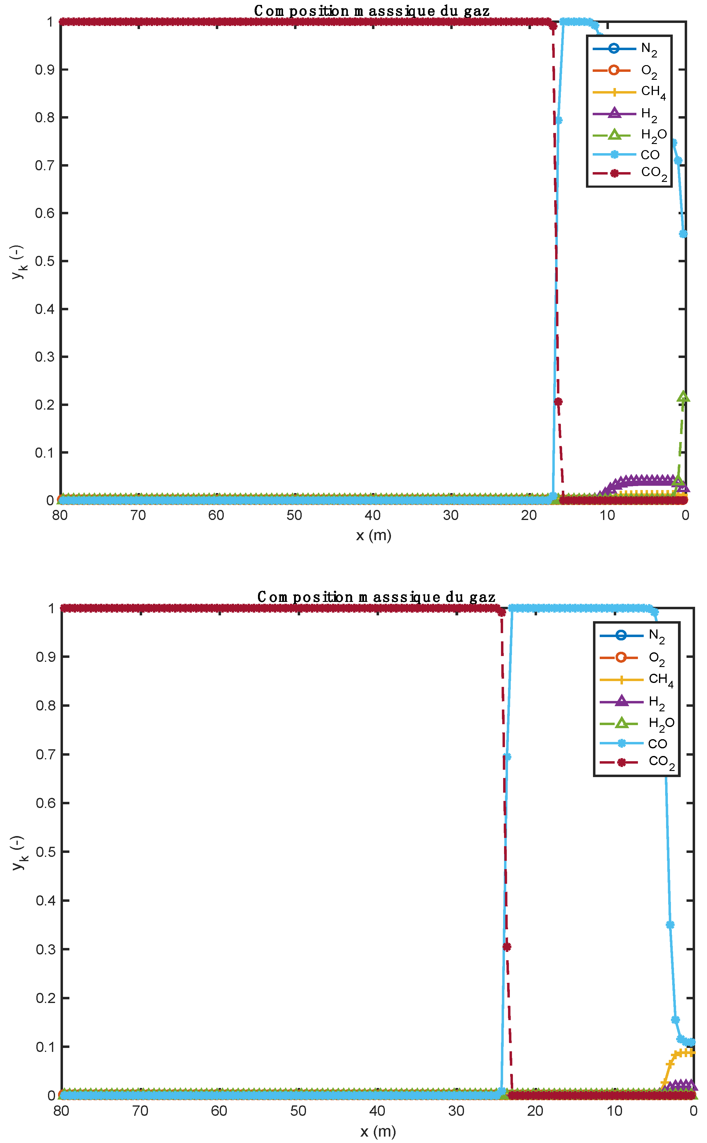
The end of the gasification stage is marked by a change in the composition of the gas from CO to CO2.
The use of biomass is accompanied by an optimal conversion of C2S to C3S, that is, 52.36%.
The interception angle of the bed is related to the diameter of the kiln.
The endothermic pyrolysis of biomass allows an optimal consumption of lime (CaO) formed by the decomposition reaction of CaCO3.
The main originality of this study is the establishment of a complex numerical model of thermochemical transformation of wastes, coupled with the clinkering process.
In another sense, this article has exposed the different potential paths of the scientific community devoted to the use of alternative fuels in the context of cement production. Thermochemical phenomena occur in the kiln, and the effects of the operating parameters and materials properties of alternative fuels are currently being studied in order to obtain the best cement clinker. Future research will focus on the influence of ash composition from alternative fuels on cement production. Future work should also focus on the total substitution of waste in cement rotary kilns, where 50% of the energy input would come from the combustion of waste in the bed of solids, and the other 50% from the combustion of solid waste at the kiln burner. This will make it possible for industries to move away from dependence on fossil energy sources that are deemed to be polluting.

Author Contributions

Conceptualization, B.-J.R.M.B. and F.M.; Methodology, B.-J.R.M.B. and F.M.; Software, B.-J.R.M.B. and F.M.; Validation, B.-J.R.M.B.; Investigation, B.-J.R.M.B.; Writing–original draft, B.-J.R.M.B. and F.M; Supervision, B.-J.R.M.B. and F.M. All authors have read and agreed to the published version of the manuscript.

Funding

This research received no external funding.

Data Availability Statement

The data presented in this study are available on request from the corresponding author.

Acknowledgments

The authors would like to thank the Thermal, Energetic and Processes Laboratory (LaTEP) of the University of Pau (France) for funding the publication of this research work. They thank also the Futuris Research Institute (InReF) of the Democratic Republic of The Congo for the provision of the research framework.

Conflicts of Interest

The authors declare no conflict of interest.

Nomenclature

List of Symbols
A b e d Transverse surface of the bed[m2]
A Pre-exponential factor[s−1]
d k i l n Diameter of rotary kiln[m]
E a Activation energy [J·mol−1]
e r e f r a c Refractory thickness [m]
h b e d Enthalpy of the bed [J·kg−1]
H b e d Bed height [m]
h Heat exchange coefficient[W·m−2·K−1]
k Speed constant[s−1]
l b e d Width of the bed[m]
L k i l n Kiln length[m]
M i Molar mass of the species i[kg mol−1]
m ˙ Mass flow[kg·s−1]
N z Number of waste particles[m−1]
n k i l n Speed of rotation of the kiln[tr·s−1]
q v Volume flow rate [m3·s−1]
r Chemical reaction rate[kg·m−2·s−1]
R k F a , F a Specific net rate of production/disappearance of k species of meal[kg·m−3·s−1]
R q d e c , d e c Specific net rate of production/disappearance of species q of waste [kg·m−3·s−1]
R b g a s , g a s Specific net rate of production of species b associated with the homogeneous reactions in the gas phase [kg·m−3·s−1]
R b f a , g a s Specific net rate of production of species b by the decomposition reactions of meal[kg·m−3·s−1]
R b d e c , g a s Specific net rate of production of species b gas by decomposition reactions of waste.[kg·m−3.s−1]
S surface[m2]
S t r a n s Cross-sectional area of the kiln wall[m2]
[ i ] Molar/mass concentration
T Temperature [K]
u Speed [m·s−1]
x Axial direction of the kiln (kiln length in m)
y k f a Mass fraction of k species in meal (flour)[-]
y f a b e d Mass fraction of the flour in the bed[-]
y q d e c Mass fraction of species q in waste[-]
y d e c b e d Mass fraction of waste in the bed[-]
y b g a s Mass fraction of species b in gas[-]
y g a s b e d Mass fraction of gas in the bed[-]
Greek Letters
δ k i l n Tilting of the kiln[rad]
δ b e d Angle of interception of the bed[rad]
ε Emissivity [-]
λ Thermal conductivity[W·m−1·K−1]
ρ Volume mass [kg·m−3]
φ d y n Dynamic angle of repose of the bed[rad]
φ Heat exchange flow[W]
ω Angular velocity[rad·s−1]
Subscripts and Superscripts
0 Initial condition/kiln inlet
a s h e s Ashes
C h a r , p y r o Char pyrolysis
d e c Waste
c o u v Covered
d e c o u v Uncovered
e x t Outside environment
f a Meal
k i l n Kiln or wall of the kiln
f r e e Free
f r e e , b e d Freeboard gas-bed of solids
k i l n , b e d Covered wall of the kiln–bed of solids
k i l n , e x t Outer wall of the kiln–outside environment
g a s Gas
g a s F B Freeboard gas
h u m Humidity
b e d Bed of solids
O r g . M a t . Organic matter
Cement Notations
CCaO: Calcium oxide or lime
SSiO2: Silicon dioxide or Silica
AAl2O3: Alumina
FFe2O3: Iron oxide III
Abbreviations
AEAlgebraic equation
CFDComputational fluid dynamics
NCELLNumber of cellules (numerical parameter)
NESFASOLNumber of species of solid meal (flour)
NESDECNumber of species of waste (biomass)
NESGAZNumber of gas species
Translation of Certain Words (or Text) Present in Figures
French versionEnglish version
Composition massique de la farineMass composition of meal
Composition massique du déchetMass composition of waste
Composition massique du gazMass composition of gas
Hauteur du litHeight of the bed
LitBed
ParoiWall
Vitesse des gaz quittant le litGas speed leaving the bed

References

  1. Mikulčić, H.; Zhang, Z. Application of Novel Thermochemical Methods for Enhanced Synthesis of Alternative Fuels in the Period of Energy Transition. Fuel 2021, 306, 121958. [Google Scholar] [CrossRef]
  2. Xu, J.; Yu, J.; Xu, J.; Sun, C.; He, W.; Huang, J.; Li, G. High-Value Utilization of Waste Tires: A Review with Focus on Modified Carbon Black from Pyrolysis. Sci. Total Environ. 2020, 742, 140235. [Google Scholar] [CrossRef] [PubMed]
  3. Wang, S.; Dai, G.; Yang, H.; Luo, Z. Lignocellulosic Biomass Pyrolysis Mechanism: A State-of-the-Art Review. Prog. Energy Combust. Sci. 2017, 62, 33–86. [Google Scholar] [CrossRef]
  4. Zhang, Y.; Niu, Y.; Zou, H.; Lei, Y.; Zheng, J.; Zhuang, H.; Hui, S. Characteristics of Biomass Fast Pyrolysis in a Wire-Mesh Reactor. Fuel 2017, 200, 225–235. [Google Scholar] [CrossRef]
  5. Werther, J.; Saenger, M.; Hartge, E.-U.; Ogada, T.; Siagi, Z. Combustion of Agricultural Residues. Prog. Energy Combust. Sci. 2000, 26, 1–27. [Google Scholar] [CrossRef]
  6. Basile, L.; Tugnoli, A.; Stramigioli, C.; Cozzani, V. Thermal Effects during Biomass Pyrolysis. Thermochim. Acta 2016, 636, 63–70. [Google Scholar] [CrossRef]
  7. Martínez, J.D.; Puy, N.; Murillo, R.; García, T.; Navarro, M.V.; Mastral, A.M. Waste Tyre Pyrolysis—A Review. Renew. Sustain. Energy Rev. 2013, 23, 179–213. [Google Scholar] [CrossRef]
  8. Atal, A.; Levendis, Y.A. Comparison of the Combustion Behaviour of Pulverized Waste Tyres and Coal. Fuel 1995, 74, 1570–1581. [Google Scholar] [CrossRef]
  9. Singh, S.; Nimmo, W.; Gibbs, B.M.; Williams, P.T. Waste Tyre Rubber as a Secondary Fuel for Power Plants. Fuel 2009, 88, 2473–2480. [Google Scholar] [CrossRef]
  10. Oboirien, B.O.; North, B.C. A Review of Waste Tyre Gasification. J. Environ. Chem. Eng. 2017, 5, 5169–5178. [Google Scholar] [CrossRef]
  11. Ariyaratne, W.K.H.; Malagalage, A.; Melaaen, M.C.; Tokheim, L.-A. CFD Modelling of Meat and Bone Meal Combustion in a Cement Rotary Kiln—Investigation of Fuel Particle Size and Fuel Feeding Position Impacts. Chem. Eng. Sci. 2015, 123, 596–608. [Google Scholar] [CrossRef]
  12. Babler, M.U.; Phounglamcheik, A.; Amovic, M.; Ljunggren, R.; Engvall, K. Modeling and Pilot Plant Runs of Slow Biomass Pyrolysis in a Rotary Kiln. Appl. Energy 2017, 207, 123–133. [Google Scholar] [CrossRef]
  13. Mungyeko Bisulandu, B.-J.R.; Marias, F. Modeling of the Thermochemical Conversion of Biomass in Cement Rotary Kiln. Waste Biomass Valorization 2021, 12, 1005–1024. [Google Scholar] [CrossRef]
  14. Nielsen, A.R. Combustion of Large Solid Fuels in Cement Rotary Kilns. Ph.D. Thesis, Department of Chemistry, Technical University of Denmark, Kgs. Lyngby, Denmark, 2012. [Google Scholar]
  15. Marias, F.; Roustan, H.; Pichat, A. Modelling of a Rotary Kiln for the Pyrolysis of Aluminium Waste. Chem. Eng. Sci. 2005, 60, 4609–4622. [Google Scholar] [CrossRef]
  16. Pieper, C.; Wirtz, S.; Schaefer, S.; Scherer, V. Numerical Investigation of the Impact of Coating Layers on RDF Combustion and Clinker Properties in Rotary Cement Kilns. Fuel 2021, 283, 118951. [Google Scholar] [CrossRef]
  17. Kara, M. Environmental and Economic Advantages Associated with the Use of RDF in Cement Kilns. Resour. Conserv. Recycl. 2012, 68, 21–28. [Google Scholar] [CrossRef]
  18. Gao, N.; Kamran, K.; Quan, C.; Williams, P.T. Thermochemical Conversion of Sewage Sludge: A Critical Review. Prog. Energy Combust. Sci. 2020, 79, 100843. [Google Scholar] [CrossRef]
  19. Jiang, G.; Xu, D.; Hao, B.; Liu, L.; Wang, S.; Wu, Z. Thermochemical Methods for the Treatment of Municipal Sludge. J. Clean. Prod. 2021, 311, 127811. [Google Scholar] [CrossRef]
  20. Kleppinger, E.W. Cement Clinker: An Environmental Sink for Residues from Hazardous Waste Treatment in Cement Kilns. Waste Manag. 1993, 13, 553–572. [Google Scholar] [CrossRef]
  21. Tsiliyannis, C.A. Alternative Fuels in Cement Manufacturing: Modeling for Process Optimization under Direct and Compound Operation. Fuel 2012, 99, 20–39. [Google Scholar] [CrossRef]
  22. Mokrzycki, E.; Uliasz-Bocheńczyk, A. Alternative Fuels for the Cement Industry. Appl. Energy 2003, 74, 95–100. [Google Scholar] [CrossRef]
  23. Zabaniotou, A.; Theofilou, C. Green Energy at Cement Kiln in Cyprus—Use of Sewage Sludge as a Conventional Fuel Substitute. Renew. Sustain. Energy Rev. 2008, 12, 531–541. [Google Scholar] [CrossRef]
  24. Kolesnikova, O.; Syrlybekkyzy, S.; Fediuk, R.; Yerzhanov, A.; Nadirov, R.; Utelbayeva, A.; Agabekova, A.; Latypova, M.; Chepelyan, L.; Volokitina, I.; et al. Thermodynamic Simulation of Environmental and Population Protection by Utilization of Technogenic Tailings of Enrichment. Materials 2022, 15, 6980. [Google Scholar] [CrossRef] [PubMed]
  25. Kolesnikova, O.; Vasilyeva, N.; Kolesnikov, A.; Zolkin, A. Optimization of Raw Mix Using Technogenic Waste to Produce Cement Clinker. Min. Inf. Anal. Bull. 2022, 60, 103–115. [Google Scholar] [CrossRef]
  26. Lopez, G.; Alvarez, J.; Amutio, M.; Mkhize, N.M.; Danon, B.; van der Gryp, P.; Görgens, J.F.; Bilbao, J.; Olazar, M. Waste Truck-Tyre Processing by Flash Pyrolysis in a Conical Spouted Bed Reactor. Energy Convers. Manag. 2017, 142, 523–532. [Google Scholar] [CrossRef]
  27. Chen, L.; Dupont, C.; Salvador, S.; Grateau, M.; Boissonnet, G.; Schweich, D. Experimental Study on Fast Pyrolysis of Free-Falling Millimetric Biomass Particles between 800 °C and 1000 °C. Fuel 2013, 106, 61–66. [Google Scholar] [CrossRef] [Green Version]
  28. Mujumdar, K.S.; Ranade, V.V. Simulation of Rotary Cement Kilns Using a One-Dimensional Model. Chem. Eng. Res. Des. 2006, 84, 165–177. [Google Scholar] [CrossRef]
  29. Patisson, F.; Lebas, E.; Hanrot, F.; Ablitzer, D.; Houzelot, J.-L. Coal Pyrolysis in a Rotary Kiln: Part I. Model of the Pyrolysis of a Single Grain. Metall. Mater. Trans. B 2000, 31, 381–390. [Google Scholar] [CrossRef] [Green Version]
  30. Patisson, F.; Lebas, E.; Hanrot, F.; Ablitzer, D.; Houzelot, J.-L. Coal Pyrolysis in a Rotary Kiln: Part II. Overall Model of the Furnace. Metall. Mater. Trans. B 2000, 31, 391–402. [Google Scholar] [CrossRef] [Green Version]
  31. Ginsberg, T.; Modigell, M. Dynamic Modelling of a Rotary Kiln for Calcination of Titanium Dioxide White Pigment. Comput. Chem. Eng. 2011, 35, 2437–2446. [Google Scholar] [CrossRef]
  32. Lybaert, P. Contribution à l’étude Du Transfert de Chaleur Entre Un Matériau Particulaire et La Paroi Dans Les Échangeurs Rotatifs Indirects. Ph.D. Thesis, Faculté Polytechnique de Mons, Mons, Belgium, 1985. [Google Scholar]
  33. Darabi, P. A Mathematical Model for Cement Kilns. Ph.D. Thesis, University of British Columbia, Vancouver, BC, Canada, 2007. [Google Scholar]
  34. Mungyeko Bisulandu, B.-J.R. Modélisation de l’apport d’énergie par Combustibles Alternatifs dans les Fours Tournants de Production de Ciment. Ph.D. Thesis, Université de Pau et des Pays de l’Adour, Pau, France, 2018. [Google Scholar]
  35. Arthur, J.R. Reactions between Carbon and Oxygen. Trans. Faraday Soc. 1951, 47, 164. [Google Scholar] [CrossRef]
  36. Cooper, J.; Hallett, W.L.H. A Numerical Model for Packed-Bed Combustion of Char Particles. Chem. Eng. Sci. 2000, 55, 4451–4460. [Google Scholar] [CrossRef]
  37. Hallett, W.; Green, B.; Machula, T.; Yang, Y. Packed Bed Combustion of Non-Uniformly Sized Char Particles. Chem. Eng. Sci. 2013, 96, 1–9. [Google Scholar] [CrossRef]
  38. Matsumoto, K.; Takeno, K.; Ichinose, T.; Ogi, T.; Nakanishi, M. Gasification Reaction Kinetics on Biomass Char Obtained as a By-Product of Gasification in an Entrained-Flow Gasifier with Steam and Oxygen at 900–1000 °C. Fuel 2009, 88, 519–527. [Google Scholar] [CrossRef]
  39. Bernada, P.; Marias, F.; Deydier, A.; Couture, F.; Fourcault, A. Modelling of a Traveling Bed WASTE Gasifier. Waste Biomass Valorization 2012, 3, 333–353. [Google Scholar] [CrossRef]
  40. Marias, F.; Benzaoui, A.; Vaxelaire, J.; Gelix, F.; Nicol, F. Fate of Nitrogen during Fluidized Incineration of Sewage Sludge. Estimation of NO and N2O Content in the Exhaust Gas. Energy Fuels 2015, 29, 4534–4548. [Google Scholar] [CrossRef]
  41. Marias, F.; Puiggali, J.-R. Simulation Numérique d’un Brûleur Industriel. Analyse Qualitative Des Effets de Swirl Sur l’écoulement et Sur La Production de Polluants. Int. J. Therm. Sci. 2000, 39, 249–264. [Google Scholar] [CrossRef]
  42. Nørskov, L.K. Combustion of Solid Alternative Fuels in the Cement Kiln Burner. Ph.D. Thesis, Technical University of Denmark, Kgs. Lyngby, Denmark, 2012. [Google Scholar]
  43. Kohlhaas, B.; Labahn, O. Cement Engineers Handbook, 6th ed.; Bauverlag GMBH: Berlin, Germany, 1983; ISBN 3-7625-0975-1. [Google Scholar]
  44. Csernyei, C.; Straatman, A.G. Numerical Modeling of a Rotary Cement Kiln with Improvements to Shell Cooling. Int. J. Heat Mass Transf. 2016, 102, 610–621. [Google Scholar] [CrossRef]
  45. Mastorakos, E.; Massias, A.; Tsakiroglou, C.D.; Goussis, D.A.; Burganos, V.N.; Payatakes, A.C. CFD Predictions for Cement Kilns Including Flame Modelling, Heat Transfer and Clinker Chemistry. Appl. Math. Model. 1999, 23, 55–76. [Google Scholar] [CrossRef]
  46. Pongo Pongo, C. Caractéristiques Des Produits Cinat, Cimenterie Nationale, Kimpse, 2012.
  47. Spang, H.A. A Dynamic Model of a Cement Kiln. Automatica 1972, 8, 309–323. [Google Scholar] [CrossRef]
  48. Lixhe CBR. Fiche Technique-Usine de Lixhe; Cimenteries Belges Réunifiées: Liège, Belgium, 2012. [Google Scholar]
Figure 1. Evolution of the height of the bed along the axis of the kiln.
Recycling 08 00041 g001
Figure 2. Comparison of gas composition profiles obtained with two alternative fuels (above: biomass; below: tires).
Recycling 08 00041 g002
Figure 3. Comparison of gas velocity profiles obtained with two alternative fuels (above: biomass; below: tires).
Recycling 08 00041 g003
Figure 4. Comparison of the temperature profiles obtained with two alternative fuels (above: biomass; below: tires).
Recycling 08 00041 g004
Figure 5. Comparison of waste composition profiles obtained with two alternative fuels (above: biomass; below: tires).
Recycling 08 00041 g005
Figure 6. Comparison of the temperature profiles obtained with 30 (above) et 120 (below) compute nodes (heavy fuel oil and biomass).
Recycling 08 00041 g006
Figure 7. Comparison of the meal composition profiles obtained with 30 (above) et 120 (below) compute nodes (heavy fuel oil and biomass).
Recycling 08 00041 g007
Figure 8. Comparison of the gas velocity profiles obtained with 30 (above) et 120 (below) compute nodes (heavy fuel oil and biomass).
Recycling 08 00041 g008
Figure 9. Meal composition profiles comparing current predictions to those in the literature [28,44,47].
Recycling 08 00041 g009
Table 1. Model equations.
EquationNumber
d d z ρ b e d A b e d u b e d y f a b e d y k f a = A b e d R k F a , F a (1)
d d z ρ b e d A b e d u b e d y f a b e d = A b e d k = 1 N E S F A S O L R k F a , F a (2)
d d z ρ b e d A b e d u b e d y d e c b e d y q d e c = A b e d R q d e c , d e c (3)
d d z ρ b e d A b e d u b e d y d e c b e d = A b e d q = 1 N E S D E C R q d e c , d e c (4)
d d z ρ b e d A b e d u b e d y g a s b e d y b g a s = A b e d R b g a s , g a s + R b d e c , g a s + R b f a , g a s ρ g a s u g a s l b e d y b g a s (5)
d d z ρ b e d A b e d u b e d y g a s b e d = A b e d b = 1 N E S G A Z R b d e c , g a s + R b f a , g a s ρ g a s u g a s l b e d (6)
d d z ρ b e d A b e d u b e d = ρ g a s u g a s l b e d (7)
d d z ρ b e d A b e d u b e d h b e d = ρ g a s u g a s h g a s l b e d + φ f r e e , b e d l b e d + φ k i l n , b e d δ b e d d k i l n (8)
h b e d = y f a b e d h f a + y d e c b e d h d e c + y g a s b e d h g a s (9)
1 ρ b e d = y f a b e d ρ f a + y d e c b e d ρ d e c + y g a s b e d ρ g a s (10)
δ b e d z s i n δ b e d z = 8 A b e d z d k i l n 2 (11)
l b e d z = d k i l n s i n δ b e d z 2 (12)
A b e d = 1 2 d k i l n 2 δ b e d z l b e d z . d k i l n 2 H b e d z (13)
d H b e d z d z = t g φ d y n . t g δ k i l n s i n φ d y n 6 q v π n k i l n d k i l n 3 H b e d z d k i l n 4 H b e d 2 z d k i l n 2 3 2 (14)
q v ( z ) = A b e d z u b e d ( z ) (15)
λ k i l n S t r a n s d 2 T k i l n d z 2 = 2 π δ b e d d k i l n 2 φ f r e e , k i l n δ b e d d k i l n 2 h k i l n , b e d T k i l n T b e d + π d k i l n + 2 e r e f r a c h e x t T e x t T k i l n (16)
Table 2. Variables of the 1D model of the bed of solids.
VariablesMeaningQuantityUnit
y k S o l Mass fraction of species k in solid meal NESFASOL-
y f a b e d Mass fraction of meal in the bed 1-
y q d e c Mass fraction of species q in the waste NESDEC-
y d e c b e d Mass fraction of waste in the bed 1-
y b g a s Mass fraction of species b in the bed gas NESGAZ-
y g a s b e d Mass fraction of gas in the bed 1-
ρ b e d Bed density 1kg·m−3
T b e d Bed temperature 1K
h b e d Bed enthalpy 1J·kg−1
u b e d Bed speed 1m·s−1
H b e d Bed height 1m
u g a s Gas velocity leaving the bed to the freeboard1m·s−1
With NESFASOL = 11, NESDEC = 4, and NESGAZ = 13.
Table 3. Characteristics of meal at the inlet end of kiln and of its operation.
ParameterValue
Characteristics of meal
Mass flow of meal at the inlet of kiln (t/h)175
Mass composition of meal (-)
CaCO30.1111
Al2O30.0488
SiO20.2005
Fe2O30.0378
CaO0.5599
MgO0.0419
Inlet temperature of meal (°C)800
Void fraction of meal at the inlet of kiln (%)20
Dynamic angle of repose of the bed (°)30
Characteristics of the rotary kiln
Length (m)80
Inside diameter of the kiln (m)4
Kiln rotation speed (rpm)2
Angle of inclination of the kiln (°)2
Thermal conductivity of the kiln wall (W·m−1·K−1)0.1
Table 4. Proximate and ultimate analyses of waste considered in the present model [34].
BiomassTires
Proximate Analysis (% Raw material)
Moisture 6.90.0
Organic Matter92.795.1
Inorganic (ashes)0.34.9
Proximate Analysis (% Dry material)
Organic Matter99.6895.1
Inorganic (ashes)0.324.9
Ultimate Analysis (% Dry ash-free)
C49.284.3
H6.07.7
O44.314.7
N0.50.8
S0.022.5
Cl0.00.00
Lower calorific Value (MJ/kg, Raw material)17.236.2
Table 5. Homogeneous reactions in the gas phase [34].
ReactionsRate [mol/m3/s]A (SI)Ea [J/mol]
H2 + 0.5O2→H2Ok1[O2]·[H2]1.080 × 1071.255 × 105
CO + 0.5O2→CO2k2[CO]·[O2]0.25·[H2O]0.51.780 × 10101.800 × 105
CO + H2O→CO2 + H2k3[CO]·[H2O]2.778 × 10−11.256 × 104
CO2 + H2→CO + H2Ok4[CO2]·[H2]1.263 × 1014.729 × 104
CH4 + 2O2→CO2 + 2H2Ok5[CH4]−0.3·[O2]1.31.300 × 1052.025 × 105
CH4 + 0.5O2→CO + 2H2k6[CH4]0.7·[O2]0.81.580 × 10122.026 × 105
CH4 + H2O→CO + 3H2k7[CH4]·[H2O]3.101 × 1001.247 × 105
C6H6 + 3O2→6CO + 3H2k8[C6H6]·[O2]1.580 × 10122.026 × 105
C6H6 + 7.5O2→6CO2 + 3H2Ok9[C6H6]−0.1·[O2]1.856.324 × 1061.255 × 105
Table 6. Main operating characteristics of the burner.
ParameterDarabi [33]Nørskov [42]Present Model
Mass flow of heavy fuel oil at the burner (kg/s)2.71673.904.27
Injection temperature of heavy fuel oil (°C)60100100
Mass flow of spray air (kg/s)6.9540.821.01
Spray air temperature (°C)92100100
Mass flow rate of primary air (kg/s)6.5163.275.52
Primary air temperature (°C)92100100
Mass flow of secondary air (kg/s)14.34636.842.68
Secondary air temperature (°C)8491000800
Table 7. Proximate and ultimate analyses of the heavy fuel oil used in the area of Lukala.
Proximate Analysis (% Raw Material)Darabi [33]Nørskov [42]Present Model
Moisture1.240.640.0
Organic Matter89.2196.5799.968
Inorganics9.552.790.032
Proximate Analysis (% Dry material)
Organic Matter90.3397.1999.968
Inorganics9.672.810.032
Ultimate Analysis (% Dry ash-free)
C71.8188.2483.3
H3.734.745.2
O7.144.619.6
N1.081.491.4
S5.450.920.5
Cl0.00.000.00
Lower calorific value (MJ/kg, Raw material)26.7233.97 *33.21 *
* dry.
Table 8. Flows of fossil and alternative fuels used for partial substitution.
ParameterValue
Mass flow of heavy fuel oil at the burner (kg/s)2.26
Mass flow of biomass (kg/s)4.36
Mass flow of tires (kg/s)2.07
Table 9. Characteristics of cements obtained with two alternative fuels.
Heavy Fuel Oil + BiomassHeavy Fuel Oil + Tires
Exit BedExit Bed
Mass flow (t/h)166.5Temperature (°C)1949.7Mass flow (t/h)166.8Temperature (°C)1942.13
Cement in the bed (% in mass)99.96% Cement in the bed (% in mass)99.78%
Cement composition (% in mass)Cement composition (% in mass)
CaCO30.00%C2S20.22%CaCO30.00%C2S21.19%
Al2O30.00%C3A7.04%Al2O30.00%C3A7.04%
SiO20.24%C4AF11.79%SiO20.27%C4AF11.79%
Fe2O30.10%C3S52.36%Fe2O30.10%C3S51.00%
CaO3.83%MgCO30.00%CaO4.21%MgCO30.00%
MgO4.41% MgO4.41%
Waste in the bed (% in mass)0.36% Waste in the bed (% in mass)0.22%
Waste composition (% in mass)Waste composition (% in mass)
Ashes100%Org. Mat0.00%Ashes100%Org. Mat0.00%
Humidity0.00%Char0.00%Humidity0.00%Char0.00%
Table 10. Characteristics of the flows exchanged in the two substitution cases.
BiomassTires
S f r e e φ f r e e , b e d d S = 42.54   MW S f r e e φ f r e e , b e d d S = 40.91   MW
S d e c o u v φ f r e e , k i l n d S = 30.89   MW S d e c o u v φ f r e e , k i l n d S = 31.33   MW
S c o u v φ k i l n , b e d d S = 13.69   MW S c o u v φ k i l n , b e d d S = 13.79   MW
Table 11. Simulation error.
Clinker SpeciesDarabi [33]Present Model
(Heavy Fuel Oil + Biomass)
Present Model
(Heavy Fuel Oil + Tires)
Gap
C2S11%20.22%21.19%−9.22 to 10.19
C3A9.50%7.04%7.04%2.46
C4AF8.00%11.79%11.79%−3.79
C3S64.00%52.36%51.00%11.64 to 13
CaCO30.00%0.00%0.00%0.00
CaO2.00%3.83%4.21%−1.83 to −2.21
Disclaimer/Publisher’s Note: The statements, opinions and data contained in all publications are solely those of the individual author(s) and contributor(s) and not of MDPI and/or the editor(s). MDPI and/or the editor(s) disclaim responsibility for any injury to people or property resulting from any ideas, methods, instructions or products referred to in the content.

