Article

Impact of Spheroidization of Natural Graphite on Fast-Charging Capability of Anodes for LIB

1
Institute for Particle Technology, Technische Universität Braunschweig, Volkmaroder Str. 5, 38104 Braunschweig, Germany
2
Battery LabFactory Braunschweig, Technische Universität Braunschweig, Langer Kamp 19, 38106 Braunschweig, Germany
3
Netzsch Trockenmahltechnik GmbH, Rodenbacher Ch 1, 63457 Hanau, Germany
*
Author to whom correspondence should be addressed.
Batteries 2023, 9(6), 305; https://doi.org/10.3390/batteries9060305
Submission received: 2 May 2023 / Revised: 25 May 2023 / Accepted: 29 May 2023 / Published: 1 June 2023

Abstract

:
Despite numerous research on new active materials for anodes, graphite remains the most commonly used material in Li-ion batteries. The spherical shape of the graphite particles has proven to be beneficial for application in electric vehicles, especially for fast charging. So far, the spheroidization of natural flake graphite is conducted by a rigid and inefficient cascade process. In this work, a scalable classifier system was used for spheroidization, and it was demonstrated that a spheroidization time of 15 min is sufficient to improve material properties and enhance electrochemical performance while maintaining high process yields of 55%. Insights into the influence of the morphology on the intrinsic and structural properties of the graphite particles and manufactured electrodes are provided. Spheroidization creates a more efficient pore network in the coating layer while reducing the internal resistance and increasing the surface area of the particles by a factor of 1.8. We demonstrate that the spherical shape improves the discharge rate capability by 1.8, and the specific charge capacity could be enhanced by more than 237% at a C-rate of 3. An additional carbon coating could significantly decrease the specific surface area and increase the specific capacity at high C-rates.

1. Introduction

Lithium-ion batteries (LIBs) are the most widely used battery type in electric vehicles (EVs) and play an essential role in the success of the transport sector’s electrification. The high demand for rechargeable LIBs for steady, portable, and automotive applications results in extensive research on active materials for cathodes and anodes [1,2,3]. Despite the availability of alternative materials [4,5,6,7], graphite is still the most common active material for anodes because of its flat discharge curve, low cost, non-toxicity, high first-cycle efficiency, and cycle stability [8,9,10,11]. Li-ions can intercalate between the graphite layers, forming lithium–graphite intercalation compounds, which exhibit a theoretical gravimetric capacity of 372 mAh g−1 [2]. However, the morphology of graphite restrains the intercalation of the Li-ions because the ions can only access the graphite layers from the sides [12,13,14]. Therefore, fast charging capability is limited, which is an important factor for EVs. For automotive applications, a reduced charging time of LIBs is required to be comparable to refueling an internal combustion engine vehicle. Companies such as Battrion AG with the Aligned Graphite® Technology develop processes to increase the charge and discharge performance of battery cells by improving the microstructure of negative electrodes [12].
Natural flake graphite (NFG) occurs in a layered structure consisting of prismatic platelets inside rocks. Moreover, the structure is divided into basal and edge planes [2,12,13]. Due to different dimensions in the parallel and vertical directions (anisotropy), a uniform distribution of the flake graphite on the current collector foil is difficult. The graphite particles have a preferred orientation on the current collector with the basal plane surface perpendicular to the current flow [2,14]. Since inter-/deintercalation of Li-ions occurs through edge plane surfaces, the rate capacity of NFG is poor [15]. Additionally, the morphology affects the surface area and reactivity with the electrolyte [9]. Furthermore, the level of compressibility during the calendering process is influenced by the particle shape and, therefore, the volumetric cell capacity as well [16]. Hence, the layered structure of NFG needs to be modified for application in advanced LIBs. A variety of graphite types for LIBs with different refinements (shapes, surface treatments, and coatings) are currently offered on the market [9,17]. The literature suggests various approaches to improve the intercalation rate of graphite [18,19,20,21,22,23]. Additional surface sites for intercalation are created by chemical etching or exfoliation of graphite edges with edge-selective functionalization [24,25,26]. By mechanical rolling/spheroidization of the flakes to spherical particles, an isotropic property is expected. Thus, the intercalation rate should be improved. Additionally, the spherical shape reduces the tortuosity of the electrode, which improves Li-ion diffusion. Especially for large-scale production, a complex process of comminution and refining, which depends on the graphite content and the flake size, precedes spheroidization [13,27,28]. During spheroidization, the flakes are rolled like a snowball, or the edges are shaved off by mills with different beaters on the plates, using 15 to 20 mills connected in series for large-scale production [29,30]. Various examples of graphite shaping processes in lab-scale are presented in the literature [15,23,31,32,33,34]. Guoping et al. used a self-made miller to mill NFG for 12 h and then coated the resulting spherical particles with non-graphitic carbon [35]. Flakes were rounded with a high-speed rotational dry impact mill in a lab-scale batch process by Mancini et al. [23]. Biber et al. presented a new scalable spheroidization process using an impact mill and classifier separately for a high-yield process depending on the adjusted spec. process energy [34]. Depending on the mill type, the graphite particles are stressed by impact/collision interactions when the graphite hits the wall of the grinding chamber or is impacted by balls [27,30]. In addition, graphite particles are subjected to high-shear interactions as the ball rolls against the wall of the milling vessel or between individual graphite particles, which leads to their spheroidization [30].
However, the mechanical methods for spheroidization are rigid, laborious, and exhibit a yield of only 35–50%. The yield strongly depends on the raw material, desired particle size, and application [32,33,36]. Furthermore, spheroidization using a cascading process is time-consuming and requires multiple mills. Thus, spherical graphite is costly compared to flake graphite.
Herein, we examine the influence of mechanical rounding of graphite particles in a single step using a new classifier mill (GyRHO system, developed by Netzsch GmbH in cooperation with Dorfner Anzaplan, Hirschau, Germany) on the structural and electrochemical properties in negative electrodes for LIB. The scalable system reduces the number of mills required for the spheroidization process, which cuts maintenance, space, operating, and energy costs. The system provides a solution for the spheroidization of natural graphite with a short treatment time and high yield. A detailed evaluation of the rate capacity and cycle stability of different morphologies of NFG was demonstrated. Additionally, the impact of an added pitch-derived carbon coating on the spherical surface is investigated.

2. Materials and Methods

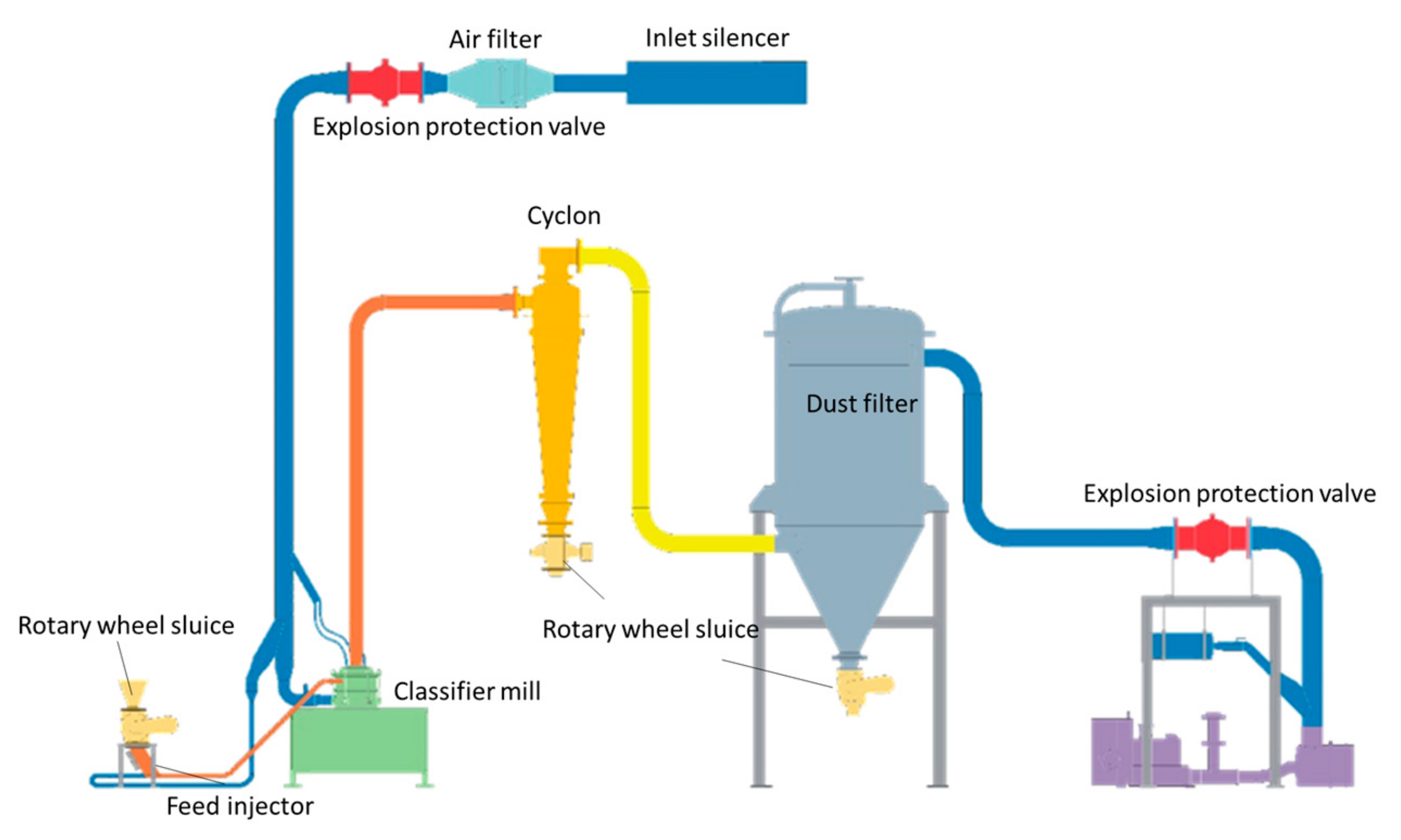
2.1. Spheroidization of NFG

Spheroidization of graphite was conducted by the GyRHO classifier system (Netzsch Trockenmahltechnik GmbH, Hanau, Germany). The system is based on the classifier mill CSM 165, which combines a mechanical impact mill with an integrated dynamic deflector wheel classifier (Figure 1). At the beater rotor, the material is accelerated by the beaters and is spun against the grinding track. While fine particles are sifted by a classifier, coarser particles remain inside the chamber. Particles are rounded as soon as they are guided in the airflow of the milling chamber. The mill chamber was unloaded by opening a lid, which connects a suction unit to the chamber via a pipeline. The air and material are drawn into a separation unit consisting of a cyclone, which classifies the graphite to the final size distribution, reducing the amount of coarser graphite particles.
A natural flake graphite was used as starting material. In the first process step, the natural flake graphite (d50: 239 µm, d90: 450 µm) was comminuted to the desired initial grain size (d50: 19.55 µm, d90: 36.74 µm) for following spheroidization (Gr_flake) in the same classifier system. Subsequently, 1 kg of ground graphite was stressed and rounded in a batch process. The graphite was rounded in the time interval of 15 to 30 min (Gr15 to Gr30). Table 1 summarizes the process parameters of spheroidization. The same flake graphite was processed in the GyRHO classifier system with the scaled classifier mill CSM 360 forming a pancake-like shaped graphite (Gr_pancake). In the scaled process, a total mass of 4 kg was added. The rotational speeds are always related to the maximum speed of the specific machine. In order to study the influence of spheroidization and treatment times in detail and directly correlate them with the electrochemical performance, no further surface modification is performed for Gr15 to Gr30. However, Gr15 was also surface modified by a pitch-derived carbon coating (named Gr15cc in the following). HSP pitch from China Steel Chemical Corporation (Taiwan, China) was applied on the surface of the spherical graphite particles. The coating process is described elsewhere and was applied here [37].

2.2. Graphite Powder Characterization

Graphite particle size changes during the spheroidization process were conducted with an LA-960V2 Laser Particle Size Analyzer from Horiba Ltd.,Kyoto, Japan. The graphite was diluted in deionized water, and the particle size distribution was measured. Scanning electron microscopy (SEM) images of the graphite particle morphology were taken by a Helios G4 CX from FEI Deutschland GmbH, Dreieich, Germany. Measurements of the powder’s electrical conductivity were conducted within a test chamber of non-conductive polytetrafluoroethene by Zwick Z020 material testing machine from ZwickRoell GmbH, Ulm, Germany [38,39]. A compressing stamp made of brass compressed the powder against a brass bottom. The maximum compression pressure during the measurement was 3.54 MPa (400 N on 1.13 cm2). A constant current of 0.1 mA was concurrently applied, and the resulting voltage was recorded by a Resistomat 2329 from Burster GmbH & Co KG, Gernsbach, Germany. The electric conductivity is the inverse of the electrical resistance, which was calculated by Ohm’s law [40]. Influences of the morphology on the specific surfaces were determined by measuring the adsorption isotherms according to BET. The measurement was performed by a NOVA 2000e Surface Area & Pore Size Analyzer from Quantachrome Instruments, Boynton Beach, FL, USA.

2.3. Electrode Production and Physical Characterization

The different graphite materials were processed into electrode slurries by a Dispermat CA60 dissolver from VMA Getzmann GmbH, Reichshof, Germany. At first, graphite, the binder carboxyl methyl cellulose (Texturecel™ 2000 PA from IFF, Oegstgeest. The Netherlands; CMC), and the conductive additive Super C65 (C-NERGY Super C65 from Imerys Graphite and Carbon, Bodio, Switzerland) were dry mixed for 15 min at 49 rpm by a shaker mixer Turbula T-2-F from Willy Bachofen AG, Switzerland, to obtain a homogeneous mixture. The mixed powders were added to deionized water, forming 600 mL slurries, and dispersed for 45 min with a tangential speed of the dissolver of 9 m s−1. In the next step, the second binder styrene–butadiene rubber (BM-451B from Zeon Corporation, Tokyo, Japan; SBR) was added, and the slurries were additionally dispersed and degassed for 10 min at 3 m s−1. The solid mixture of graphite, carbon black (Super C65), and binders CMC and SBR were dispersed in a weight ratio of 93/1.4/2.1/3.5 wt.% in the aqueous slurry, respectively. The solids content of the electrode slurry was set to 45 wt.%. The slurries were then coated on a copper foil (Furukawa Electric, Tokyo, Japan) with a thickness of 10 µm by the pilot scale coating and drying line LabCo from Kroenert GmbH & Co KG, Hamburg, Germany [41]. Negative electrodes with a width of 170 mm and a dry mass loading of 8.96 mg cm−2 (3 mAh cm−2) were produced. The coating speed was set to 1 m min−1, resulting in a residence time of 6 min in the convection dryer (three segments of 2 m each). The first two segments had a temperature profile of 65 °C, and the third one was 100 °C.
The cathode was manufactured in the same way as the anode. Instead of an aqueous solution, the material was dispersed in N-methyl-2-pyrrolidone (BASF Corp., Global City, Philippines, NMP). The cathode was made of NCM 622 (BASF, Ludwigshafen, Germany), PVdF 5130 (Solvay Solexis S.A.S, Houston, TX, USA), and Carbon Black Super C65 (C-NERGY Super C65 from Imerys Graphite and Carbon, Switzerland). Weight ratio of NCM/PVdF/CB was 94/3/3 wt.%, and the solids content of the electrode slurry was 60 wt.%. Cathodes with a mass loading of 16.9 mg cm−2 (3 mAh cm−2) on aluminum foil were manufactured.
By calendering, the coating of the anode and cathode were compressed by a GKL 400 calender from Saueressig, Germany, to densities of 1.5 g cm−3 and 3.0 g cm−3, respectively.
The adhesive strength σn and electronic conductivity of the electrodes were measured by a pull-off test in the material testing machine Z020 from Zwick GmbH. The electrodes were punched into 12 mm diameter disks and fixed between two plane-parallel plates with the help of double-sided adhesive tape (tesafix 5696 extra strong, Tesa SE, Norderstedt, Germany) for the adhesive strength measurement as described by Haselrieder et al. [42]. The plates were pressed on each other with a maximum force of 68 N for 30 s. Subsequently, the sample holders were torn apart with a speed of 100 mm min−1, and consequently, the coating was torn off the substrate. The maximum tensile force Ft, max of the coating was detected, and adhesion strength σn was calculated using σn = Ft, max/A. Ten samples of each anode were measured and averaged. The electric conductivity of the electrodes was measured by the determination of the voltage drop of a continuous current percolating the electrode in z-dimension. The method is described by Westphal et al. [38,40].
Porosity measurements were performed by mercury intrusion within a mercury porosimeter PoreMaster 60 (Quantachrome Instruments Ltd.). The principle and applied method are described by Froboese et al. [43]. For interpretation of the results, pore diameters ranging from 10 nm to 40 µm were analyzed due to the maximal graphite particle diameter.

2.4. Electrochemical Characterization

For electrochemical characterization, the graphite anode and cathode sheets were assembled into pouch cells. Three pouch cells were built from each graphite variation (Gr15–Gr30, surface refined Gr15cc, and Gr_pancake), as well as from the flake graphite. The specific capacity of graphite and NCM 622, 360 mAh g−1 and 186 mAh g−1, respectively, were used to calculate the capacity of the individual electrodes (~87 mAh for anodes, ~72 mAh for cathodes). LP57 (1M LiPF6 in EC/EMC (3:7 wt.%)) + 2% vinylene carbonate (VC) was used as the electrolyte and a commercial three-layer laminated separator. The cycling tests were performed at room temperature (20 °C) in a Maccor 4000 series battery tester. The cells were initially charged in constant current (CC) mode. Afterward, charging in constant current constant voltage (CCCV) mode was conducted, which prevented the cell from being overcharged. Furthermore, the cells were discharged at different C-rates (0.1, 0.5, 1, 2, 3) while they were charged with 0.1 C. Subsequently, the cells were charged with various C-rates (0.1, 0.5, 1, 2, 3) and discharged at 0.1 C. For a long-term stability test, 50 cycles at 1 C were performed and repeated four times. After every 50 cycles, the initial capacity was queried again at 0.1 C.

3. Results

3.1. Spheroidization of Natural Flake Graphite

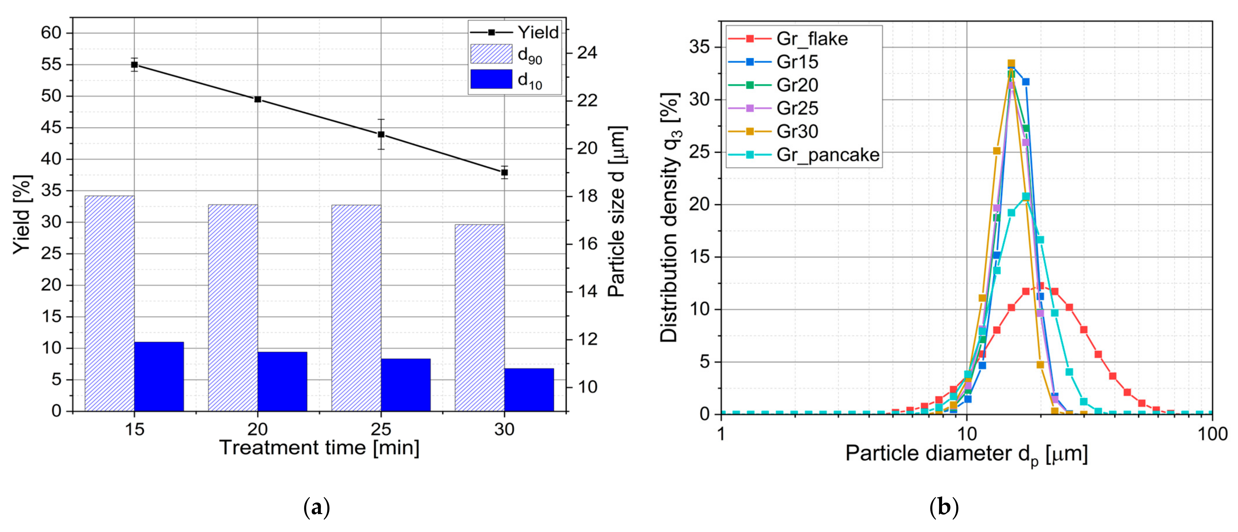
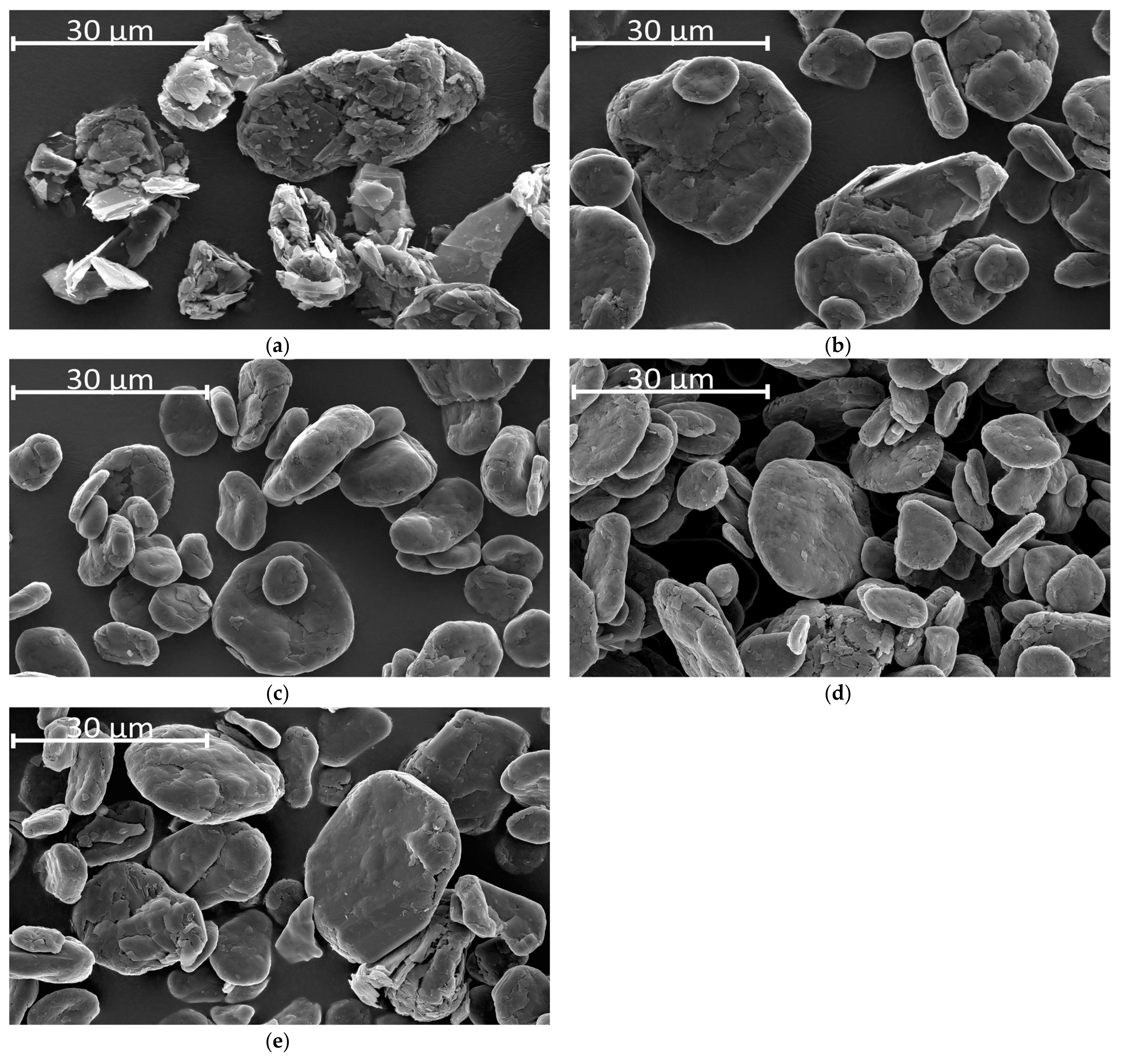
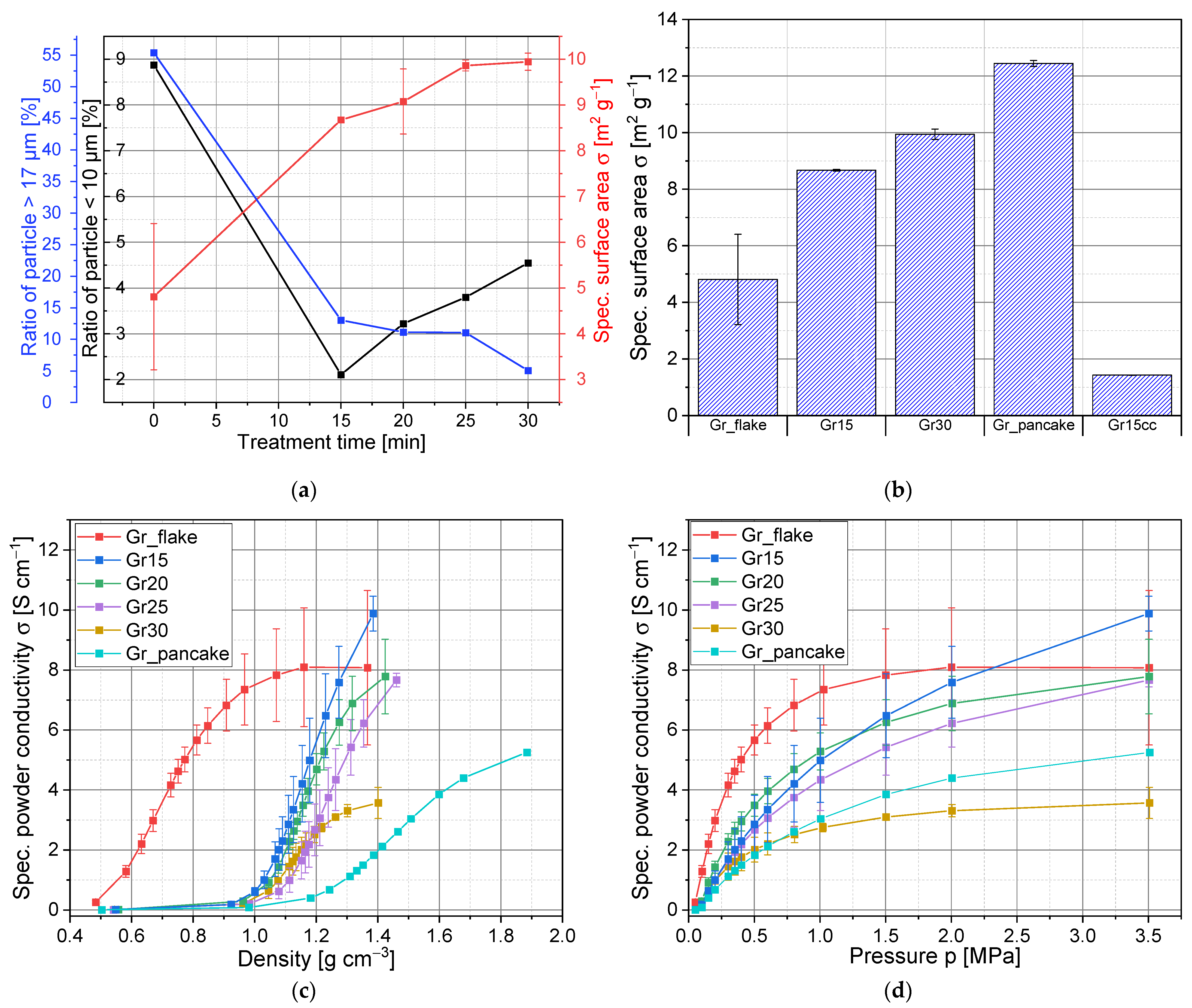
3.1.1. Graphite Particle Characterization

NFG was treated by the GyRHO system from Netzsch in a scalable spheroidization process. During stressing the NFG in the classifier system, the graphite flakes were formed into rounded particles by impact. Product quality and the intrinsic properties of the spheroidized graphite were characterized by different criteria. The spherical graphite is compared with the natural graphite starting material (Gr_flake) and the shaped pancake morphology (Gr_pancake). Figure 2a illustrates the yield of the spheroidization process for different treatment times. While the other operating parameters stayed the same, the yield declined with increasing treatment time. A treatment time of 15 min results in a yield of 55%. After 30 min, the yield reduces to 38%. With higher treatment times, the amount of smaller particles rises. Smaller graphite particles for the demanded product particle size of 8 µm < d < 36 µm are screened out of the system by the internal classifier wheel, reducing the overall yield. Gr_pancake in the up-scaled CSM 360 results in a yield of 14% after 20 min and requires further optimization. Characteristic particle sizes d90 and d10 slightly decrease over time (Figure 2 and Table S1). However, the particle size distribution remains nearly constant for the different treatment times (Figure 2b). The sharpness of the particle size distribution can be characterized by the ratio of (d90 − d10)/d50. The (d90 − d10)/d50-ratio remains nearly constant at 0.43 over time due to the same operating parameters of the classifier and the cyclone (Table S1). Gr_flake has a broad particle size distribution with 1.36 and a d90-value of 36.74 µm. The sharpness of the particle size distribution is increased by spheroidization and classification. In general, the spheroidization of the graphite flakes results in a decrease of the average particle size by 5 µm and by nearly 50% of the d90-value. A sharp particle size distribution with a high yield is conclusively obtained after 15 min. The pancake-shaped graphite particles exhibit a broader particle size distribution with 0.69 and a slightly increased mean particle size. While the d10-value stays the same, the d90-value increases to 21.42 µm (Table S1).
SEM images illustrate the spheroidization of graphite. Figure 3a–d provide an optical comparison between the spherical samples, the flake graphite, and the Gr_pancake. The NFG has clear edges and shows the natural flake-like structure of graphite (Figure 3a). SEM images of the rounded graphite show distinct morphological changes (Figure 3b,c). The particles exhibit a more rounded shape and a much smoother surface with increasing treatment time. While edges are still present after 15 min, they disappear with increased treatment time. Cracks and step-like undulations are visible on the surface of the spherical particles in Figure S1a in the Supplementary Materials. Gr_pancake particles evince more of a pancake-like morphology than a potato-like shape. Edges were rounded by the comminution process as well, and a plane surface was observed. Thus, the spheroidization process eliminated the edges of the graphite flakes and formed rounded particles. Smaller flakes could be distinguished to a low extension on the surface and were most likely due to renewed attachment of graphite fragments onto the surface of larger spherical particles. After 30 min, the flake character of the graphite was no longer evident, and the graphene layers were rounded on the surface (Figure S1b).
The increasing treatment time of the graphite particles resulted in an increase in the specific surface area of graphite (Figure 4a). While a smaller specific surface area with more spherical particles is expected, the opposite trend is observed. Biber et al. also determined a higher surface area of their rounded graphite particles depending on the applied process energy [34]. Figure S2 illustrates the link between the volumetric specific surface area, which is calculated by the mean particle size, and the measured specific surface area. A correlation with the decreasing mean particle size can be determined. Fine particles have a larger specific surface area and the possibility to reattach onto coarser particles. While the ratio of particles greater 17 µm decreases and the ratio of spherical graphite particles smaller 10 µm increases, the specific surface area increases at the same time. Figure 4a shows the link between the ratio of particles <10 µm and >17 µm and the specific surface area. Although Gr_flake has the highest proportion of larger particles, the proportion of particles smaller than 10 µm is also high. The result is a smaller specific surface area than the spheroidized graphite particles. After 30 min of spheroidization, the surface area has more than doubled in comparison to the NFG. This is a result of an interaction between the ratio of small particles and the formation of new micropores and cracks caused by the spheroidization process. Mundzinger et al. [32] determined an increase in the proportion of open pores accessible to nitrogen molecules by evaluating FIB tomograms. New pores and cracks were created due to rounding and an increase in energy impact. Cracks within the spherical graphite particles coated with an internal SEI film were also located by Zhang et al. [44]. Newly created pores result in higher adsorption of nitrogen molecules and, thus, a greater specific surface area. The specific surface area of the pancake-shaped graphite is 12.5 m2 g−1 (Figure 4b) and significantly higher compared to spherical graphite. In addition to the particle ratio and inner porosity, the morphology of the graphite particles also influences the specific surface area [9]. The different spheroidization processes and operation times result in an increase in the specific surface area of the graphite particles (Figure 4b).
The intrinsic properties of graphite were further investigated by measuring the electric powder conductivity as a function of density or pressure, respectively (Figure 4c,d). With increased pressure and, thus, increased compression, the electric powder conductivity of graphite increases (Figure 4d). At the same time, the packing density of the graphite rises (Figure 4c). Flake graphite (Gr_flake) shows significantly higher conductivity at lower densities than spherical graphite particles. For the spherical graphite, the conductivity increases significantly with increasing density, whereas the change in density is relatively low. Essentially, the conductivity increases with greater contact areas between the particles. Parameters such as particle shape, interfacial forces between particles, electron transport mechanism, and packing density have a significant influence on the contact areas between particles [45,46]. Heo et al. described electrical conductivity by two mechanisms: inter-particle conductivity and intra-particle conductivity [46]. Since Gr_flake is a planar flake graphite, wider surface-to-surface contact points are formed. Spherical graphite particles generally form point-to-point contacts rather than surface-to-surface contacts. In the first compression stage, the density is controlled by the rearrangement and fragmentation of agglomerates. A second stage is determined by the elastic and plastic deformation of the particles [45]. Gr_flake converges, and the contact areas become greater when it is compressed under high pressure. The high compression pressure causes individual graphite flakes to break, refold, and compress, thereby increasing the density. A higher density of graphite leads to higher electrical conductivity because conductive paths are shorter (inter-particle conductivity) [47]. Conduction by point-to-point interfaces of the rounded graphite particles (Gr15–Gr30) limits inter-particle conductivity. The decrease in electrical conductivity with increasing treatment time occurs due to the stability of the spherical graphite particles. The graphite particles become rounder and smaller, resulting in a more stable shape. Particles deform less with increasing compression and remain connected by point-to-point interfaces. A higher line load for calendering with a minimal roller gap of 25 µm exhibits the rising stability of the particles in Table S2. The spherical graphite particles become more stable with increasing treatment time, and the force to deform increases. The density of the coating layer was limited to ~1.91 g cm−3 for spherical graphite; flake graphite reached a coating density of 2.02 g cm−3. Point-to-point interfaces due to the shape and increased mechanical stability are the reason for inhibition of the electron transfer with the spherical graphite material. However, the smaller and more spherical graphite particles generate a closer packing at low pressure and, therefore, a higher density in comparison to the coarser graphite flakes (Figure S3 and Figure 4c). Electrodes with Gr_pancake require a lower line load for a density of 1.9 g cm−3 with the minimal roller gab. Due to their pancake-like shape, the particles can rearrange and be compressed more easily with less force.

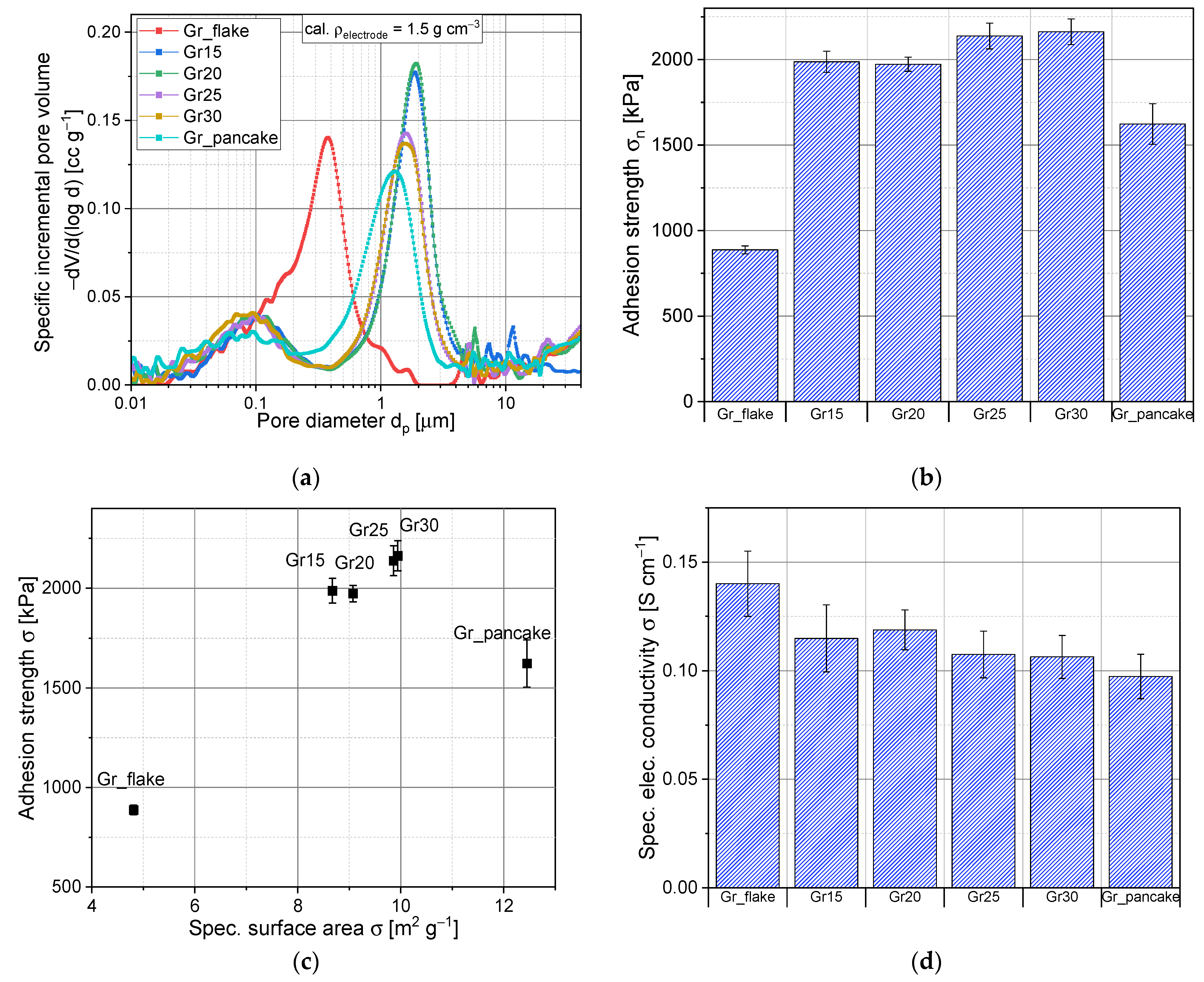
3.1.2. Anode Structure Characterization

As the intrinsic properties influence the electrochemical performance of electrodes, anodes of the different graphite materials were produced and analyzed. In the first step, the manufactured graphite anodes were characterized with regard to their structural and mechanical properties. All negative electrodes were calendered to a density of 1.5 g cm−3.
Figure 5a illustrates the logarithmic pore size distributions of the calendered anodes. Gr15 to Gr30 exhibit a bimodal distribution, while Gr_flake shows only one peak. The first peak at 2 µm is characteristic of pores between graphite particles and larger internal pores of graphite, which are not or partially filled with CB agglomerates [40,48]. The second peak (<1 µm) especially represents pores inside the network of binder and carbon black and between carbon black particles. Flake graphite particles form a coating layer with smaller pores than the spherical graphite material (Figures S3 and S4). The density of the flake graphite coating before calendaring is significantly lower compared to the spherical graphite (Table S3). It illustrates that the flake graphite takes up a greater volume than spherical particles before calendering but forms a dense layer with smaller pores at the same line load. A difference can be seen for the different treatment times of Gr15/Gr20 and Gr25/Gr30. Gr25/Gr30 have a smaller pore volume between 1 and 2.4 µm, and the second peak is shifted to a smaller pore diameter. Binder and carbon black can attach better and form a denser layer because the graphite particles are rounder. Spheroidization creates new pores, as previously described, which are not present in the NFG [32,44,49]. The flakes are folded by impact grinding, which allows the formation of new pores between the folded graphite layers. Increasing the treatment time ensures that individual graphene layers are firmer compressed and individual pores are closed. Overall, the spheroidization results in the formation of a significant amount of coarser pores that were not present in NFG anodes. Gr_pancake exhibits a bimodal pore volume distribution as well. The peak between graphite particles and internal pores is further shifted to 1.3 µm, and the amount of smaller pores is reduced. The porosity has a strong influence on electrical and ionic conductivity [50].
While the specific surface area influences the initial capacity loss, a high adhesion strength is beneficial for handling in production and cycle stability [51]. The adhesion strength of the coating is significantly enhanced by the spherical and pancake morphology (Figure 5b). With increasing treatment time and accordingly increasing rounding of the graphite particles, the adhesive strength clearly increased. The calendered anode made of flake graphite has an adhesion strength of 887 kPa; rounded graphite has 2.5 times, Gr_pancake a 2 times higher adhesion. During electrode processing, the bond strength is mainly developed by crosslinking the binder in the drying process, forming a polymer binder matrix. Thus, a strong binder matrix can be formed much better by a spherical or pancake-shaped morphology than by flake-like particles. In the electrode layer, SBR is mainly responsible for the adhesive force between the coating and the current collector [51,52,53]. CMC ensures a high cohesive force between the particles [53]. Graphite with a smooth surface has a higher adsorption capacity for the nonpolar SBR due to hydrophobic interactions [53]. Binding to the smooth graphite surface and repulsive forces of water causes SBR to be more stationary and concentrate close to the current collector foil. The surface of the spherical and pancake-shaped graphite material is significantly smoother and offers a greater specific surface area for the formation of hydrophobic interactions with SBR, as illustrated in Figure 4a,b and SEM images Figure 3a,d. Figure 5c shows the link between adhesion strength and specific surface area. A greater specific surface area provides more binding sites for the binder and, thus, an increase of the adhesion strength. While the adhesion strength was enhanced by a spherical or pancake-like morphology, the electrical conductivity was reduced (Figure 5d). In general, the conductivity decreased compared to the graphite powder conductivity due to the insulating binder network. Changes in the treatment time had no effect on the electrical conductivity of the coating layer. Thus, a uniform network of graphite particles and carbon black was formed, which is practically independent of the degree of spheroidization and determined by the binder-carbon black-network. The differences in the powder conductivity, shown in Figure 4c,d, were mostly eliminated during dispersion, coating and calendering of the graphite. NFG anodes show a slightly higher conductivity.

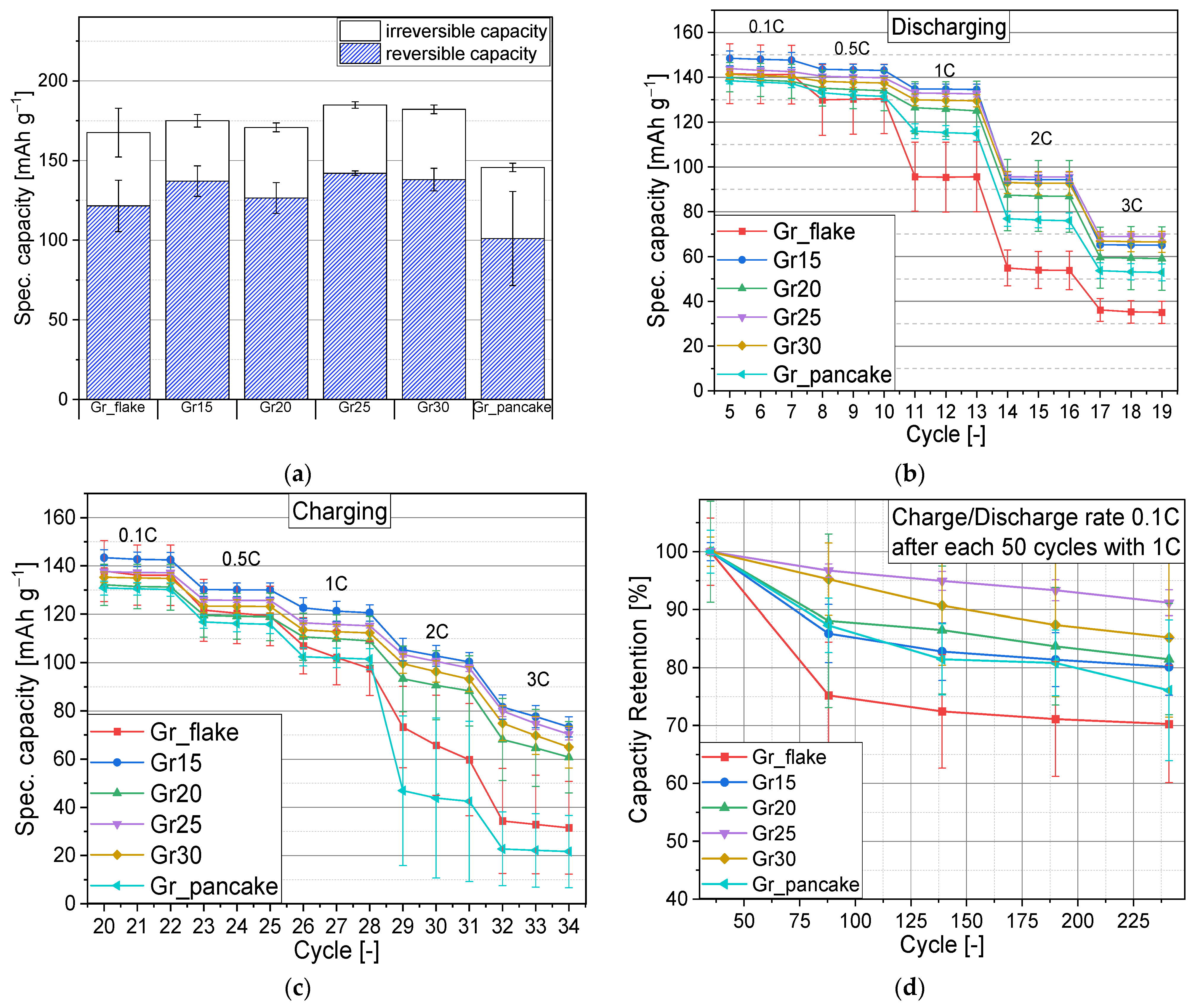
3.1.3. Electrochemical Characterization of Spheroidized Graphite

Graphite particles with various morphologies and treatment times were characterized regarding their electrochemical performance in a pouch full-cell configuration with an NCM cathode. Discharge and charge capacities at different current rates and cycle stability were examined. The average of three pouch cells was used for further discussion. The measured electrochemical differences are only dependent on the graphite material because the cathode, separator, electrolyte, and cell configuration were kept the same. The irreversible and reversible capacities of the pouch cells during the formation cycle are given in Figure 6a. In the first charging step, the cells made of NFG reach a capacity of 167 mAh g−1 (referring to the cathode). Due to the formation of a passivation layer and exfoliation of the graphite layers, the irreversible capacity is 46 mAh g−1. Cells with spherical graphite anodes (Gr15–Gr30) have a first discharge capacity of ≈178 mAh g−1 and a capacity loss of 42 mAh g−1; thus, an initial reversible specific capacity of 127 to 142 mAh g−1 is obtained. Pouch cells of Gr_pancake reach an initial specific capacity of 101 mAh g−1. During the formation cycle, lithium reacts with the electrolyte forming a passivating layer on the surface of the graphite particles, so-called solid electrolyte interface (SEI) [54,55]. Formation of the SEI results in a rise of the irreversible capacity (decrease of the Coulombic Efficiency (CE)). Gr15 to Gr30 had a CE of 74–78% of the first cycle, which is higher than the 72.7% of Gr_flake. Porosity and specific surface have a strong effect on the formation of the SEI layer and the irreversible capacity loss [50,56]. While the bigger pores (>1 µm) of the anodes decrease with increasing treatment time, the specific surface area of the graphite particles increases at the same time. Therefore, a similar CE and reversible capacity of Gr15–Gr30 in the first cycle is observed. In addition to the increased surface area of the spherical graphite, the described cracks and pores formed during the spheroidization allow the electrolyte to penetrate into the active material [32,44]. The penetrating electrolyte can decompose, forming an internal SEI and thereby irreversibly consume lithium ions [44]. A certain porosity is required for wetting the electrode surface and forming a uniform and stable SEI layer. However, an excessively high porosity can increase the surface area available for SEI formation, resulting in thicker and less uniform SEI layers. This leads to increased irreversible capacity due to higher irreversible reactions during charge and discharge cycles. A pancake-like shape reduces the CE to 68%. Gr_pancake particles provide a greater specific surface area for the formation of an SEI layer. Thus, more Li-ions are consumed, and the irreversible capacity increases.
The rate capability for charging and discharging was further investigated by variation of specific current, as shown in Figure 6b,c. Mean specific capacities of the cathodes are illustrated, as the cathode capacity was the limiting factor. At low C-rates, there is no significant difference detected between the cells with different graphite morphologies. The cells show a similar specific capacity in the range between 137 and 148 mAh g−1 at 0.1 C. At current rates higher than 1 C, the flake graphite suffered from fast capacity loss. After 3 cycles at 3 C, the electrode experiences a loss of more than 75%. Spherical graphite retains 42–47% of its initial capacity at 3 C. Significant loss at higher discharge currents with flake graphite has been previously reported [23,57]. Especially at high C-rates, the cells clearly lose capacity due to kinetic limitations. In anodes with a flake structure, the Li-ions can only intercalate via the edge planes. Therefore, the intercalation is limited due to the mostly horizontal alignment of basal planes parallel to the copper foil. The round morphology enhances the intercalation and deintercalation of the Li-ions in and out of the graphite and increases the charge/discharge rate [23,35,57]. The basal planes of spherical graphite exhibit a random orientation, which is why the diffusion resistance of Li ions is lower and more active material is utilized. In addition, the high measured adhesion strength of the electrode coating ensures good stability at high C-rates. The volume change during intercalation is cushioned by the matrix of binder and active material and prevents the exfoliation of graphite fragments. In general, no difference can be seen for the differently rounded graphite. This is also visible in the galvanostatic charge/discharge voltage profiles of the electrodes (Figure S5a–f). While the different treatment times show no influence, the morphology has a strong effect on the overpotential. This shows that sufficient rounding was already achieved after 15 min. Spheroidization demonstrated a significant effect on improving the rate capability of the battery cells and, thus, is a beneficial process step.
In the subsequent charging C-rate test, a decline within one C-rate is visible, as shown in Figure 6c. The electrodes of Gr_flake were irreversibly damaged by the stress at high current rates. Spheroidization improves the electrochemical properties of the anode material. The higher adhesive strength can serve as an explanation, which increases the stability of the electrode during volume expansion. While the capacity loss starts at 1 C for the pristine material, it occurs only within the charge at 2 C for the rounded graphite materials. The pancake shape has a similar behavior as the flake graphite. At high charging currents, the capacity fading is more pronounced. In addition to a diffusion limitation of Li-ions into the graphene layers of Gr_flake, the electrode transport is also limited. Figure S6 shows the internal resistance for the different battery cells when charged/discharged at 1 C. Gr_flake cells have a significantly higher internal resistance compared to the other materials, which exhibit a further positive effect of spheroidization. Thus, an opposite trend to the dry electrodes in Figure 5c,d is observed. While Gr_flake exhibits a higher electric conductivity, the NFG anodes show a higher internal resistance. The spherical graphite seems to develop a more uniform graphite-carbon black network reducing the electrical resistance. Further analysis is required to confirm this. No influence is detected between the rounded graphite. Gr_pancake exhibits a similar internal resistance as spherical graphite. A spherical morphology demonstrates a profound impact on improving cycle stability and capacity retention. The specific capacity at 0.1 C was measured after the rate capability test and after every 50 cycles during the long-term stability test with 1 C (Figure 6d). Cells with spherical graphite as active material retained between 80–92% of the specific capacity after 200 cycles. Gr_pancake lost over 24%. Gr_flake exhibited accelerated capacity fading after the first 50 cycles and lost 30% of its total initial capacity after the 200 cycles. A spherical morphology demonstrates a profound impact on improving cycle stability and capacity retention.

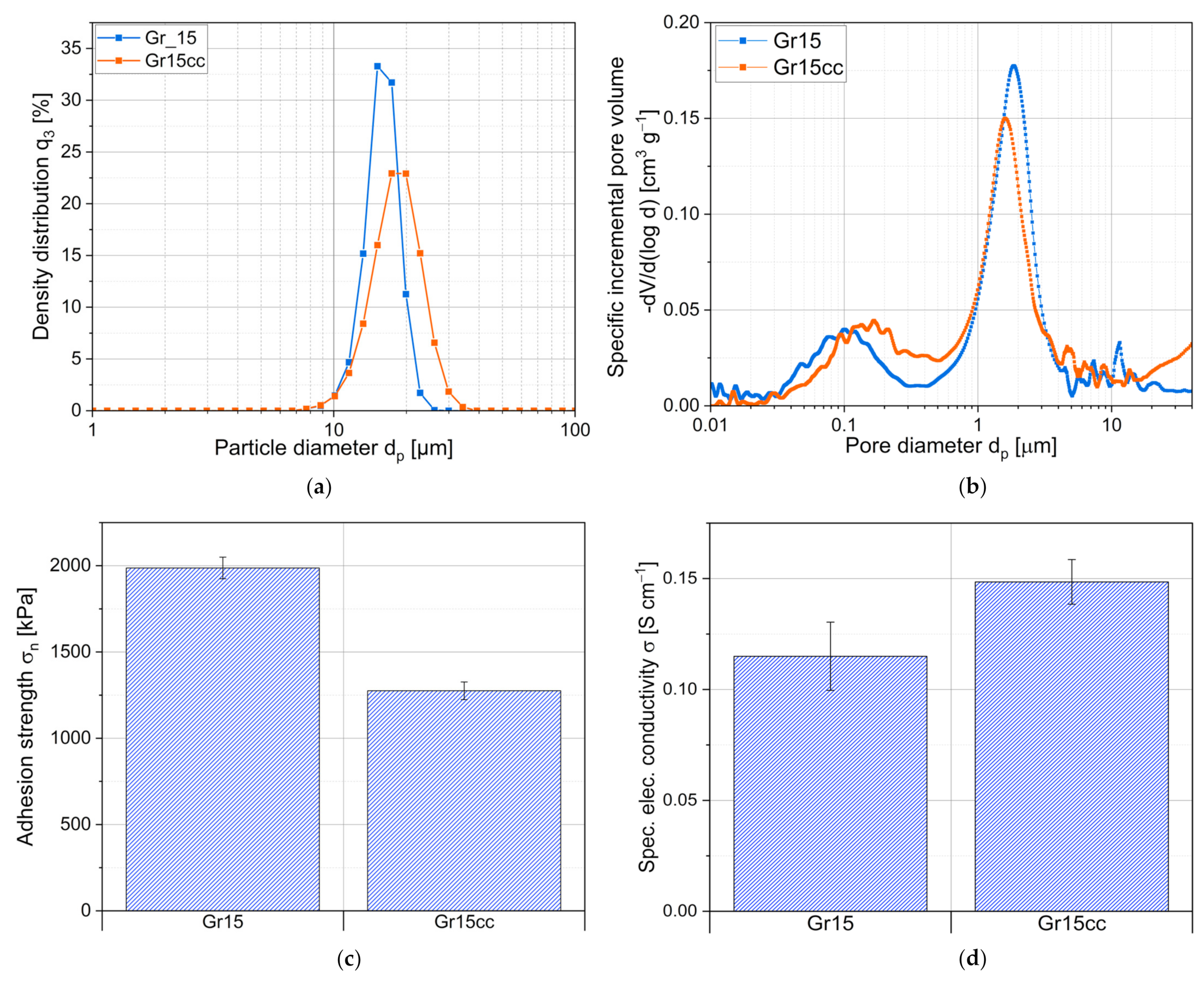
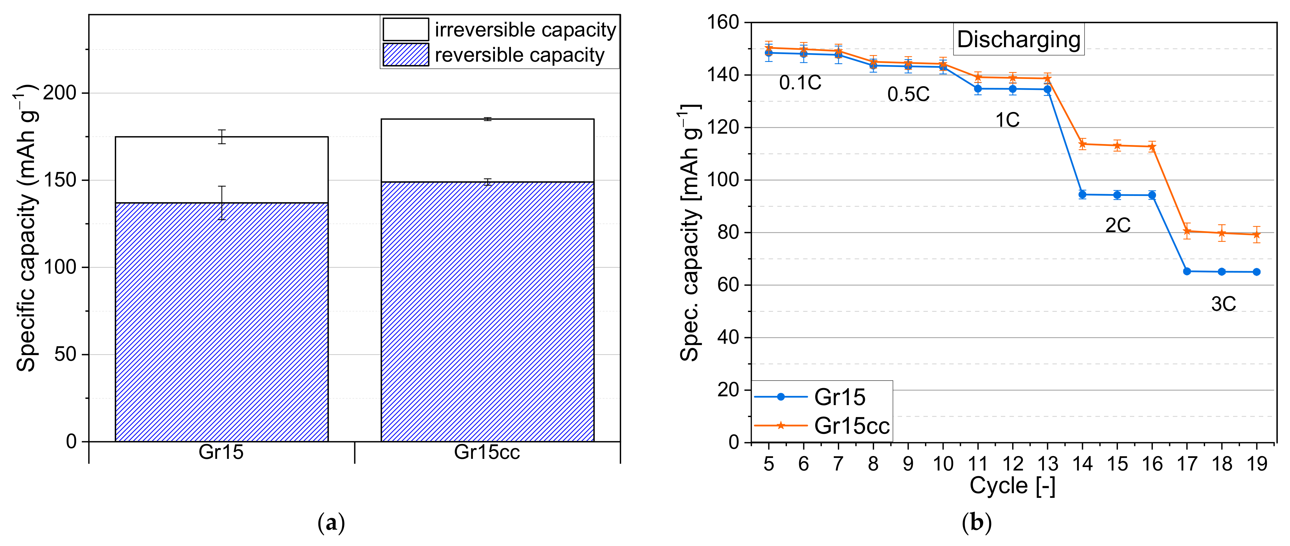
3.2. Surface Refinement of Spherical Graphite

As more intensive spheoridization by longer treatment times had no remarkable effect on the electrochemical performance of the anodes, Gr15 was further refined with a carbon coating in order to reduce the specific surface area and improve the electrochemical performance. Hence, a reduced capacity loss due to SEI formation and protection of the graphite core from exfoliation is expected.
Graphite and pitch particles were mixed and subsequently calcinated at 900 °C, as described in 2. Materials and Methods. Particle size distribution and average particle size of Gr15cc are shifted towards higher particle diameters. The refinement increases the median particle diameter by 17.06%; d10 rises by 4.12% due to the additional carbon layer (Table S1). Overall, a broader particle size distribution is obtained, as seen in Figure 7a. An increase of 0.41 to 0.60 for the (d90 − d10)/d50-ratio is determined. However, the process of carbonization has no influence on the spherical morphology of graphite particles, as illustrated in Figure 3e. The surface of the carbon-coated particles appears to be smoother, but the outer morphology could be retained. An effect of the additional coating on the specific surface area of the spherical graphite can be seen in Figure 4b. The specific surface area of Gr15cc is reduced by 83.5%. The smaller BET surface area of Gr15cc can be attributed to the blockage of some micropores on the surface by the additional carbon layer. Figure 7b exhibits the reduction of micropores of Gr15cc. According to our expectations, a shift of the peaks is detected. Most of the pores in a scale of 34 to 63 nm are closed by the carbon coating, and a shift of the peak from pore diameter of 1.9 µm to 1.5 µm is observed. Also, the amount of pores greater than 2 µm is reduced. The additional layer inhibits mercury from intruding into the cracks and inner core of the particles by closing existing pores and reducing structure defects. Ding et al. [56] and Guoping et al. [35] also observed a decreasing surface area when graphite particles were carbon-coated by CVD or a layer of nongraphic carbon in a solvent. Additionally, the spherical shape and the carbon coating strengthen the stability of the single particles. In the case of calendaring, anodes of Gr15 without a coating layer exhibit a density of 1.92 g cm−3 at a roller gap of 25 µm (line load 323.9 N mm−1), Gr15cc electrodes have a significantly smaller coating density with 1.67 g cm−3 (line load 308.3 N mm−1). The additional coating strengthens the particles, and a higher line load is needed to compress the coating to the same density (Table S3).
Mechanical properties of the manufactured graphite anodes are illustrated in Figure 7c,d. Adhesion of the spherical, pitch-coated graphite was reduced by 36% in comparison to Gr15. The higher line load of Gr15cc (160 N mm−1 compared to 62 N mm−1 for Gr15) indicates higher shear and normal stresses on the electrode in the roller gap (Table S3). This leads to particularly high stress at the interface between the electrode materials. Thus, the coating layer is stretched, which damages and/or separates the binder substrate contacts and reduces the adhesion strength [58]. While the adhesion strength of the coating layer is reduced, the electrical conductivity is improved (Figure 7d). Carbon coating enhances the electrical conductivity of the conductive network [59].
Figure 8a presents the initial charge–discharge capacities of Gr15 and Gr15cc. The observed differences are only dependent on the additional carbon coating of the graphite material because the cathode, separator, electrolyte, and cell configuration were kept the same. Gr15cc has a higher initial reversible capacity than spherical graphite without carbon coating (Gr15). The refinement increases the reversible capacity by 10 mAh g−1 (Figure 8a). Initial irreversible capacity is dependent on the specific surface area of the graphite particles since the SEI covers the active material surface area that is wetted by the electrolyte [56]. The carbon layer removes active sites for the SEI formation by reducing the specific surface area of the graphite particles (Figure 4b). Additionally, the formation of an internal SEI is hindered by the blockage of pores on the graphite surface (Figure 7b). Electrolytes can easily penetrate into the cracks of Gr15 particles and decompose to form an SEI layer, which irreversibly consumes lithium-ions. The pitch coating of Gr15cc blocks the penetrating paths, protects the graphite surface from direct contact with the electrolyte, and reduces the irreversible capacity [56,60,61]. Hence, the decomposition of the electrolyte on the surface is suppressed and acts as a protective layer against exfoliation. The non-significantly increasing, reversible capacity could indicate that the coating decreases the lithium storage ability of the graphite anode. Ding et al. described that a thick carbon layer decreases the discharging capacity of the electrode due to a limitation of the lithium storage places [56].
All cells were successively cycled under various specific currents and subsequently at a constant specific current for evaluating rate capability and cycling stability, as shown in Figure 8b,c. For the coated, spherical active material, a slightly enhanced specific capacity of 150 mAh g−1 is measured compared to the uncoated Gr15. At low discharging rates, all cells can be discharged with almost 100% of the initial capacity. At higher discharging currents (>1 C), Gr15cc exhibits an increased specific capacity. This is also illustrated in the charge/discharge voltage profiles in Figures S5b and S6. The pitch coating reduces the charge/discharge resistance. The specific capacity decreases with increasing current rates due to kinetic limitations of the deintercalation [14,23]. The coating layer obviously contributes to the improvement of the rate capability. One function of the carbon layer is to prevent the graphite from exfoliation during the intercalation and deintercalation of Li-ions and the combined volume change [35]. Secondly, the electrical conductivity of the coating is improved by forming an enhanced conductive network (Figure 7d). The carbon coating enhances the electrical conductivity of the coating layer by 29%. Electrical resistance within the coating layer of Gr15cc is reduced by 26% and 30% for charging and discharging, respectively (Figure S8). At a C-rate of 3 C, Gr15cc cells show more than 23% higher delithiation capacity than Gr15. At low charging rates, the stored capacity of the cells was slightly lower compared to the discharging rates. Starting from the charging current of 2 C, Gr15-cells showed a loss of cycling stability with decreasing capacity values. The capacity of Gr15cc-cells also declined with a higher charging rate but exhibited a higher cycle stability. During long-term cycling with a capacity request (0.1 C) after every 50 cycles, all electrodes demonstrated capacity fading. (Figure 8d). A spherical graphite shape improved the cycle stability to 80% of the initial capacity. The spherical, pitch-coated graphite further improved the compatibility of the anode with the electrolyte and acted as a protective layer against exfoliation during volume change. Hence, better cycle stability is observed, retaining 90% of the specific capacity after 200 cycles. The pitch-coating and spherical shape result in improved capacity retention of the pouch cells. The lower charging capacity at high C-rates can be a reason for a lower ionic conductivity. Additional carbon coating on the graphite particles can reduce the charge capacity at high C-rates due to limitations and Li-ion diffusion [62]. While the carbon coating improves conductivity and stability, it can inhibit the diffusion of lithium ions within the graphite particle, especially at high charge or discharge currents. The carbon coating adds a layer of non-active material on the graphite surface, which effectively reduces the available intercalation space reducing the capacity of the cell. Optimizing the amount of carbon coating can combine the benefit of an additional carbon layer with the spherical shape.
In conclusion, a better understanding of the influence of morphology on the mechanical and electrochemical properties of graphite is presented. A scalable, semi-batch process for spheroidization of NFG is shown and optimized regarding treatment time. This represents a significant basis for future graphite optimization in largescale production, in particular with further refinement for fast-charging and long-term stability.

4. Conclusions

In this study, it was demonstrated that the morphology of graphite has a significant impact on electrochemical and mechanical properties of anodes. The GyRHO system successively produced spherical natural graphite particles with a high yield in a short treatment time of 15 min and a narrow particle size distribution, suitable for LIB anodes. The spheroidization influences the graphite properties such as density, surface area, and powder conductivity. Spherical graphite anodes exhibit better electrochemical performance (especially rate capacity and cycle and long-term stability) than NFG since the diffusion resistance is reduced and adhesion strength is improved. The full cells with refined graphite show a higher lithiation capacity by a factor of 2 at 3 C than non-spherical graphite anodes. By pitch-coating of spherical graphite, enhanced stability at high current rates is observed. Overall, this study presents a large-scale, semi-batch process operation for the spheroidization of graphite, which improves material and electrochemical properties and advances the understanding of the morphological changes of graphite on the performance. Therefore, the shown data provide a basis for further development of fast-charging LIB anodes with high cycle stability.

Supplementary Materials

The following supporting information can be downloaded at: https://www.mdpi.com/article/10.3390/batteries9060305/s1, Table S1: Characteristic particle diameter dp of graphite material; Figure S1: SEM image of surface of (a) Gr15 and (b) Gr30; Figure S2: Link between volumetric specific surface area and mass-specific surface area; Table S2 Calendering of anodes with minimal roller gap (25 µm); Figure S3 Density of graphite powder vs. pressure during compression; Figure S4 Total distribution of electrode porosity of different particle morphologies; Table S3 Calendering of anodes to a density of 1.5 g cm−3; Figure S5 Galvanostatic charge/discharge voltage profiles of (a) Gr_flake; (b) Gr15; (c) Gr20; (d) Gr25; (e) Gr30; and (f) Gr_pancake composite electrodes; Figure S6 Internal electrical resistance during a cycle at 1 C.; Figure S7 Galvanostatic charge/discharge voltage profiles pitch-coated spherical graphite (Gr15cc) composite electrodes.; Figure S8 Internal electrical resistance during a cycle of Gr15 and Gr15cc at 1 C.

Author Contributions

Conceptualization, S.F., S.D. and J.M.; methodology, S.F., S.D. and J.M.; validation, S.F., S.D., J.M., C.H. and A.K.; formal analysis, S.F.; investigation, S.F.; resources, S.F., C.H.; data curation, S.F.; writing—original draft preparation, S.F.; writing—review and editing, S.D., J.M., C.H. and A.K.; visualization, S.F.; supervision, S.D., J.M. and A.K.; project administration, A.K.; funding acquisition, A.K. All authors have read and agreed to the published version of the manuscript.

Funding

This research was not carried out within a project. Academic personnel was paid by state funds of the Lower-Saxony. We have received financial support for the publication of this manuscript from the Open Access Publication Funds of Technische Universität Braunschweig.

Data Availability Statement

The presented data in this study are available in this manuscript and the accompanying Supplemental Materials.

Acknowledgments

Furthermore, the authors would like to thank Netzsch GmbH for the cooperation and the provision of the rounded graphite. The authors would also like to thank Fabian Tripke for performing the spheroidization experiments at Netzsch GmbH. We acknowledge support by the Open Access Publication Funds of Technische Universität Braunschweig.

Conflicts of Interest

The authors declare the following financial interests/personal relationships which may be considered as potential competing interests: Christian Höfels works for the company Netzsch Trockenmahltechnik GmbH, who sells and promotes the technology to round graphite. Christian Höfels is involved in the patent: P11230DE.

References

  1. Nitta, N.; Yushin, G. High-capacity anode materials for lithium-ion batteries: Choice of elements and structures for active particles. Part. Part. Syst. Char. 2014, 31, 317–336. [Google Scholar] [CrossRef]
  2. Asenbauer, J.; Eisenmann, T.; Kuenzel, M.; Kazzazi, A.; Chen, Z.; Bresser, D. The success story of graphite as a lithium-ion anode material—Fundamentals, remaining challenges, and recent developments including silicon (oxide) composites. Sustain. Energy Fuels 2020, 4, 5387–5416. [Google Scholar] [CrossRef]
  3. Mekonnen, Y.; Sundararajan, A.; Sarwat, A.I. A review of cathode and anode materials for lithium-ion batteries. In Proceedings of the SoutheastCon, Norfolk, VI, USA, 30 March–3 April 2016; pp. 1–6. [Google Scholar]
  4. Bresser, D.; Passerini, S.; Scrosati, B. Leveraging valuable synergies by combining alloying and conversion for lithium-ion anodes. Energy Environ. Sci. 2016, 9, 3348–3367. [Google Scholar] [CrossRef]
  5. Obrovac, M.N.; Chevrier, V.L. Alloy negative electrodes for Li-ion batteries. Chem. Rev. 2014, 114, 11444–11502. [Google Scholar] [CrossRef] [PubMed]
  6. Cabana, J.; Monconduit, L.; Larcher, D.; Palacín, M.R. Beyond intercalation-based Li-ion batteries: The state of the art and challenges of electrode materials reacting through conversion reactions. Adv. Mater. 2010, 22, E170–E192. [Google Scholar] [CrossRef]
  7. Müller, J.; Abdollahifar, M.; Vinograd, A.; Nöske, M.; Nowak, C.; Chang, S.-J.; Placke, T.; Haselrieder, W.; Winter, M.; Kwade, A.; et al. Si-on-Graphite fabricated by fluidized bed process for high-capacity anodes of Li-ion batteries. Chem. Eng. J. 2021, 407, 126603. [Google Scholar] [CrossRef]
  8. Nishi, Y. Lithium ion secondary batteries; past 10 years and the future. J. Power Sources 2001, 100, 101–106. [Google Scholar] [CrossRef]
  9. Lampe-Onnerud, C.; Shi, J.; Onnerud, P.; Chamberlain, R.; Barnett, B. Benchmark study on high performing carbon anode materials. J. Power Sources 2001, 97, 133–136. [Google Scholar] [CrossRef]
  10. Zhang, H.; Yang, Y.; Ren, D.; Wang, L.; He, X. Graphite as anode materials: Fundamental mechanism, recent progress and advances. Energy Storage Mater. 2021, 36, 147–170. [Google Scholar] [CrossRef]
  11. Zhou, Q.; Damm, S. Supply and Demand of Natural Graphite; German Mineral Resources Agency (DERA) at the Federal Institute for Geosciences and Natural Resources (BGR): Berlin, Germany, 2020; ISBN 978-3-948532-10-9. [Google Scholar]
  12. Jagenberg Converting Solutions GmbH. Battrion and Jagenberg Group Partner to Make Aligned Graphite® Technology the New Standard for Fast-Charging EV Cells; Jagenberg Converting Solutions GmbH: Bocholt, Germany, 2022. [Google Scholar]
  13. Allah, D.J.; Amha, B.; Girma, W.; Jung, Y.K. Purification, application and current market trend of natural graphite: A review. Int. J. Min. Sci. Technol. 2019, 29, 671–689. [Google Scholar] [CrossRef]
  14. Yoshio, M.; Wang, H.; Fukuda, K.; Umeno, T.; Abe, T.; Ogumi, Z. Improvement of natural graphite as a lithium-ion battery anode material, from raw flake to carbon-coated sphere. J. Mater. Chem. 2004, 14, 1754–1758. [Google Scholar] [CrossRef]
  15. Ohzeki, K.; Saito, Y.; Golman, B.; Shinohara, K. Shape modification of graphite particles by rotational impact blending. Carbon 2005, 43, 1673–1679. [Google Scholar] [CrossRef]
  16. Seino, K.; Golman, B.; Shinohara, K.; Ohzeki, K. Variation of packing structure of cast film with preparation conditions and particle properties. TANSO 2005, 2005, 2–7. [Google Scholar] [CrossRef]
  17. Pillot, C. The rechargeable battery market and main trends 2016–2025. In Proceedings of the 33rd Annual International Battery Seminar & Exhibit, Fort Lauderdale, FL, USA, 21–24 March 2017. [Google Scholar]
  18. Shi, L.; Wang, Q.; Li, H.; Wang, Z.; Huang, X.; Chen, L. Electrochemical performance of Ni-deposited graphite anodes for lithium secondary batteries. J. Power Sources 2001, 102, 60–67. [Google Scholar] [CrossRef]
  19. Cao, Y.; Xiao, L.; Ai, X.; Yang, H. Surface-Modified Graphite as an Improved Intercalating Anode for Lithium-Ion Batteries. J. Power Sources 2003, 6, A30. [Google Scholar] [CrossRef]
  20. Nobili, F.; Dsoke, S.; Mancini, M.; Tossici, R.; Marassi, R. Electrochemical investigation of polarization phenomena and intercalation kinetics of oxidized graphite electrodes coated with evaporated metal layers. J. Power Sources 2008, 180, 845–851. [Google Scholar] [CrossRef]
  21. Nobili, F.; Mancini, M.; Dsoke, S.; Tossici, R.; Marassi, R. Low-temperature behavior of graphite–tin composite anodes for Li-ion batteries. J. Power Sources 2010, 195, 7090–7097. [Google Scholar] [CrossRef]
  22. Huang, H.; Kelder, E.M.; Schoonman, J. Graphite–metal oxide composites as anode for Li-ion batteries. J. Power Sources 2001, 97–98, 114–117. [Google Scholar] [CrossRef]
  23. Mancini, M.; Martin, J.; Ruggeri, I.; Drewett, N.; Axmann, P.; Wohlfahrt-Mehrens, M. Enabling fast-charging Lithium-ion battery anodes: Influence of spheroidization on natural graphite. Batt. Supercaps 2022, 5.7, e202200109. [Google Scholar] [CrossRef]
  24. Cheng, Q.; Yuge, R.; Nakahara, K.; Tamura, N.; Miyamoto, S. KOH etched graphite for fast chargeable lithium-ion batteries. J. Power Sources 2015, 284, 258–263. [Google Scholar] [CrossRef]
  25. Shim, J.-H.; Lee, S. Characterization of graphite etched with potassium hydroxide and its application in fast-rechargeable lithium ion batteries. J. Power Sources 2016, 324, 475–483. [Google Scholar] [CrossRef]
  26. Pan, Q.; Wang, H.; Jiang, Y. Natural graphite modified with nitrophenyl multilayers as anode materials for lithium ion batteries. J. Mater. Chem. 2007, 17, 329–334. [Google Scholar] [CrossRef]
  27. Lämmerer, W.; Flachberger, H. Wissenswertes zur Charakterisierung und Aufbereitung von Rohgrafiten. Berg Hüttenmänn. Monatshefte 2017, 162, 336–344. [Google Scholar] [CrossRef]
  28. Zaghib, K.; Song, X.; Guerfi, A.; Rioux, R.; Kinoshita, K. Purification process of natural graphite as anode for Li-ion batteries: Chemical versus thermal. J. Power Sources 2003, 119–121, 8–15. [Google Scholar] [CrossRef]
  29. About Spherical Graphite. Available online: https://www.northerngraphite.com/_resources/media/SPG-Summary-2.pdf (accessed on 24 April 2023).
  30. Kwade, A.; Möller, M.; Müller, J.; Hesselbach, J.; Zellmer, S.; Doose, S.; Mayer, J.; Michalowski, P.; Powell, M.; Breitung-Faes, S. Comminution and Classification as Important Process Steps for the Circular Production of Lithium Batteries. KONA Powder Part. J. 2022, 40, 50–73. [Google Scholar] [CrossRef]
  31. Disma, F.; Aymard, L.; Dupont, L.; Tarascon, J.-M. Effect of mechanical grinding on the lithium intercalation process in graphites and soft carbons. J. Electrochem. Soc. 1996, 143, 3959. [Google Scholar] [CrossRef]
  32. Mundszinger, M.; Farsi, S.; Rapp, M.; Golla-Schindler, U.; Kaiser, U.; Wachtler, M. Morphology and texture of spheroidized natural and synthetic graphites. Carbon 2017, 111, 764–773. [Google Scholar] [CrossRef]
  33. Natarajan, C.; Fujimoto, H.; Mabuchi, A.; Tokumitsu, K.; Kasuh, T. Effect of mechanical milling of graphite powder on lithium intercalation properties. J. Power Sources 2001, 92, 187–192. [Google Scholar] [CrossRef]
  34. Biber, B.; Sander, S.; Martin, J.; Wohlfahrt-Mehrens, M.; Mancini, M. Improved production process with new spheroidization machine with high efficiency and low energy consumption for rounding natural graphite for Li-ion battery applications. Carbon 2023, 201, 847–855. [Google Scholar] [CrossRef]
  35. Guoping, W.; Bolan, Z.; Min, Y.; Xiaoluo, X.; Meizheng, Q.; Zuolong, Y. A modified graphite anode with high initial efficiency and excellent cycle life expectation. Solid State Ionics 2005, 176, 905–909. [Google Scholar] [CrossRef]
  36. High Performance Results Frombunyu Batterycell Testwork. Available online: https://www.investi.com.au/api/announcements/vrc/bcb38531-131.pdf (accessed on 24 March 2023).
  37. Müller, J.; Abdollahifar, M.; Doose, S.; Michalowski, P.; Wu, N.-L.; Kwade, A. Effects of carbon coating on calendered nano-silicon graphite composite anodes of LiB. J. Power Sources 2022, 548, 232000. [Google Scholar] [CrossRef]
  38. Westphal, B.G.; Mainusch, N.; Meyer, C.; Haselrieder, W.; Indrikova, M.; Titscher, P.; Bockholt, H.; Viã, W.; Kwade, A. Influence of high intensive dry mixing and calendering on relative electrode resistivity determined via an advanced two point approach. J. Energy Storage 2017, 11, 76–85. [Google Scholar] [CrossRef]
  39. Bockholt, H.; Haselrieder, W.; Kwade, A. Intensive powder mixing for dry dispersing of carbon black and its relevance for lithium-ion battery cathodes. Powder Technol. 2016, 297, 266–274. [Google Scholar] [CrossRef]
  40. Haselrieder, W.; Ivanov, S.; Tran, H.Y.; Theil, S.; Froböse, L.; Westphal, B.; Wohlfahrt-Mehrens, M.; Kwade, A. Influence of formulation method and related processes on structural, electrical and electrochemical properties of LMS/NCA-blend electrodes. Prog. Solid State Chem. 2014, 42, 157–174. [Google Scholar] [CrossRef]
  41. Westphal, B.; Bockholt, H.; Günther, T.; Haselrieder, W.; Kwade, A. Influence of Convective Drying Parameters on Electrode Performance and Physical Electrode Properties. ECS Trans. 2015, 64, 57. [Google Scholar] [CrossRef]
  42. Haselrieder, W.; Westphal, B.; Bockholt, H.; Diener, A.; Höft, S.; Kwade, A. Measuring the coating adhesion strength of electrodes for lithium-ion batteries. Int. J. Adhes. Adhes. 2015, 60, 1–8. [Google Scholar] [CrossRef]
  43. Froboese, L.; Titscher, P.; Westphal, B.; Haselrieder, W.; Kwade, A. Mercury intrusion for ion- and conversion-based battery electrodes—Structure and diffusion coefficient determination. Mater. Charact. 2017, 133, 102–111. [Google Scholar] [CrossRef]
  44. Zhang, H.-L.; Li, F.; Liu, C.; Tan, J.; Cheng, H.-M. New Insight into the Solid Electrolyte Interphase with Use of a Focused Ion Beam. J. Phys. Chem. B 2005, 109, 22205–22211. [Google Scholar] [CrossRef]
  45. Marinho, B.; Marcos, G.; Evgeniy, T.; Koning, C.E.; de With, G. Electrical conductivity of compacts of graphene, multi-wall carbon nanotubes, carbon black, and graphite powder. Powder Technol 2012, 221, 351–358. [Google Scholar] [CrossRef]
  46. Heo, S.I.; Yun, J.C.; Oh, K.S.; Han, K.S. Influence of particle size and shape on electrical and mechanical properties of graphite reinforced conductive polymer composites for the bipolar plate of PEM fuel cells. Adv. Compos. Mater 2006, 15, 115–126. [Google Scholar] [CrossRef]
  47. Indrikova, M.; Grunwald, S.; Golks, F.; Netz, A.; Westphal, B.; Kwade, A. The Morphology of Battery Electrodes with the Focus of the Conductive Additives Paths. J. Electrochem. Soc. 2015, 162, A2021–A2025. [Google Scholar] [CrossRef]
  48. Zhang, H.L.; Liu, S.H.; Li, F.; Bai, S.; Liu, C.; Tan, J.; Cheng, H.M. Electrochemical performance of pyrolytic carbon-coated natural graphite spheres. Carbon 2006, 44, 2212–2218. [Google Scholar] [CrossRef]
  49. Wissler, M. Graphite and carbon powders for electrochemical applications. J. Power Sources 2006, 156, 142–150. [Google Scholar] [CrossRef]
  50. Meyer, C.; Bockholt, H.; Haselrieder, W.; Kwade, A. Characterization of the calendering process for compaction of electrodes for lithium-ion batteries. J. Mater. Process. Technol. 2017, 249, 172–178. [Google Scholar] [CrossRef]
  51. Gordon, R.; Orias, R.; Willenbacher, N. Effect of carboxymethyl cellulose on the flow behavior of lithium-ion battery anode slurries and the electrical as well as mechanical properties of corresponding dry layers. J. Mater. Sci. 2020, 55, 1–15. [Google Scholar] [CrossRef]
  52. Lim, S.; Kim, S.; Ahn, K.H.; Lee, S.J. The effect of binders on the rheological properties and the microstructure formation of lithium-ion battery anode slurries. J. Power Sources 2015, 299, 221–230. [Google Scholar] [CrossRef]
  53. Chang, W.J.; Lee, G.H.; Cheon, Y.J.; Kim, J.T.; Lee, S.I.; Kim, J.; Kim, M.; Park, W.I.; Lee, Y.J. Direct Observation of Carboxymethyl Cellulose and Styrene-Butadiene Rubber Binder Distribution in Practical Graphite Anodes for Li-Ion Batteries. ACS Appl. Mater. Interfaces 2019, 11, 41330–41337. [Google Scholar] [CrossRef]
  54. Chung, G.-C.; Jun, S.-H.; Lee, K.-Y.; Kim, M.-H. Effect of Surface Structure on the Irreversible Capacity of Various Graphitic Carbon Electrodes. J. Electrochem. Soc. 1999, 146, 1664–1671. [Google Scholar] [CrossRef]
  55. Lee, H.-Y.; Baek, J.-K.; Jang, S.-W.; Lee, S.-M.; Hong, S.-T.; Lee, K.-Y.; Kim, M.-H. Characteristics of carbon-coated graphite prepared from mixture of graphite and polyvinylchloride as anode materials for lithium ion batteries. J. Power Sources 2001, 101, 206–212. [Google Scholar] [CrossRef]
  56. Ding, Y.; Li, W.; Iaconetti, S.; Shen, X.; DiCarlo, J.; Galasso, F.S.; Suib, S.L. Characteristics of graphite anode modified by CVD carbon coating. Surf. Coat. Technol. 2006, 200, 3041–3048. [Google Scholar] [CrossRef]
  57. Wu, Y.; Yeh, T.; Lee, Y.; Lee, Y. Spheroidization Modification of Artificial Graphite Applied as Anode Materials for High Rate Lithium Ion Batteries. Adv. Mater. Res. 2011, 201–203, 421–424. [Google Scholar] [CrossRef]
  58. Meyer, C.; Weyhe, M.; Haselrieder, W.; Kwade, A. Heated Calendering of Cathodes for Lithium-Ion Batteries with Varied Carbon Black and Binder Contents. Energy Technol. 2020, 8, 1900175. [Google Scholar] [CrossRef]
  59. Wang, C.-W.; Yi, Y.-B.; Sastry, A.M.; Shim, J.; Striebel, K.A. Particle Compression and Conductivity in Li-Ion Anodes with Graphite Additives. J. Electrochem. Soc. 2004, 151, A1489. [Google Scholar] [CrossRef]
  60. Joho, F.; Rykart, B.; Blome, A.; Novák, P.; Wilhelm, H.; Spahr, M.E. Relation between surface properties, pore structure and first-cycle charge loss of graphite as negative electrode in lithium-ion batteries. J. Power Sources 2001, 97–98, 78–82. [Google Scholar] [CrossRef]
  61. Simon, B.; Flandrois, S.; Fevrier-Bouvier, A.; Biensan, P. Hexagonal vs rhombohedral graphite: The effect of crystal structure on electrochemical intercalation of lithium ions. Mol. Cryst. Liq. Cryst. Sci. Technol. Sect. A 1998, 310, 333–340. [Google Scholar] [CrossRef]
  62. Yoshio, M.; Wang, H.; Fukuda, K.; Hara, Y.; Adachi, Y. Effect of carbon coating on electrochemical performance of treated natural graphite as lithium-ion battery anode material. J. Electrochem. Soc. 2000, 147, 1245. [Google Scholar] [CrossRef]
Figure 1. Scheme of GYRHO classifier system.
Batteries 09 00305 g001
Figure 2. (a) Yield of spheroidization process and characteristic graphite particle diameters for different treatment times in GyRHO system; (b) Particle size distribution of the graphite particles with different morphologies.
Batteries 09 00305 g002
Figure 3. SEM images of (a) flake graphite before spheroidization (Gr_flake); (b) Gr15; (c) Gr30; (d) Gr_pancake; (e) Gr15cc.
Batteries 09 00305 g003
Figure 4. Spec. surface area of spherical graphite in dependence on (a) the treatment time and particle size; (b) and different graphite morphologies; specific powder conductivity of different graphite morphologies and treatment times in dependency on (c) density; and (d) pressure.
Batteries 09 00305 g004
Figure 5. Characterization of the different graphite electrodes by (a) porosity; (b) adhesion strength; (c) adhesion strength vs. spec. surface area; and (d) spec. electrical conductivity.
Batteries 09 00305 g005
Figure 6. Electrochemical performance of various graphite morphologies as composite anodes in pouch cells: (a) initial specific capacity of 1st cycle; rate capability (b) at various discharging rate and charge at 0.1 C; (c) at various charging rate and discharge at 0.1 C; (d) long-term cycle stability.
Batteries 09 00305 g006
Figure 7. Characterization of refined graphite material as powder: (a) particle size distribution; and applied in graphite anodes regarding (b) pore size distribution; (c) adhesion strength; and (d) spec. elec. conductivity.
Batteries 09 00305 g007
Figure 8. Electrochemical performance of surface-modified graphite as composite anodes in pouch cells: (a) initial specific capacity of 1st cycle; (b) rate capability at various discharging rates and charge at 0.1 C; (c) at various charging rates and discharge at 0.1 C; (d) long-term cycle stability.
Batteries 09 00305 g008aBatteries 09 00305 g008b
Table 1. Summary of the spheroidization process parameters with the GyRHO system.
NameTreatment Time
(min)
Min. Speed Disk
(%max min−1)
Max. Speed Disk
(%max min−1)
Classifier Speed
(%max min−1)
Gr15152856100
Gr20202856100
Gr25252856100
Gr30
Gr_pancake
30
20
28
39
56
61
100
100
Disclaimer/Publisher’s Note: The statements, opinions and data contained in all publications are solely those of the individual author(s) and contributor(s) and not of MDPI and/or the editor(s). MDPI and/or the editor(s) disclaim responsibility for any injury to people or property resulting from any ideas, methods, instructions or products referred to in the content.

