Article

Electrochemical Behavior of Mixed Cu Powder and LiCl/Li13In3-Coated Li Powder Anodes in Lithium Metal Secondary Batteries

Department of Materials Science and Engineering, Korea University, 1, 5Ga, Anam-dong, Sungbuk-Gu, Seoul 136-701, Republic of Korea
*
Author to whom correspondence should be addressed.
Batteries 2023, 9(6), 299; https://doi.org/10.3390/batteries9060299
Submission received: 3 April 2023 / Revised: 24 May 2023 / Accepted: 26 May 2023 / Published: 29 May 2023

Abstract

:
A novel anode consisting of a mixture of Cu powder and LiCl/Li13In3-coated Li powder was developed and tested for use in Li metal secondary batteries (LMSBs). The aim was to improve the electrochemical performance as suppress dendrite formation and volume change on the Li metal electrode. A LiCl/Li13In3 composite film was deposited on the surface of Li powder particles using a facile liquid treatment method. The coated Li powder was mixed with Cu powder to produce a Li–Cu composite electrode (LCE) for LMSBs. It has been proven through scanning electron microscopy (SEM) and analysis of the coating layer using X-ray diffraction (XRD), X-ray photoelectron spectroscopy (XPS), and depth profile analysis that LiCl/Li13In3 has formed well on the surface of the Li powder. The coated LCE exhibited improved electrochemical properties in both the symmetric cell and full cell tests. Through electrochemical impedance spectroscopy (EIS) measurement, it has been determined that after 50 cycles, the impedance of the coated LCE is 98 Ω. In particular, even when a large amount of Li was used (40%, 1544 mAh g−1), it exhibited improved electrochemical behavior over 50 cycles in a symmetric cell test. In addition, in a full cell test with LiV3O8 as a cathode at a 2 C rate, the capacity retention was 96% after 50 cycles. SEM images showed that dendrite growth and volume change were suppressed by the novel electrode architecture.

1. Introduction

As the uptakes of electrical storage systems (ESS) and electrical vehicles (EV) increase, the demand for high-capacity energy storage technology increases. Commonly used lithium-ion batteries (LiCoO2/Graphite), however, have a theoretical energy density limit. As a result, high-capacity Li metal secondary batteries (LMSBs) such as Li sulfur batteries and Li-air batteries using Li anodes have attracted attention [1,2,3,4]. Lithium is considered to be the best anode material because it has a low reduction potential (−3.045 V vs. the standard hydrogen electrode (SHE)), low density (0.534 g cm−3), and a correspondingly high theoretical capacity (3860 mAh g−1) [5,6,7]. However, Li metal anodes have the disadvantage of rapid capacity reduction over repeated charge/discharge cycles, owing to problems such as dendrite growth, dead Li generation, and continuous electrolyte consumption. Additionally, dendrites may grow very large, and short-circuit may occur, potentially causing ignition or explosion. This safety issue also hampers the commercialization of Li metal anodes [8,9,10,11]. It is known that Li dendrites result from uneven nuclear growth due to uneven charge distribution in the Li metal anode [12,13,14]. In addition, it is known that the volume change in Li during charge/discharge can worsen this detrimental effect [8,9,15].
To solve this problem, various methods of producing a stable solid electrolyte interface (SEI) film on the Li surface are being pursued. One such method is to use an electrolyte additive such as LiNO3, fluoroethylene carbonate, halogenated salts, and CsPF6 [16,17,18,19,20]. It has been reported that the SEI film produced with these additives prevents side reactions with the electrolyte and is effective in suppressing dendrite formation. Another method of forming an artificial SEI layer without additives is to coat the Li surface before assembling the cell. Studies using hollow carbon spheres, Boron nitride (BN), graphene, LiF, Li3N, Li3PO4, CYTOP, HIO3 and Al2O3 as inorganic artificial SEI films [15,21,22,23,24,25,26,27], as well as Nafion, LiPAA, polyacetylene and poly(dimethylsiloxane) [28,29,30,31,32] as organic artificial SEI films have been reported. Such coated SEI films suppress dendrite formation more effectively than films produced from electrolyte additives because of their superior chemical and mechanical properties [33]. Among the methods of manufacturing an artificial SEI layer, Nazar et al. coated a LiCl/Li13In3 composite material on the surface of Li foil, which was particularly noteworthy in this regard [34]. However, these methods have the disadvantage that eventually the SEI film is broken and the electrolyte is continuously consumed because Li metal cannot control the volume expansion during repeated charge/discharge [33]. In addition, because these methods use Li foil approximately 200 μm thick as an anode, the amount of Li available for the electrochemical reaction is highly limited.
Studies have been undertaken regarding the design of a Li metal host to control volume expansion as well as dendrite growth inhibition [33]. Cui et al. introduced a method of infusion of molten Li dissolved in three-dimensional (3D) reduced graphene oxide (rGO) [35]. Other high-surface host 3D structures based on copper fiber, graphene, carbon fiber, graphite, and carbon nanotubes have also been reported [36,37,38,39,40]. Such 3D collector structures not only inhibit dendrite growth by preventing the localization of current because of their high conductivity and specific surface area but also suppress volume expansion because Li is deposited in the pores of the structure [33,35,36,37,38,39,40]. However, these approaches are complicated and make anodes expensive to manufacture. In addition, these studies are the results of using limited amounts of Li in electrochemical tests. Another way to design a Li host is to apply Li powder to the electrode [41,42,43,44,45]. In these studies, even large amounts of Li used such as more than 30% (1158 mAh g–1) of the total capacity, effectively suppressed dendrite growth during charge/discharge by preventing localization of the current due to the high specific surface area of lithium powder. Li powder electrodes can also be manufactured by a simple casting method [41], which provides easy control of the thickness of the coating. Therefore, Li powder has the great advantage that energy density can be increased by controlling the amount of Li usage. In addition, a composite electrode formed from Li and Cu powder (LCE) was reported to suppress not only dendrite growth but also volume change during repeated charge/discharge [41]. The presence of copper powder can suppress volume change during repeated charge/discharge and can suppress dendrite growth by preventing the localization of current due to its high specific surface area.
The purpose of the present study was to test a hybrid method to suppress dendrite growth and volume change on Li anodes, combining a Li host design with an SEI film treatment. The design consisted of an LCE made from a mixture of Li and copper powders, with a stable LiCl/Li13In3 composite SEI film being added to the surface of the Li powder.

2. Experimental

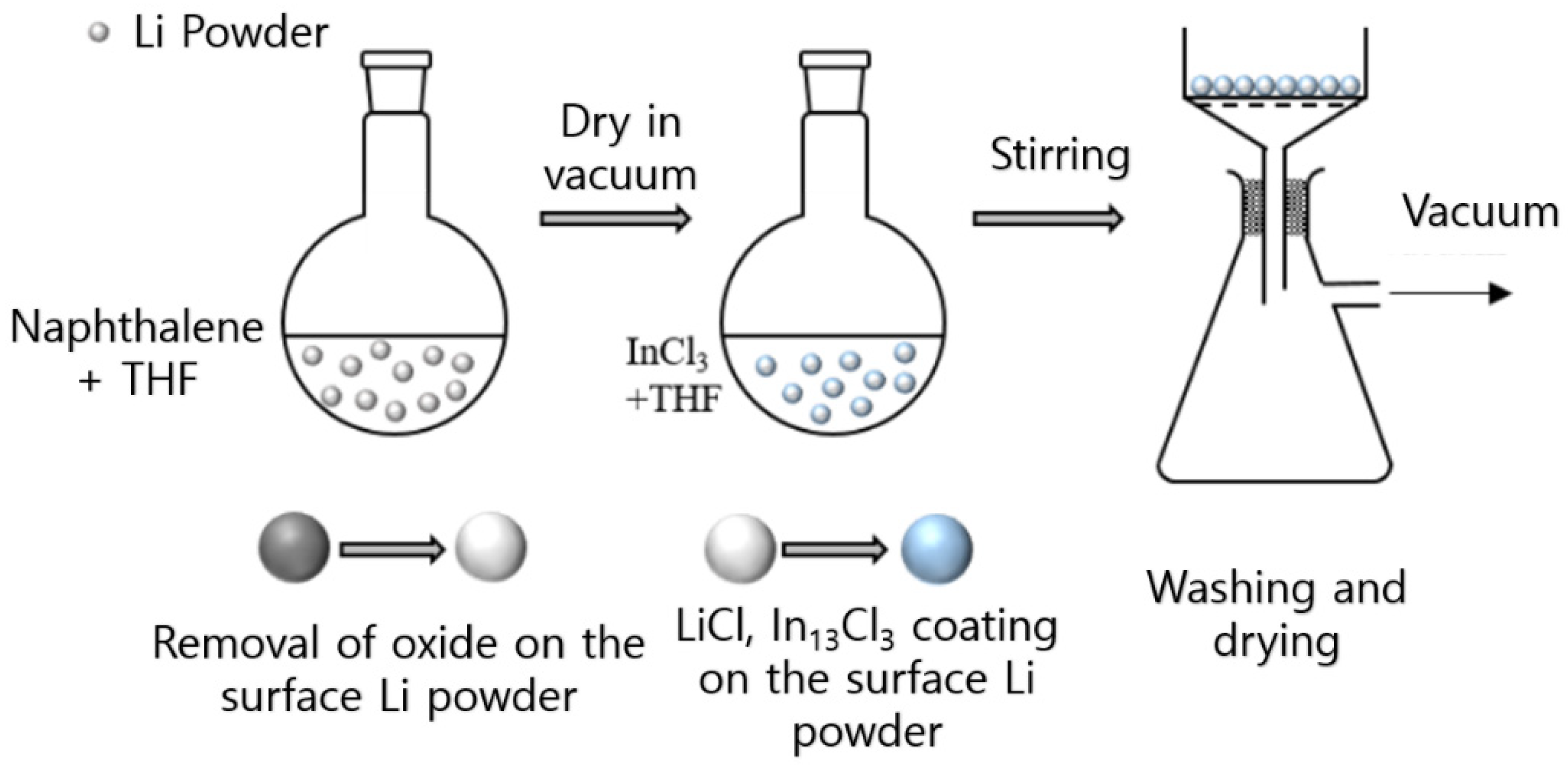
2.1. Synthesis of Coating and Cell Fabrication

Spherical Li powder particles were made using a droplet emulsion technique [42]. The Li powder particles were then chemically polished by etching with a naphthalene solution in tetrahydrofuran (THF) for 1 h, which removed the surface Li oxide layer [43]. The polished Li powder was washed with THF and vacuum dried at 60 °C for 3 h. A LiCl/Li13In3 composite coating was applied to the Li powder by stirring the polished powder in a THF solution of InCl3 for 1 min. The coated lithium powder underwent a total of 5 washing cycles to remove residual InCl3. Each washing cycle involved vacuum filtration using 1 mL of THF with an approximate contact time of 10 s, followed by vacuum drying for 60 °C overnight. The product was a light brown powder. A schematic illustration of the process is presented in Figure 1. The bare and coated Li powders were labeled non-coated Li powder (IC0) and 1 min coated Li powder (IC1), respectively.
The LCE was prepared using the coated Li powder (particle size: approximately 20 μm) mixed with an equal volume of copper powder (Sigma-Aldrich, St. Louis, MO, USA, particle size approximately 10–25 μm, 98% purity). The Li-Cu mixture powder and polyvinylidene fluoride (PVDF, Alfa Aesar, Heysham, MA, USA, 99% purity) were suspended in dimethyl sulfoxide (DMSO, Sigma-Aldrich, Tewksbury, MA, USA, 99% purity) at a 10:1 ratio (by weight) to make a Li-Cu slurry. The slurry was uniformly deposited onto the copper foil and dried at 70 °C for 12 h in a vacuum. The reference electrode was prepared in the same manner as the LCE but instead using bare Li powder. To fabricate the cathode, a slurry was created using Li trivanadate (LiV3O8) as the active material, conductive carbon (Ketjenblack, EC600-JD, AkzoNobel Corp., Amsterdam, The Netherlands) as the conductive agent, and carboxymethylcellulose binder (CMC, Sigma-Aldrich, St. Louis, MO, USA) at a weight ratio of 80:15:5, respectively. The slurry was then applied uniformly onto an aluminum foil, resulting in a thickness of 50 μm, and dried for 12 h at 80 °C. The cathode had an approximate mass of 6.5 mg cm−2 of LiV3O8. All the experiments and fabrication steps were conducted in a glovebox with an argon atmosphere in a dry room.

2.2. Characterization of Coating Materials and Electrodes

The morphology and structure of the bare Li powder and coated Li powder were determined via scanning electron microscopy (SEM, SU-70, Hitachi Co., Tokyo, Japan), energy dispersive X-ray spectroscopy (EDS, SU-70, Hitachi Co., Tokyo, Japan) and X-ray diffraction (XRD) analysis (Rigaku Model D with Cu Kα, Rigaku Co., Tokyo, Japan). After placing the Li powder on the XRD sample holder, it was sealed with polyimide tape to prevent exposure to air. The coating layer was analyzed using X-ray photoelectron spectroscopy (XPS, X-Tool, Ulvac Inc., Chigasaki, Japan) and depth profiles. Sample preparation involved the use of carbon tape for sampling.
An LCE electrolyte was prepared by mixing 1 M LiPF6 in a 1:1 volume ratio of ethylene carbonate and dimethyl carbonate (DEC), along with 3% fluoroethylene carbonate. A polypropylene separator (Celgard 2300, Charlotte, NC, USA) was used to assemble a CR2032 coin cell in a dry room. The cell was then tested using a WBCS 3000 instrument (WonATech Inc., Cheonan-si, Republic of Korea) at 0.2 and 2 C rates in the 2.4–4.0 V range, with all tests performed at 25 °C. Electrochemical impedance spectroscopy (EIS) was carried out using a Solartron SI1280B instrument (TekNet Electronics, Chandler, AZ, USA) over a frequency range of 100 kHz–10 MHz.

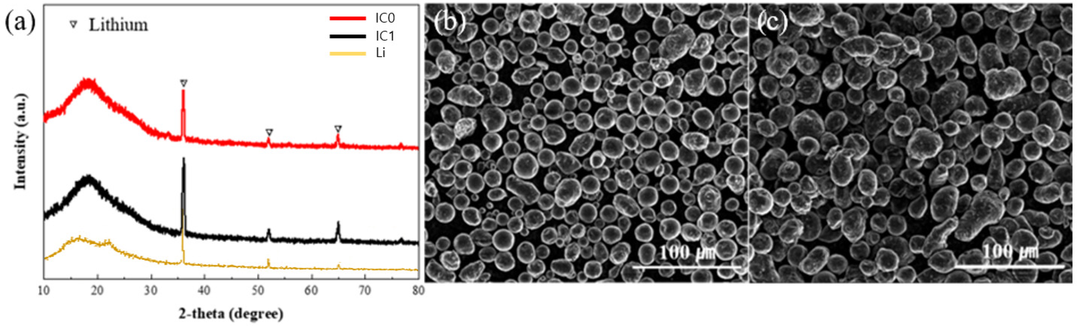
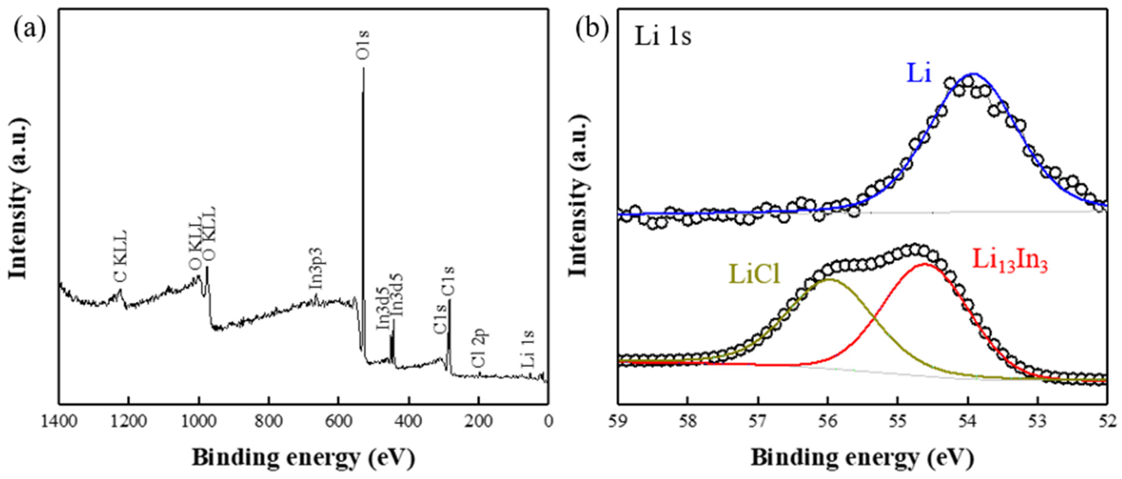
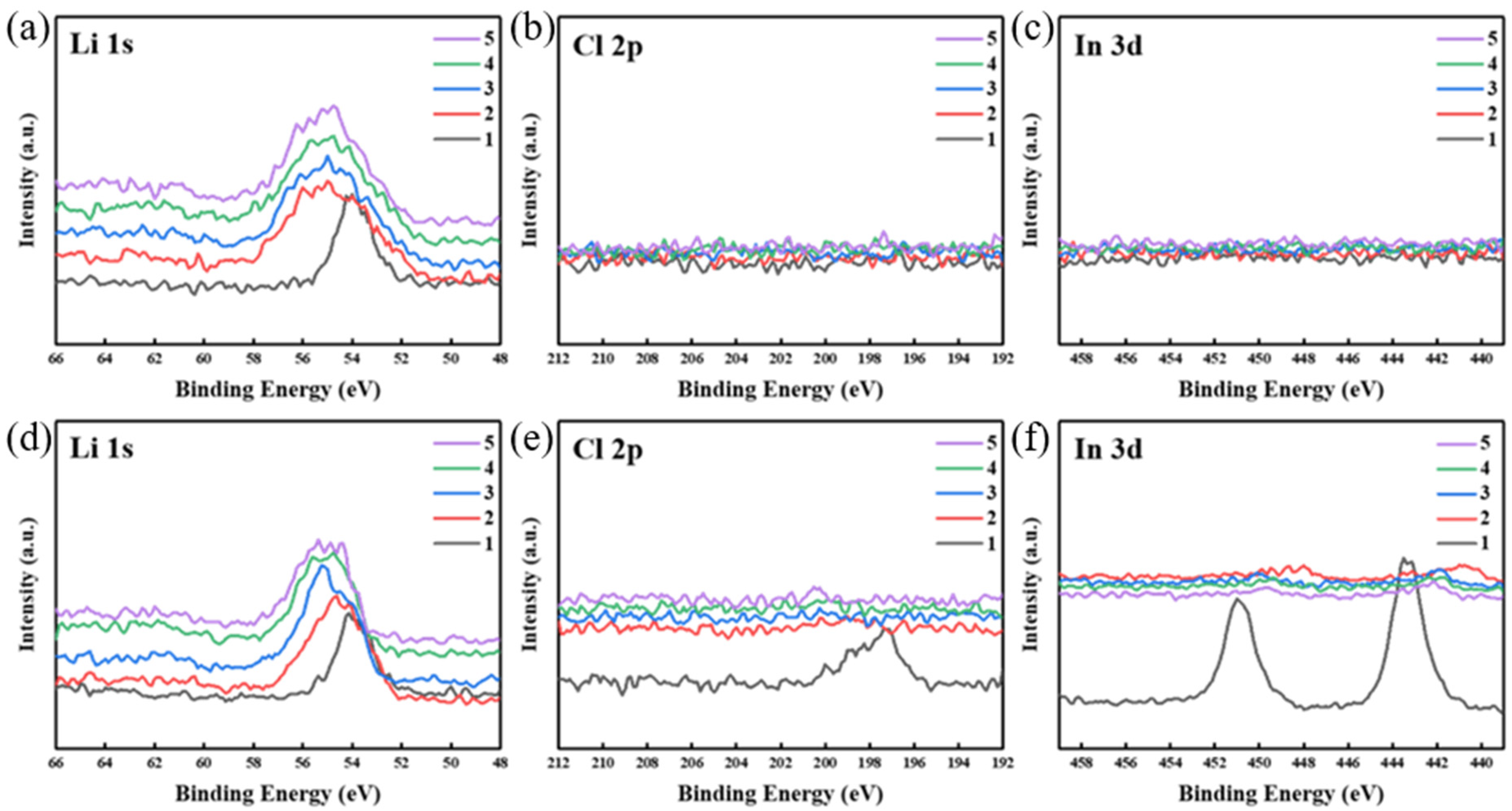
3. Results and Discussion

Figure 1 presents a schematic illustration of the coating process. The color of the Li powder surface became lighter when chemically polished with naphthalene owing to the removal of oxides from the surface. The color of the Li powder changed from light gray to dark brown through the InCl3 treatment process, as shown in Figure 1. The color change is consistent with the report of the Nazar group [34] and can be observed with the naked eye, as shown in Figure S1.
Figure 2a shows the XRD patterns of the Li powder before and after coating. It can be seen that the crystallinity of the Li powder is retained after coating. The XRD patterns of Li are evident for both IC0 and IC1 at 36°, 51.9°, and 64.9°. The amorphous peak below 30° is due to the polyimide tape used to prevent exposure to air [46]. In Figure S2, the EDS mapping image of IC1 and the peaks of In and Cl can be seen. The atomic percentages of In and Cl were 1.25% and 1.44%, respectively. In addition, as shown in Figure S3, we confirmed the presence of In and Cl elements on the surface of a single particle through EDS mapping. The XRD spectrum did not change significantly after coating, likely because the amount of coated material forms only a small part of the electrode (approximately 1%). Figure 2b,c show that the morphology of the Li powder was maintained after coating for 1 min., indicating that the coating layer was very thin compared to the particle size. However, the Li powder coated for 5 and 10 min (IC5 and IC10, respectively, Figure S6) did not maintain its morphology, and the surface of the Li powder became rough. Figure S6 shows that Li13In3 was detected in the XRD profiles (JCPDS card file: 00-033-0615) of IC5 and IC10. It can be seen that IC1 was coated with a thin layer, whereas IC5 and IC10 were coated with thicker layers. Figure S4 shows XRD results analyzed at a higher resolution (1°/min) without covering the syringe tape. In the analysis, LiCl peaks were observed at 26° and 70°, and as the analysis time increased, Li oxidized and formed Li peroxide, which was detected at 41° and 47°.
XPS analysis was performed to determine the composition of the coating layer on the surface of the Li powder. A survey scan of IC1 is shown in Figure 3a. It displays the spectra of In and Cl, which are evidence that the Li surface is coated with these elements. Figure 3b shows the Li 1s peak of IC0 (top) and IC1 (bottom). The spectrum of IC0 exhibits a single peak at 53.8 eV, assigned to Li, whereas the spectrum of IC1 exhibits two overlapping peaks at 56.0 eV and 54.6 eV, attributable to LiCl and Li13In3, respectively [34]. Through XPS analysis, the coating material on the Li powder surface was identified as a composite of LiCl and Li13In3. It has been reported that the Li13In3 layer exhibits very good Li diffusion, and LiCl acts as an electrical insulator that prevents Li deposition on the surface of the coating layer [34]. It was expected that this LiCl/Li13In3 composite coating layer would suppress dendrite growth and volume expansion.
To measure the thickness of the LiCl/Li13In3 composite coating layer, an XPS depth profile analysis was conducted. The test was performed at 30 s intervals with an etching speed of approximately 0.66 nm/s (~20 nm per 30 s cycle) for up to five cycles in a vacuum. Figure 4 shows the depth profiles of IC0 and IC1. The Li 1s spectrum (66–48 eV) of IC0 is shown in Figure 4a, and the spectrum of Li appears in all the cycles (1–5 cycles). In the first cycle of Li, a slight peak shift was observed due to the presence of a fine residual lithium oxide layer on the surface. Figure 4b,c show the Cl 2p and In 3d spectral regions (212–192 and 459–339 eV, respectively) of IC0. As expected, no peaks were observed. Figure 4d shows the Li 1s spectrum of IC1. The Li peak was observed for all cycles. The Cl 2p and In 3d spectra of IC1 are shown in Figure 4e,f, where peaks of LiCl and Li13In3 were observed in the first cycle but not in the second cycle or afterward. This shows that the thickness of the LiCl/Li13In3 composite layer is at most 20 nm. The thickness of the coating layer of IC5 and IC10 was shown to be greater than 100 nm (Figure S7).
Figure 5a presents the result of the symmetric cell test using the prepared electrode (LCE); 40% of the Li capacity (approximately 1544 mAh g−1) was used, and the test was performed at a 2 C rate after 1 cycle at a 0.1 C rate. The initial overpotential of IC1 is approximately 0.14 V, which is significantly higher than the initial overpotential of IC0 (approximately 0.017 V). However, the overpotential of IC1 exhibited much better stability during charge/discharge cycling: the overpotential of IC0 rises to 0.23 V in 21 cycles and to 2.17 V in 23 cycles. Figure S9 shows an extended Y axis of Figure 5a, showing the dramatic increase in IC0′s overpotential compared to IC1. The good stability of IC1 is likely because of the dendrite suppression effect of the LiCl/In13In3 composite coating layer. In Figure S10, the traces for IC5 and IC10 initially show an overpotential of 0.1 V, which rises rapidly after 25 and 20 cycles, respectively. All the coated Li powder electrodes showed a more stable overpotential compared to IC0, and among them, IC1 performed the best. Through the symmetric test, it was shown that the LiCl/Li13In3 composite coating layer affects the electrochemical stability of the electrode, and the most effective thickness of the coating layer (IC1) is at most 20 nm. Figure 5b shows the overpotential of IC0 and IC1 according to Li usage. After testing for five cycles at a 0.2 C rate using 10, 20, 30, 40, and 50% Li, the test was continued with 10% Li usage at a 0.2 C rate. At 10% Li usage of IC1, the initial overpotential was approximately 0.024 V, which was approximately 0.005 V higher than that of IC0 (approximately 0.019 V). Next, the overpotential remains steady up to 40% Li usage, but at 50% usage, it rises rapidly. After returning to 10% Li usage, both IC0 and IC1 showed a stable overpotential of approximately 0.02 V. This remained stable for IC1 until 25 cycles, while IC0 showed a rapid overpotential increase after 18 cycles. The overpotential according to Li usage also confirmed that the LiCl/Li13In3 composite coating layer contributed to the electrochemical stability. Figure 5c,d present the results of a full cell test using the LiV3O8 (LVO) cathode at 0.2 and 2 C rates, respectively. At 0.2 C, the initial specific capacities of IC1 and IC0 were 249.3 and 259.3 mAh g−1, respectively. After 50 cycles, the specific capacities were 199.1 and 105.6 mAh g−1, respectively. This means that the capacity retention rates of IC1 and IC0 after 50 cycles were approximately 80.0% and 40.6%, respectively. In addition, at the 2 C rate, the initial specific capacities of IC1 and IC0 were 168.2 and 188.3 mAh g−1, respectively. After 50 cycles, the specific capacities were 162.0 and 64.6 mAh g−1, and the capacity retention rates were approximately 96.3% and 34.3%, respectively. LVO is a non-lithiated cathode material and should be used as the cathode in Li metal secondary battery systems [47]. Full cell tests have been compared up to 50 cycles. The results show that the improved electrochemical properties of IC1 are retained in a fully working cell than IC0. The reason for this is expected to be that the LiCl/Li13In3 composite coating layer effectively suppressed dendrite growth.
The cross-sectional SEM images of Figure 6a,b show the thickness of IC1, approximately 40 µm, as well as homogeneously mixed copper powder and Li powder. In Figure 6d, the relatively dark spherical particles are Li (particle size: approximately 20 μm), and the lighter particles with a mixture of spherical and dimorphic forms (10–25 μm particle size) are copper. From the EDS mapping image in Figure S8, it is possible to confirm the well-dispersed state of the copper and Li powders macroscopically. In addition, it was confirmed that the spherical shape of the Li particles was well maintained, and the contact with the copper powder was good. Figure 6b,e show SEM images of the cross-section and top view of an IC1 anode after 50 charge/discharge cycles at a 0.2 C rate. These images confirm that the spherical shape of the Li powder was maintained, and dendrite formation was minimal. Figure 6c,f show SEM images of the cross-section and top view of an IC0 anode after 50 cycles at 0.2 C rate. The cross-section (Figure 6c) shows that the spherical shape of the Li powder was partially maintained, but substantial dendrite growth was observed. The top view SEM image (Figure 6f) shows that dendrite growth occurred over the whole electrode surface. Figure S11 is an enlarged image of the red box in Figure 6f, which more clearly shows the dendrite growth. In addition, in Figure 6b, it can be seen that the thickness of the IC1 electrode was practically unchanged at approximately 40 µm after 50 cycles. In contrast, the thickness of the IC0 electrode was approximately 50 μm after 50 cycles; the volume increased owing to dendrite growth (Figure 6c). This suppression of volume change is an additional advantage offered by the LCE electrode architecture that may produce a synergetic increase in electrochemical stability.
For a more comprehensive understanding of the enhanced electrochemical behavior of the LiCl/Li13In3 composite coating layer, EIS analysis of IC1 and IC0 was conducted. Figure 7a shows the impedance results of IC1 and IC0 before cycling. The charge transfer resistance (Rct) values calculated from these data are approximately 450 Ω and 350 Ω for the two anode types, respectively. This means that the impedance value increased by approximately 100 Ω after the LiCl/Li13In3 composite coating. This may explain why the initial capacity of IC0 was higher than that of IC1 in the full cell test. This is also likely the reason that the initial overpotential of IC0 is higher than that of IC1 in the symmetric test. After 50 cycles of the full cell test under a 0.2 C rate condition (Figure 7b), the impedance of IC1 decreased to 98 Ω, whereas the impedance of IC0 remained unchanged at 350 Ω. The impedance of IC1 is likely lower than that of IC0 after cycling because the LiCl/Li13In3 composite coating suppressed dendrite growth.

4. Conclusions

In this study, Li dendrite growth and volume expansion of a Li anode were effectively suppressed with a hybrid Li host design incorporating an SEI film. A Li–Cu composite electrode (LCE) was used to prevent the localization of current, and a LiCl/Li13In3 composite artificial SEI layer was formed on the Li powder surface via a facile mixing method. The LCE showed improved electrochemical properties in the symmetric cell and full cell tests. In particular, even when 40% Li was used (1544 mAh g−1), it showed safe electrochemical behavior for 50 cycles in the symmetric test. In addition, in a full cell test using LiV3O8 as a cathode at a 2 C rate, the capacity retention rate was approximately 96% after 50 cycles. This is because the growth of dendrites was suppressed owing to the synergy of the LiCl/Li13In3 composite artificial SEI and the designed Li host with LCE. Furthermore, the LCE prevented volume changes at the Li anode during repeated charge/discharge cycles. The results obtained suggest that the hybrid method combining a Li host design and an SEI film are effective ways to inhibit Li dendrite growth in LMSBs.

Supplementary Materials

The following supporting information can be downloaded at: https://www.mdpi.com/article/10.3390/batteries9060299/s1, Figure S1. Color change of Li powder (from left to right: stock Li powder, after polishing with naphthalene, after LiCl/Li13In3 composite coating). Figure S2. SEM and EDX images for Cl and In (above) and the ratio of atomic and weight percentages (below) of O, Cl, and In of IC1 (below). Figure S3. SEM and EDX images of Cl and In distribution in a single particle of IC1. Figure S4. High resolution (1˚/min) XRD data of IC1 without syringe tape. Figure S5. SEM images of IC5 (left) and IC10 (right). Figure S6. XRD patterns of the IC0, IC1, IC5 and IC10. Figure S7. Depth profile of high-resolution XPS spectra profiles of (a) IC5 and (b) IC10 (In 3D). Figure S8. SEM image of LCE made with IC1. Figure S9. Symmetric test of IC0 and IC1 at 0.1 C rate (Y-axis zoomed). Figure S10. Symmetric test of IC5 and IC10 at 0.1 C rate. Figure S11. SEM image of the IC0 electrode after 50 cycles.

Author Contributions

Conceptualization, S.C. and W.Y.Y.; formal analysis, B.H.K.; investigation, S.C.; resources, W.Y.Y.; data curation, B.H.K. and S.C; writing—original draft preparation, S.C.; writing—review and editing, S.C.; visualization, S.C.; funding acquisition, W.Y.Y. All authors have read and agreed to the published version of the manuscript.

Funding

This work was supported by grants from the National Research Foundation of Korea (NRF), the Korean government (MSIT) (2020R1A2C1012838), and supported by the Industry-Academia Collabo program of Ministry of SMEs and Startups(MSS, Korea). [2021(S3093231)]. SEM and EDX examinations were performed at the Korea Basic Science Institute, Seoul Center.

Conflicts of Interest

The authors declare no conflict of interest.

References

  1. Choi, J.W.; Aurbach, D. Promise and reality of post-lithium-ion batteries with high energy densities. Nat. Rev. Mater. 2016, 1, 16013. [Google Scholar] [CrossRef]
  2. Tikekar, M.D.; Choudhury, S.; Tu, Z.Y.; Archer, L.A. Design principles for electrolytes and interfaces for stable lithium-metal batteries. Nat. Energy 2016, 1, 16114. [Google Scholar] [CrossRef]
  3. Cheng, X.B.; Zhang, R.; Zhao, C.Z.; Zhang, Q.Q. Toward Safe Lithium Metal Anode in Rechargeable Batteries: A Review. Chem. Rev. 2017, 1, 10403–10473. [Google Scholar] [CrossRef] [PubMed]
  4. Bruce, P.G.; Freunberger, S.A.; Hardwick, L.J.; Tarascon, J.-M. Li–O2 and Li–S batteries with high energy storage. Nat. Mater. 2012, 1, 19–29. [Google Scholar] [CrossRef]
  5. Xu, W.; Wang, J.; Ding, F.; Chen, X.; Nasybulin, E.; Zhang, Y.; Zhang, J. Lithium metal anodes for rechargeable batteries. Energy Environ. Sci. 2014, 1, 513–537. [Google Scholar] [CrossRef]
  6. Scrosati, B.; Garche, J. Lithium batteries: Status, prospects and future. J. Power Sources 2010, 1, 2419–2430. [Google Scholar] [CrossRef]
  7. Luo, W.; Zhou, L.; Fu, K.; Yang, Z.; Wan, J.; Manno, M.; Yao, Y.; Zhu, H.; Yang, B.; Hu, L. A Thermally Conductive Separator for Stable Li Metal Anodes. Nano Lett. 2015, 1, 6149–6154. [Google Scholar] [CrossRef]
  8. You, J.; Zhang, S.; Deng, L.; Li, M.; Zheng, X.; Li, J.; Zhou, Y.; Huang, L.; Sun, S. Suppressing Li dendrite by a protective biopolymeric film from tamarind seed polysaccharide for high-performance Li metal anode. Electrochim. Acta 2019, 1, 636–644. [Google Scholar] [CrossRef]
  9. Wang, G.; Xiong, X.; Xie, D.; Fu, X.; Ma, X.; Li, Y.; Liu, Y.; Lin, Z.; Yang, C.; Liu, M. Suppressing dendrite growth by a functional electrolyte additive for robust Li metal anodes. Energy Storage Mater. 2019, 1, 701–706. [Google Scholar] [CrossRef]
  10. Becking, J.; Grobmeyer, A.; Kolek, M.; Rodehorst, U.; Schulze, S.; Winter, M.; Bieker, P.; Stan, M.C. Lithium-Metal Foil Surface Modification: An Effective Method to Improve the Cycling Performance of Lithium-Metal Batteries. Adv. Mater. Interfaces 2017, 1, 7100166. [Google Scholar] [CrossRef]
  11. Chen, L.; Li, W.; Fan, L.Z.; Nan, C.W.; Zhang, Q. Intercalated Electrolyte with High Transference Number for Dendrite-Free Solid-State Lithium Batteries. Adv. Funct. Mater. 2019, 1, 1901047. [Google Scholar] [CrossRef]
  12. Yu, S.H.; Huang, X.; Brock, J.D.; Abruna, H.D. Regulating Key Variables and Visualizing Lithium Dendrite Growth: An Operando X-ray Study. J. Am. Chem. Soc. 2019, 1, 8441–8449. [Google Scholar] [CrossRef]
  13. Lopez, J.; Pei, A.; Oh, J.Y.; Wang, G.N.; Cui, Y.; Bao, Z. Effects of Polymer Coatings on Electrodeposited Lithium Metal. J. Am. Chem. Soc. 2018, 1, 11735–11744. [Google Scholar] [CrossRef] [PubMed]
  14. Liu, H.; Cheng, X.B.; Xu, R.; Zhang, X.Q.; Yan, C.; Huang, J.Q.; Zhang, Q. Plating/Stripping Behavior of Actual Lithium Metal Anode. Adv. Energy Mater. 2019, 1, 1902254. [Google Scholar] [CrossRef]
  15. Zhao, J.; Liao, L.; Shi, F.; Lei, T.; Chen, G.; Pei, A.; Sun, J.; Yan, K.; Zhou, G.; Xie, J.; et al. Surface Fluorination of Reactive Battery Anode Materials for Enhanced Stability. J. Am. Chem. Soc. 2017, 1, 11550–11558. [Google Scholar] [CrossRef]
  16. Li, W.; Yao, H.; Yan, K.; Zheng, G.; Liang, Z.; Chiang, Y.M.; Cui, Y. The synergetic effect of lithium polysulfide and lithium nitrate to prevent lithium dendrite growth. Nat. Commun. 2015, 1, 7436. [Google Scholar] [CrossRef]
  17. Lei, Q.; Zhang, Q.; Wu, X.; Wei, X.; Zhang, J.; Wang, K.; Chen, J. Towards ultra-stable lithium metal batteries: Interfacial ionic flux regulated through LiAl LDH-modified polypropylene separator. Chem. Eng. 2020, 395, 125187. [Google Scholar] [CrossRef]
  18. Ma, L.; Kim, M.; Archer, L.A. Stable Artificial Solid Electrolyte Interphases for Lithium Batteries. Chem. Mater. 2017, 1, 4181–4189. [Google Scholar] [CrossRef]
  19. Lu, Y.; Tu, Z.; Archer, L.A. Stable lithium electrodeposition in liquid and nanoporous solid electrolytes. Nat. Mater. 2014, 1, 961–969. [Google Scholar] [CrossRef] [PubMed]
  20. Ding, F.; Wu, W.; Graff, G.L.; Zhang, J.; Sushko, M.L.; Chen, X.; Shao, Y.; Engelhard, M.H.; Nie, Z.; Xiao, J.; et al. Dendrite-Free Lithium Deposition via Self-Healing Electrostatic Shield Mechanism. J. Am. Chem. Soc. 2013, 1, 4450–4456. [Google Scholar] [CrossRef]
  21. Zheng, G.; Lee, S.; Liang, Z.; Lee, H.; Yan, K.; Yao, H.; Wang, H.; Li, W.; Chu, S.; Cui, Y. Interconnected hollow carbon nanospheres for stable lithium metal anodes. Nat. Nanotechnol. 2014, 1, 618–623. [Google Scholar] [CrossRef] [PubMed]
  22. Yan, K.; Lee, H.; Gao, T.; Yao, H.; Wang, H.; Lu, Z.; Zhou, Y.; Liang, Z.; Liu, Z.; Chu, S.; et al. Ultrathin Two-Dimensional Atomic Crystals as Stable Interfacial Layer for Improvement of Lithium Metal Anode. Nano. Lett. 2014, 1, 6016–6022. [Google Scholar] [CrossRef]
  23. Lin, D.; Liu, Y.; Chen, W.; Zhou, G.; Liu, K.; Dunn, B.; Cui, Y. Conformal Lithium Fluoride Protection Layer on Three-Dimensional Lithium by Nonhazardous Gaseous Reagent Freon. Nano. Lett. 2017, 1, 3731–3737. [Google Scholar] [CrossRef]
  24. Li, Y.; Sun, Y.; Pei, A.; Chen, K.; Vailionis, A.; Li, Y.; Zheng, G.; Sun, J.; Cui, Y. Robust Pinhole-free Li3N Solid Electrolyte Grown from Molten Lithium. ACS. Cent. Sci. 2018, 1, 97–104. [Google Scholar] [CrossRef] [PubMed]
  25. Li, N.; Yin, Y.; Yang, C.; Guo, Y. An Artificial Solid Electrolyte Interphase Layer for Stable Lithium Metal Anodes. Adv. Mater. 2016, 1, 1853–1858. [Google Scholar] [CrossRef] [PubMed]
  26. Kozen, A.C.; Lin, C.F.; Pearse, A.J.; Schroeder, M.A.; Han, X.; Hu, L.; Lee, S.B.; Rubloff, G.W.; Noked, M. Next-Generation Lithium Metal Anode Engineering via Atomic Layer Deposition. ACS. Nano. 2015, 1, 5884–5892. [Google Scholar] [CrossRef]
  27. Jia, W.; Wang, Q.; Yang, J.; Fan, C.; Wang, L.; Li, J. Pretreatment of Lithium Surface by Using Iodic Acid (HIO3) To Improve Its Anode Performance in Lithium Batteries. ACS Appl. Mater. Interfaces 2017, 1, 7068–7074. [Google Scholar] [CrossRef]
  28. Song, J.; Lee, H.; Choo, M.J.; Park, J.K.; Kim, H.T. Ionomer-Liquid Electrolyte Hybrid Ionic Conductor for High Cycling Stability of Lithium Metal Electrodes. Sci. Rep. 2015, 1, 14458. [Google Scholar] [CrossRef]
  29. Li, N.W.; Shi, Y.; Yin, Y.X.; Zeng, X.X.; Li, J.Y.; Li, C.J.; Wan, L.J.; Wen, R.; Guo, Y.G. Inside Cover: A Flexible Solid Electrolyte Interphase Layer for Long-Life Lithium Metal Anodes (Angew. Chem. Int. Ed. 6/2018). Angew. Chem. Int. Ed. 2018, 1, 1422. [Google Scholar] [CrossRef]
  30. Belov, D.G.; Yarmolenko, O.V.; Peng, A.; Efimov, O.N. Lithium surface protection by polyacetylene in situ polymerization. Synth. Met. 2006, 1, 745–751. [Google Scholar] [CrossRef]
  31. Liu, Y.; Lin, D.; Yuen, P.Y.; Liu, K.; Xie, J.; Dauskardt, R.H.; Cui, Y. An Artificial Solid Electrolyte Interphase with High Li-Ion Conductivity, Mechanical Strength, and Flexibility for Stable Lithium Metal Anodes. Adv. Mater. 2017, 1, 1605531. [Google Scholar] [CrossRef] [PubMed]
  32. Zhu, B.; Jin, Y.; Hu, X.; Zheng, Q.; Zhang, S.; Wang, Q.; Zhu, J. Poly(dimethylsiloxane) Thin Film as a Stable Interfacial Layer for High-Performance Lithium-Metal Battery Anodes. Adv. Mater. 2017, 1, 1603755. [Google Scholar] [CrossRef] [PubMed]
  33. Zheng, G.; Wang, C.; Pei, A.; Lopez, J.; Shi, F.; Chen, Z.; Sendek, A.D.; Lee, H.W.; Lu, Z.; Schneider, H.; et al. High-Performance Lithium Metal Negative Electrode with a Soft and Flowable Polymer Coating. ACS Energy Lett. 2016, 1, 1247–1255. [Google Scholar] [CrossRef]
  34. Wang, H.; Liu, Y.; Li, Y.; Cui, Y. Lithium Metal Anode Materials Design: Interphase and Host. Electrochem. Energy Rev. 2019, 1, 509–517. [Google Scholar] [CrossRef]
  35. Liang, X.; Pang, Q.; Kochetkov, I.R.; Sempere, M.S.; Huang, H.; Sun, X.; Nazar, L.F. A facile surface chemistry route to a stabilized lithium metal anode. Nat. Energy 2017, 1, 17119. [Google Scholar] [CrossRef]
  36. Lin, D.; Liu, Y.; Liang, Z.; Lee, H.W.; Sun, J.; Wang, H.; Yan, K.; Xie, J.; Cui, Y. Layered reduced graphene oxide with nanoscale interlayer gaps as a stable host for lithium metal anodes. Nat. Nanotechnol. 2016, 11, 626–632. [Google Scholar] [CrossRef]
  37. Yang, C.P.; Yin, Y.X.; Zhang, S.F.; Li, N.W.; Guo, Y.G. Accommodating lithium into 3D current collectors with a submicron skeleton towards long-life lithium metal anodes. Nat. Commun. 2015, 1, 8058. [Google Scholar] [CrossRef]
  38. Zhang, R.; Cheng, X.B.; Zhao, C.Z.; Peng, H.J.; Shi, J.L.; Huang, J.Q.; Wang, J.; Wei, F.; Zhang, Q. Conductive Nanostructured Scaffolds Render Low Local Current Density to Inhibit Lithium Dendrite Growth. Adv. Mater. 2016, 1, 2155–2162. [Google Scholar] [CrossRef]
  39. Zhang, R.; Cheng, X.; Shen, X.; Zhang, X.; Chen, X.; Cheng, X.; Yan, C.; Zhao, C.; Zhang, Q. Porous Cryo-Dried MXene for Efficient Capacitive Deionization. Joule 2018, 1, 764–777. [Google Scholar] [CrossRef]
  40. Sun, Y.; Zheng, G.; Seh, Z.; Liu, N.; Wang, S.; Sun, J.; Lee, H.; Cui, Y. Graphite-Encapsulated Li-Metal Hybrid Anodes for High-Capacity Li Batteries. Chem 2016, 1, 287–297. [Google Scholar] [CrossRef]
  41. Zhang, Y.; Liu, B.; Hitz, E.; Luo, W.; Yao, Y.; Li, Y.; Dai, J.; Chen, C.; Wang, Y.; Yang, C.; et al. A carbon-based 3D current collector with surface protection for Li metal anode. Nano Res. 2014, 1, 11503–11618. [Google Scholar] [CrossRef]
  42. Tang, W.; Yin, X.; Chen, Z.; Fu, W.; Loh, K.P.; Zheng, G.W. Chemically polished lithium metal anode for high energy lithium metal batteries. Energy Storage Mater. 2018, 1, 289–296. [Google Scholar] [CrossRef]
  43. Hwang, S.W.; Yom, J.H.; Cho, S.M.; Yoon, W.Y. Electrochemical Behavior of Li–Cu Composite Powder Electrodes in Lithium Metal Secondary Batteries. ACS Appl. Mater. Interfaces 2017, 1, 22530–22538. [Google Scholar] [CrossRef] [PubMed]
  44. Kim, J.S.; hoon Baek, S.; Yoon, W.Y. Electrochemical Behavior of Compacted Lithium Powder Electrode in Li / V2O5 Rechargeable Battery. J. Electrochem. Soc. 2010, 1, A984–A987. [Google Scholar] [CrossRef]
  45. Son, B.; Bae, K.; Lee, K.; Yoon, W. Erratum: Electrochemical Behaviors of Lithium Powder Anode in Lithium-Sulfur Battery [J. Electrochem. Soc., 167, 100549 (2020)]. J. Electrochem. Soc. 2020, 1, 119001. [Google Scholar] [CrossRef]
  46. Jin, D.; Oh, J.; Friesen, A.; Kim, K.; Jo, T.; Lee, Y.M.; Ryou, M.H. Self-Healing Wide and Thin Li Metal Anodes Prepared Using Calendared Li Metal Powder for Improving Cycle Life and Rate Capability. ACS Appl. Mater. Interfaces 2018, 1, 16521–16530. [Google Scholar] [CrossRef] [PubMed]
  47. Ma, G.; Wen, Z.; Wu, M.; Shen, C.; Wang, Q.; Jin, J.; Wu, X. A lithium anode protection guided highly-stable lithium–sulfur battery†. Chem. Commun. 2014, 1, 14209. [Google Scholar] [CrossRef]
Figure 1. Schematic illustration of the process of polishing and coating the surface of powdered Li powder particles.
Batteries 09 00299 g001
Figure 2. (a) XRD patterns of IC0 and IC1. SEM image of (b) IC0 and (c) IC1.
Batteries 09 00299 g002
Figure 3. (a) Nature of XPS analysis survey scan of IC1, and (b) high-resolution Li 1s spectra of IC0 (top) and IC1 (bottom).
Batteries 09 00299 g003
Figure 4. Depth profile of high-resolution XPS spectra of (ac) IC0 and (df) IC1 (Li 1s, Cl 2p, and In 3d, respectively).
Batteries 09 00299 g004
Figure 5. (a) Symmetric test of IC0 and IC1 at 0.1 C rate and (b) overpotential according to Li usage of IC0 and IC1 at 0.2 C rate. Cyclic performance of IC0 and IC1 at (c) 0.2 C rate and (d) 2 C rate.
Batteries 09 00299 g005
Figure 6. SEM images of (a,d) IC1 electrode before cycles, (b,e) IC1 electrode after 50 cycles, and (c,f) IC0 electrode after 50 cycles at full cell test at 0.2 C rate (ac) cross-view and (df) top view, the red box of (f) enlarged view is presented in Figure S11.
Batteries 09 00299 g006
Figure 7. Impedance data of IC0 and IC1 (a) before cycling and (b) after 50 cycles.
Batteries 09 00299 g007
Disclaimer/Publisher’s Note: The statements, opinions and data contained in all publications are solely those of the individual author(s) and contributor(s) and not of MDPI and/or the editor(s). MDPI and/or the editor(s) disclaim responsibility for any injury to people or property resulting from any ideas, methods, instructions or products referred to in the content.

