

In Situ Metal Organic Framework (ZIF-8) and Mechanofusion-Assisted MWCNT Coating of LiFePO4/C Composite Material for Lithium-Ion Batteries
 ,
,  ,
,  and
and
Abstract
:
1. Introduction
2. Experimental Section
2.1. Preparation of ZIF-8
2.2. Preparation of ZIF-8-Modified LFP Composite by a Magnetic Stirrer Method
2.3. Preparation of 2 wt.% ZIF-8@LFP Composite by an Agitator Method
2.4. Preparation of 2 wt.% ZIF-8@LFP/MWCNT Composite by a Dry-Coating Method
2.5. Instrumentation
2.6. Electrode Fabrication and Measurements
3. Results and Discussion
3.1. Material Characterization
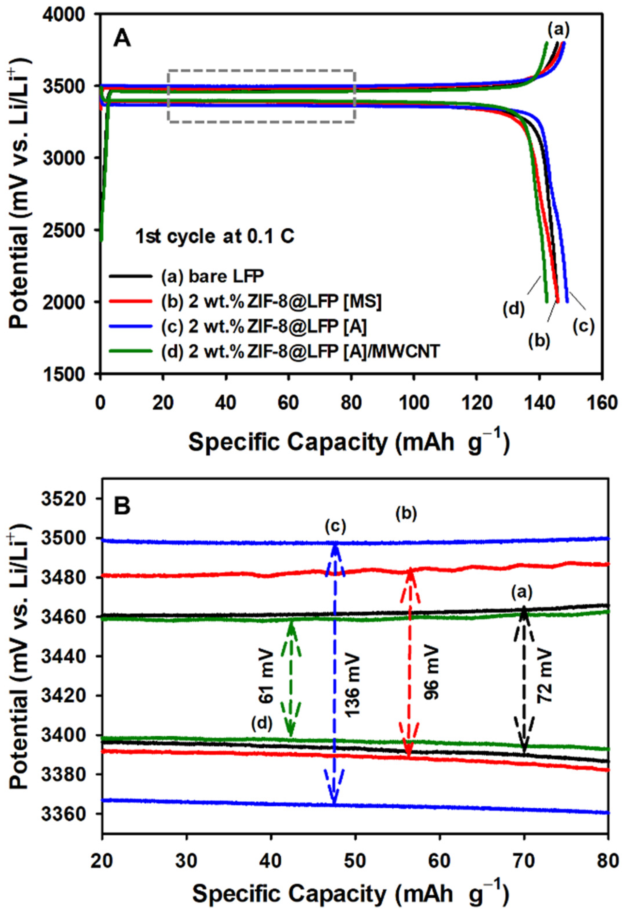
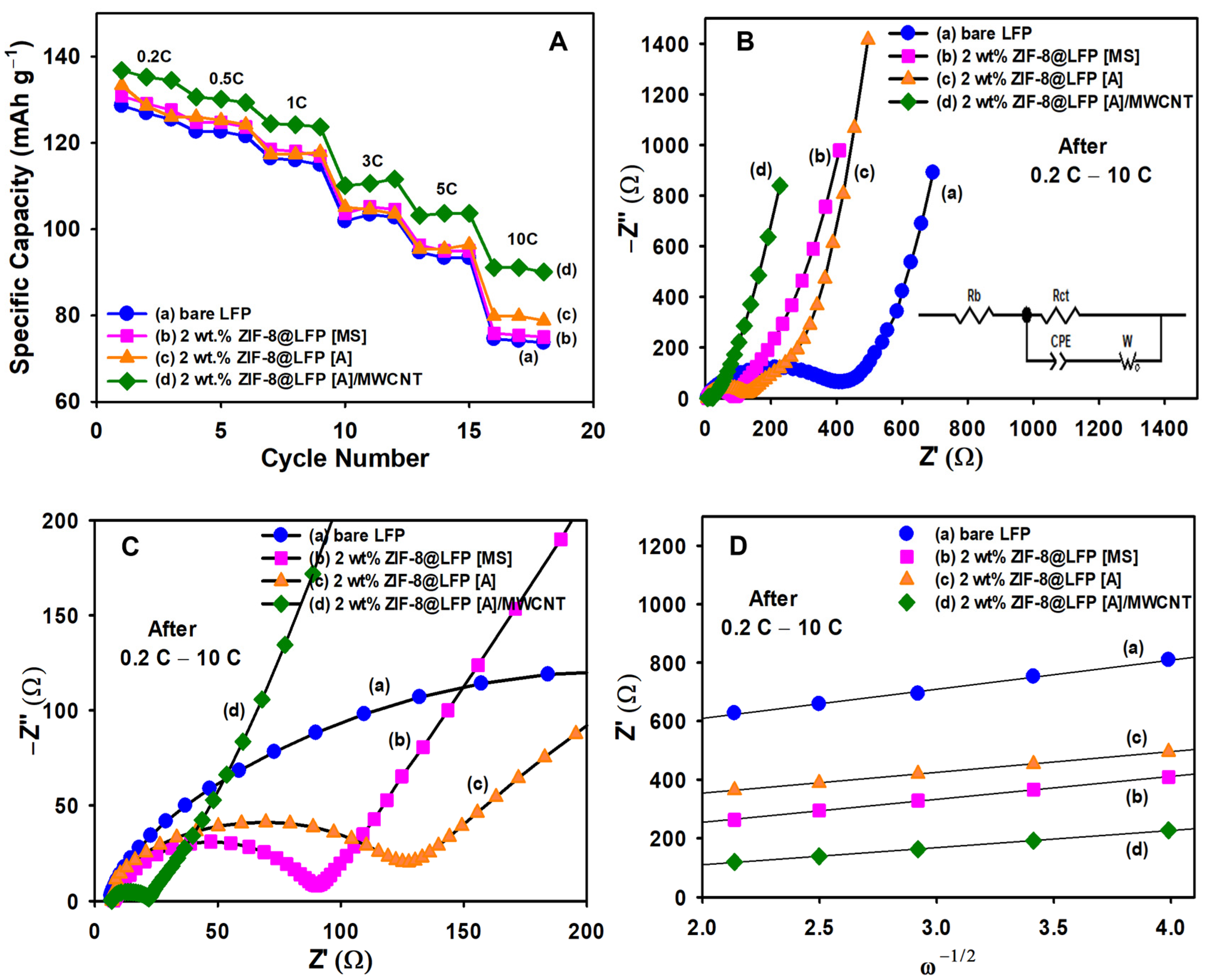
3.2. Electrochemical Performance
4. Conclusions
Supplementary Materials
Author Contributions
Funding
Informed Consent Statement
Data Availability Statement
Acknowledgments
Conflicts of Interest
References
- Manthiram, A. An Outlook on Lithium Ion Battery Technology. ACS Cent. Sci. 2017, 3, 1063–1069. [Google Scholar] [CrossRef] [Green Version]
- Cao, Z.; Zhu, G.; Zhang, R.; Chen, S.; Sang, M.; Jia, J.; Yang, M.; Li, X.; Yang, S. Biological Phytic Acid Guided Formation of Monodisperse Large-Sized Carbon@LiFePO4/Graphene Composite Microspheres for High-Performance Lithium-Ion Battery Cathodes. Chem. Eng. J. 2018, 351, 382–390. [Google Scholar] [CrossRef]
- Wang, X.; Feng, Z.; Hou, X.; Liu, L.; He, M.; He, X.; Huang, J.; Wen, Z. Fluorine Doped Carbon Coating of LiFePO4 as a Cathode Material for Lithium-Ion Batteries. Chem. Eng. J. 2020, 379, 122371. [Google Scholar] [CrossRef]
- Cheng, Y.; Zhou, L.; Cai, X.; Cui, X.; Wu, S.; Pan, W.; Li, W. Effect of High-Energy Ball Milling Mixing Process on Electrical Performance and Synthesis Temperature of LiFePO4/C Cathode Material. Integr. Ferroelectr. 2022, 227, 202–213. [Google Scholar] [CrossRef]
- Huang, Y.; Liu, H.; Gong, L.; Hou, Y.; Li, Q. A Simple Route to Improve Rate Performance of LiFePO4/Reduced Graphene Oxide Composite Cathode by Adding Mg2+ via Mechanical Mixing. J. Power Sources 2017, 347, 29–36. [Google Scholar] [CrossRef]
- Erabhoina, H.; Thelakkat, M. Tuning of Composition and Morphology of LiFePO4 Cathode for Applications in All Solid-State Lithium Metal Batteries. Sci. Rep. 2022, 12, 1–14. [Google Scholar] [CrossRef]
- Zhou, Y.; Lu, J.; Deng, C.; Zhu, H.; Chen, G.Z.; Zhang, S.; Tian, X. Nitrogen-Doped Graphene Guided Formation of Monodisperse Microspheres of LiFePO4 Nanoplates as the Positive Electrode Material of Lithium-Ion Batteries. J. Mater. Chem. A 2016, 4, 12065–12072. [Google Scholar] [CrossRef]
- Wang, C.; Yuan, X.; Tan, H.; Jian, S.; Ma, Z.; Zhao, J.; Wang, X.; Chen, D.; Dong, Y. Three-Dimensional Carbon-Coated LiFePO4 Cathode with Improved Li-Ion Battery Performance. Coatings 2021, 11, 1137. [Google Scholar] [CrossRef]
- Yi, D.; Cui, X.; Li, N.; Zhang, L.; Yang, D. Enhancement of Electrochemical Performance of LiFePO4@C by Ga Coating. ACS Omega 2020, 5, 9752–9758. [Google Scholar] [CrossRef] [PubMed] [Green Version]
- Zhang, J.; Nie, N.; Liu, Y.; Wang, J.; Yu, F.; Gu, J.; Li, W. Boron and Nitrogen Codoped Carbon Layers of LiFePO4 Improve the High-Rate Electrochemical Performance for Lithium Ion Batteries. ACS Appl. Mater. Interfaces 2015, 7, 20134–20143. [Google Scholar] [CrossRef]
- Zhao, Q.F.; Yu, Y.H.; Ouyang, Q.S.; Hu, M.Y.; Wang, C.; Ge, J.H.; Zhang, S.Q.; Jiang, G.H. Surface Modification of LiFePO4 by Coatings for Improving of Lithium-Ion Battery Properties. Int. J. Electrochem. Sci. 2022, 17, 221142. [Google Scholar] [CrossRef]
- Yang, C.C.; Jiang, J.R.; Karuppiah, C.; Jang, J.H.; Wu, Z.H.; Jose, R.; Lue, S.J. LATP Ionic Conductor and In-Situ Graphene Hybrid-Layer Coating on LiFePO4 Cathode Material at Different Temperatures. J. Alloys Compd. 2018, 765, 800–811. [Google Scholar] [CrossRef]
- Nguyen, D.T.; Kim, J.; Lee, Y. A Hybrid Carbon–Li1.3Al0.3Ti1.7(PO4)3 Conductive Coating for High Current Rate LiFePO4 Cathode Material. Chem. Eng. J. 2023, 7, 141750. [Google Scholar] [CrossRef]
- Mandal, S.; Natarajan, S.; Mani, P.; Pankajakshan, A. Post-Synthetic Modification of Metal–Organic Frameworks Toward Applications. Adv. Funct. Mater. 2021, 31, 1–22. [Google Scholar] [CrossRef]
- Wang, Y.; Chen, B.; Zhang, Y.; Fu, L.; Zhu, Y.; Zhang, L.; Wu, Y. ZIF-8@MWCNT-Derived Carbon Composite as Electrode of High Performance for Supercapacitor. Electrochim. Acta 2016, 213, 260–269. [Google Scholar] [CrossRef]
- Jafari, N.; Zeinali, S. Highly Rapid and Sensitive Formaldehyde Detection at Room Temperature Using a ZIF-8/MWCNT Nanocomposite. ACS Omega 2020, 5, 4395–4402. [Google Scholar] [CrossRef] [PubMed] [Green Version]
- Xu, Q.; Jiang, H.; Li, Y.; Liang, D.; Hu, Y.; Li, C. In-Situ Enriching Active Sites on Co-Doped Fe-Co4N@N-C Nanosheet Array as Air Cathode for Flexible Rechargeable Zn-Air Batteries. Appl. Catal. B Environ. 2019, 256, 117893. [Google Scholar] [CrossRef]
- Liu, M.; Xiao, X.; Zhao, S.; Saremi-Yarahmadi, S.; Chen, M.; Zheng, J.; Li, S.; Chen, L. ZIF-67 Derived Co@CNTs Nanoparticles: Remarkably Improved Hydrogen Storage Properties of MgH2 and Synergetic Catalysis Mechanism. Int. J. Hydrogen Energy 2019, 44, 1059–1069. [Google Scholar] [CrossRef]
- Ashtiani, S.; Khoshnamvand, M.; Shaliutina-Kolešová, A.; Bouša, D.; Sofer, Z.; Friess, K. Co0·5Ni0·5FeCrO4 Spinel Nanoparticles Decorated with UiO-66-Based Metal-Organic Frameworks Grafted onto GO and O-SWCNT for Gas Adsorption and Water Purification. Chemosphere 2020, 255, 126966. [Google Scholar] [CrossRef]
- Hsu, L.F.; Venkatesh, K.; Karuppiah, C.; Ramaraj, S.K.; Yang, C.C. Incorporation of ZIF-67 Derived Co-N/C Core-Shell Nanoparticles on Functionalized MWCNT as a Highly Efficient Electrocatalyst for Nonenzymatic H2O2 Sensor. Colloids Surfaces A Physicochem. Eng. Asp. 2022, 654, 130133. [Google Scholar] [CrossRef]
- Hira, S.A.; Park, K.H. Nitrogen-Doped Zeolitic Imidazolate Framework and Particle-Reduced Graphene Oxide Composites as Electrochemical Sensors and Battery-Type Supercapacitors. ACS Appl. Nano Mater. 2021, 4, 7870–7878. [Google Scholar] [CrossRef]
- Tan, P.C.; Ooi, B.S.; Ahmad, A.L.; Low, S.C. Size Control and Stability Study of Zeolitic Imidazolate Framework-8 to Prepare Mixed Matrix Membrane. J. Phys. Sci. 2017, 28, 215–226. [Google Scholar] [CrossRef] [Green Version]
- Li, B.; Li, G.; Zhang, D.; Fan, J.; Chen, D.; Liu, X.; Feng, T.; Li, L. Zeolitic Imidazolate Framework-8 Modified LiNi1/3Co1/3Mn1/3O2: A Durable Cathode Showing Excellent Electrochemical Performances in Li-Ion Batteries. Electrochim. Acta 2020, 336, 135724. [Google Scholar] [CrossRef]
- Xu, X.L.; Hao, Z.D.; Wang, H.; Liu, J.B.; Yan, H. Mesoporous Carbon Derived from ZIF-8 for Improving Electrochemical Performances of Commercial LiFePO4. Mater. Lett. 2017, 197, 209–212. [Google Scholar] [CrossRef]
- Xu, X.L.; Qi, C.Y.; Hao, Z.D.; Wang, H.; Jiu, J.T.; Liu, J.B.; Yan, H.; Suganuma, K. The Surface Coating of Commercial LiFePO4 by Utilizing ZIF-8 for High Electrochemical Performance Lithium Ion Battery. Nano-Micro Lett. 2018, 10, 1–9. [Google Scholar] [CrossRef] [Green Version]
- Zhou, X.; Wang, F.; Zhu, Y.; Liu, Z. Graphene Modified LiFePO4 Cathode Materials for High Power Lithium Ion Batteries. J. Mater. Chem. 2011, 21, 3353–3358. [Google Scholar] [CrossRef]
- Zhan, T.T.; Jiang, W.F.; Li, C.; Luo, X.D.; Lin, G.; Li, Y.W.; Xiao, S.H. High Performed Composites of LiFePO4/3DG/C Based on FePO4 by Hydrothermal Method. Electrochim. Acta 2017, 246, 322–328. [Google Scholar] [CrossRef]
- Tsai, Y.D.; Shih, J.Y.; Li, Y.J.J.; Hung, T.F.; Hsu, L.F.; Ramaraj, S.K.; Jose, R.; Karuppiah, C.; Yang, C.C. Effect of Single-Walled Carbon Nanotube Sub-Carbon Additives and Graphene Oxide Coating for Enhancing the 5 V LiNi0.5Mn1.5O4Cathode Material Performance in Lithium-Ion Batteries. ACS Sustain. Chem. Eng. 2022, 10, 16709–16724. [Google Scholar] [CrossRef]
- Lei, X.; Zhang, H.; Chen, Y.; Wang, W.; Ye, Y.; Zheng, C.; Deng, P.; Shi, Z. A Three-Dimensional LiFePO4/Carbon Nanotubes/Graphene Composite as a Cathode Material for Lithium-Ion Batteries with Superior High-Rate Performance. J. Alloys Compd. 2015, 626, 280–286. [Google Scholar] [CrossRef]
- He, L.; Zha, W.; Chen, D. Fabrication and Electrochemical Properties of 3D Nano-Network LiFePO4@multiwalled Carbon Nanotube Composite Using Risedronic Acid as the Phosphorus Source. Prog. Nat. Sci. Mater. Int. 2019, 29, 156–162. [Google Scholar] [CrossRef]
- Zhang, J.; Huang, Z.; He, C.; Zhang, J.; Mei, P.; Han, X.; Wang, X.; Yang, Y. Binary Carbon-Based Additives in LiFePO4 Cathode with Favorable Lithium Storage. Nanotechnol. Rev. 2020, 9, 934–944. [Google Scholar] [CrossRef]
- Musuvadhi Babulal, L.; Wu, S.H.; Yang, C.C. Surface Modification of Ni-Rich LiNi0.8Co0.1Mn0.1O2 Cathode Materials via a Novel Mechanofusion Alloy Route. Ceram. Int. 2020, 46, 22606–22618. [Google Scholar] [CrossRef]
- Karuppiah, C.; Thirumalraj, B.; Alagar, S.; Piraman, S.; Li, Y.J.J.; Yang, C.C. Solid-State Ball-Milling of Co3o4 Nano/Microspheres and Carbon Black Endorsed Lamno3 Perovskite Catalyst for Bifunctional Oxygen Electrocatalysis. Catalysts 2021, 11, 76. [Google Scholar] [CrossRef]
- Sharmila, V.; Parthibavarman, M. Lithium Manganese Phosphate Associated with MWCNT: Enhanced Positive Electrode for Lithium Hybrid Batteries. J. Alloys Compd. 2021, 858, 157715. [Google Scholar] [CrossRef]
- Nguyen, T.N.P.; Karuppiah, C.; Chien, W.C.; Wu, S.H.; Jose, R.; Lue, S.J.; Yang, C.C. Mechanical Alloy Coating of LATP Decorated Porous Carbon on LiFe1/3Mn1/3Co1/3PO4/C Composite Cathode for High-Voltage Li-Ion Battery. Electrochim. Acta 2020, 359, 136980. [Google Scholar] [CrossRef]
- Venna, S.R.; Carreon, M.A. Highly Permeable Zeolite Imidazolate Framework-8 Membranes for CO2/CH4 Separation. J. Am. Chem. Soc. 2010, 132, 76–78. [Google Scholar] [CrossRef] [PubMed]
- Cai, Y.; Huang, D.; Ma, Z.; Wang, H.; Huang, Y.; Wu, X.; Li, Q. Construction of Highly Conductive Network for Improving Electrochemical Performance of Lithium Iron Phosphate. Electrochim. Acta 2019, 305, 563–570. [Google Scholar] [CrossRef]
- Song, J.; Shao, G.; Ma, Z.; Wang, G.; Yang, J. Synthesis of Hierarchical Conductive C/LiFePO4/Carbon Nanotubes Composite with Less Antisite Defects for High Power Lithium-Ion Batteries. Electrochim. Acta 2015, 178, 504–510. [Google Scholar] [CrossRef]
- Shih, J.Y.; Lin, G.Y.; Li, Y.J.J.; Hung, T.F.; Jose, R.; Karuppiah, C.; Yang, C.C. Operando Investigation on the Fast Two-Phase Transition Kinetics of LiFePO4/C Composite Cathodes with Carbon Additives for Lithium-Ion Batteries. Electrochim. Acta 2022, 419, 140356. [Google Scholar] [CrossRef]
- Yuan, Y.; Xu, X.; Xia, J.; Zhang, F.; Wang, Z.; Liu, Q. A Hybrid Material Composed of Reduced Graphene Oxide and Porous Carbon Prepared by Carbonization of a Zeolitic Imidazolate Framework (Type ZIF-8) for Voltammetric Determination of Chloramphenicol. Microchim. Acta 2019, 186, 1–8. [Google Scholar] [CrossRef] [PubMed]
- Yang, S.; Wang, Y.; Li, H.; Zhan, Y.; Ding, X.; Wang, M.; Wang, X.; Xiao, L. Synthesis of Nano-ZIF-8@chitosan Microspheres and Its Rapid Removal of p-Hydroxybenzoic Acid from the Agro-Industry and Preservatives. J. Porous Mater. 2021, 28, 29–38. [Google Scholar] [CrossRef]
- Ran, J.; Chen, H.; Bi, S.; Guo, Q.; Deng, Z.; Cai, G.; Cheng, D.; Tang, X.; Wang, X. One-Step in-Situ Growth of Zeolitic Imidazole Frameworks-8 on Cotton Fabrics for Photocatalysis and Antimicrobial Activity. Cellulose 2020, 27, 10447–10459. [Google Scholar] [CrossRef]
- Chiang, Y.C.; Chin, W.T. Preparation of Zeolitic Imidazolate Framework-8-Based Nanofiber Composites for Carbon Dioxide Adsorption. Nanomaterials 2022, 12, 1492. [Google Scholar] [CrossRef] [PubMed]
- Pan, D.; Wang, L.; Li, Z.; Geng, B.; Zhang, C.; Zhan, J.; Yin, L.; Wang, L. Synthesis of Graphene Quantum Dot/Metal-Organic Framework Nanocomposites as Yellow Phosphors for White Light-Emitting Diodes. New J. Chem. 2018, 42, 5083–5089. [Google Scholar] [CrossRef]
- Feng, S.; Jia, X.; Yang, J.; Li, Y.; Wang, S.; Song, H. One-Pot Synthesis of Core–Shell ZIF-8@ZnO Porous Nanospheres with Improved Ethanol Gas Sensing. J. Mater. Sci. Mater. Electron. 2020, 31, 22534–22545. [Google Scholar] [CrossRef]
- Wu, S.; Zheng, H.; Wang, X.; Zhang, N.; Cheng, W.; Fu, B.; Chen, H.; Liu, H.; Duan, H. High-Capacity, Low-Tortuosity LiFePO4-Based Composite Cathode Enabled by Self-Supporting Structure Combined with Laser Drilling Technology. Chem. Eng. J. 2022, 430, 132810. [Google Scholar] [CrossRef]
- Kanagaraj, A.B.; Chaturvedi, P.; An, B.H.; AlDahmani, S.; Fadaq, H.; Choi, D.S. Electrochemical Performance of Freestanding LiFePO4/MWCNT Composite Electrodes and Its Ex Situ Studies. Ionics 2020, 26, 115–125. [Google Scholar] [CrossRef]
- Wu, F.; Kim, G.T.; Kuenzel, M.; Zhang, H.; Asenbauer, J.; Geiger, D.; Kaiser, U.; Passerini, S. Elucidating the Effect of Iron Doping on the Electrochemical Performance of Cobalt-Free Lithium-Rich Layered Cathode Materials. Adv. Energy Mater. 2019, 9, 1902445. [Google Scholar] [CrossRef]
- Bai, Y.X.; Zhang, J.; Yang, Y.B.; Yang, R.; Yan, Y.L.; Wang, J. Enhance Electrochemical Performance of LiFePO4 Cathode Material by Al-Doped Li7La3Zr2O12 and Carbon Co-Coating Surface Modification. J. Alloys Compd. 2020, 843, 154915. [Google Scholar] [CrossRef]
- Lan, J.; Hou, H.; Huang, B.; Li, H.; Li, J. The Positive Role of Vitamin C in Spindle-like LiFePO4/C Cathode Derived from Two Wastes. Ionics 2022, 28, 1583–1593. [Google Scholar] [CrossRef]
- Rabiei Baboukani, A.; Khakpour, I.; Adelowo, E.; Drozd, V.; Shang, W.; Wang, C. High-Performance Red Phosphorus-Sulfurized Polyacrylonitrile Composite by Electrostatic Spray Deposition for Lithium-Ion Batteries. Electrochim. Acta 2020, 345, 136227. [Google Scholar] [CrossRef]
- Allagui, A.; Baboukani, A.R.; Elwakil, A.S.; Wang, C. Electrochemical Stability Analysis of Red Phosphorus-Based Anode for Lithium-Ion Batteries. Electrochim. Acta 2021, 395, 139149. [Google Scholar] [CrossRef]


| Composite Cathodes | High-Rate Capacity (mAh g−1) | References | |||
|---|---|---|---|---|---|
| 1C | 3C | 5C | 10C | ||
| LFP@CZIF-8 | 142 | - | 92 | 59 | [24] |
| LFP@CZIF-8 | 115 | - | 40 | 12 | [25] |
| LFP@C-LATP | 140 | - | 129 | 115 | [13] |
| LFP/MWCNT | 106 | 86 | 78 | 65 | [47] |
| LFP@C-LALZO | 110 | - | 70 | - | [49] |
| LFP@C-VC | 135 | 110 | 98 | - | [50] |
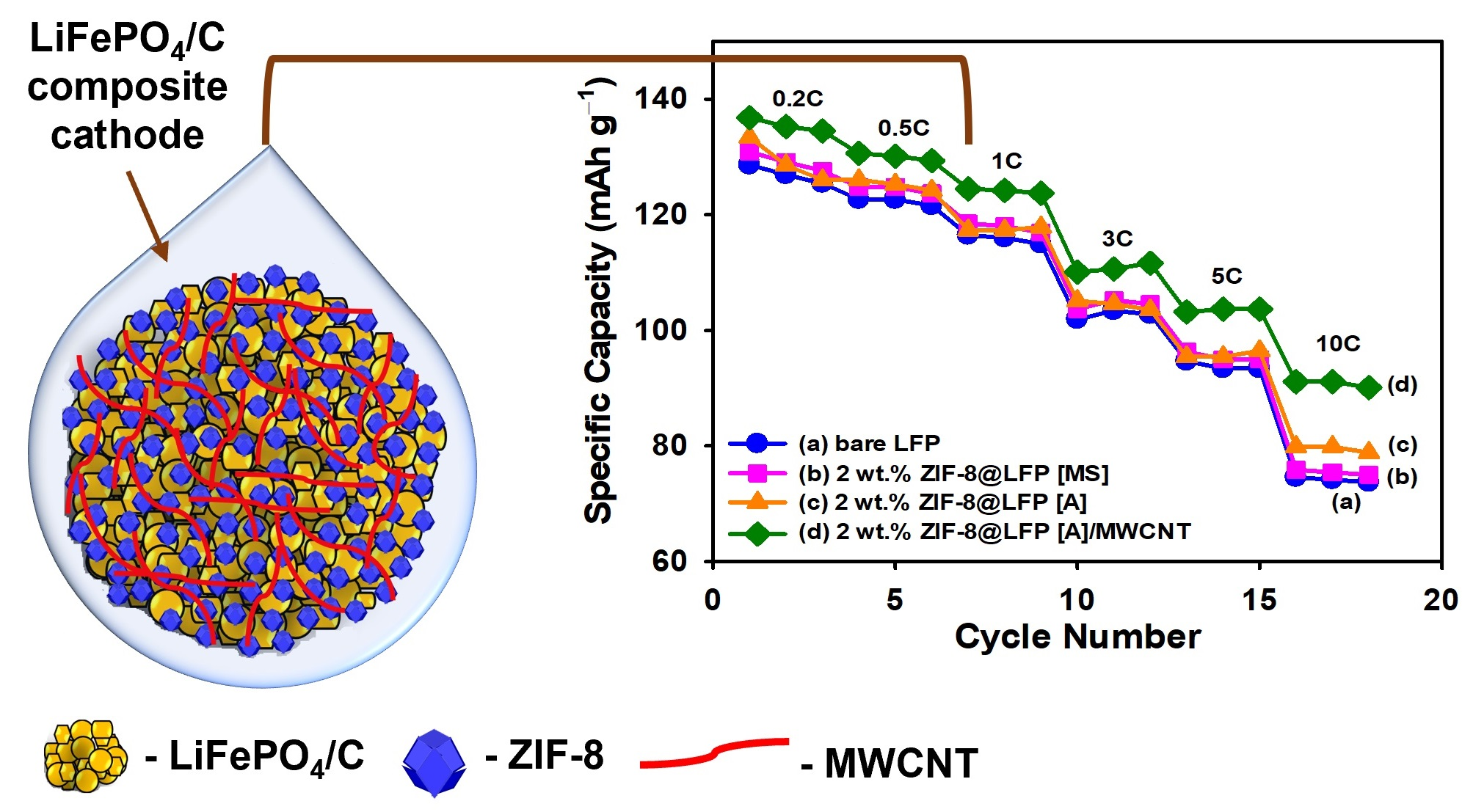
| 2 wt.% ZIF-8@LFP [A]/MWCNT | 125 | 110 | 103 | 91 | This work |
| Parameters | Rb (Ω) | Rct (Ω) | RT (Ω) (RT = Rb + Rct) | DLi+ (cm2 s−1) | |||||
|---|---|---|---|---|---|---|---|---|---|
| Sample | |||||||||
| Before | After | Before | After | Before | After | Before | After | ||
| Bare LFP | 4.18 | 6.56 | 426.49 | 401.21 | 430.67 | 407.77 | 2.22 × 10⁻¹⁴ | 3.40 × 10⁻¹⁴ | |
| 2 wt.% ZIF-8@LFP [MS] | 6.51 | 7.69 | 181.10 | 82.38 | 205.86 | 90.07 | 6.92 × 10⁻¹⁵ | 5.51 × 10⁻¹⁴ | |
| 2 wt.% ZIF-8@LFP [A] | 4.10 | 6.98 | 274.10 | 120.65 | 278.20 | 127.63 | 1.72 × 10⁻¹⁴ | 6.73 × 10⁻¹⁴ | |
| 2 wt.% ZIF-8@LFP [A]/MWCNT | 3.85 | 6.82 | 193.00 | 15.09 | 196.85 | 21.89 | 8.41 × 10⁻¹⁵ | 9.85 × 10⁻¹⁴ | |
Disclaimer/Publisher’s Note: The statements, opinions and data contained in all publications are solely those of the individual author(s) and contributor(s) and not of MDPI and/or the editor(s). MDPI and/or the editor(s) disclaim responsibility for any injury to people or property resulting from any ideas, methods, instructions or products referred to in the content. |
© 2023 by the authors. Licensee MDPI, Basel, Switzerland. This article is an open access article distributed under the terms and conditions of the Creative Commons Attribution (CC BY) license (https://creativecommons.org/licenses/by/4.0/).
Share and Cite
Mathur, P.; Shih, J.-Y.; Li, Y.-J.J.; Hung, T.-F.; Thirumalraj, B.; Ramaraj, S.K.; Jose, R.; Karuppiah, C.; Yang, C.-C. In Situ Metal Organic Framework (ZIF-8) and Mechanofusion-Assisted MWCNT Coating of LiFePO4/C Composite Material for Lithium-Ion Batteries. Batteries 2023, 9, 182. https://doi.org/10.3390/batteries9030182
Mathur P, Shih J-Y, Li Y-JJ, Hung T-F, Thirumalraj B, Ramaraj SK, Jose R, Karuppiah C, Yang C-C. In Situ Metal Organic Framework (ZIF-8) and Mechanofusion-Assisted MWCNT Coating of LiFePO4/C Composite Material for Lithium-Ion Batteries. Batteries. 2023; 9(3):182. https://doi.org/10.3390/batteries9030182
Chicago/Turabian StyleMathur, Priyatrisha, Jeng-Ywan Shih, Ying-Jeng James Li, Tai-Feng Hung, Balamurugan Thirumalraj, Sayee Kannan Ramaraj, Rajan Jose, Chelladurai Karuppiah, and Chun-Chen Yang. 2023. "In Situ Metal Organic Framework (ZIF-8) and Mechanofusion-Assisted MWCNT Coating of LiFePO4/C Composite Material for Lithium-Ion Batteries" Batteries 9, no. 3: 182. https://doi.org/10.3390/batteries9030182