
Textile PAN Carbon Fibers Cathode for High-Voltage Seawater Batteries
by
 , , , , and
João Ferreira
1,2,3,
Tiago Salgueiro
1,2,3,
Jossano Marcuzzo
4,
Eduardo Arruda
5,
João Ventura
2,3 and
Joana Oliveira
1,6,* 1
Department of Engineering Physics, Faculty of Engineering, University of Porto, 4200-465 Porto, Portugal
2
Department of Physics and Astronomy, Faculty of Science, University of Porto, 4169-007 Porto, Portugal
3
Institute of Physics for Advanced Materials, Nanotechnology and Photonics (IFIMUP), 4169-007 Porto, Portugal
4
JMHP—Consultoria em Materiais Ltda, Departamento de PDI, Jacarei 12301-600, SP, Brazil
5
Faculdade de Ciências e Tecnologia (FACET)/Química, Fundação Universidade Federal da Grande Dourados—UFGD Unidade II, Dourados 79804-970, MS, Brazil
6
Associate Laboratory for Energy, Transports and Aerospace (LAETA), INEGI, 4200-465 Porto, Portugal
*
Author to whom correspondence should be addressed.
Batteries 2023, 9(3), 178; https://doi.org/10.3390/batteries9030178
Submission received: 16 February 2023
/
Revised: 11 March 2023
/
Accepted: 16 March 2023
/
Published: 18 March 2023
(This article belongs to the Special Issue Anode and Cathode Materials for Lithium-Ion and Sodium-Ion Batteries)
Abstract
:Rechargeable sodium seawater batteries (SWBs) are gaining the world leadership of high voltage energy storage devices for marine environments. With natural seawater as the source of active material, SWBs can be supplied infinitely with Na cations. Because of their open-structured cathode, the cathode material’s specific surface area, porosity and wettability need to be optimized to achieve a high-performance cell. In this work, activated textile polyacrylonitrile (PAN) fibers were used to produce an activated carbon felt with a facile manufacturing process. The easy and low-cost production of these fibers makes them excellent candidates for energy storage applications involving oxygen evolution and reduction reactions. The electrochemical performance results of the fabricated activated PAN fibers and of commercial carbon felts were measured and compared, being characterized through galvanostic charge discharge cycles, electrochemical impedance spectroscopy and cyclic voltammetries. A performance improvement was observed with PAN activated carbon felt as half cell with a capacitance increase (about 9000%), and as full cell with a smaller voltage gap (about 10%) and increased gravimetric capacitance (about 260%) when compared to the commercial carbon felt. The successful implementation of PAN activated carbon felts in an aqueous environment opens new paths toward high performance seawater battery’s cathodes.
1. Introduction
Technological advances to mitigate the energy and environmental challenges that we presently face (such as our reliance on fossil fuel or global warming) are on the rise [1]. In particular, energy storage devices are the key solution for matching fluctuating electricity supply with demand [2], transforming renewable energy into a usable form. High-voltage rechargeable batteries are expected to have a major role for a low-carbon footprint and sustainable future. A key path toward sustainable and long-term technologies is the use of abundant materials with environmentally friendly extraction processes. In this regard, high-voltage rechargeable seawater batteries (SWBs) have been actively developed in the last two decades [1,2,3,4]. Oceans cover more than 70% of the Earth’s surface, being an abundant natural resource. SWBs use the abundant sodium ions present in natural seawater as an unlimited source of working ions without the need to store them in the electrodes. Their electrochemical energy is brought by the oxidation of seawater in the cathode and the reduction of sodium ions in the anode. Furthermore, the use of seawater as the catholyte leads to a strong reduction in material and manufacturing costs [1,2]. The fact that the SWB cell will be immersed in circulating seawater facilitates effective heat transfer from the cells, which excludes the need for internal active cooling systems. This eases the burden of thermal management and improves safety. SWBs can also be coupled with renewable energy sources, such as wind, solar or ocean motion energy, transforming renewable energy into usable electricity on demand [1,5,6,7,8].
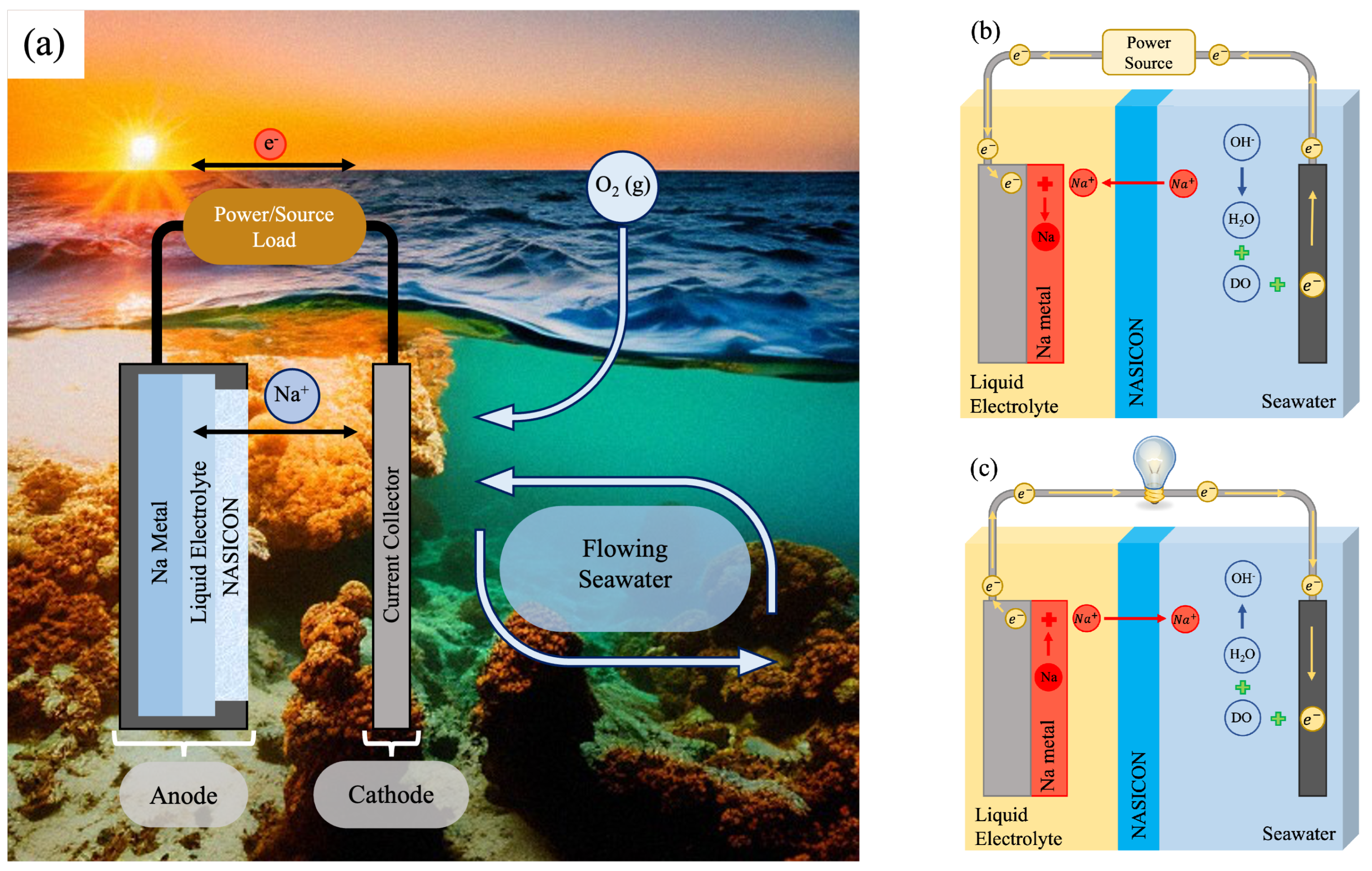
A SWB cell (Figure 1a) is the combination of an open-structured cathode with Na metal as the anode (with a potential of −2.73 V vs. standard hydrogen electrode (SHE)) creating a high voltage electrochemical cell. Separating these two components is NASICON (NA Super Ion CONductor, Na3Zr2Si2PO12), a sodium ion conducting membrane that only allows the passage of Na+, acting as a solid separator that prevents other ions from reaching the anode. Due to the high reactivity of the Na metal, the anode part is sealed, ensuring that only the separator is exposed to seawater. Inside the anode, the Na metal is attached to a current collector and immersed in a non-aqueous liquid electrolyte, used as a buffer layer between the Na metal and the solid separator to ensure good ionic conductivity and a stable Na deposition [1].
The open-structure configuration of the cathode allows for a continuous supply of fresh seawater, that is, the catholyte (being simultaneously the cathode and the electrolyte), during operation. The anode of a SWB cell uses sodium as the active material, while the cathode uses dissolved oxygen (DO). The oxygen evolution/reduction reaction (OER/ORR) is thermodynamically preferred over the chlorine evolution/reduction reaction (ClER/ClRR). However, the proportion of the two reactions depends on the operating conditions close to the cathode current collector. Considering the oxygen partial pressure at 100% from ambient air, the OER/ORR reactions will be preferential [4]. The half cell reactions of the cathode OER/ORR activity are given by
During the charging process (Figure 1b), Na+ ions travel to the anode via the NASICON and the liquid electrolyte. The non-aqueous liquid electrolyte, in contact with the Na metal, ensures that the sodium metal deposition/stripping is a stable and reversible process. When the SWB cell discharges (Figure 1c), the Na+ will travel back to the seawater, and the cathode ORR takes place. The reaction products will be taken away by flowing seawater, replacing them with new reactants for another charging process.
Depending on the cathode material, a capacitive contribution may be more or less relevant. If we use a supercapacitor-like electrode with a very high surface area as the cathode current collector (CCC), the formation of an electric double layer (EDL) with high capacitance will take place, which will improve the SWB cell performance [9]. In fact, the charge transport via EDL is much faster than the OER/ORR reactions and other faradaic processes. SWBs with high-capacity cathodes thus show increased overall capacity and reduced voltage gap.
In this respect, carbon felts (CFs) are widely used as cathodes for aqueous electrolyte batteries and play an important role in the development of clean energy storage and conversion technologies [10]. Nevertheless, SWBs with CFs as cathodes can show low efficiency and large voltage gaps because of the sluggish kinetics of the redox reactions [6,11,12,13,14]. To surpass these issues, activated carbon felts (ACFs) have also been used as CCCs with very high surface area and porosity, allowing a significant capacitive behavior through the formation of electrical double-layer capacitors (EDLCs). In addition, heat treatments and activation processes have been reported to populate the surface of the material with abundant surface-active functional groups (such as and ) that result in active OER/ORR sites, improving the efficiency of the reactions and providing a synergetic contribution [6,12,13,14,15,16].
In this work, ACFs were manufactured using heavy tow textile polyacrylonitrile (PAN) fibers. To activate the carbon felt, a facile manufacturing process was applied that solves problems associated with the transformation of activated carbon fibers in their textile form. The polyacrylonitrile (PAN) fiber ACF was here used for the first time as a cathode on an aqueous environment as the CCC of a seawater battery cell. The characteristics and performance of this cathode were analyzed through galvanostic charge/discharge cycles, cyclic voltammetries and electrochemical impedance spectroscopy. For comparison terms, a commercial carbon felt (CCF) was also studied.
2. Materials and Methods
The anode compartment of the studied SWB cell consists of a coin-cell (4ToOne [17]) composed by a bottom, a spring, a spacer with Na metal (with 99.9% purity), a non-aqueous liquid electrolyte (LE) [1 M NaCF3SO3 in TEGDME (tetraethylene glycol dimethylether)], a solid electrolyte (NASICON), and a cap. The Na metal is isolated from seawater through the NASICON separator that enables the selective transfer of Na+ ions between the two electrodes. The NASICON is stable in seawater and in the liquid electrolyte [3].
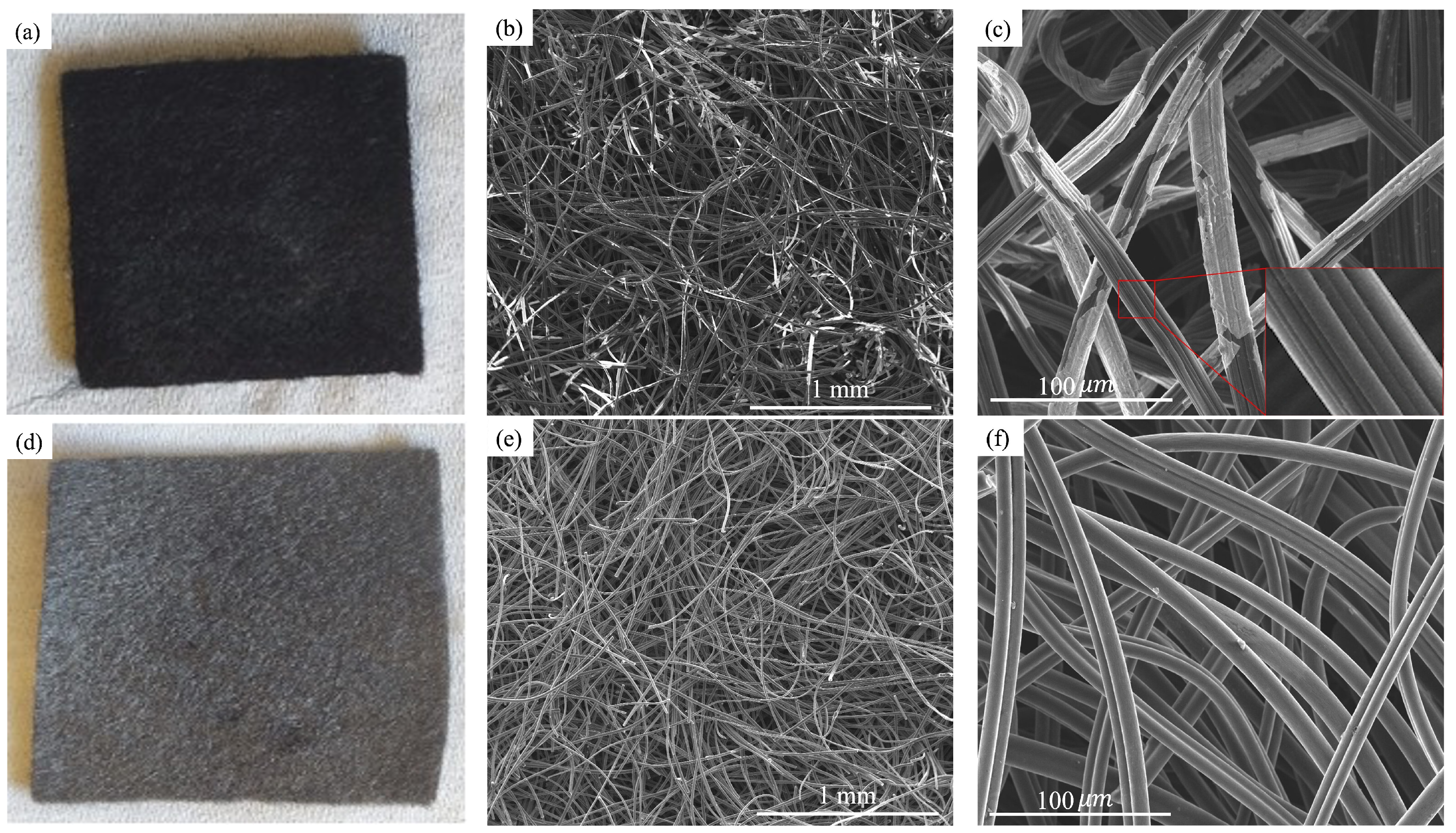
The cathode side consists of the catholyte (seawater), a CCC and a titanium string. The catholyte was synthesized to mimic the composition of natural seawater’s salt concentration of 0.6 M of NaCl [18]. Two CCC were studied, a commercial carbon felt (CCF; from Alfa Aesar) (Figure 2a) and the activated textile PAN fiber carbon felt (ACF; Figure 2d). The CCF has a thickness of 1.90 mm and a surface area of 0.6 m2 g−1. The ACF has a thickness of 0.72 mm and a surface area of 1200 m2 g−1. The used CCF thickness is three times larger than the produced ACF. For thickness comparison reasons, three layers of ACF were therefore used.
The complete fabrication procedure of the new textile PAN fiber (manufacture and activation) can be found in Ref. [19]. Succinctly, a heavy tow of 5.0 dtex textile PAN fibers was used as raw material for the ACF preparation (Figure S1 [20] in Supplementary Materials). In the first step, the tow was oxidized in a laboratory scale oven until flame resistance condition. In the second step, the heavy tow (now oxidized) was cut in 60 mm fibers and, by standard textile needling processes converted in felt with about 200 gm−2. In the third step, the felt was placed inside a furnace and carbonized at 900 °C in an argon atmosphere. The carbonization step is a pyrolysis step, so it should occur in an inert atmosphere. Here, Ar (although any other inert gas, such as N2 or He, could be used) was used to convert the carbonaceous raw material into a more stable and heat-resistant compound that consists mainly of carbon (C). Oxygen and hydrogen are largely eliminated, thus leaving a carbonaceous framework with low surface area. After carbonization, and for the activation process, the gas was shifted to carbon dioxide at a flow of 200 sccm and the temperature increased to 1000 °C for 50 min. During the activation, CO2 reacts with the carbon fibers and removes some of the carbon atoms from the fibers, converting them into CO that will be carried away by the flowing gas, enhancing the porosity and specific surface area of the carbon fibers. At the end of the activation step, the gas was again shifted to argon and the temperature cooled to room temperature. The characterization by nitrogen isotherm at 77 K show a micro porous material with type I isotherm with about 1200 m2 g−1 [19,21]. This manufacturing process solves the difficulty regarding the transformation of activated carbon fibers in their textile form to create a felt because the carbonization and activation part of the process is only performed after the oxidized PAN fibers are transformed in their textile form [21].
The SWB cell performance was measured in a testing setup (4ToOne [17]), that allows the regulation of the water flux. A potentiostat (model Gamry 5000) was connected to this setup allowing for electrochemical tests to be performed to the full seawater cell. The electrochemical tests were performed using two and three electrode configurations. In the three electrode configuration, a planar platinum wire electrode was used as the counter electrode and the reference electrode was silver/silver chloride (Ag/AgCl). With this configuration, cyclic voltammetries (with a scan rate of 1.5 mV s−1) and electrochemical impedance spectroscopy (EIS) were performed. In the two electrode configuration, the Na metal coin-cell was used as the counter and reference electrodes. The electrochemical characterization performed with this configuration consisted of galvanostic cyclic charge/discharge voltage profiles and cyclic voltammetries (with a scan rate of 1.5 mV s−1 and a potential window from 2.5 to 4.0 V). The morphological and chemical characterization of the different CCC surfaces was performed using scanning electron microscopy (SEM) and energy dispersive X-ray spectroscopy (EDS), and the wettability of each CCC was assessed using the sessile drop method.
3. Results and Discussion
3.1. Morphological and Chemical Characterization
The CCF surface is composed of a large number of randomly distributed microfibers. The microfibers have a diameter of 15 to 20 μm, displaying a slit-shaped pore structure on their surface (Figure 2b,c and Figure S2). Through EDS analysis (Figure S3), we were able to identify the partial white coating on the CCF fibers as sodium chloride (NaCl) that was deposited during charge/discharge cycles.
The PAN fiber ACF has a non-uniform microfiber distribution, much like CCF. The ACF has smaller microfibers with diameters ranging from 8 to 11 μm and increased fiber density (Figure 2e,f and Figure S4). The smaller fiber diameter, when compared to CCF, results in a much higher surface area [22]. The SEM images of the ACF do not reveal the white spots associated with NaCl deposition during charge/discharge cycles, unlike in the CCF SEM images. CCFs contain sizing agents for mechanical reinforcement, which reduce the surface area and decrease the wettability of the surface. Nevertheless, the high level of NaCl deposition in the CCF and absence of NaCl in ACF suggests that the presence of the polymer could influence the amount of NaCl deposited during charge/discharge cycles. Another explanation is the pore size. The larger the pores, the higher the volume available for the deposition of reaction products or electrolyte reduction species [23].
3.2. Wettability
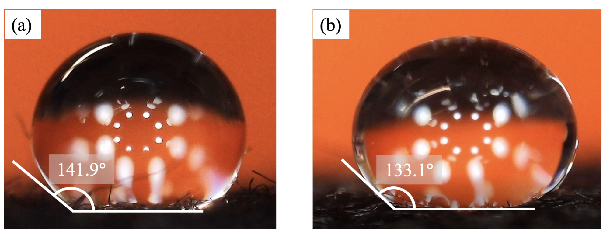
The wettability of the CCCs is another parameter that can influence the performance of a seawater cell, being measured with the contact angle (Figure 3).
Poor wettability can lead to irregular reaction rates and a slight decrease in the available surface area in the electrodes. Thus, wettability measurements were performed before and after charge/discharge cycles (Table 1), allowing to observe possible changes in the hydrophobic/hydrophilic behaviors.
CCF reveals poor wettability before utilization (contact angle of 141.9°) because of the mechanical reinforcement polymer. After charge/discharge cycles, the wettability was again measured, revealing a significant improvement, with a fast absorption of the water drop (0.25 s) that prevents the measurement of the contact angle. This increase in wettability is likely due to the deposition of NaCl in the fibrous surface of the CCF. NaCl is a wetting agent that can reduce the surface tension and, consequently, improve the wettability [24]. Therefore, CCF becomes significantly more hydrophilic with NaCl deposited as a wetting agent. The same does not apply to the ACF-PAN fiber. ACF is more hydrophobic than CCF before and after charge/discharge cycles. This supports the SEM analysis, where no relevant amount of deposited NaCl was observed in the fibrous surface of the CCC, maintaining its hydrophobic behavior (Figure 2).
3.3. Cathodes Electrochemical Characterization
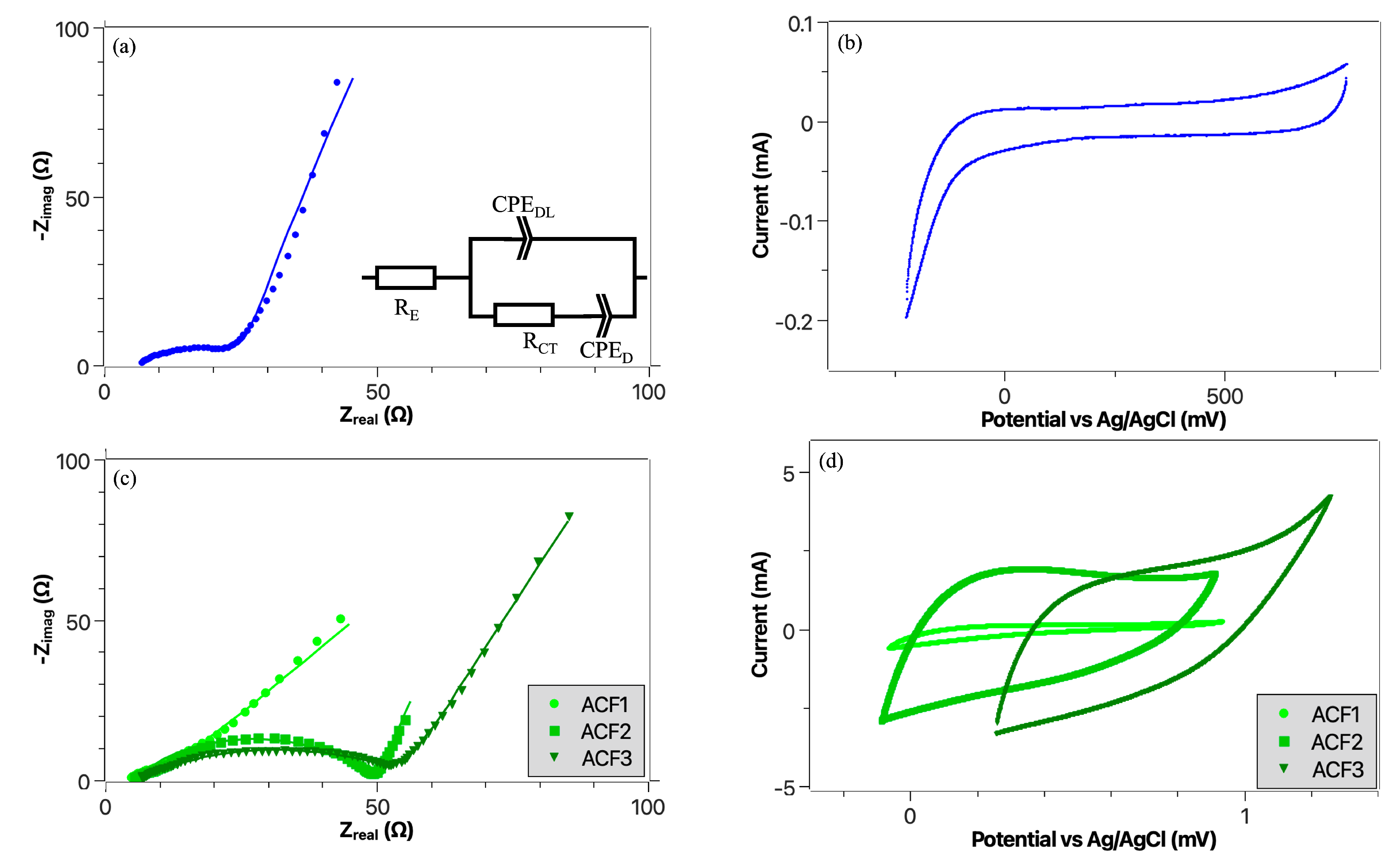
Figure 4a shows the EIS spectrum for the CCF, obtained with a three electrode configuration, where a flattened semi-circle for higher frequencies can be observed. In Figure 4b, the cyclic voltammetry analysis is shown for the CCF. It is possible to note a well-defined electrochemical stability window (ESW), without significant redox reactions. The small area inside the ESW traduces a small capacitive contribution. The EIS spectra obtained for one (ACF1), two (ACF2) and three (ACF3) layers of ACF are presented in Figure 4c. We can see that increasing the number of ACF layers increases both the CCC capacitance and resistance, corresponding to a larger charge transfer impedance [23], by increasing the available surface area, porosity and fiber content. This can also be seen in the cyclic voltammetries obtained in Figure 4d, by the significant increase in the capacitance of the CCC with increasing number of layers. Furthermore, the ACF3 curve shows a slight tilting when compared to ACF2 due to the resistance increase, also seen in the corresponding EIS spectra.
The capacitance (C) was calculated from the CVs as
where Q is the amount of charge (given by the area within the cyclic voltammetry curve) and ΔV is the voltage window used in the cyclic voltammetries. Table 2 presents the obtained capacitance values and the relative increase with respect to the capacitance of the CCF. An outstanding capacitance increase of almost 100× is obtained with the addition of the PAN textile activated carbon felt layers.
Equivalent Circuit
The EIS spectra of the CCF, ACF1, ACF2 and ACF3 cathodes were analyzed and fitted (Figure 4a,c) with a similar equivalent circuit (inset of Figure 4a). The first resistor (RE) is associated with the electrolyte and titanium wire resistance. A semi-circle that is associated with the charge transfer resistance (RCT) in parallel with the electric double layer capacitance (CPEDL) of the carbon fibers is observed in all spectra. A constant phase element (CPE), instead of a capacitor, is considered because of the highly porous structure of the CCCs. In the case of the CCF spectrum, besides being associated with the charge transfer, RCT could also be related with the extra NaCl layer deposited on the surface of the carbon fibers during charge/discharge cycles, and with the mechanical reinforcement polymer. This extra resistance is not present in the PAN textile ACF cathodes since no relevant amount of NaCl was detected, and the manufacturing process does not include a mechanical reinforcement polymer. At lower frequencies, a quasi-linear constant phase element (CPED) is observed in all spectra, associated with a dominant mass transport of the diffusion process. The equivalent circuit fits well the EIS data in the semi-circles, with small deviations in the CPED. The small deviations in the low-frequency range of CCF (Figure 4a) are due to the untidy transition between the semi-circle and the diffusion straight line. The fitting parameters for each component are presented in Table 3. As expected, RE is similar in the four spectra since it is associated with the same bulk electrolyte. The total resistance (RE + RCT) is, as expected, larger for CCF (28.7 Ω) than for ACF1 (19.4 Ω) because of the extra resistance mentioned above. When ACF layers are added (ACF2 and ACF3), the total resistance increases, with ACF3 being the one with the highest total resistance (56.6 Ω).
The impedance of a constant phase element (CPE) can be defined by
where is the angular frequency and Y0 and n are the characteristic parameters of the CPE. If n is between 0.8 and 1, CPE can be approximated as a capacitor with some capacitance dispersion, associated with the surface roughness. The four used cathodes have surfaces with a high degree of roughness, due to a non-uniform fiber distribution with strong deviations from an ideal capacitor behavior [25,26]. From Table 3, it is possible to observe that all cathodes have an n value outside this 0.8–1 range, so their capacitances cannot be precisely determined from EIS analysis.
3.4. Full Cell Electrochemical Analysis
The CCF and ACF3, with similar thicknesses, were then tested in a seawater battery full cell, with a two electrode configuration (Na/LE/NASICON/seawater/CCC). A significant improvement of the capacitive behavior and of the performance of the SWB cell using ACF3 is observed.
3.4.1. Galvanostic Voltage Profiles
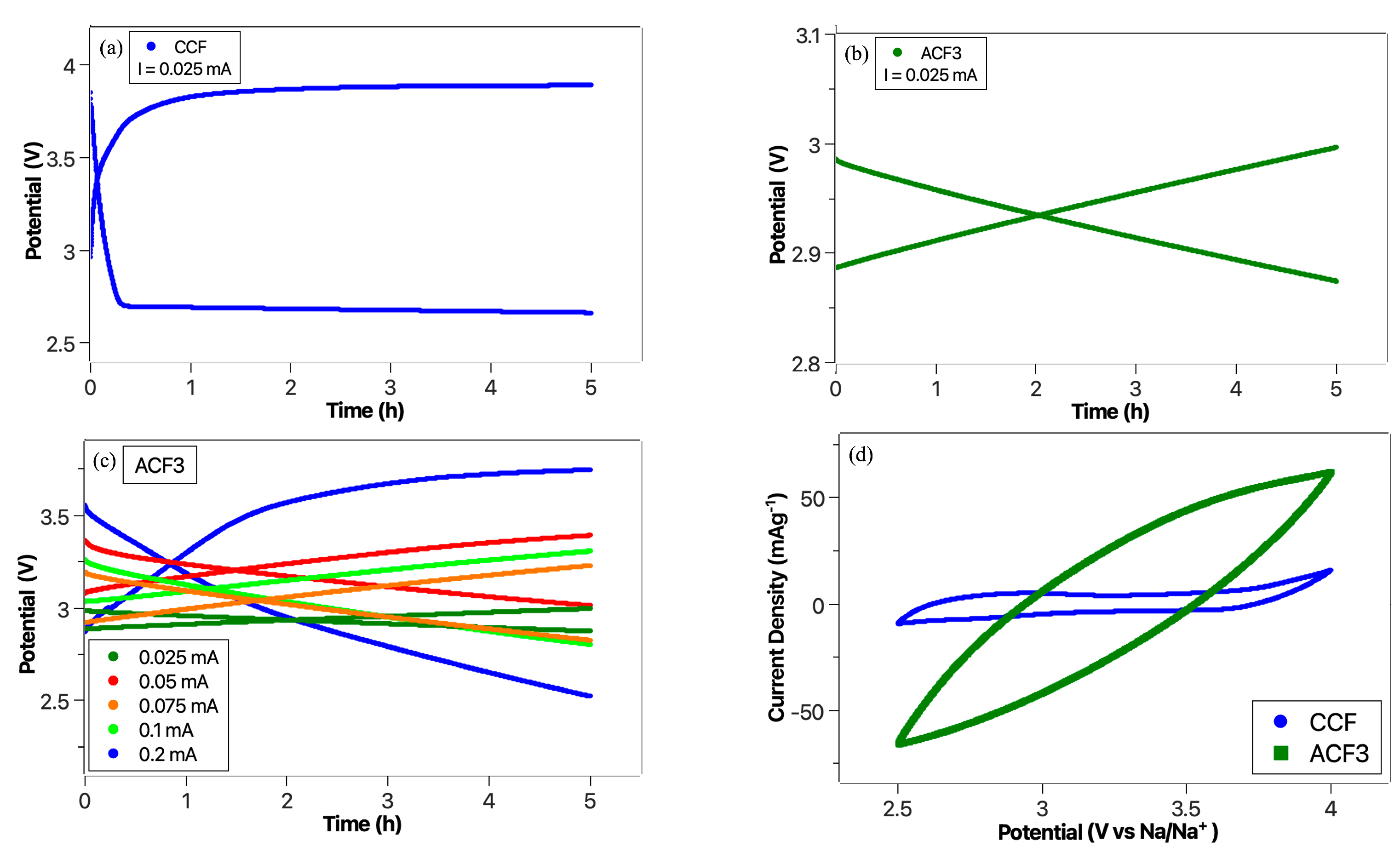
Figure 5a shows the voltage profile with a large voltage gap (1.23 V) for CCF. The plateau is reached in a short period of time, both in charge and discharge, corresponding to a very high activation polarization effect [27]. The redox reactions taking place at the electrodes are the main working mechanism operating. The dominant reactions are OER/ORR, corresponding to a theoretical electrochemical potential of 3.48 V. Overpotentials of 0.41 V in the charge and 0.82 V in the discharge, after 5 h, are observed. On the other hand, the ACF3 charge profile ends at 5 h with 3.00 V, whereas the discharge ends at 5 h with 2.87 V, resulting in a very small voltage gap (0.13 V), i.e., about 10% of that of the CCF (Figure 5b). The absence of the polymer in the ACF manufacturing process is relevant for this substantial voltage gap reduction. Besides the high surface area, another reason for the enhanced ACF performance comes from its activation step with CO2, where the surface of the fibers is populated with abundant oxygen functional groups, namely and , that result in excellent sites improving the OER/ORR activity efficiency [28].
3.4.2. Current Variation
The charge and discharge profile of the SWB cell with ACF3 was then measured for currents ranging from 0.025 mA to 0.2 mA (Figure 5c). As expected, a higher current results in an increase in the voltage gap and activation polarization effect. The redox reactions are a slow process and, with low currents, the equilibrium is more easily achieved. Since the amount of active sites does not depend on the current, there will be an accumulation of ions in the carbon matrix at higher current densities, which results in an increase in the CCC resistance [29]. The only cycle whose asymptotic overpotential can be observed is the 0.2 mA, which ends at 3.75 V, with an overpotential of 0.27 V. The discharge for the same current ends at 2.52 V with an overpotential of 0.96 V.
3.4.3. Cyclic Voltammetry
CCF cyclic voltammetry analysis is presented in Figure 5d. It is possible to see that, although redox reactions may be present, they are not the dominant factor within the electrochemical stability window [30]. The current density refers to the amount of active material in the anode (36 mg of Na metal). On the other hand, the CV for ACF3 (Figure 5d) is substantially different from the CCF one. In the ACF3 case, it is harder to identify the onset potentials associated with the faradaic reactions, with a dominant capacitive effect originated by the increase in the specific surface area. Nonetheless, the pseudo-oval shape of this CV curve indicates that there is in fact an extra resistive component. The extra resistance has two possible origins, the three layers of ACF used to reach a thickness similar to that of CCF and ACF3 poorer wettability. Although this extra resistive component changes the CV shape to a pseudo-oval, a significant capacitive contribution is responsible for the obtained low voltage gap and activation polarization effect [31]. We calculated the relative variation of the gravimetric capacitance due to the difficulty in isolating the cathode capacitance contribution in the full cell configuration. A 260% capacitance increase was observed. Both gravimetric capacitances were calculated by excess (CCF; 6.7 F g−1 and ACF; 24.3 F g−1, for 36 mg of sodium metal as the active material at the anode).
4. Conclusions
The performance of a high-voltage rechargeable seawater cell with different cathodes was studied and analyzed. The cathodes used were a commercial carbon felt and an activated carbon felt. The ACF was fabricated from oxidized textile PAN fibers that were transformed in their textile form before carbonization and activation, leading to high specific surface area and the absence of non-conductive binding polymers. These PAN textile ACFs were applied for the first time with aqueous electrolytes, and a considerable capacitance increase, both as half cell (i.e., about 9000%, from 26.9 mF (CCF) to 2521.6 mF (ACF3)) and as full cell (i.e., about 260%, from 6.7 F g−1 (CCF) to 24.3 F g−1 (ACF3)) was observed, with a voltage gap decrease (i.e., about 10%). PAN fibers activated carbon felts, with an easier manufacturing process resulted in a significant performance improvement of seawater batteries, while also solving one of the problems associated with commercial fabrication of ACFs, that is the transformation of activated fibers in their textile form. To our understanding, the results show that the effect of increasing the effective surface area of ACF by not including the non-conductive binder polymer in its fabrication process is largely dominant over the effect of ACF loss of wettability due to the difficulty of NaCl deposition that itself results from the absence of the same polymer. The manufacturing method removes the need to add a mechanical reinforcement polymer, simplifying and improving the scalability of the fabrication process. This also increases the SWB scalability and versatility, creating new opportunities for their application.
Supplementary Materials
The following supporting information can be downloaded at: https://www.mdpi.com/article/10.3390/batteries9030178/s1, Figure S1: SEM image of a single fiber of the commercial PAN precursor before any treatment was applied at a 5 μm magnification [20]; Figure S2: SEM image of the CCF carbon fibers with a 200 μm magnification; Figure S3: EDS analysis of the white spots on the surface of the CCF carbon fibers; Figure S4: SEM image of the ACF carbon fibers with a 200 μm magnification.
Author Contributions
Conceptualization, J.O., J.V. and J.F.; methodology, J.F., J.O. and J.V.; validation, J.O. and J.V.; formal analysis, J.F. and J.O.; investigation, J.F., J.O., T.S., J.M., E.A. and J.V.; resources, J.O., J.V., J.M. and E.A.; data curation, J.F., J.O., T.S. and J.V.; writing—original draft preparation, J.F., J.O., J.M. and E.A.; writing—review and editing, J.F., J.O. and J.V.; supervision, J.O. and J.V. All authors have read and agreed to the published version of the manuscript.
Funding
This work was funded by FEDER funds through the COMPETE 2020 Program and National Funds through FCT—Portuguese Foundation for Science and Technology under UID/NAN/50024/2019. The author JO would like to acknowledge the Portuguese Foundation for Science and Technology (FCT) for its financial support via the UIDP/50022/2020 project (LAETA Programmatic Funding).
Data Availability Statement
Not applicable.
Conflicts of Interest
The authors declare no conflict of interest.
References
- Hwang, S.M.; Park, J.S.; Kim, Y.; Go, W.; Han, J.; Kim, Y.; Kim, Y. Rechargeable seawater batteries—From concept to applications. Adv. Mater. 2019, 31, 1804936. [Google Scholar] [CrossRef]
- Senthilkumar, S.; Go, W.; Han, J.; Thuy, L.P.T.; Kishor, K.; Kim, Y.; Kim, Y. Emergence of rechargeable seawater batteries. J. Mater. Chem. A 2019, 7, 22803–22825. [Google Scholar] [CrossRef]
- Kim, Y.; Lee, W.G. Seawater Batteries: Principles, Materials and Technology; Springer Nature: Singapore, 2022. [Google Scholar]
- Han, J.; Hwang, S.M.; Go, W.; Senthilkumar, S.; Jeon, D.; Kim, Y. Development of coin-type cell and engineering of its compartments for rechargeable seawater batteries. J. Power Sources 2018, 374, 24–30. [Google Scholar] [CrossRef]
- Hwang, S.M.; Kim, J.; Kim, Y.; Kim, Y. Na-ion storage performance of amorphous Sb2S3 nanoparticles: Anode for Na-ion batteries and seawater flow batteries. J. Mater. Chem. A 2016, 4, 17946–17951. [Google Scholar] [CrossRef]
- Manikandan, P.; Kishor, K.; Han, J.; Kim, Y. Advanced perspective on the synchronized bifunctional activities of P2-type materials to implement an interconnected voltage profile for seawater batteries. J. Mater. Chem. A 2018, 6, 11012–11021. [Google Scholar] [CrossRef]
- Senthilkumar, S.; Abirami, M.; Kim, J.; Go, W.; Hwang, S.M.; Kim, Y. Sodium-ion hybrid electrolyte battery for sustainable energy storage applications. J. Power Sources 2017, 341, 404–410. [Google Scholar] [CrossRef]
- Kim, J.K.; Mueller, F.; Kim, H.; Jeong, S.; Park, J.S.; Passerini, S.; Kim, Y. Eco-friendly Energy Storage System: Seawater and Ionic Liquid Electrolyte. ChemSusChem 2016, 9, 42–49. [Google Scholar] [CrossRef]
- Park, J.; Park, J.S.; Senthilkumar, S.; Kim, Y. Hybridization of cathode electrochemistry in a rechargeable seawater battery: Toward performance enhancement. J. Power Sources 2020, 450, 227600. [Google Scholar] [CrossRef]
- Qiao, Y.; Zhang, C.; Kong, F.; Zhao, Q.; Kong, A.; Shan, Y. Activated biochar derived from peanut shells as the electrode materials with excellent performance in Zinc-air battery and supercapacitance. Waste Manag. 2021, 125, 257–267. [Google Scholar] [CrossRef]
- Kim, K.; Hwang, S.M.; Park, J.S.; Han, J.; Kim, J.; Kim, Y. Highly improved voltage efficiency of seawater battery by use of chloride ion capturing electrode. J. Power Sources 2016, 313, 46–50. [Google Scholar] [CrossRef]
- Suh, D.H.; Park, S.K.; Nakhanivej, P.; Kim, Y.; Hwang, S.M.; Park, H.S. Hierarchically structured graphene-carbon nanotube-cobalt hybrid electrocatalyst for seawater battery. J. Power Sources 2017, 372, 31–37. [Google Scholar] [CrossRef]
- Senthilkumar, S.; Park, S.O.; Kim, J.; Hwang, S.M.; Kwak, S.K.; Kim, Y. Seawater battery performance enhancement enabled by a defect/edge-rich, oxygen self-doped porous carbon electrocatalyst. J. Mater. Chem. A 2017, 5, 14174–14181. [Google Scholar] [CrossRef]
- Jeoung, S.; Sahgong, S.H.; Kim, J.H.; Hwang, S.M.; Kim, Y.; Moon, H.R. Upcycling of nonporous coordination polymers: Controllable-conversion toward porosity-tuned N-doped carbons and their electrocatalytic activity in seawater batteries. J. Mater. Chem. A 2016, 4, 13468–13475. [Google Scholar] [CrossRef]
- Ryu, J.H.; Park, J.; Park, J.; Mun, J.; Im, E.; Lee, H.; Hong, S.Y.; An, K.; Lee, G.; Kim, Y.; et al. Carbothermal shock-induced bifunctional Pt-Co alloy electrocatalysts for high-performance seawater batteries. Energy Storage Mater. 2022, 45, 281–290. [Google Scholar] [CrossRef]
- Bezerra, L.S.; Maia, G. Developing efficient catalysts for the OER and ORR using a combination of Co, Ni, and Pt oxides along with graphene nanoribbons and NiCo2O4. J. Mater. Chem. A 2020, 8, 17691–17705. [Google Scholar] [CrossRef]
- 4 TO ONE. 2022. Available online: https://www.4toone.com/main/ (accessed on 17 March 2023).
- Son, M.; Park, S.; Kim, N.; Angeles, A.T.; Kim, Y.; Cho, K.H. Simultaneous energy storage and seawater desalination using rechargeable seawater battery: Feasibility and future directions. Adv. Sci. 2021, 8, 2101289. [Google Scholar] [CrossRef] [PubMed]
- Amaral, M.A.d.; Matsushima, J.T.; Rezende, M.C.; Gonçalves, E.S.; Marcuzzo, J.S.; Baldan, M.R. Production and characterization of activated carbon fiber from textile PAN fiber. J. Aerosp. Technol. Manag. 2017, 9, 423–430. [Google Scholar] [CrossRef]
- Saldanha Marcuzzo, J.; Otani, C. Fibra de Carbono Ativada-Produção Ultrarrápida a Partir da PAN Têxtil: Uma Abordagem da Produção e Caracterização de Fibra de Carbono Ativada a Partir de Matéria Prima Têxtil, 1st ed.; Novas Edições Acadêmicas: Saarbrücken, Germany, 2015; OCLC: 913015440. [Google Scholar]
- Marcuzzo, J.; Cuña, A.; Tancredi, N.; Polidoro, H.; Otani, S.; Otani, C. Microporous Activated Carbono Fiber Felt Produced from Brasilian Textile Pan Fiber; X Encontro Brasileiro sobre Adsorção: Guarujá, Brazil, 2014. [Google Scholar]
- Ko, F.K.; Yang, H. Functional nanofibre: Enabling material for the next generations smart textiles. J. Fiber Bioeng. Inform. 2008, 1, 81–92. [Google Scholar]
- Mirzaeian, M.; Hall, P.J. Characterizing capacity loss of lithium oxygen batteries by impedance spectroscopy. J. Power Sources 2010, 195, 6817–6824. [Google Scholar] [CrossRef]
- Guanhua, N.; Qian, S.; Meng, X.; Hui, W.; Yuhang, X.; Weimin, C.; Gang, W. Effect of NaCl-SDS compound solution on the wettability and functional groups of coal. Fuel 2019, 257, 116077. [Google Scholar] [CrossRef]
- Kim, C.H.; Pyun, S.I.; Kim, J.H. An investigation of the capacitance dispersion on the fractal carbon electrode with edge and basal orientations. Electrochim. Acta 2003, 48, 3455–3463. [Google Scholar] [CrossRef]
- Chang, B.Y. Conversion of a constant phase element to an equivalent capacitor. J. Electrochem. Sci. Technol. 2020, 11, 318–321. [Google Scholar] [CrossRef]
- Winter, M.; Brodd, R.J. What are batteries, fuel cells, and supercapacitors? Chem. Rev. 2004, 104, 4245–4270. [Google Scholar] [CrossRef] [PubMed] [Green Version]
- Kim, K.J.; Lee, S.W.; Yim, T.; Kim, J.G.; Choi, J.W.; Kim, J.H.; Park, M.S.; Kim, Y.J. A new strategy for integrating abundant oxygen functional groups into carbon felt electrode for vanadium redox flow batteries. Sci. Rep. 2014, 4, 1–6. [Google Scholar] [CrossRef] [Green Version]
- Pandey, L.; Sarkar, S.; Arya, A.; Sharma, A.; Panwar, A.; Kotnala, R.; Gaur, A. Fabrication of activated carbon electrodes derived from peanut shell for high-performance supercapacitors. Biomass Convers. Biorefinery 2021, 1–10. [Google Scholar] [CrossRef]
- Mogensen, R. Realization of Sodium-ion Batteries: From Electrode to Electrolyte Materials. Ph.D. Thesis, Acta Universitatis Upsaliensis, Uppsala, Sweden, 1941. [Google Scholar]
- El-Deen, A.G.; Choi, J.H.; Khalil, K.A.; Almajid, A.A.; Barakat, N.A. A TiO2 nanofiber/activated carbon composite as a novel effective electrode material for capacitive deionization of brackish water. RSC Adv. 2014, 4, 64634–64642. [Google Scholar] [CrossRef]
Figure 1.
Scheme of a seawater battery (SWB) cell (a) structure and operating mechanism during the (b) charge and the (c) discharge processes.
Figure 1.
Scheme of a seawater battery (SWB) cell (a) structure and operating mechanism during the (b) charge and the (c) discharge processes.

Figure 2.
Photographs of the used carbon felts: (a) commercial (CCF) and (d) activated (ACF) and their SEM images: CCF surface at (b) 1 mm and (c) 100 μm scales, where the white regions are the NaCl deposited, and ACF surface at (e) 1 mm and (f) 100 μm scales.
Figure 2.
Photographs of the used carbon felts: (a) commercial (CCF) and (d) activated (ACF) and their SEM images: CCF surface at (b) 1 mm and (c) 100 μm scales, where the white regions are the NaCl deposited, and ACF surface at (e) 1 mm and (f) 100 μm scales.

Figure 3.
Scheme of the contact angles of the drops used to measure the wettability on top of the (a) CCF and (b) ACF.
Figure 3.
Scheme of the contact angles of the drops used to measure the wettability on top of the (a) CCF and (b) ACF.

Figure 4.
Electrochemical impedance spectroscopy (EIS) fitted spectrum and cyclic voltammetry of CCF ((a,b), respectively) and of ACF with one (ACF1), two (ACF2) and three (ACF3) layers ((c,d), respectively), in a three electrode configuration [Pt/(Ag/AgCl)/CCC] in a seawater solution.
Figure 4.
Electrochemical impedance spectroscopy (EIS) fitted spectrum and cyclic voltammetry of CCF ((a,b), respectively) and of ACF with one (ACF1), two (ACF2) and three (ACF3) layers ((c,d), respectively), in a three electrode configuration [Pt/(Ag/AgCl)/CCC] in a seawater solution.

Figure 5.
Galvanostic charge–discharge cycles of a SWB cell with (a) CCF and (b) ACF3, at a current of 0.025 mA, (c) charge–discharge profiles of a SWB cell with ACF3 at different currents with a 5 h duration, in a two electrode connection, and (d) cyclic voltammetries of a SWB cell with CCF and ACF3.


Table 1.
Contact angle and absorption time of each cathode current collector (CCC) before and after charge/discharge cycles, where unmeasurable means that the drop was too rapidly absorbed.
Table 1.
Contact angle and absorption time of each cathode current collector (CCC) before and after charge/discharge cycles, where unmeasurable means that the drop was too rapidly absorbed.
| Cathode | Contact Angle (°) | Absorption Time (s) | |
|---|---|---|---|
| CCF | Unused | 141.9 | No Absorption |
| Used | Unmeasurable | 0.25 | |
| ACF | Unused | 133.1 | 137.6 |
| Used | 134.9 | 42.1 | |
Table 2.
Capacitance of the commercial carbon felt (CCF) and of the layered activated carbon felt (ACF).
Table 2.
Capacitance of the commercial carbon felt (CCF) and of the layered activated carbon felt (ACF).
| Cathode | Capacitance (mF) | Increase (%) | |
|---|---|---|---|
| CCF | 26.9 | - | |
| 1 Layer | 186.0 | 590.5 | |
| ACF | 2 Layers | 1920.0 | 7026.5 |
| 3 Layers | 2521.6 | 9258.7 | |
Table 3.
Equivalent circuit parameters for the fitted electrochemical impedance spectroscopy (EIS) data with a Pt/Seawater/(Ag/AgCl)/CCC configuration.
Table 3.
Equivalent circuit parameters for the fitted electrochemical impedance spectroscopy (EIS) data with a Pt/Seawater/(Ag/AgCl)/CCC configuration.
| CCC | Parameters | |||||
|---|---|---|---|---|---|---|
| RE () | RCT () | CPEDL (S · sn) | CPED (S · sn) | |||
| Y0 | n | Y0 | n | |||
| CCF | 6.366 | 22.33 | 665.0 × 10⁻⁶ | 0.556 | 2.320 × 10⁻³ | 0.882 |
| ACF1 | 3.805 | 15.64 | 504.3 × 10⁻⁶ | 0.583 | 849.3 × 10⁻⁶ | 0.623 |
| ACF2 | 5.000 | 45.00 | 390.3 × 10⁻⁶ | 0.666 | 400.0 × 10⁻³ | 0.840 |
| ACF3 | 5.835 | 50.80 | 2.054 × 10⁻³ | 0.462 | 334.7 × 10⁻³ | 0.776 |
Disclaimer/Publisher’s Note: The statements, opinions and data contained in all publications are solely those of the individual author(s) and contributor(s) and not of MDPI and/or the editor(s). MDPI and/or the editor(s) disclaim responsibility for any injury to people or property resulting from any ideas, methods, instructions or products referred to in the content. |
© 2023 by the authors. Licensee MDPI, Basel, Switzerland. This article is an open access article distributed under the terms and conditions of the Creative Commons Attribution (CC BY) license (https://creativecommons.org/licenses/by/4.0/).
Share and Cite
MDPI and ACS Style
Ferreira, J.; Salgueiro, T.; Marcuzzo, J.; Arruda, E.; Ventura, J.; Oliveira, J. Textile PAN Carbon Fibers Cathode for High-Voltage Seawater Batteries. Batteries 2023, 9, 178. https://doi.org/10.3390/batteries9030178
AMA Style
Ferreira J, Salgueiro T, Marcuzzo J, Arruda E, Ventura J, Oliveira J. Textile PAN Carbon Fibers Cathode for High-Voltage Seawater Batteries. Batteries. 2023; 9(3):178. https://doi.org/10.3390/batteries9030178
Chicago/Turabian StyleFerreira, João, Tiago Salgueiro, Jossano Marcuzzo, Eduardo Arruda, João Ventura, and Joana Oliveira. 2023. "Textile PAN Carbon Fibers Cathode for High-Voltage Seawater Batteries" Batteries 9, no. 3: 178. https://doi.org/10.3390/batteries9030178
Note that from the first issue of 2016, this journal uses article numbers instead of page numbers. See further details here.