Article

Ion Transport Regulated Lithium Metal Batteries Achieved by Electrospun ZIF/PAN Composite Separator with Suitable Electrolyte Wettability

Gansu Natural Energy Research Institute, International Solar Energy Center, Lanzhou 730046, China
*
Author to whom correspondence should be addressed.
Batteries 2023, 9(3), 166; https://doi.org/10.3390/batteries9030166
Submission received: 20 January 2023 / Revised: 1 March 2023 / Accepted: 7 March 2023 / Published: 9 March 2023
(This article belongs to the Special Issue Advanced Electrolytes for Metal Ion Batteries)

Abstract

:
Lithium metal battery (LMB) is a topic receiving growing attention due to the high theoretical capacity, while its practical application is seriously hindered by the lithium dendrites issue. As the physical barrier between two electrodes, the separator can achieve dendrite suppression by means of providing higher mechanical strength, regulating ion transport and facilitating homogeneous lithium deposition. Based on this, a composite separator is fabricated with zeolitic imidazolate framework (ZIF-8) and polyacrylonitrile (PAN) via electrospinning techniques, and its physical properties and electrochemical performances, together with its dendrite suppression mechanism, are investigated. The ZIF8-PAN separator possesses a unique 3D interconnected porous skeleton, displaying higher electrolyte uptake, preferable electrolyte wettability, and lower thermal shrinkage compared with the commercial polypropylene separator. In addition, a battery assembled with the ZIF8-PAN separator can effectively regulate ion transport and suppress dendrites growth, which exhibits an enhanced ionic conductivity (1.176 mS/cm), an increased lithium-ion transference number (0.306), a wider electrochemical stability window (5.04 V), and superior cycling stability (over 600 h with voltage hysteresis of 30 mV). This work offers a promising strategy to realize safe separator for dendrite suppression in LMB.

1. Introduction

Metallic lithium (Li) has always been the “holy grail” in the research field of rechargeable anode materials due to its ultrahigh theoretical capacity (3860 mAh/g) and ultralow electrochemical potential (−3.04 V vs. SHE). In addition, the lithium metal battery (LMB) is drawing unprecedented attention at present due to the continued pursuit of energy storage devices with high energy density [1,2,3]. However, several issues, especially the uncontrollable dendrite growth, hinder the commercialization of the Li anode. During the continuous plating and stripping processes, an inhomogeneous and unstable solid electrolyte interface (SEI) layer forms with the non-uniform deposition of the lithium-ion (Li+) flux, resulting in the generation of Li dendrites, further degradation in battery performance, and even safety issues such as thermal runaway [4,5,6,7,8,9,10].
Recently, various strategies have been conducted to suppress Li dendrite growth from the perspective of regulating the Li+ flux, including the structural design of negative electrodes and current collectors [11,12], the modification of electrolytes and separators [13,14,15], optimization of the interfaces [16], and the construction of artificial SEI, etc. [17,18]. Among these, the strategy of separator functionalization deserves more attention because of its distinguished advantages: (1) As the physical barrier between cathode and anode, the separator could prevent the internal short-circuit via blocking the traverse of Li dendrites [19,20]. (2) As the electrolyte reservoir and transmission path of Li+, the separator could regulate the ion transport and change the kinetics in batteries by modifying its composition and structure [21,22,23]. (3) Separator functionalization would not bring noticeable changes to the mass or volume of batteries, which makes little impact on the energy density of the LMB system [24,25]. Therefore, strategies based on the separator could provide novel solutions to Li dendrites suppression for LMB.
The polyolefin separators, usually polypropylene (PP) and polyethylene (PE), have displayed acceptable mechanical and electrochemical properties to meet the basic requirements of battery systems [26]. They are flexible and microporous membranes with intrinsic insulativity, certain porosity (~40%), thin thickness (dozens of microns) and chemical inertness, while the poor electrolyte wettability leads to low ionic conductivity and further insufficient paths for the passing through of Li+ [27,28]. Furthermore, the serious heat shrinkage problem would also cause safety issues in batteries. Above all, it is difficult for conventional separators to address the distinct issues of the LMB. Research has shown that the enhancement of the functional separators’ mechanical strength could effectively prevent Li dendrite piercing, but the dendrite formation has still not been controlled [29]. Therefore, from the perspective of dendrite formation and growth mechanism, functional separators are fabricated, aiming to generate a homogeneous Li+ flux on the Li metal surface. Firstly, creating a well-organized porous structure on the separator could uniformly scatter the Li+ flux on the anode, such as decorating metal-organic frameworks (MOFs) with sub-nanometer pores on the conventional separator [30,31], applying a 2D layer such as graphene oxide (GO) as a separator [32], or directly fabricating a fibrous membrane with micropores [33,34,35]. Secondly, developing materials with appropriate Li affinity on the separator could also promote Li+ deposition to a homogeneous level, such as the introduction of polydopamine and chitin to the functional separators [36,37,38].
Electrospinning is one of the most scalable techniques to produce nanofibrous membranes possessing high porosity (60~90%) [39,40]. MOF materials are capable of providing a high specific surface area, open texture, and plentiful Lewis acid sites on its surface [41]. From this, electrospun MOFs-derived nanofibrous membranes with high porosity, plentiful active sites, and excellent mechanical strength should be a wise strategy for separator functionalization in the LMB [42,43]. Herein, we report a convenient method to fabricate a promising composite separator via the electrospinning technique for homogenizing the Li+ flux. As a result, polyacrylonitrile (PAN) with a 3D-interconnected porous structure offers a large void space for the absorption and retention of electrolyte, which is conducive to a more even Li+ distribution, as well as smooth Li electrodeposition. In addition, the high transition temperature (over 200 °C) of PAN guarantees the thermal stability of the electrospun separator [44]. Benefiting from the exposed zinc sites of the zeolitic imidazolate framework (ZIF-8) nanoparticles embedded in PAN, the Li affinity should be significantly promoted, and the Li+ transport path at the interface between the electrolyte and anode could be regulated (Figure 1), resulting in a uniform deposition of metallic Li and further excellent electrochemical performances. Additionally, ZIF-8 contributes to the enhancement of the mechanical strength for fibrous membranes, as the interaction between the nanoparticles and polymer fiber matrix can limit the movement of polymer chains [45,46]. The hot-pressing treatment is also employed to strengthen the mechanical strength [47,48]. The generated ZIF8-PAN composite separator possesses good electrolyte uptake, high ionic conductivity, satisfied interface compatibility, and a wide electrochemical stability window, and it has been further employed in a LMB system based on the LiFePO4 cathode.

2. Materials and Methods

2.1. Materials

The Zn(NO3)2•6H2O (AR) and N, N-dimethylformamide (DMF, AR) were purchased from Sinopharm Chemical Reagent Co., Ltd. (Shanghai, China). The 2-methylimidazole was purchased from Aladdin. The polyacrylonitrile (PAN, Mw = 150,000) was received from Macklin Biochemical Co., Ltd. (Shanghai, China). The metallic Li foils (diameter ~15.6 mm, thickness ~1.0 mm) were provided by China Energy Lithium Co., Ltd. (Tianjin, China). The liquid electrolyte (1.0 M LiTFSI in DOL + DME (1:1, w/w) with 2% LiNO3) was received from the Duoduo Chemical Reagent Research Institute (Suzhou, China). The PP separator is Celgard 2400. All the materials, unless otherwise indicated, were used without further treatment.

2.2. Synthesis of ZIF-8 and Preparation of ZIF8-PAN Solutions

The appropriate amount of Zn(NO3)2•6H2O and 2-methylimidazole (Hmim) were dissolved in 40 mL of methanol, and the resulting solution was magnetically stirred at ambient temperature for 30 min. After standing for 1 h, the obtained milky suspension was centrifuged several times with methanol to remove the unreacted impurities, then the product was dried under 60 °C for 12 h and fully grinded to obtain ZIF-8 powder. Next, 0.9 g PAN powder was dissolved in 9 mL DMF under magnetic stirring within a water bath of 65 °C; finally, a 10% transparent solution was obtained after 6 h. Then, 0.3 g ZIF-8 powder (PAN: ZIF-8 = 3:1) was added into the PAN solution followed by vigorously stirring for 2 h until the homogeneous cream-colored solution was obtained.

2.3. Fabrication of ZIF8-PAN Composite Separator

The ZIF8-PAN separator was prepared via the electrospinning method. The detailed parameters of the electrospinning process were as follows (under 25 °C): after being degassed via ultrasonic cleaning for 1 h, the ZIF8-PAN-DMF solution was sprayed from the syringe pump to the horizontally placed stainless-steel nozzle (effective diameter = 0.25 mm), during which the flow rate was fixed at 0.75 mL/h. The receiving device was a grounded stainless-steel roller (d = 10 cm, 300 r/min), set 12 cm away from the nozzle tip, and the direct-current (DC) voltage (20 kV) was applied as the power supply. After being dried at 60 °C overnight in a vacuum oven, the electrospun fiber was hot-pressed under 10 MPa at 80 °C, and the thickness of the obtained membrane was 25 ± 5 μm.

2.4. Physical Characterization

The structures of the ZIF-8 particles and the different separators were characterized using X-ray powder diffraction (XRD, Rigaku IV, Rigaku Corporation, Tokyo, Japan) with Cu Kα radiation within 5~40°. The basic morphology of the ZIF-8 particles and the ZIF8-PAN separators was observed using the field emission scanning electron microscope (FE-SEM, S-4800, Hitachi, Tokyo, Japan), and the elemental distribution was investigated by energy dispersive spectroscopy (EDS). Meanwhile, the particular morphology of the ZIF8-PAN separator was exhibited using the transmission electron microscope (TEM, Tecnai F30, Philips-FEI Company, Eindhoven, Holland). The heat shrinkage property of the separators was evaluated via measuring the dimensional variation after the heating process (180 °C for 1 h). The maximum thermal degradation temperature (Tmax) was obtained via the thermogravimetric analyzer (TGA, SDT-Q600, TA Instruments, New Castle, DE, USA) from 100 to 800 °C in N2 atmosphere with a heating speed of 10 °C/min. The surface wettability of the electrolyte on the separators was examined via the contact angle analyzer (Dataphysics OCA-15EC, DataPhysics Instruments GmbH, Filderstadt, Germany). The calculation of the porosity and electrolyte uptake (U) for the different separators were made based on the reported methods [42,43].

2.5. Electrochemical Measurements

All of the CR2032 coin cells were assembled in the Ar-filled glove box, in which the content of O2 and H2O was no more than 0.1 ppm. The pressure of the battery sealer was adjusted at around 0.8~1.0 MPa, and the cells were assembled after being pressed for 5 s. All of the electrochemical tests were performed at 25 °C.
The Cu//Li cells were packaged with specific separators saturated with 50 μL liquid electrolyte of 1.0 M LiTFSI in DOL + DME (1:1, w/w) with 2% LiNO3. On the Neware battery cyclers (5 V 10 mA, CT2001A), the Li plating/stripping performance measurements were carried out at 1.0 mA/cm2 after being cycled three times (at 0.1 mA/cm2) for electrode activation and impurities removal. For the Li//Li symmetric cells, a fixed current density (1 mA/cm2) was used for charging and discharging for 1 h. The Li//LiFePO4 full cells were measured within the voltage range between 2.4 and 4.0 V at 25 °C. For the preparation of the LiFePO4 cathode, the mixture consisted of LiFePO4 powder, carbon black, and PVDF binder with a weight ratio of 8:1:1 and was ball-milled over 6 h in NMP solvent to obtain a uniform slurry. Then, the slurry was spread onto a piece of aluminum foil with a coater blade (200 μm) and dried under vacuum at 120 °C for 24 h. The LiFePO4 electrode was obtained with an active mass loading of approximately 1.5 mg/cm2. Finally, with 50 μL LiTFSI-based electrolyte, the Li//LiFePO4 full cells were assembled in 2032 coin cells, whose specific capacities were measured referring to the mass loading of the active material.
The ionic conductivities (σ) of the separators were explored via the electrochemical impedance spectroscopy (EIS) method, applying CR2032 stainless steel symmetric coin cells (SS/separator/SS) with the frequency range of 1 to 100 kHz. The specific σ value was acquired from Equation (1): L stands for the thickness of the separator, R stands for the resistance tested by EIS, while S represents the area of stainless steel.
σ = L RS
The Li+ migration number (tLi+) of the Li/Li symmetric battery assembled with a specific separator was measured by applying the methods of direct current (DC) polarization together with alternating current (AC) impedance. A voltage of 10 mV was selected for the DC polarization testing, while the frequency range between 1 and 100 kHz was used for the AC impedance testing. The corresponding tLi+ value was calculated based on Equation (2): ΔV is the practical polarization voltage, I0 and Iss stand for the current of the original and stable states, while R0 and Rss stands for the interfacial resistance of the original and stable states, respectively.
t Li + = I S S ( V I 0 R 0 ) I 0 ( V I S S R S S )
By employing the linear sweep voltammetry (LSV) method within the voltage range of 0 and 6 V at 10 mV/s, the electrochemical window of the separators was tested in the assembled Li/separator/SS CR2032 coin cells, which were saturated with 35 μL liquid electrolyte of 1.0 M LiTFSI in DOL + DME (1:1, w/w) with 2% LiNO3. The above-mentioned measurements were conducted on the CHI 660E electrochemical workstation.

3. Results and Discussion

3.1. Morphology and Structure of ZIF8-PAN Composite Separator

The Zn-based imidazolate MOFs (ZIF-8) were obtained via the solvothermal method and the microscopic morphology of the ZIF-8 nanoparticles is shown in Figure S1a,d in the Supporting Information, in which the average particle size is about ~75 nm. The XRD patterns in Figure S2 display the obtained ZIF-8, which could exhibit a pure crystal phase that highly matches with the simulation result. The schematic illustration for the ZIF8-PAN composite separator preparation is exhibited in Figure 2a. Firstly, the ZIF-8 powder was uniformly mixed with the PAN dissolved in the DMF solvent to produce an electrospinning solution. Secondly, the solution was stretched under the electrostatic driving force from a high-voltage source to fabricate the initial ZIF8-PAN composite membrane via continuous electrospinning. Finally, in order to obtain a separator with improved tensile strength, a hot-pressing treatment was conducted. The thickness of the ZIF8-PAN separator was 25~30 μm, comparable to the commercial PP separator (Celgard 2400 for 25 μm). In terms of the surface morphology, as can be seen in the SEM images (Figure 2c,d), the nanofibers within the ZIF8-PAN separator possess a larger diameter and coarser surface compared with the pure PAN nanofibers (Figure S1c,f). In contrast to the 2D sheet structure of the PP separator (Figure S1b,e), the adjacent ZIF8-PAN nanofibers interlap with each other, forming a 3D nano-network structure, which is conducive to the adsorption and retention of the liquid electrolyte. Moreover, the ZIF-8 nanoparticles are loaded to PAN in the form of wrapping inside the fibers without obvious aggregation, which is confirmed by the TEM result shown in Figure 2g. Furthermore, the C, N, and Zn element mappings further demonstrate that the ZIF-8 nanoparticles are evenly dispersed in the ZIF8-PAN separator (Figure 2h).

3.2. Physical Properties of Separators

The safety of the battery is inextricably linked to the thermal stability of the separator. By means of thermogravimetric analysis (TGA) with derivative thermogravimetry (DTG), the thermal properties of the different separators are evaluated in Figure 3a,b. The weight loss of the PP separator, ZIF-8 powder, PAN fiber, and ZIF8-PAN composite separator is about 85%, 40%, 48%, and 50%, respectively. In Figure 3a, there are three weight loss platforms for the ZIF8-PAN separator in the heating process: the first one arises in a low temperature range (<200 °C), which derives from the evaporation of residual solvent and internal moisture; then, the speedy weight loss beginning around 300 °C derives from the decomposition of ZIF-8 and PAN; after 350 °C, the weight loss curve of the ZIF8-PAN is basically parallel to that of the pure PAN separator, and the corresponding DTG curves coincide with each other in Figure 3b, indicating that the decomposition of PAN occurs prior to the pyrolysis products of ZIF-8, namely, the existence of PAN could inhibit the continuous carbonization of ZIF-8 [49]. Although in Figure 3b, the Tmax of PP separator (441 °C) is higher when compared with the ZIF8-PAN separator (402 °C), the melting point of PP is about 167 °C, which decides it will collapse at a higher temperature, and the vital role of the separator isolating the two electrodes to prevent a short-circuit must die out. This result is further confirmed by the thermal shrinkage test, in Figure 3c,d, which displays the morphology contrast of the PP, pure PAN and ZIF8-PAN separators before and after standing under 180 °C for 1 h. Seemingly, the PP separator has already melted and shrunk into a linear strip, while the PAN and ZIF8-PAN separators present almost no dimensional change. Thus, the ZIF8-PAN separator is equipped with better thermal stability.
The wettability of the separators can be evaluated by measuring the electrolyte contact angle and electrolyte uptake, and the corresponding results are shown in Figure 3e and Table S1. When a drop of 1.0 M LiTFSI in DOL + DME (1:1, w/w) with 2% LiNO3 electrolyte was dripped onto each separator, after 60 s, there was an apparent mutual repulsion between the PP separator and the electrolyte droplet, whereas the PAN and ZIF8-PAN separators were fully wetted (Figure S3). The contact angles towards the liquid electrolyte of the PAN and ZIF8-PAN separators are both only 3°, which is significantly decreased compared with 33.6° of the PP separator. Furthermore, as listed in Table S1, the electrolyte uptake capacity of the separators is 194.7% for PAN and 176.5% for ZIF8-PAN, which are higher than that of the PP separator (127.1%). This evidence proves that the PAN and ZIF8-PAN separators possess superior wettability towards the liquid electrolyte than the PP separator, and the enhanced wettability should be attributed to the interconnected porous structure, strong polarity, and high affinity with the polar liquid electrolyte endowed by the abundant nitrogen groups on the surface of the nanofibers.
The remarkable mechanical strength of the separator ensures the improved life and safety of the Li-based battery. Figure S4a,b show the strain-stress curve results of the different separators. The tensile stress of the ZIF8-PAN separator (14.05 MPa) is larger than that of the pure PAN (6.95 MPa), indicating that the introduction of ZIF-8 nanoparticles enhance the tensile strength of the PAN fibers. The better mechanical properties of the ZIF8-PAN separator mainly manifest in its high tensile strength, which can effectively withstand the pressure and tension caused by mechanical manufacturing, suppress the uncontrollable Li dendrites growth, and further guarantee its practical application in the LMB.

3.3. Electrochemical Stability and Ionic Conductivity of ZIF8-PAN Separator

To measure the ionic conductivity, which impacts the battery performances, the stainless steel (SS) symmetric cells with the PP, pure PAN, and ZIF8-PAN separators were tested by the EIS method. The Nyquist plots of each separator obtained are displayed in Figure 4a, and the relevant ionic conductivity (σ) is calculated from Equation (1). As a result, the ionic conductivity of the pure PAN and ZIF8-PAN separator is 0.634 and 1.176 mS/cm, respectively, while the value for the PP separator is 0.507 mS/cm, which, due to the electrospun fiberous membranes equipped with higher porosity, could realize a higher electrolyte uptake (as shown in Table S1), and consequently provide more ion-conducting pathways for the battery system. Although the ZIF8-PAN separator exhibits lower porosity and inferior electrolyte uptake than pure PAN, it performs a higher ionic conductivity, which is attributed to the effect of ZIF-8 serving as the dielectric material to motivate the dissociation of Li salts and to further accelerate ion transportation [50,51].
The electrochemical stability window (ESW) of the SS//Li cells assembled with various separators were carried out by linear sweep voltammetry (LSV). The increase in the current in the high voltage range is generally regarded as the decomposition of the liquid electrolyte. As illustrated in Figure 4b, the ESW value of the PP separator is 4.75 V, the ESW value for the pure PAN separator is 4.73 V, while the ESW of the ZIF8-PAN separator is raised to 5.04 V after the addition of the ZIF-8 nanoparticles, demonstrating that the ZIF8-PAN composite separator possesses better electrochemical stability, compatible with the liquid electrolyte.

3.4. The Lithium-Ion Transference Number of Separators

The lithium-ion transference number (tLi+) directly affects the Li dendrite growth in the charging and discharging processes because tLi+ of small values lead to the formation of a large Li+ concentration gradient near the Li anode, followed by the establishment of a strong interfacial electric field and, consequently, the aggravation of dendrite reproduction [52]. As for the Li//Li symmetric battery assembled with ZIF8-PAN separator, a tLi+ of 0.306 is obtained (Figure 4c,d), which is higher than that of pure PAN separator shown in Figure S5c,d (tLi+= 0.288). And the tLi+ of ZIF8-PAN shows significant superiority to the traditional PP separator (tLi+ = 0.214) in Figure S5a,b. The higher tLi+ in the cells with ZIF8-PAN separator should be attributed to the 3D network structure built by electrospinning technique and the limited anion transportation after the introduction of ZIF-8 nanoparticles [42].

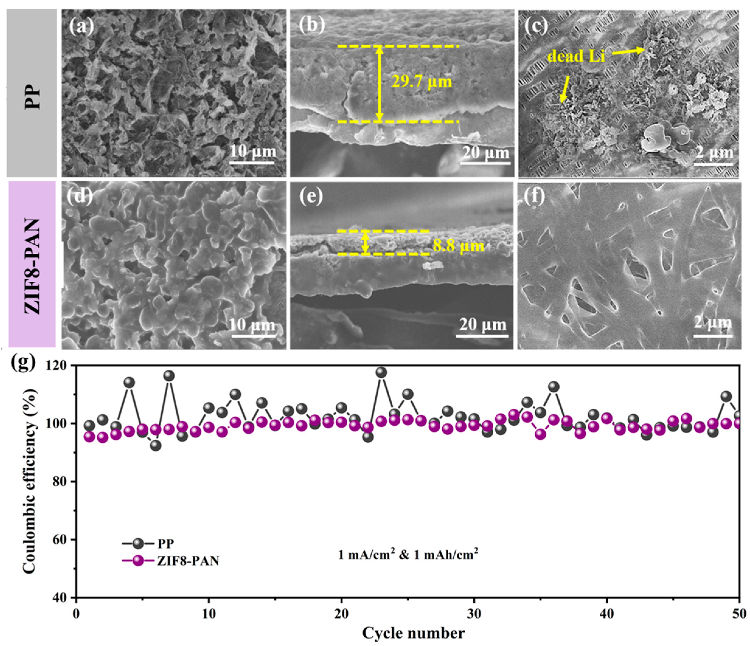
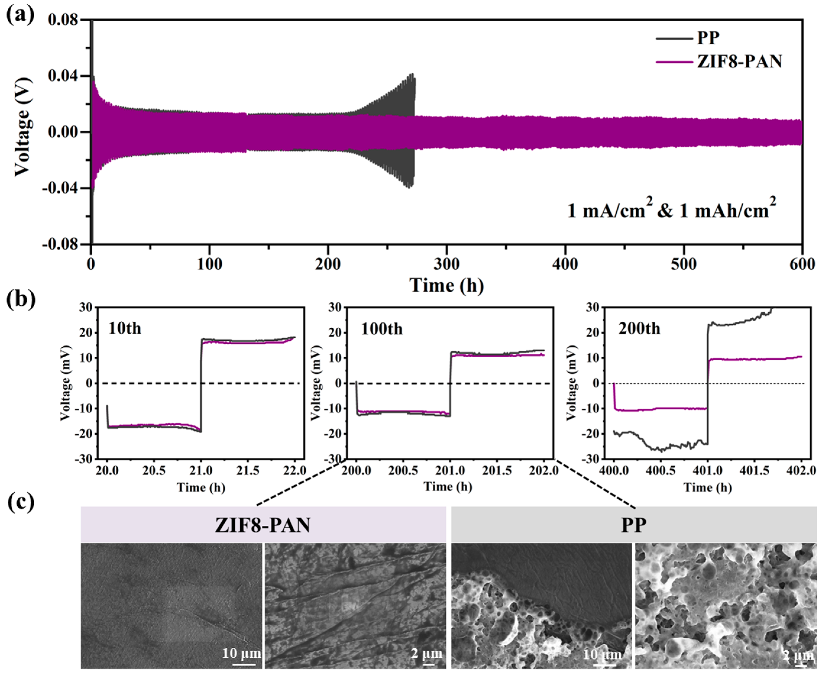
3.5. Stability of ZIF8-PAN Separator with Li Anode

To explore the impact of the ZIF8-PAN separator on the electrochemical performances of the Li anode, Li//Cu half cells applying different separators were cycled under a current density of 0.5 mA/cm2, with an area deposition capacity of 1 mAh/cm2. After 50 cycles, the Li deposition on the Cu foils were characterized by SEM to gain an in-depth understanding of the impact of the distinct separators on the Li deposition behaviors. For the battery using the traditional PP separator, as shown in Figure 5a, the metallic Li deposited on the Cu foil tended to be one-dimensional disordered growth and evolved into dendrites. Combined with the cross-sectional morphology (Figure 5b), it can be found that the Li deposition layer was powdered and fluffy, with a thickness of 29.7 μm. In fact, the capacity of 1 mAh/cm2 is nearly equivalent to Li foil of 5 μm. As a consequence, the uneven and porous Li deposition layer led to a large change in its volume. By contrast, when using the PAN and ZIF8-PAN separators (Figure S6a and Figure 5d), the deposited metallic Li was more compact and presented a cluster-like morphology; additionally, no obvious Li dendrites were observed, even under larger current densities and area capacities (Figure S7). In addition, the thickness of the plating layer was greatly reduced to 10.98 μm (Figure S6b) and 8.80 μm (Figure 5e), respectively, indicating that the 3D network structure of PAN and ZIF8-PAN have provided a homogenous Li+ flux, and evenly dispersed ZIF-8 nanoparticles could further enhance this effect. Meanwhile, the changes in the surface morphology of the different separators disassembled from the Li//Cu cells were also observed. For the PP separator (Figure 5c), a certain amount of inactive Li remained on its surface and in the channels, which would lead to different degrees of electrolyte penetration and aggravate the problem of uneven Li growth. For the PAN separator (Figure S6c), the pores in the network were not blocked, but the surface adhered with some “dead Li”, while the ZIF8-PAN separator could maintain the original morphology without obvious “dead Li” (Figure 5f), suggesting that the ZIF8-PAN separator helps to induce uniform Li deposition, decrease the generation of dead Li, and build a stable SEI layer.
The mechanism of the ZIF8-PAN separator in Li deposition was explored through a cyclic voltammetry (CV) test. As can be seen in Figure S8, for the battery using the PP separator, the reduction peak at a voltage of 1.0 V corresponds to the decomposition of electrolyte solute ion (TFSI) during the formation of SEI, and the wide peak at 0.3~0.4 V corresponds to the decomposition of the solvent molecules (DOL and DME). At the same time, the PAN and ZIF8-PAN separators also show a similar peak shape, but the decomposition voltage of TFSI is lower, indicating that the SEI layer formation in the battery is more difficult than that of the PP separator, which can provide extra time and space for the formation of SEI with improved uniformity and for the subsequent Li deposition process.
To denmonstrate Li utilization during the plating/stripping prosesses, the Coulombic efficiency (CE) of the Li//Cu half cells assembled with specific separators was tested under a current density of 1 mA/cm2 and area capacity of 1 mAh/cm2. The CE value is calculated from the ratio of the delithium capacity to the lithium plating capacity in each cycle. The results, exhibited in Figure S9, show that the PAN separator displays a drastic change in the CE, while in Figure 5g, the CE value of the PP separator is slightly unstable, but notably the ZIF8-PAN separator exhibits a higher and more stable CE, which maintained 96.7% over 50 cycles, indicating that the existence of ZIF-8 can effectively promote the dynamical process of Li plating/stripping and enhance the stability of the Li anode.
The long-term electrochemical stability and voltage polarization were explored via Li plating/stripping tests in Li//Li symmetric cells assembled with the PP, PAN, and ZIF8-PAN separators, respectively. All the symmetric cells were charged and discharged under a current density of 1 mA/cm2 with an area capacity of 1 mAh/cm2. As displayed in Figure 6a and Figure S10a, the PP-based and PAN-based cells exhibit large voltage hysteresis after cycling for 200 and 450 h, respectively. The undesirable voltage hysteresis shows a growing trend with the battery cycling, which would lead to a limited cycling lifespan. In contrast, the ZIF8-PAN-based symmetric battery shows a low voltage hysteresis of 30 mV for more than 600 h, demonstrating its stable Li plating/stripping behavior. Furthermore, to further emphasize the difference in the voltage polarization at certain cycles, the magnified voltage profiles of the symmetric cells with specific separators are shown in Figure 6b and Figure S10b. Furthermore, the SEM morphological characterization performed on the Li electrode after the 100th cycle in the Li//Li symmetric cells with the PP and ZIF8-PAN separator show that the Li electrode using ZIF8-PAN (Figure 6c) displays a dendrites-free surface. Overall, the ZIF8-PAN separator helps to enhance the dynamic characteristics and guide the homogeneous Li+ deposition, thereby promoting the stability of the consecutive Li plating/stripping [52].

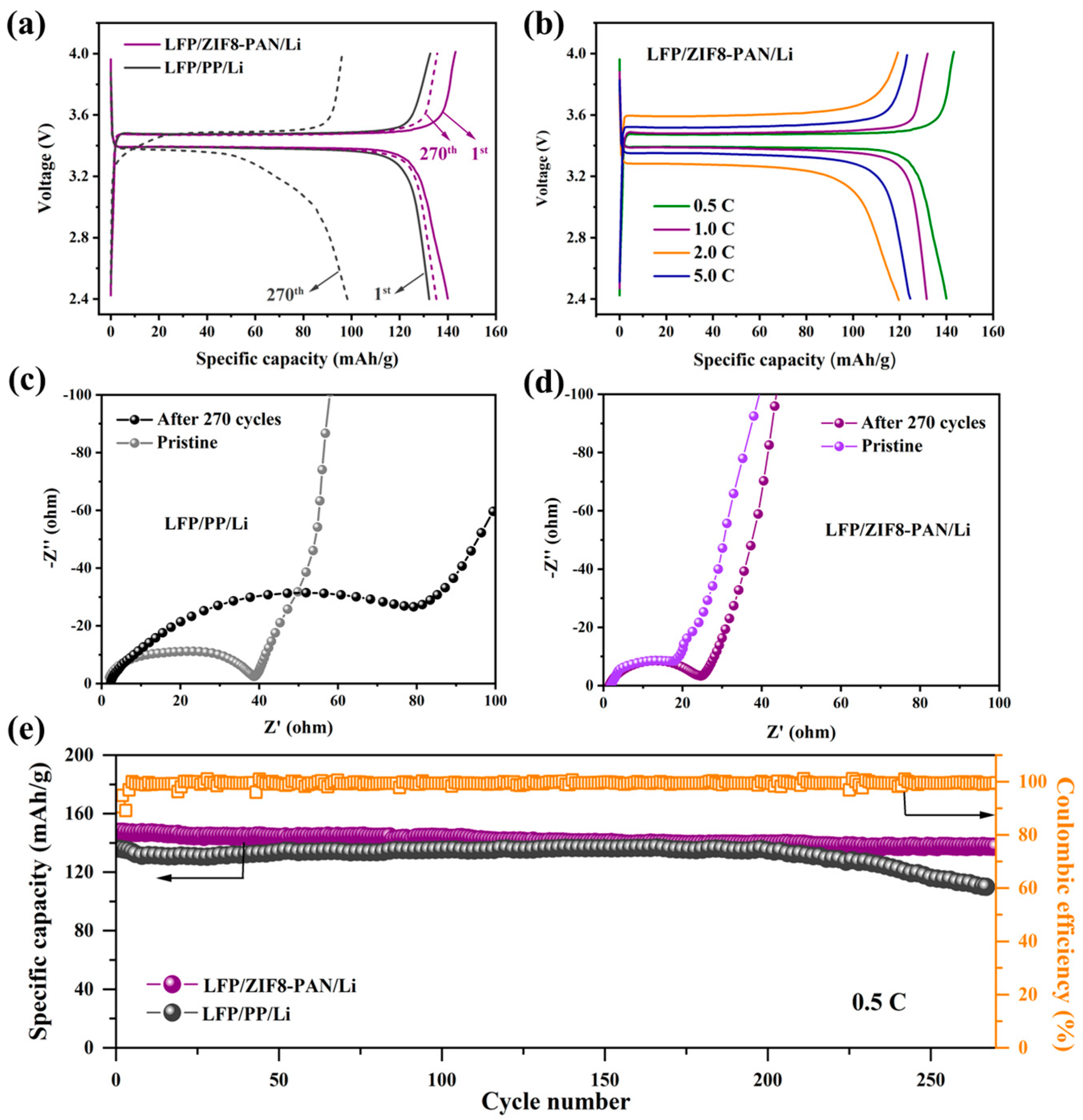
3.6. Cycling Performance of LFP/Separator/Li Cell

To further explore the commercialization capability of the ZIF8-PAN separator for the LMB, full cells were assembled via pairing with the LiFePO4 cathode. In the same way, the PP separator-based full cells were also prepared for analysis and comparison. The galvanostatic charge/discharge curves of the ZIF8-PAN-based and PP-based full cells are shown in Figure 7a (0.5 C), which display an initial discharge specific capacity of 140 and 132 mAh/g, respectively. Moreover, the charge-discharge curves of the ZIF8-PAN-based full cell at different current densities are shown in Figure 7b. Even under the current density of 5 C, a high reversible specific capacity of 120 mAh/g can be achieved. In order to better understand how the electrospun separator affects the battery impedance over cycling, the EIS measurements are displayed for the pristine Li//LiFePO4 full cells and for the cycled ones in Figure 7c,d. The cycling performance was evaluated by galvanostatic tests in the potential range of 2.8 to 4.2 V. As shown in Figure 7e, the ZIF8-PAN-based full cell could retain a discharge specific capacity of 142 mAh/g after 270 cycles at 0.5 C, and the CE value is more than 99.5%. However, the PP-based full cell is faced with a decline after 200 cycles, and the capacity is only 112 mAh/g after 270 cycles, which derives from the fact that the relatively poor stability of the Li anode has limited the normal development of the cathode material’s capacity. The cycling performance of the PAN-based full cell was also tested and is exhibited in Figure S11. Furthermore, SEM analyses were performed on the pristine and post-mortem LiFePO4 electrode, shown in Figure S12, which vividly points to the advantage of the ZIF8-PAN over the PP system.

4. Conclusions

The ZIF8-PAN composite separator was successfully fabricated via the electrospinning method to cover the shortcomings of the lower ionic conductivity, insufficient dendrite inhibition ability, and poor interface compatibility of the traditional separators. The 3D interconnected nano-network of the PAN fiber skeleton in the ZIF8-PAN separator can contribute to the uniform Li+ distribution and abundant channels for rapid Li+ transmission. Moreover, the ZIF-8 nanoparticles embedded in the PAN fiber could further regulate the uniform Li+ deposition to suppress the Li dendrites growth, and thus enhance the interface stability of the Li anode. These cooperative superiorities together determined the good electrochemical properties of the ZIF8-PAN composite separator. The obtained separator showed a wide electrochemical window (5.04 V), low voltage hysteresis (30 mV), and a significantly prolonged cycle life over 400 cycles in the Li//Li symmetric cells, and a high capacity of 142 mAh/g with a Coulombic efficiency of 99.5% over 270 cycles (0.5 C) in the Li//LiFePO4 full cells. With the ZIF8-PAN separator, the fabrication of stable-cycling Li metal batteries with excellent electrochemical performances can be expected. This work offers a feasible strategy for the separator preparation in dendrite-free Li metal batteries.

Supplementary Materials

The following supporting information can be downloaded at: https://www.mdpi.com/article/10.3390/batteries9030166/s1, Figure S1: The SEM images of ZIF-8 nanoparticles, PP and PAN separator under different magnification; Figure S2: XRD results of different separators; Table S1: The physical and eletrochemical properties of separators; Figure S3: Optical photographs after pouring electrolyte onto different separators; Figure S4: Tensile strength test of different separators; Figure S5: Chronoamperometry profiles and Nyquist plots for symmetric cells with PP and PAN separators; Figure S6: SEM images of PAN separator disassembled from Li/PAN/Cu half cells; Figure S7: SEM morphology of Li deposited with ZIF8-PAN separator at different current densities; Figure S8: Initial discharge CV curves of cells assembled with certain separators; Figure S9: CE of Li//Cu half cells with PAN separator; Figure S10: Cyclic stability of symmetric cells assembled with PAN and ZIF8-PAN separators; Figure S11: Cyclic performance of full cell assembled with PAN; Figure S12: SEM analysis of pristine and cycled LiFePO4 electrodes using PP and ZIF8-PAN separator.

Author Contributions

Conceptualization, T.L. and J.Q.; Formal analysis, Y.Z. and T.H.; Funding acquisition, T.L.; Investigation, T.L.; Methodology, J.Z.; Resources, J.Q.; Supervision, J.Z. and J.Q.; Validation, X.H., Y.Z. and T.H.; Writing—original draft, T.L.; Writing—review and editing, X.H., Y.Z., T.H., J.Z. and J.Q. All authors have read and agreed to the published version of the manuscript.

Funding

This research has been funded by the Key Research and Development Project of Gansu Natural Energy Research Institute (2021YF-01).

Data Availability Statement

The authors confirm that the data supporting the findings of this study are available within the article.

Acknowledgments

The authors appreciate the financial support of the Postdoctoral Research Foundation of Gansu Academy of Sciences and the Postdoctoral Research Project from Department of Human Resources and Social Security of Gansu Province (No. BSH2022-02; 302806), the Longyuan Youth Innovation and Entrepreneurship Talent Project from Organization Department of Gansu Provincial Party Committee, and the Talent Introduction Program of Gansu Natural Energy Research Institute. The authors acknowledge the material supply from Jiajia Chen’s group in Xiamen University.

Conflicts of Interest

The authors declare no conflict of interest.

References

  1. Cheng, X.B.; Zhang, R.; Zhao, C.Z.; Zhang, Q. Toward safe lithium metal anode in rechargeable batteries: A review. Chem. Rev. 2017, 117, 10403–10473. [Google Scholar] [CrossRef] [PubMed]
  2. Liu, J.; Bao, Z.; Cui, Y.; Dufek, E.J.; Goodenough, J.B.; Khalifah, P.; Li, Q.; Liaw, B.Y.; Liu, P.; Manthiram, A.; et al. Pathways for practical high-energy long-cycling lithium metal batteries. Nat. Energy 2019, 4, 180–186. [Google Scholar] [CrossRef] [Green Version]
  3. Wu, F.; Maier, J.; Yu, Y. Guidelines and trends for next-generation rechargeable lithium and lithium-ion batteries. Chem. Soc. Rev. 2020, 49, 1569–1614. [Google Scholar] [CrossRef] [PubMed]
  4. Sun, Y.; Liu, N.; Cui, Y. Promises and challenges of nanomaterials for lithium-based rechargeable batteries. Nat. Energy 2016, 1, 16071. [Google Scholar] [CrossRef]
  5. Xu, X.; Wang, S.; Wang, H.; Hu, C.; Jin, Y.; Liu, J.; Yan, H. Recent progresses in the suppression method based on the growth mechanism of lithium dendrite. J. Energy Chem. 2018, 27, 513–527. [Google Scholar] [CrossRef] [Green Version]
  6. Wang, P.; Qu, W.; Song, W.L.; Chen, H.; Chen, R.; Fang, D. Electro-chemo-mechanical issues at the interfaces in solid-state lithium metal batteries. Adv. Funct. Mater. 2019, 29, 1900950. [Google Scholar] [CrossRef]
  7. Xia, S.; Wu, X.; Zhang, Z.; Cui, Y.; Liu, W. Practical challenges and future perspectives of all-solid-state lithium-metal batteries. Chem 2019, 5, 753–785. [Google Scholar] [CrossRef]
  8. Gao, X.; Zhou, Y.N.; Han, D.; Zhou, J.; Zhou, D.; Tang, W.; Goodenough, J.B. Thermodynamic understanding of Li-dendrite formation. Joule 2020, 4, 1864–1879. [Google Scholar] [CrossRef]
  9. Guo, Q.; Deng, W.; Xia, S.J.; Zhang, Z.B.; Zhao, F.; Hu, B.J.; Zhang, S.S.; Zhou, X.F.; Chen, G.Z.; Liu, Z.P. Nano-channel-based physical and chemical synergic regulation for dendrite-free lithium plating. Nano Res. 2021, 14, 3585–3597. [Google Scholar] [CrossRef]
  10. Li, Y.N.; Wang, C.Y.; Gao, R.M.; Cao, F.F.; Ye, H. Recent smart lithium anode configurations for high-energy lithium metal batteries. Energy Storage Mater. 2021, 38, 262–275. [Google Scholar] [CrossRef]
  11. Yang, C.P.; Yin, Y.X.; Zhang, S.F.; Li, N.W.; Guo, Y.G. Accommodating lithium into 3D current collectors with a submicron skeleton towards long-life lithium metal anodes. Nat. Commun. 2015, 6, 8058. [Google Scholar] [CrossRef] [PubMed] [Green Version]
  12. Park, S.; Jin, H.J.; Yun, Y.S. Advances in the design of 3D-structured electrode materials for lithium-metal anodes. Adv. Mater. 2020, 32, 2002193. [Google Scholar] [CrossRef] [PubMed]
  13. Li, C.; Liu, S.; Shi, C.; Liang, G.; Lu, Z.; Fu, R.; Wu, D. Two-dimensional molecular brush-functionalized porous bilayer composite separators toward ultrastable high-current density lithium metal anodes. Nat. Commun. 2019, 10, 1363. [Google Scholar] [CrossRef] [Green Version]
  14. Lu, Q.; He, Y.; Yu, Q.; Li, B.; Kaneti, Y.V.; Yao, Y.; Kang, F.; Yang, Q.H. Dendrite-free, high-rate, long-life lithium metal batteries with a 3D cross-linked network polymer electrolyte. Adv. Mater. 2017, 29, 1604460. [Google Scholar] [CrossRef]
  15. Huang, J.D.; Liu, J.D.; He, J.; Wu, M.G.; Qi, S.H.; Wang, H.P.; Li, F.; Ma, J.M. Optimizing electrode/electrolyte interphases and Li-ion flux/solvation for lithium-metal batteries with qua-functional heptafluorobutyric anhydride. Angew. Chem. Int. Ed. 2021, 60, 20717–20722. [Google Scholar] [CrossRef]
  16. Han, Y.; Liu, B.; Xiao, Z.; Zhang, W.; Wang, X.; Pan, G.; Xia, Y.; Xia, X.; Tu, J. Interface issues of lithium metal anode for high-energy batteries: Challenges, strategies, and perspectives. InfoMat 2021, 3, 155–174. [Google Scholar] [CrossRef]
  17. Wang, Z.; Wang, Y.; Zhang, Z.; Chen, X.; Lie, W.; He, Y.B.; Zhou, Z.; Xia, G.; Guo, Z. Building artificial solid-electrolyte interphase with uniform intermolecular ionic bonds toward dendrite-free lithium metal anodes. Adv. Funct. Mater. 2020, 30, 2002414. [Google Scholar] [CrossRef]
  18. Yang, H.; Guo, C.; Naveed, A.; Lei, J.; Yang, J.; Nuli, Y.; Wang, J. Recent progress and perspective on lithium metal anode protection. Energy Storage Mater. 2018, 14, 199–221. [Google Scholar] [CrossRef]
  19. Huang, X. Separator technologies for lithium-ion batteries. J. Solid State Electrochem. 2011, 15, 649–662. [Google Scholar] [CrossRef]
  20. Deimede, V.; Elmasides, C. Separators for lithium-ion batteries: A review on the production processes and recent developments. Energy Technol. 2015, 3, 453–468. [Google Scholar] [CrossRef]
  21. Zhao, H.; Deng, N.; Kang, W.; Li, Z.; Wang, G.; Cheng, B. Highly multiscale structural Poly (vinylidene fluoridehexafluoropropylene)/poly-m-phenyleneisophthalamide separator with enhanced interface compatibility and uniform lithium-ion flux distribution for dendrite-proof lithium-metal batteries. Energy Storage Mater. 2020, 26, 334–348. [Google Scholar] [CrossRef]
  22. Lu, X.; Bertei, A.; Finegan, D.P.; Tan, C.; Daemi, S.R.; Weaving, J.S.; O’Regan, K.B.; Heenan, T.M.M.; Hinds, G.; Emma Kendrick, E.; et al. 3D microstructure design of lithium-ion battery electrodes assisted by X-ray nano-computed tomography and modelling. Nat. Commun. 2020, 11, 2079. [Google Scholar] [CrossRef] [PubMed]
  23. Li, X.; Yuan, L.; Liu, D.; Liao, M.; Chen, J.; Yuan, K.; Xiang, J.; Li, Z.; Huang, Y. Elevated Lithium Ion Regulation by a “Natural Silk” Modified Separator for High-Performance Lithium Metal Anode. Adv. Funct. Mater. 2021, 31, 2100537. [Google Scholar] [CrossRef]
  24. Zhang, S.S. A review on the separators of liquid electrolyte Li-ion batteries. J. Power Sources 2007, 164, 351–364. [Google Scholar] [CrossRef]
  25. Lee, H.; Yanilmaz, M.; Toprakci, O.; Fu, K.; Zhang, X. A review of recent developments in membrane separators for rechargeable lithium-ion batteries. Energy Environ. Sci. 2014, 7, 3857–3886. [Google Scholar] [CrossRef]
  26. Arora, P.; Zhang, Z. Battery separators. Chem. Rev. 2004, 104, 4419–4462. [Google Scholar] [CrossRef]
  27. Yang, C.; Jia, Z.; Guan, Z.; Wang, L. Polyvinylidene fluoride membrane by novel electrospinning system for separator of Li-ion batteries. J. Power Sources 2009, 189, 716–720. [Google Scholar] [CrossRef]
  28. Zeng, F.; Xu, R.; Ye, L.; Xiong, B.; Kang, J.; Xiang, M.; Li, L.; Sheng, X.; Hao, Z. Effects of heat setting on the morphology and performance of polypropylene separator for lithium ion batteries. Ind. Eng. Chem. Res. 2019, 58, 2217–2224. [Google Scholar] [CrossRef]
  29. Ryu, J.; Han, D.Y.; Hong, D.; Park, S. A polymeric separator membrane with chemoresistance and high Li-ion flux for high-energy-density lithium metal batteries. Energy Storage Mater. 2022, 45, 941–951. [Google Scholar] [CrossRef]
  30. Shen, L.; Wu, H.B.; Liu, F.; Zhang, C.; Ma, S.; Le, Z.; Lu, Y. Anchoring anions with metal-organic framework-functionalized separators for advanced lithium batteries. Nanoscale Horiz. 2019, 4, 705–711. [Google Scholar] [CrossRef]
  31. Luo, J.; Li, Y.; Zhang, H.; Wang, A.; Lo, W.S.; Dong, Q.; Wong, N.; Povinelli, C.; Shao, Y.; Chereddy, S.; et al. A metal-organic framework thin film for selective Mg2+ transport. Angew. Chem. Int. Ed. 2019, 58, 15313–15317. [Google Scholar] [CrossRef]
  32. Zhuang, T.Z.; Huang, J.Q.; Peng, H.J.; He, L.Y.; Cheng, X.B.; Chen, C.M.; Zhang, Q. Rational integration of polypropylene/graphene oxide/nafion as ternary-layered separator to retard the shuttle of polysulfides for lithium-sulfur batteries. Small 2016, 12, 381–389. [Google Scholar] [CrossRef] [PubMed]
  33. Gao, K.; Hu, X.; Dai, C.; Yi, T. Crystal structures of electrospun PVDF membranes and its separator application for rechargeable lithium metal cells. Mater. Sci. Eng. B 2006, 131, 100–105. [Google Scholar] [CrossRef]
  34. Hu, M.; Ma, Q.; Yuan, Y.; Pan, Y.; Chen, M.; Zhang, Y.; Long, D. Grafting polyethyleneimine on electrospun nanofiber separator to stabilize lithium metal anode for lithium sulfur batteries. Chem. Eng. J. 2020, 388, 124258. [Google Scholar] [CrossRef]
  35. Chen, C.; Zhang, W.; Zhu, H.; Li, B.G.; Lu, Y.; Zhu, S. Fabrication of metal-organic framework-based nanofibrous separator via one-pot electrospinning strategy. Nano Res. 2021, 14, 1465–1470. [Google Scholar] [CrossRef]
  36. Ryou, M.H.; Lee, Y.M.; Park, J.K.; Choi, J.W. Mussel-inspired polydopamine-treated polyethylene separators for high-power Li-ion batteries. Adv. Mater. 2011, 23, 3066–3070. [Google Scholar] [CrossRef]
  37. Qin, J.; Shi, H.; Huang, K.; Lu, P.; Wen, P.; Xing, F.; Yang, B.; Ye, M.; Yu, Y.; Wu, Z.S. Achieving stable Na metal cycling via polydopamine/multilayer graphene coating of a polypropylene separator. Nat. Commun. 2021, 12, 5786. [Google Scholar] [CrossRef]
  38. Kim, J.K.; Kim, D.H.; Joo, S.H.; Choi, B.; Cha, A.; Kim, K.M.; Kwon, T.H.; Kwak, S.K.; Kang, S.J.; Jin, J. Hierarchical chitin fibers with aligned nanofibrillar architectures: A nonwoven-mat separator for lithium metal batteries. ACS Nano 2017, 11, 6114–6121. [Google Scholar] [CrossRef]
  39. Cheng, D.; Yang, X.; He, Z.; Ni, Y. Potential of cellulose-based materials for lithium-ion batteries (LIB) separator membranes. J. Bioresour. Bioprod. 2016, 1, 18–21. [Google Scholar]
  40. Baghali, M.; Jayathilaka, W.A.D.M.; Ramakrishna, S. The role of electrospun nanomaterials in the future of energy and environment. Materials 2021, 14, 558. [Google Scholar] [CrossRef]
  41. Wang, G.; He, P.; Fan, L.Z. Asymmetric Polymer Electrolyte Constructed by Metal–Organic Framework for Solid-State, Dendrite-Free Lithium Metal Battery. Adv. Func. Mater. 2021, 31, 2007198. [Google Scholar] [CrossRef]
  42. Hao, Z.; Wu, Y.; Zhao, Q.; Tang, J.; Zhang, Q.; Ke, X.; Liu, J.; Jin, Y.; Wang, H. Functional Separators Regulating Ion Transport Enabled by Metal-Organic Frameworks for Dendrite-Free Lithium Metal Anodes. Adv. Funct. Mater. 2021, 31, 2102938. [Google Scholar] [CrossRef]
  43. Fu, Q.; Zhang, W.; Muhammad, I.P.; Chen, X.; Zeng, Y.; Wang, B.; Zhang, S. Coaxially electrospun PAN/HCNFs@ PVDF/UiO-66 composite separator with high strength and thermal stability for lithium-ion battery. Micropor. Mesopor. Mater. 2021, 311, 110724. [Google Scholar] [CrossRef]
  44. Cho, T.H.; Tanaka, M.; Onishi, H.; Kondo, Y.; Nakamura, T.; Yamazaki, H.; Tanase, S.; Sakai, T. Battery performances and thermal stability of polyacrylonitrile nano-fiber-based nonwoven separators for Li-ion battery. J. Power Sources 2008, 181, 155–160. [Google Scholar] [CrossRef]
  45. Liu, J.; Liu, Y.; Yang, W.; Ren, Q.; Li, F.; Huang, Z. Lithium ion battery separator with high performance and high safety enabled by tri-layered SiO2@ PI/m-PE/SiO2@ PI nanofiber composite membrane. J. Power Sources 2018, 396, 265–275. [Google Scholar] [CrossRef]
  46. Liu, X.; Song, K.; Lu, C.; Huang, Y.; Duan, X.; Li, S.; Ding, Y. Electrospun PU@ GO separators for advanced lithium ion batteries. J. Membr. Sci. 2018, 555, 1–6. [Google Scholar] [CrossRef]
  47. Liang, Y.; Cheng, S.; Zhao, J.; Zhang, C.; Sun, S.; Zhou, N.; Qiu, Y.; Zhang, X. Heat treatment of electrospun Polyvinylidene fluoride fibrous membrane separators for rechargeable lithium-ion batteries. J. Power Sources 2013, 240, 204–211. [Google Scholar] [CrossRef]
  48. Gong, W.Z.; Gu, J.F.; Ruan, S.L.; Shen, C.Y. A high-strength electrospun PPESK fibrous membrane for lithium-ion battery separator. Polym. Bull. 2019, 76, 5451–5462. [Google Scholar] [CrossRef]
  49. Huang, D.; Liang, C.; Chen, L.; Tang, M.; Zheng, Z.; Wang, Z. MOF composite fibrous separators for high-rate lithium-ion batteries. J. Mater. Sci. 2021, 56, 5868–5877. [Google Scholar] [CrossRef]
  50. He, Y.; Chang, Z.; Wu, S.; Qiao, Y.; Bai, S.; Jiang, K.; He, P.; Zhou, H. Simultaneously Inhibiting Lithium Dendrites Growth and Polysulfides Shuttle by a Flexible MOF-Based Membrane in Li-S Batteries. Adv. Energy. Mater. 2018, 8, 1802130. [Google Scholar] [CrossRef]
  51. Yang, L.Y.; Cao, J.H.; Cai, B.R.; Liang, T.; Wu, D.Y. Electrospun MOF/PAN composite separator with superior electrochemical performances for high energy density lithium batteries. Electrochim. Acta 2021, 382, 138346. [Google Scholar] [CrossRef]
  52. Hao, Z.; Zhao, Q.; Tang, J.; Zhang, Q.; Liu, J.; Jin, Y.; Wang, H. Functional separators towards the suppression of lithium dendrites for rechargeable high-energy batteries. Mater. Horiz. 2021, 8, 12–32. [Google Scholar] [CrossRef] [PubMed]
Figure 1. Schematic diagram of: (a) non-uniform deposition of Li ions after passing through PP separator; (b) uniform deposition of Li ions after redistribution through the obtained ZIF8-PAN separator.
Batteries 09 00166 g001
Figure 2. (a) Fabrication diagram and optical photograph of ZIF8-PAN separator. The SEM images of ZIF8-PAN composite membrane before hot-pressing: (b) top-view, (e) cross-section; after hot-pressing: (c,d) top-view; (f) cross-section. (g) TEM image of ZIF8-PAN separator. (h) EDS element mapping distribution of ZIF8-PAN separator.
Batteries 09 00166 g002
Figure 3. The results of (a) TGA; (b) DTG measurement of ZIF-8 powder and three kinds of separators. The comparison of (c,d) heat shrinkage tests; (e) electrolyte contact angle of PP, PAN and ZIF8-PAN separators.
Batteries 09 00166 g003
Figure 4. Electrochemical characterization of the cells assembled with three different separators at 25 °C. (a) Electrochemical impedance spectra for SS//SS cells. (b) LSV of SS//Li cells. (c) Chronoamperometry profile and (d) Nyquist plot before and after polarization for symmetric battery assembled with ZIF8-PAN separator.
Batteries 09 00166 g004
Figure 5. SEM images of (a,d) top-surface of Cu foil; (b,e) cross-section of Cu foil; (c,f) the surface of the separators disassembled from Li//Cu half cells with PP and ZIF8-PAN separator, respectively. (g) The CE comparison of Li//Cu half cells with PP and ZIF8-PAN separator for a current density of 1.0 mA/cm2 with an area capacity of 1.0 mAh/cm2.
Batteries 09 00166 g005
Figure 6. (a) The cycling stability of the Li//Li symmetric cells assembled with PP and PAN separators under current density of 1.0 mA/cm2 with area capacity of 1.0 mAh/cm2 at 25 °C. (b) Corresponding magnified voltage profiles at the 10th, 100th and 200th cycle. (c) The SEM analysis of 100th cycled Li electrodes tested in Li//Li symmetric cells using certain separator.
Batteries 09 00166 g006
Figure 7. The electrochemical performances of Li//LiFePO4 full cells assembled with PP and ZIF8-PAN separators. (a) Voltage profiles for the first and 270th cycle at 0.5 C. (b) Charge/discharge performance of ZIF8-PAN-based full cells under different current densities. (c,d) EIS results of pristine and cycled full cells. (e) Cyclic performance of two types of cells at 0.5 C.
Batteries 09 00166 g007
Disclaimer/Publisher’s Note: The statements, opinions and data contained in all publications are solely those of the individual author(s) and contributor(s) and not of MDPI and/or the editor(s). MDPI and/or the editor(s) disclaim responsibility for any injury to people or property resulting from any ideas, methods, instructions or products referred to in the content.

