
Magnetoelectric Coupling Effects in Tb-Doped BiFeO3 Nanoparticles


1
Faculty of Forest Industry, University of Forestry, Kl. Ohridsky Blvd. 10, 1756 Sofia, Bulgaria
2
Faculty of Hydrotechnics, Civil Engineering and Geodesy, University of Architecture, Hristo Smirnenski Blvd. 1, 1046 Sofia, Bulgaria
3
Faculty of Physics, Sofia University “St. Kliment Ohridski”, J. Bouchier Blvd. 5, 1164 Sofia, Bulgaria
*
Author to whom correspondence should be addressed.
Magnetochemistry 2023, 9(6), 142; https://doi.org/10.3390/magnetochemistry9060142
Submission received: 18 April 2023
/
Revised: 16 May 2023
/
Accepted: 24 May 2023
/
Published: 26 May 2023
(This article belongs to the Special Issue Advances in Magnetic Nanomaterials and Nanostructures)
Abstract
:The magnetic, electric, and optical properties in Tb-doped BiFeO3 nanoparticles as functions of size and doping concentrations were investigated using a microscopic model, taking into account both linear and quadratic magnetoelectric (ME) coupling. We observed improved multiferroic properties and band-gap tuning. The magnetization and polarization increased with the decreased nanoparticle size and increased Tb-doping substitution x. The Neel temperature remained nearly unchanged whereas the Curie temperature was reduced with the increased x. There was doping-induced ME coupling. The dielectric constant is discussed as a function of the size, doping, and the magnetic field. The band gap decreased with the decreased size or increased Tb dopants due to competing effects of the compressive strain, oxygen defects on the surface, and Coulomb interactions. Increasing the Tb dopants and decreasing the nanoparticle size improved the ME effect.
1. Introduction
Multiferroics are materials that exhibit the coexistence of at least two of the electric, elastic, and magnetic orders within a single phase [1,2]. They are of interest for memory and logic device applications because the coupling between ferroelectric and magnetic properties enables a dynamical interaction between the corresponding order parameters. As proposed by Khomskii, there are two types of multiferroics: type-I and type-II [3]. Type-I multiferroics are often good ferroelectrics. The critical temperatures of the magnetic and ferroelectric transitions can be well above room temperature, where the ferroelectric one is much larger than the ferromagnetic one. The ME coupling between the order parameters—magnetization and polarization—is quadratic and is usually rather weak. The mechanism that can lead to ferroelectricity can be charge ordering or the displacement of ions or ion groups, often observed in transition metal compounds, for example, hexagonal RMnO3 [4]. Type-II multiferroic materials are materials in which the magnetic ordering breaks the inversion symmetry and directly “causes” the ferroelectricity. In these so-called “spin driven ferroelectrics”, the non-collinear spin spiral structure is responsible for the inversion symmetry breaking. In magnetically driven multiferroics, the macroscopic electric polarization is induced by the long-range magnetic order, which is non-centrosymmetric. Examples of such oxides are orthorhombic RMnO3 [5]. The ferroelectric and magnetic phase transition temperatures are nearly the same and the ME coupling is usually linear and very strong.
The linear magnetoelectric (ME) effect was theoretically and experimentally observed for the first time in Cr2O3 in the 1960s [6,7]. In the following years, the search for single-phase ME compounds with larger linear ME values has attracted much attention [8], which is important for potential applications. One of the most studied multiferroic (MF) materials is BiFeO3 (BFO). Bulk BFO shows a small quadratic ME coupling due to the large difference between the ferroelectric Curie temperature ( = 1103 K) and the Neel temperature ( = 643 K) [9]. Recently, some experimental works were published, showing that in ion-doped BFO, the ME effects improved; there also appears to be a stronger linear ME effect, which, theoretically, has not been intensively studied.
The multiferroic behavior of BFO can be influenced by the size and doping with different ions. In low-dimensional BFO, the magnetic structure changes and becomes collinear, adopting the G-type. The magnetic anisotropy constant grows, which is the reason for the destruction of the spiral structure. The structure of rhombohedral becomes monoclinic. Structural studies have shown that significant changes in the crystal lattice constant occur at the surface. The changes in the structural parameters and the symmetry point group of the crystal drastically change the physical characteristics of the low-size BFO. Magnetic measurements in BFO nanoparticles [10,11,12,13,14,15] show an increase in magnetization and a decrease in the value of the coercive field with a decrease in the BFO nanoparticle size. This behavior is a consequence of surface-induced magnetization.
With ion doping, strains appear, which, due to the different ionic radii between the doping and host ions, can change the lattice parameters, the bond lengths, the interactions, and the properties of the compounds. The effect of Tb substitution on different properties of BFO has been investigated experimentally in [16,17,18,19]. The results provide evidence that the Tb-doped BFO shows an improvement in the multiferroic properties. Bulk BFO exhibits antiferromagnetic behavior, whereas pure and Tb-doped BFO nanoparticles (NPs) display ferromagnetic behavior [10,11,20,21,22]. The dielectric constant and loss are improved with Tb doping and the NP size [10]. Tb doping in BFO leads to structural transitions, as shown by Lotey et al. [21] and Xing et al. [11] through a crystallographic analysis and by Dong et al. [23] through a Raman spectroscopy study. The distorted deformation of the FeO6 octahedra in Tb-doped BFO (x = 0.10) gives rise to the enhanced ferroelectric and ferromagnetic properties. X-ray diffraction results of Chen et al. [22] reveal that the structure transition is around x = 0.11 in the Tb-doped BFO system. Moreover, Lotey et al. [21] reported the existence of longitudinal and transverse magnetoelectric (ME) coefficients. There is an explanation for the observed ME effect, which reaches its maximum at x = 0.5. The saturation polarization in Tb-doped BFO thin films is enhanced, as shown by Wang et al. [24] and Yi et al. [25].
Zhai et al. [26] have shown that Tb-doped BFO films exhibit higher ferromagnetism and a smaller optical band gap compared to pure BFO film. Bielecki et al. [27] and Muneeswaran et al. [17] observed a reduced band gap () with an increasing Tb concentration in BFO through UV-Vis diffuse reflectance spectra. We should emphasize that the decreasing is also observed by the doping of BFO with other rare-earth ions, for example Ho, Er, or Y [28,29,30]. However, Mukherjee et al. [31] surprisingly found that the of BFO NPs increases with an increasing Y ion doping.
The aim of the present paper is to investigate the effect of Tb substitution on the Bi site in BFO NPs on the MF and optical properties using a microscopic model, taking into account both the quadratic and linear ME effects. It must be noted that there are many theoretical works that consider the doping effects on different properties of BFO, but to date, to our knowledge, there is no theoretical study on the above problem regarding Tb ion doping.
2. The Model
BFO crystallizes in a distorted rhombohedral perovskite structure with a spatial symmetry group R3c, which allows, under , a simultaneous occurrence of ferroelectric atomic shifts and weak ferromagnetism appearances. The magnetic structure is of the G-type, composed of Fe magnetic ions, with each Fe3+ ion being surrounded by six Fe3+ nearest neighbors with antiparallel spins [32]. MF Tb-doped BFO, BiTbFeO, is described by the Hamiltonian:
The magnetic part is given by the Heisenberg model:
, where and are the components of the spin operator at the lattice site i; g is the gyromagnetic factor, and is the Bohr magneton. The exchange integrals and represent the couplings between the nearest and next-nearest-neighbor Fe ions, respectively; represents the single-ion anisotropy of the Fe ion, represents an external magnetic field. The fifth term describes the concentration x dependence by doping with Tb ions.
The studies have shown that the polarization is essentially due to the relative offsets of Bi-ions from the center of the FeO octahedra [33], i.e., BFO is a ferroelectric material of the displacive type. This means that, from a theoretical point of view, the ferroelectric properties of the system can be described on the basis of the pseudo-spin formalism within the transverse Ising model [34]:
where and are the spin-1/2 operators of the pseudo-spins. The pseudo-spin operator determines the two positions of the ferroelectric unit. The transverse term with the flipping rate and the operator gives the dynamics of the ferroelectric part. denotes the exchange pseudo-spin interaction constant. x denotes the Tb ion-doping concentration.
From the said above, it follows that the structural units responsible for the occurrence of polarization and magnetization are different. From a theoretical and symmetrical point of view, this means that the relationship between the two order parameters must be quadratic along the spins and the pseudo-spin operators. The bulk BFO shows a small quadratic ME coupling [35], but the Tb-doped BFO exhibits also a stronger linear ME. Let us emphasize that Tb ion doping enhances the ME coupling constant, which is larger in Tb-doped NPs compared to Tb-doped bulk compounds. There is a doping-induced ME coupling. The argument for this assumption is the fact that the rare-earth ion replaces Bi, which, when shifting to Fe, determines the appearance of spontaneous polarization in the direction [1;1;1]. On the other hand, the Tb ion is magnetic and realizes an isotropic exchange interaction with the Fe spins; this interaction is modulated by polar lattice shifts caused by the difference in the ionic radii of Bi and Tb ions. This static shift leads to the appearance of an additional polarization , where is the Born charge, which is a consequence of the spin correlation between rare-earth ions and Fe. Thus, the second term in Equation (4) can be formally viewed as the so-called Peierls spin–phonon interaction. Therefore, we consider both quadratic and linear ME couplings between the order parameters, i.e., polarization and magnetization:
where and are the quadratic and linear ME coupling constants, respectively.
Although many theoretical and experimental research studies have been conducted on the coupling between magnetic and electric subsystems, the form of ME energy and the coupling mechanism are still important issues for debate. As for the ME effect induced by an applied field, it has been pointed out by Alcantara and Gehring [36] that, on the basis of thermodynamics, symmetry, and spin configurations provided by ME experiments, an allowed, possible term exists in the system free energy, where E and H represent electric and magnetic fields, respectively. Wu et al. [37] proposed a possible form based on the Heisenberg model for inherent ME coupling. Katsufuji and Takagi [38] found that the changes in the dielectric and magnetic properties of the hexagonal ferroelectromagnet RMnO are dominated by the pair correlation of the nearest-neighbor Mn ion spins, . Thus, for the coupling between the intrinsic spin and polarization, there are sufficient reasons for proposing such a biquadratic magnetoelectric coupling term, Equation (4), e.g., to theoretically study the magnetic and dielectric properties in pure BFO.
Let us emphasize that, for pure BFO, due to the large difference between the temperatures of the ferroelectric and magnetic phase transitions (), BFO is defined as a multiferroic of type I, in which different structural units of the elementary cell are responsible for the occurrence of magnetic ordering and ferroelectricity in one (and the same) phase. For symmetric reasons, for such compounds, the magnetoelectric coupling must be quadratic with respect to the two ordering parameters. After ion doping shifts to the Neel temperature, and for a given doping concentration, the two phase-transition temperatures are nearly equal, which is characteristic of multiferroics of type II, where the magnetoelectric constant is linear between the two order parameters. Thus, the second term in Equation (4) is 0 for x = 0, and then with an increasing x, the contribution of this term increases, and for a given concentration (in our calculations, this is x = 0.1) would be larger compared to the quadratic one.
The magnetization M for the arbitrary spin value S is calculated from the Green’s function (where = 1 for , it is 0 for , is the thermodynamic average value, [,] means commutator or anti-commutator):
is the spin wave energy.
The excitation energy in the generalized Hartree–Fock approximation is observed using the method by Tserkovnikov [39]:
From the Green’s function, , the polarization P is calculated as follows:
is the pseudo-spin excitation energy.
In order to calculate the band-gap energy of the materials, the s-d model is used [40]. To the modified Heisenberg model , the following terms are added: for the conduction band electrons
is the hopping integral, v is the Coulomb interaction, , are Fermi-creation and -annihilation operators; and the s-d coupling term
I is the s-d interaction, represents the spin operators of the conduction electrons: , , .
The band-gap energy of BFO is observed from the difference between the valence and conduction bands:
The dielectric function is calculated from the equation:
where Z is the electron charge and V is the volume. In order to obtain , we have to calculate the Green’s function .
3. Numerical Results and Discussion
The BFO NP has a spherical cuboctahedral shape. The Fe spins are situated into shells, , where is the central spin and is the surface shell. The morphological study by Lotey et al. [21] confirms the spherical symmetry of the synthesized BFO NPs.
The exchange interaction depends on the distance between the spins and is inversely proportional to the lattice parameters. The surface effects are taken into account by different coupling parameters within the surface layer compared to the bulk ones . So the properties are discussed on a microscopic level.
The following model parameters are used for the numerical calculations: = 55 K, = −115 K [41], = 47.2 K [42], = 0.01 K, = 0.2 K, = −1.2 K, = 235 K, = 20 K, = 15 K [21], I = 0.2 eV, v = 0.3 eV, S = 3 for the magnetic spins, and S = 0.5 for the pseudo-spins. The exchange interaction between the Tb ions could be neglected. The model parameters for the ferroelectric subsystem and are calculated from the following expressions: , , below , and ≈ with 40–45 K (the energies of the ferroelectric system assumed within our model) at very high temperatures [34]. The values for the s-d model I and v are taken from reference [40].
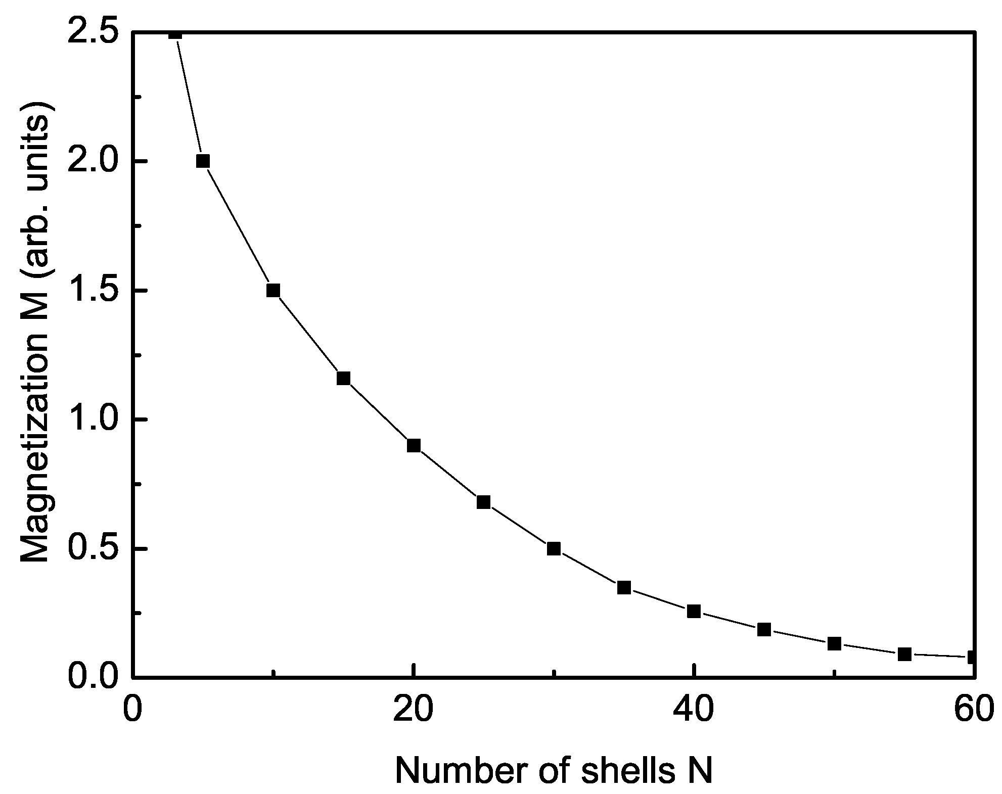
First, the magnetization M of a pure BFO NP is considered, taking into account the relation . Bulk BFO is antiferromagnetic, but due to surface effects, weak ferromagnetism in the BFO NPs [43] appears. Thus, M increases with the decreasing NP size, i.e., M is size-dependent (see Figure 1, curve 1). Similar behavior of M in BFO nanostructures was reported in [10,11,19]. The polarization P also increases with the decreasing NP size (not shown here).
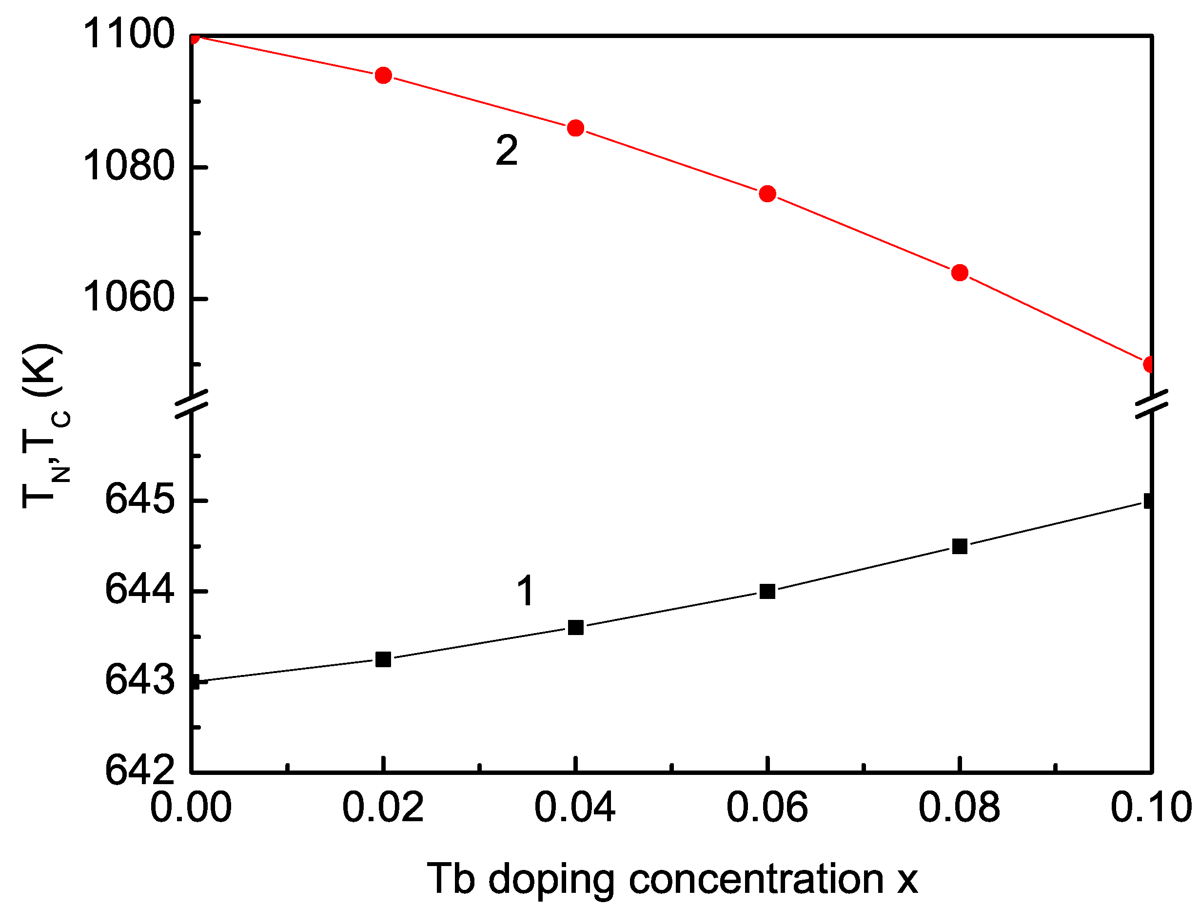
BFO crystallizes with rhombohedral symmetry at room temperature. Doping of Tb in BFO results in an orthorhombic structural transformation [44]. The radius of the Tb ion (1.06 ) is smaller than that of the Bi ion (1.365 ), i.e., in the doped BFO NP, and appears as a compressive strain. We have to choose the relation between the exchange interaction in the doped state and that in the undoped one , because depends on the lattice parameters, on the distance between the spins. The magnetization M increases with the increasing Tb dopants (see Figure 2, curve 1). This enhancement of M is due to the phase transformations from rhombohedral to orthorhombic with a breakdown of the spin cycloidal structure, the spin canting, and the uncompensated spin on the surface, i.e., due to both doping and nanoscale effects in Tb-doped BFO NPs. The crystal structure and magnetism of BFO NPs can be regulated by rare-earth Tb substitution on the Bi site. An increase of M in Tb-doped BFO NPs was reported in [11,19,45]. The Neel temperature remains nearly the same; it increases very slightly, from 643 to 645 K (see Figure 3, curve 1).
The importance of the linear ME coupling in a Tb-doped BFO NP is shown in Figure 2, curve 2a. The increasing x also raises the contribution from the linear ME term. It must be noted that for = const, we observe a very small increase in the polarization P or the magnetization M. In order to achieve the significant increase in P or M reported in some experimental studies, we have to use a linear ME coupling constant that is dependent on x, and is fitted from experimental data. In the inset of Figure 2, the dependence of the ME coupling on the doping concentration x for h = 0 and T = 300 K is presented. As x increases, the contribution of the second term of the linear ME coupling increases; the value of also increases, reaching saturation, which is in agreement with the experimental data by Reddy et al. [46]. The obtained results can be explained qualitatively as follows: Changing the length and angle of the connections between the main magnetic ions leads to the destabilization of the spiral structure and the appearance of weak ferromagnetism and/or an increase in macroscopic magnetization. This is a consequence of the large magnetic moments of RE ions. They are in the paramagnetic state and oriented in the direction of the weak ferromagnetism. This will lead to an increase in as x increases, i.e., an increase in magnetization at a constant value of the magnetic field and, therefore, an increase in the second term with the linear ME coupling constant . For small values of x, the growth of is the greatest; because in this interval, the structural phase transition from rhombohedral to orthorhombic crystal lattices takes place, in which there is a collapse of the incommensurable spiral structure and the appearance and growth of weak ferromagnetism (the appearance of macroscopic magnetization). Further ion doping will not lead to a significant increase in the ME coefficient because the saturation of the magnetization is reached (Figure 2, curve 1). As x increases, the influence of the contribution of the term increases, inducing additional magnetization in the doped system. We can conclude that in order to explain the experimental data, both ME couplings, and must be taken into account.
The polarization P also increases with the increasing Tb dopants (see Figure 2, curve 2). This dependence can qualitatively be explained as follows: The highly anisotropic magnetic Tb ion creates an internal local magnetic field, which is in the direction of spontaneous polarization P, and leads to an increase in the pseudo-spin interaction . As the x concentration of the magnetic Tb ions increases, this internal magnetic field increases, and will increase. This means that at a fixed temperature, spontaneous polarization P will increase, i.e., with the increase in the Tb concentration x, the ferroelectric phase will be stabilized. Similar behavior was observed by Yao et al. [18] and Wang et al. [24]. Thus, we have shown that a small Tb substitution of BFO NPs improves their MF properties. Therefore, Tb-doped BFO is a potential candidate for ME device applications. The ferroelectric phase transition temperature decreases as Tb dopants increase, from 1100 to 1050 K for x = 0–0.1 (see Figure 3, curve 2). Let us emphasize that spin wave and pseudo-spin wave energies are depending on x through the and dependencies. and are observed as temperatures for which M or P vanish. Therefore, they also depend on x, which is in agreement with the experimental data. All quantities are calculated self-consistently.
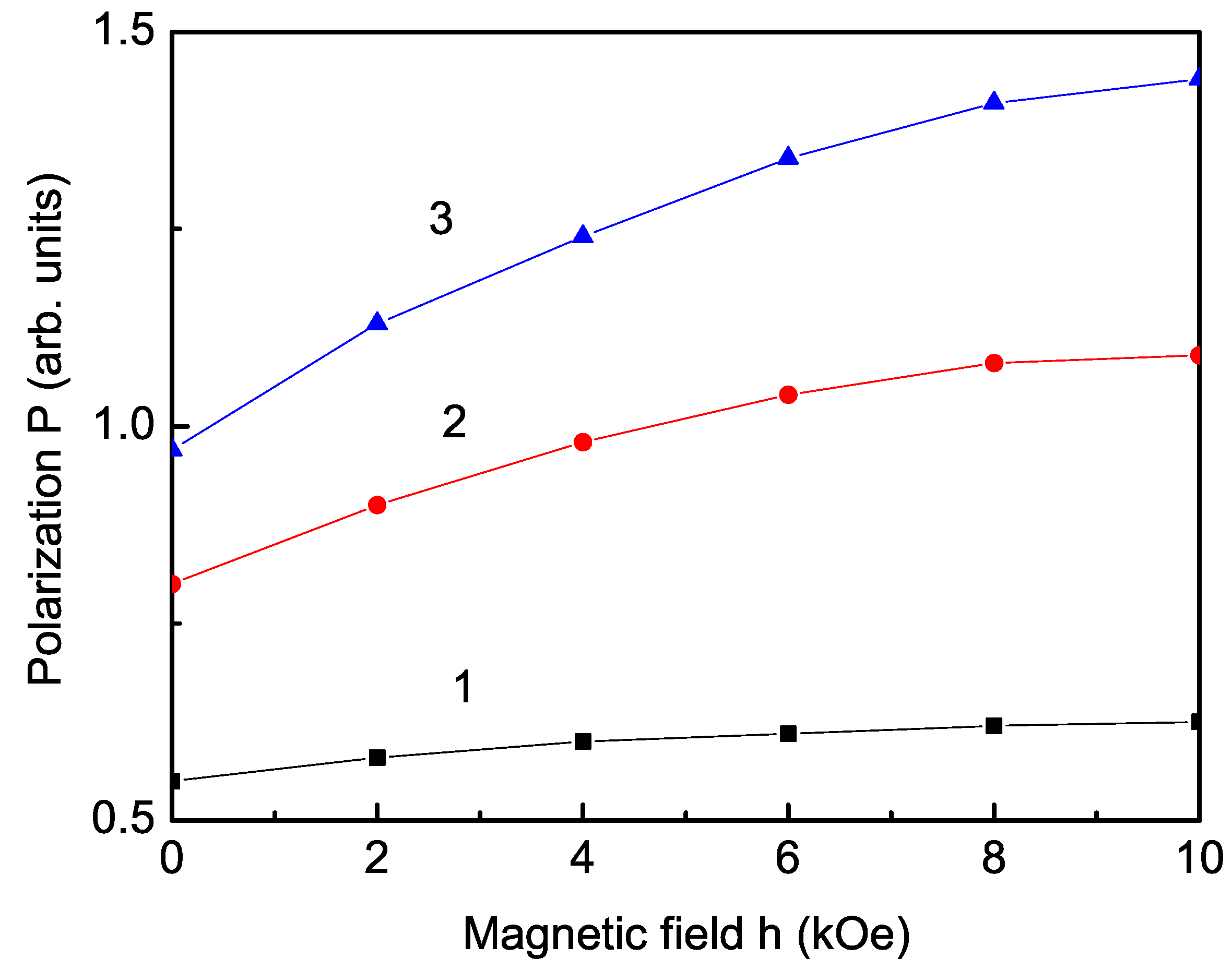
From the magnetic field dependence of the polarization P (see Figure 4), we can see that P increases as h increases at room temperature. This is evidence for the MF behavior of Tb-doped BFO NPs. Moreover, the polarization P increases more strongly for larger Tb dopants. Figure 4 clearly reveals that the polarization increases with the increase in the applied magnetic field h for all samples. This is due to the larger ME coupling in Tb-doped BFO NP compared to the undoped case; the considered linear coupling term is considered in addition to the quadratic one in Equation (4). The increase of the ME coupling in BFO nano-films doped with other rare-earth ions, for example, La and Nd, is observed by Guo et al. [47].
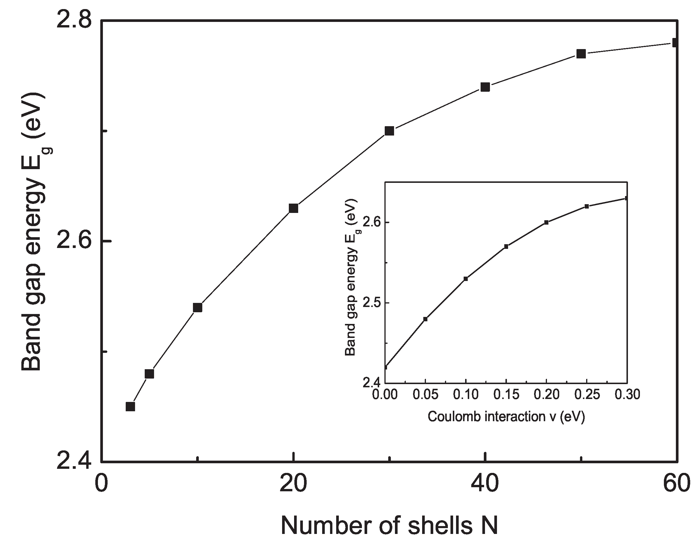
Bulk undoped BFO has a relatively large band gap, which is reported to be 2.7–2.8 eV [48,49]. We calculated the band-gap energy from Equation (11) as a function of size for a pure BFO using the relation between the surface and bulk exchange interaction values , . The result is shown in Figure 5. It can be seen that decreases as the NP size decreases, which is due to the competing effects of the compressive strain, oxygen defects on the surface, and Coulomb interactions. Our results are in good qualitative coincidence with the experimental data by Mocherla et al. [50] and Sharma et al. [51].
The inset in Figure 5 presents the effect of the Coulomb interaction v on the band-gap energy for a BFO NP with N = 20 N. decreases as v decreases, i.e., in order to explain the experimental values of BFO bulk and NPs, the Coulomb interaction v must be taken into account; otherwise, we would have very little value for the band gap .
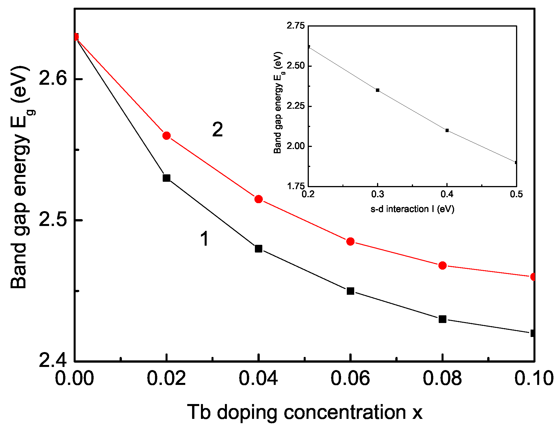
Next, we will calculate the band-gap energy of a Tb-doped BFO NP. Figure 6 demonstrates the dependence of the band-gap energy on the Tb-doping concentration x. It can be seen that decreases as x increases, i.e., the band gap decreases as the lattice parameters decrease by the appeared compressive strain in the Tb-doped BFO NP. Moreover, this behavior may be due to the distortion induced in the Fe-O octahedron. The band gap reduction in Tb-doped BFO NPs is possible due to lattice contractions, resulting from reducing the Fe-O and Fe-O-Fe bond lengths. Thus, decreasing the Fe-O bond length while substituting Tb into the BFO structure may considerably increase the electron bandwidth W and reduce the band-gap energy . It can be seen from Figure 6 that as the Tb concentration increases, the dopant impact on the band-gap value seems to reduce, and it tends to a limit. It must be noted that increasing the s-d interaction I decreases the band-gap energy (see inset in Figure 6). This reduction means that the Tb-doped BFO NP has enhanced photocatalytic properties because of its reduced band-gap energy. Moreover, this decrease of can be useful for optoelectronic applications. Our results regarding the band-gap energy in a Tb-doped BFO NP are in good qualitative agreement with the experimental data reported in references [17,26,27,30].
A similar reduced with the increasing doping ion concentration is also reported for other rare-earth-doping ions, such as Ho, Y, Er, Sm, Gd, La, Eu, Dy, etc. [28,29,30,51,52,53,54,55]; Mukherjee et al. [31] observed that the band gap of BFO NPs increases with the increasing Y ion dopants.
Let us emphasize that for a smaller value of (for example 20 K) (see Figure 6, curve 2), the decrease of with x is smaller compared to the case with = 30 K (curve 1).
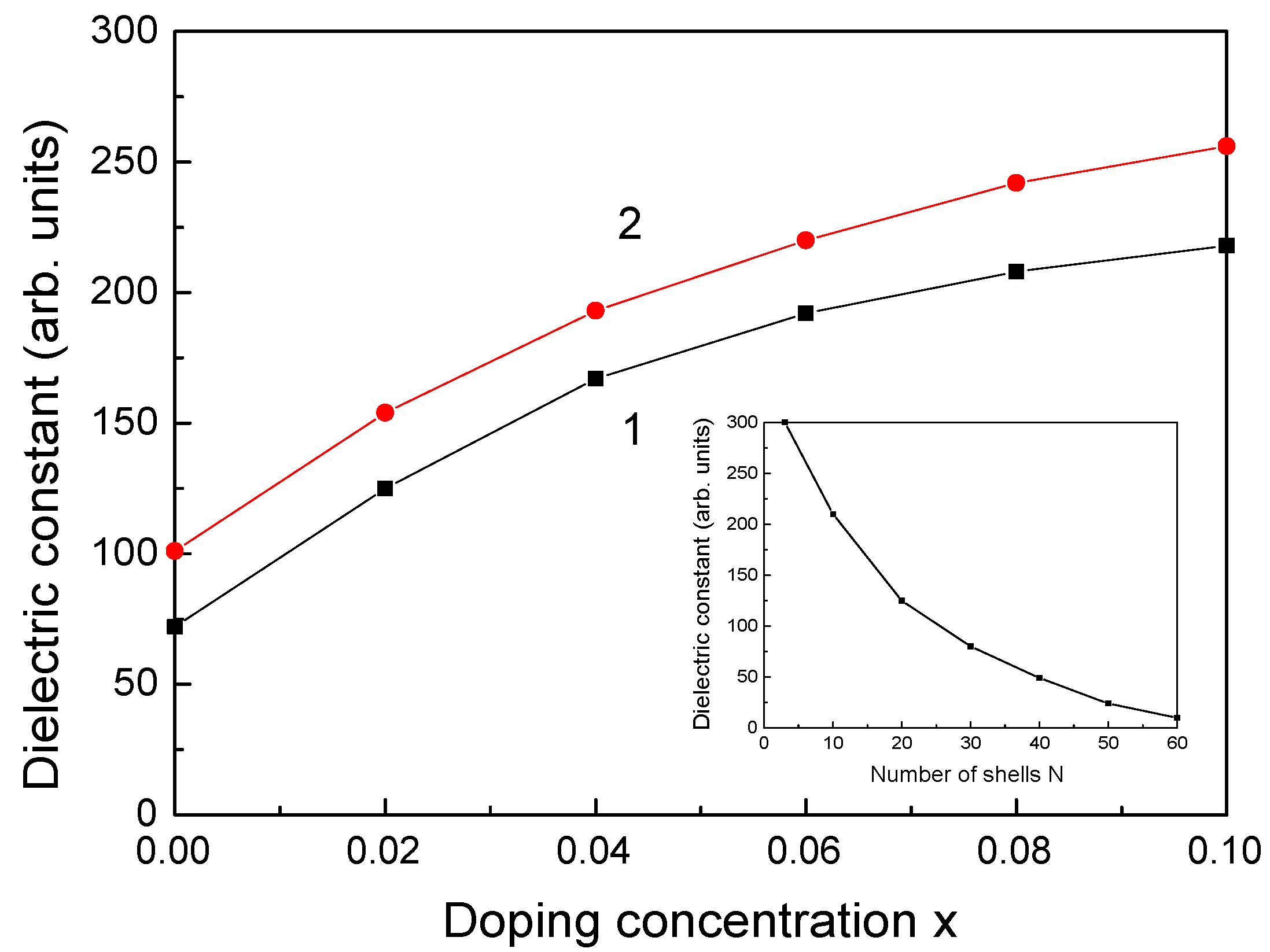
To our knowledge, the dielectric behaviors of Tb-doped BFO NPs have not been intensively investigated. Therefore, for the first time, we will study the effects of size, magnetic field, and doping on the dielectric constant of BFO NPs using Equation (10). We observe that the real part of the dielectric constant increases (see Figure 7, curve 1) whereas the imaginary part decreases (not shown here) with the increasing Tb-doping concentration x. It is observed that increases with the increasing magnetic field h (see Figure 7, curve 2), which is evidence for the strong magnetodielectric behavior. Moreover, is enhanced with the decreasing BFO NP size (see inset in Figure 7). Dhir et al. [10] have experimentally observed an enhancement of with Tb doping and the decreasing NP size. A similar increase of the dielectric constant was reported for Sm- and Gd-doped BFO NPs by Singh et al. [56] and Sm-doped BFO thin films by Golda et al. [57].
4. Conclusions
We conclude that the observed results are a result of the combined effects of doping and nanoscale effects. There is a strong relationship between structural, magnetic, electric, and optical properties in pure and Tb-doped BFO NPs. Substituting Tb ions on the Bi site induces weak ferromagnetism, and due to the ME coupling, it also changes the long-range ferroelectric order. Tb can affect the magnetic structure due to the interaction with the Fe spins and the lattice distortion caused by the ionic radii difference of the host atom and dopant. is nearly the same, whereas decreases as Tb dopants increase. The magnetization M, the polarization P, and the dielectric constant increase whereas the band-gap energy decreases as the NP size decreases, or as the Tb ion-doping concentration increases due to the competing effects of the compressive strain by the substitution of Tb on the Bi site, the oxygen defects on the surface, and the Coulomb interaction v. Remarkably enhanced linear ME coupling is observed in the doped NPs.
Author Contributions
Conceptualization, J.W.; Methodology, I.A.; Software, I.A.; Validation, J.W.; Formal analysis, A.A.; Investigation, A.A.; Writing—original draft, A.A.; Supervision, J.W. All authors contributed equally to this work. All authors have read and agreed to the published version of the manuscript.
Funding
This research received no external funding.
Institutional Review Board Statement
Not applicable.
Informed Consent Statement
Not applicable.
Data Availability Statement
Derived data supporting the findings of this study are available from the corresponding author upon reasonable request.
Acknowledgments
A.T.A. acknowledges financial support from the Center for Research and Design at the University of Architecture, Civil Engineering, and Geodesy, in Sofia (contract number BN-289/23).
Conflicts of Interest
The authors declare no conflict of interest.
References
- Fiebig, M.; Lottermoser, T.; Meier, D.; Trassin, M. The evolution of multiferroics. Nat. Rev. Mater. 2016, 1, 16046. [Google Scholar] [CrossRef]
- Spaldin, N.A.; Ramesh, R. Advances in magnetoelectric multiferroics. Nat. Mater. 2019, 18, 203–212. [Google Scholar] [CrossRef] [PubMed]
- Khomskii, D.I. Multiferroics: Different ways to combine magnetism and ferroelectricity. J. Magn. Magn. Mater. 2006, 306, 1–8. [Google Scholar] [CrossRef]
- Lorenz, B. Hexagonal Manganites-(RMnO3): Class (I) Multiferroics with Strong Coupling of Magnetism and Ferroelectricity. ISRN Cond. Matter Phys. 2013, 2013, 497073. [Google Scholar] [CrossRef]
- Single-Phase Type-II Multiferroics: Frustrated Magnetism-Triggered Ferroelectricity. In Book Multiferroic Materials; Wang, J. (Ed.) CRC Press: Boca Raton, FL, USA, 2016. [Google Scholar]
- Dzyaloshinskii, I.E. On the magneto-electrical effects in antiferromagnets. Sov. Phys. JETP 1960, 10, 628–629. [Google Scholar]
- Astrov, D.N. The magnetoelectric effect in antiferromagnetics. Sov. Phys. JETP 1960, 11, 708–709. [Google Scholar]
- Ramesh, R.; Spaldin, N.A. Multiferroics: Progress and prospects in thin films. Nat. Mater. 2007, 6, 21–29. [Google Scholar] [CrossRef]
- Puhan, A.; Bhushan, B.; Nayak, A.K.; Rout, D. Fundamentals and Properties of Multifunctional Nanomaterials; Thomas, S., Kalarikkal, N., Abraham, A.R., Eds.; Elsevier: Amsterdam, The Netherlands, 2021; Chapter 12; pp. 275–293. [Google Scholar]
- Dhir, G.; Lotey, G.S.; Uniyal, P.; Verma, N.K. Size-dependent magnetic and dielectric properties of Tb-doped BiFeO3 nanoparticles. J. Mater. Sci. Mater. Electr. 2013, 24, 4386. [Google Scholar] [CrossRef]
- Xing, Q.X.; Han, Z.; Zhao, S. Crystal structure and magnetism of BiFeO3 nanoparticles regulated by rare-earth Tb substitution. J. Mater. Sci. Mater. Electr. 2017, 28, 295. [Google Scholar] [CrossRef]
- Mazumder, R.; Ghosh, S.; Mondal, P.; Bhattacharya, D.; Dasgupta, S.; Das, D.; Sen, A.; Tyagi, A.K.; Sivakumar, M.; Takami, J.; et al. Particle size dependence of magnetization and phase transition near TN in multiferroic BiFeO3. J. Appl. Phys. 2006, 100, 033908. [Google Scholar] [CrossRef]
- Mazumder, R.; Devi, P.S.; Bhattacharya, D.; Choudhury, P.; Sen, A.; Raja, M. Ferromagnetism in nanoscale BiFeO3. Appl. Phys. Lett. 2007, 91, 062510. [Google Scholar] [CrossRef]
- Tae-Jin Park, T.-J.; Papaefthymiou, G.C.; Viescas, A.J.; Moodenbaugh, A.R.; Wong, S.S. Size-Dependent Magnetic Properties of Single-Crystalline Multiferroic BiFeO3 Nanoparticles. Nano Lett. 2007, 7, 766–772. [Google Scholar] [CrossRef]
- Chattopadhyay, S.; Kelly, S.D.; Palkar, V.R.; Fan, L.; Segre, C.U. Investigation of size effects in magnetoelectric BiFeO3. Phys. Scripta. 2005, 2005, 709. [Google Scholar] [CrossRef]
- Yang, C.-H.; Kan, D.; Takeuchi, I.; Nagaraj, V.; Seidel, J. Doping BiFeO3: Approaches and enhanced functionality. Phys. Chem. Chem. Phys. 2012, 14, 15953. [Google Scholar] [CrossRef]
- Muneeswaran, M.; Dhanalakshmi, R.; Giridharan, N. Effect of Tb substitution on structural, optical, electrical and magnetic properties of BiFeO3. J. Mater. Sci. Mater. Electr. 2015, 26, 3827. [Google Scholar] [CrossRef]
- Yao, Y.; Liu, W.; Chan, Y.; Leung, C.; Mak, C.; Ploss, B. Studies of Rare-Earth-Doped BiFeO3 Ceramics. Int. J. Appl. Ceram. Techn. 2011, 8, 1246. [Google Scholar] [CrossRef]
- Gervits, N.E.; Tkachev, A.V.; Zhurenko, S.V.; Gunbin, A.V.; Gippius, A.A.; Makarova, A.O.; Pokatilov, V.S. Emergence of collinear magnetic structure in Tb-doped BiFeO3. J. Magn. Magn. Mater. 2011, 563, 170031. [Google Scholar] [CrossRef]
- Dhir, G.; Uniyal, P.; Verma, N.K. Effect of partice size on the MF properties of Tb-doped BiFeO3 nanoparticles. J. Supercond. Nov. Magn. 2016, 29, 2621. [Google Scholar] [CrossRef]
- Lotey, G.S.; Verma, N.K. Magnetoelectric coupling in multiferroic Tb-doped BiFeO3. Mater. Lett. 2013, 111, 55. [Google Scholar] [CrossRef]
- Chen, X.; Hu, G.; Wu, W.; Yang, C.; Wang, X.; Fan, S. Large Piezoelectric Coefficient in Tb-Doped BiFeO3 Films. J. Am. Ceram. Soc. 2010, 93, 948. [Google Scholar] [CrossRef]
- Dong, G.; Tan, G.; Luo, Y.; Liu, W.; Ren, H.; Xia, A. Investigation of Tb-doping on structural transition and multiferroic properties of BiFeO3 thin films. Ceram. Int. 2014, 40, 6413. [Google Scholar] [CrossRef]
- Wang, Y.; Nan, C.-W. Effect of Tb doping on electric and magnetic behavior of BiFeO3 thin films. J. Appl. Phys. 2008, 103, 024103. [Google Scholar] [CrossRef]
- Yi, M.L.; Wang, C.B.; Li, L.; Wang, J.M.; Shen, Q.; Zhang, L.M. Influence of Tb doping on structure and multiferroic properties of BiFeO3 films prepared by pulsed laser deposition. Appl. Surf. Sci. 2015, 344, 47–51. [Google Scholar] [CrossRef]
- Zhai, X.; Deng, H.; Yang, P.; Chu, J. Effect of Tb-doping on structural, magnetic and optical properties of BiFeO3 films prepared by chemical solution deposition. Mater. Lett. 2015, 158, 266. [Google Scholar] [CrossRef]
- Bielecki, J.; Svedlindh, P.; Tibebu, D.T.; Cai, S.; Eriksson, S.-G.; Borjesson, L.; Knee, C.S. Structural and Magnetic Properties of Isovalently Substituted Multiferroic BiFeO3: Insights From Raman Spectroscopy. Phys. Rev. B 2012, 86, 184422. [Google Scholar] [CrossRef]
- Nayek, C.; Al-Akhras, M.; Obaidat, I. Tuning of the optical band-gap of rare earth doped BiFeO3 submicron particles for solar cell applications. In Proceedings of the 2018 5th International Conference on Renewable Energy: Generation and Applications (ICREGA), Al Ain, United Arab Emirates, 25–28 February 2018. [Google Scholar]
- Li, Z.; Cheng, L.; Zhang, K.; Wang, Z. Enhanced photocatalytic performance by Y-doped BiFeO3 particles derived from MOFs precursor based on band gap reduction and oxygen vacancies. Appl. Organomech. Chem. 2021, 35, e6113. [Google Scholar]
- Haruna, A.; Abdulkadir, I.; Idris, S.O. Photocatalytic activity and doping effects of BiFeO3 nanoparticles in model organic dyes. Heliyon 2020, 6, e03237. [Google Scholar] [CrossRef] [PubMed]
- Mukherjee, A.; Hossain, S.M.; Pal, M.; Basu, S. Effect of Y-doping on optical properties of multiferroics BiFeO3 nanoparticles. Appl. Nanosci. 2012, 2, 305. [Google Scholar] [CrossRef]
- Sosnowska, I.; Peterlin-Neumaier, T.; Steichele, E. Spiral magnetic ordering in bismuth ferrite. J. Phys. C 1982, 15, 4835. [Google Scholar] [CrossRef]
- Wang, N.; Luo, X.; Han, L.; Zhang, Z.; Zhang, R.; Olin, H.; Yang, Y. Structure, Performance, and Application of BiFeO3 Nanomaterials. Nano-Micro Lett. 2020, 12, 81. [Google Scholar] [CrossRef] [PubMed]
- Blinc, R.; Zeks, B. Soft Modes in Ferroelectrics and Antferroelectrics; North-Holland: Amsterdam, The Netherlands, 1974. [Google Scholar]
- Kovachev, S.; Wesselinowa, J.M. Electric field control of phonon properties in multiferroic BiFeO3 and hexagonal RMnO3. Solid State Commun. 2009, 149, 859–861. [Google Scholar] [CrossRef]
- Bonfim, O.F.A.; Gehring, G.A. Magnetoelectric effect in antiferromagnetic crystals. Adv. Phys. 1980, 29, 731. [Google Scholar] [CrossRef]
- Wu, H.; Jiang, Q.; Shen, W.Z. A possible coupling mechanism between magnetism and dielectric properties in EuTiO3 within the framework of the transverse-field Ising model. Phys. Lett. A 2004, 330, 358–364. [Google Scholar] [CrossRef]
- Katsufuji, T.; Mori, S.; Masaki, M.; Moritomo, Y.; Yamamoto, N.; Takagi, H. Dielectric and magnetic anomalies and spin frustration in hexagonal RMnO3 (R = Y, Yb, and Lu). Phys. Rev. B 2001, 64, 104419. [Google Scholar] [CrossRef]
- Tserkovnikov, Y.A. Decoupling of chains of equations for two-time Green’s functions. Theor. Math. Phys. 1971, 7, 511. [Google Scholar] [CrossRef]
- Nagayev, E.I. Spin Polaron Theory for Magnetic Semiconductors with Narrow Bands. Phys. Stat. Sol. B 1974, 65, 11. [Google Scholar] [CrossRef]
- Apostolov, A.T.; Apostolova, I.N.; Wesselinowa, J.M. Magnetic field effect on the dielectric properties of rare earth doped multiferroic BiFeO3. J. Magn. Magn. Mater. 2020, 513, 167101. [Google Scholar] [CrossRef]
- Mangin, S.; Montaigne, F.; Bellouard, C.; Fritzsche, H. Study of magnetic configurations in exchange-coupled bilayers by polarized neutron reflectometry. Appl. Phys. A 2002, 74, S631. [Google Scholar] [CrossRef]
- Wesselinowa, J.M. Size and anisotropy effects on magnetic properties of antiferromagnetic nanoparticles. J. Magn. Magn. Mater. 2010, 322, 234. [Google Scholar] [CrossRef]
- Lotey, G.S.; Verma, N.K. Multiferroic properties of Tb-doped BiFeO3 nanowires. J. Nanopart. Res. 2013, 15, 1553. [Google Scholar] [CrossRef]
- Puhan, A.; Bhushan, B.; Meena, S.S.; Nayak, A.K.; Rout, D. Surface engineered Tb and Co co-doped BiFeO3 nanoparticles for enhanced photocatalytic and magnetic properties. J. Mater. Sci. Mater. Electr. 2021, 32, 7956. [Google Scholar] [CrossRef]
- Reddy, V.A.; Pathak, N.P.; Nath, R. Enhanced magnetoelectric coupling in transition-metal-doped BiFeO3 thin films. Solid State Commun. 2013, 171, 40–45. [Google Scholar]
- Guo, K.; Zhang, R.; He, T.; Kong, H.; Deng, C. Multiferroic and in-plane magnetoelectric coupling properties of BiFeO3 nano-films with substitution of rare earth ions La3+ and Nd3+. J. Rare Earths 2016, 34, 1228–1234. [Google Scholar] [CrossRef]
- Qiao, L.; Zhang, S.; Xiao, H.Y.; Singh, D.J.; Zhang, K.H.L.; Liu, Z.J.; Zua, X.T.; Lic, S. Orbital controlled band gap engineering of tetragonal BiFeO3 for optoelectronic application. J. Mater. Chem. C 2018, 6, 1239. [Google Scholar] [CrossRef]
- Clark, S.J.; Robertson, J. Band gap and Schottky barrier heights of multiferroic BiFeO3. Appl. Phys. Lett. 2007, 90, 132903. [Google Scholar] [CrossRef]
- Mocherla, P.; Karthik, C.; Ubic, R.; Rao, M.S.R.; Sudakar, C. Tunable bandgap in BiFeO3 nanoparticles: The role of microstrain and oxygen defects. Appl. Phys. Lett. 2013, 103, 022910. [Google Scholar] [CrossRef]
- Sharma, S.; Kumar, M. Band gap tuning and optical properties of BiFeO3 nanoparticles. Mater. Today Proc. 2020, 28, 168. [Google Scholar] [CrossRef]
- Micard, Q.; Margueron, S.; Bartasyte, A.; Condorelli, G.G.; Malandrino, G. Dy-Doped BiFeO3 thin films: Piezoelectric and bandgap tuning. Mater. Adv. 2022, 3, 3446. [Google Scholar] [CrossRef]
- Irfan, S.; Shen, Y.; Rizwan, S.; Wang, H.; Khan, S.B.; Nan, C.W. Band-Gap Engineering and Enhanced Photocatalytic Activity of Sm and Mn Doped BiFeO3 Nanoparticles. J. Am. Ceram. Soc. 2017, 100, 31. [Google Scholar] [CrossRef]
- Hasan, M.; Basith, M.A.; Zubair, M.A.; Hossain, M.S.; Mahbub, R.; Hakim, M.A.; Islam, M.F. Saturation magnetization and band gap tuning in BiFeO3 nanoparticles via co-substitution of Gd and Mn. J. Alloys Compd. 2016, 687, 701. [Google Scholar] [CrossRef]
- Wrzesinska, A.; Khort, A.; Bobowska, I.; Busiakiewicz, A.; Wypych-Puszkarz, A. Influence of the La3+, Eu3+, and Er3+ Doping on Structural, Optical, and Electrical Properties of BiFeO3 Nanoparticles Synthesized by Microwave-Assisted Solution Combustion Method. J. Nanomater. 2019, 2019, 5394325. [Google Scholar] [CrossRef]
- Singh, E.C.; Singh, H.H.; Sharma, H.B. Effect of Rare Earth Elements Doping On Dielectric and Magnetic Properties of BiFeO3 Nanoparticles. AIP Conf. Proc. 2020, 2265, 030140. [Google Scholar]
- Golda, R.A.; Marikani, A.; Alex, E.J. Enhancement of dielectric, ferromagnetic and electrochemical properties of BiFeO3 nanostructured films through rare earth metal doping. Ceram. Int. 2020, 46, 1962–1973. [Google Scholar] [CrossRef]
Figure 1.
Size dependence of the magnetization M of a pure BFO NP for , and T = 300 K.

Figure 2.
(Color online.) Dependence of the magnetization M (curve 1) and polarization P (curve 2) on the Tb-doping concentration x in the Tb-doped BFO NP for N = 20 shells, , , , , T = 300 K for different values: (1) 30 K, (2) 30 K; (2a) 20 K. Inset: ME coupling constant .
Figure 2.
(Color online.) Dependence of the magnetization M (curve 1) and polarization P (curve 2) on the Tb-doping concentration x in the Tb-doped BFO NP for N = 20 shells, , , , , T = 300 K for different values: (1) 30 K, (2) 30 K; (2a) 20 K. Inset: ME coupling constant .

Figure 3.
(Color online.) Dependence of the Neel and Curie temperatures, (curve 1), and (curve 2), on the Tb-doping concentration x in the Tb-doped BFO NP for N = 20 shells, , , , .
Figure 3.
(Color online.) Dependence of the Neel and Curie temperatures, (curve 1), and (curve 2), on the Tb-doping concentration x in the Tb-doped BFO NP for N = 20 shells, , , , .

Figure 4.
(Color online). Dependence of the polarization P on the magnetic field h in Tb-doped BFO NP for different Tb-doping concentrations x: (1) 0; (2) 0.04; (3) 0.1; and N = 20 shells, , , , , T = 300 K.
Figure 4.
(Color online). Dependence of the polarization P on the magnetic field h in Tb-doped BFO NP for different Tb-doping concentrations x: (1) 0; (2) 0.04; (3) 0.1; and N = 20 shells, , , , , T = 300 K.

Figure 5.
Size dependence of the band-gap energy of pure BFO for , , and T = 300 K. Inset: for N = 20.
Figure 5.
Size dependence of the band-gap energy of pure BFO for , , and T = 300 K. Inset: for N = 20.

Figure 6.
(Color online). Dependence of the band-gap energy on the Tb-doping concentration x in Tb-doped BFO NP for N = 20 shells, , , , , T = 300 K for different values: (1) 30; (2) 20 K. Inset: for x = 0.
Figure 6.
(Color online). Dependence of the band-gap energy on the Tb-doping concentration x in Tb-doped BFO NP for N = 20 shells, , , , , T = 300 K for different values: (1) 30; (2) 20 K. Inset: for x = 0.

Figure 7.
(Color online.) Dependence of the real part of the dielectric constant on the Tb-doping concentration x in Tb-doped BFO NP for N = 20 shells, T = 300 K for different magnetic field values h (1) 0; (2) 6 kOe. Inset: Size dependence of the real part of the dielectric constant of Tb-doped BFO NP T = 300 K, x = 0.2, h = 0.

Disclaimer/Publisher’s Note: The statements, opinions and data contained in all publications are solely those of the individual author(s) and contributor(s) and not of MDPI and/or the editor(s). MDPI and/or the editor(s) disclaim responsibility for any injury to people or property resulting from any ideas, methods, instructions or products referred to in the content. |
© 2023 by the authors. Licensee MDPI, Basel, Switzerland. This article is an open access article distributed under the terms and conditions of the Creative Commons Attribution (CC BY) license (https://creativecommons.org/licenses/by/4.0/).
Share and Cite
MDPI and ACS Style
Apostolova, I.; Apostolov, A.; Wesselinowa, J. Magnetoelectric Coupling Effects in Tb-Doped BiFeO3 Nanoparticles. Magnetochemistry 2023, 9, 142. https://doi.org/10.3390/magnetochemistry9060142
AMA Style
Apostolova I, Apostolov A, Wesselinowa J. Magnetoelectric Coupling Effects in Tb-Doped BiFeO3 Nanoparticles. Magnetochemistry. 2023; 9(6):142. https://doi.org/10.3390/magnetochemistry9060142
Chicago/Turabian StyleApostolova, Iliana, Angel Apostolov, and Julia Wesselinowa. 2023. "Magnetoelectric Coupling Effects in Tb-Doped BiFeO3 Nanoparticles" Magnetochemistry 9, no. 6: 142. https://doi.org/10.3390/magnetochemistry9060142
Note that from the first issue of 2016, this journal uses article numbers instead of page numbers. See further details here.